US11338465B2 - Band saw machine - Google Patents
Band saw machine Download PDFInfo
- Publication number
- US11338465B2 US11338465B2 US16/726,330 US201916726330A US11338465B2 US 11338465 B2 US11338465 B2 US 11338465B2 US 201916726330 A US201916726330 A US 201916726330A US 11338465 B2 US11338465 B2 US 11338465B2
- Authority
- US
- United States
- Prior art keywords
- hold
- band saw
- wall portion
- unit
- members
- Prior art date
- Legal status (The legal status is an assumption and is not a legal conclusion. Google has not performed a legal analysis and makes no representation as to the accuracy of the status listed.)
- Active, expires
Links
Images


Classifications
-
- B—PERFORMING OPERATIONS; TRANSPORTING
- B27—WORKING OR PRESERVING WOOD OR SIMILAR MATERIAL; NAILING OR STAPLING MACHINES IN GENERAL
- B27B—SAWS FOR WOOD OR SIMILAR MATERIAL; COMPONENTS OR ACCESSORIES THEREFOR
- B27B31/00—Arrangements for conveying, loading, turning, adjusting, or discharging the log or timber, specially designed for saw mills or sawing machines
- B27B31/006—Arrangements for conveying, loading, turning, adjusting, or discharging the log or timber, specially designed for saw mills or sawing machines with chains or belts
-
- B—PERFORMING OPERATIONS; TRANSPORTING
- B27—WORKING OR PRESERVING WOOD OR SIMILAR MATERIAL; NAILING OR STAPLING MACHINES IN GENERAL
- B27B—SAWS FOR WOOD OR SIMILAR MATERIAL; COMPONENTS OR ACCESSORIES THEREFOR
- B27B13/00—Band or strap sawing machines; Components or equipment therefor
- B27B13/02—Frames; Pillars
-
- B—PERFORMING OPERATIONS; TRANSPORTING
- B23—MACHINE TOOLS; METAL-WORKING NOT OTHERWISE PROVIDED FOR
- B23D—PLANING; SLOTTING; SHEARING; BROACHING; SAWING; FILING; SCRAPING; LIKE OPERATIONS FOR WORKING METAL BY REMOVING MATERIAL, NOT OTHERWISE PROVIDED FOR
- B23D59/00—Accessories specially designed for sawing machines or sawing devices
- B23D59/006—Accessories specially designed for sawing machines or sawing devices for removing or collecting chips
-
- B—PERFORMING OPERATIONS; TRANSPORTING
- B27—WORKING OR PRESERVING WOOD OR SIMILAR MATERIAL; NAILING OR STAPLING MACHINES IN GENERAL
- B27B—SAWS FOR WOOD OR SIMILAR MATERIAL; COMPONENTS OR ACCESSORIES THEREFOR
- B27B13/00—Band or strap sawing machines; Components or equipment therefor
- B27B13/16—Accessories, e.g. for cooling the saw blade
-
- B—PERFORMING OPERATIONS; TRANSPORTING
- B27—WORKING OR PRESERVING WOOD OR SIMILAR MATERIAL; NAILING OR STAPLING MACHINES IN GENERAL
- B27B—SAWS FOR WOOD OR SIMILAR MATERIAL; COMPONENTS OR ACCESSORIES THEREFOR
- B27B15/00—Band or strap sawing machines specially designed for length cutting of trunks
- B27B15/02—Band or strap sawing machines specially designed for length cutting of trunks with horizontally-guided saw blade, i.e. horizontal log band saw
-
- B—PERFORMING OPERATIONS; TRANSPORTING
- B27—WORKING OR PRESERVING WOOD OR SIMILAR MATERIAL; NAILING OR STAPLING MACHINES IN GENERAL
- B27B—SAWS FOR WOOD OR SIMILAR MATERIAL; COMPONENTS OR ACCESSORIES THEREFOR
- B27B15/00—Band or strap sawing machines specially designed for length cutting of trunks
- B27B15/08—Band or strap sawing machines specially designed for length cutting of trunks with a plurality of band saw blades
Definitions
- the disclosure relates to a cutting machine, more particularly, to a wood cutting band saw machine.
- a conventional band saw machine includes an upright base support 11 , a cutting unit 12 disposed on the base support 11 , a transport unit 13 extending through the upright base support 11 , and a hold-down unit 14 coupled to the upright base support 11 above the transport unit 13 .
- the upright base support 11 includes a base plate 111 , a rear plate 112 spaced from the base plate 111 in a front-rear direction (A), a surrounding wall 113 connected between the base plate 111 and the rear plate 112 , an inlet port 114 extending through the base plate 111 in the front-rear direction (A), and an outlet port 115 extending through the rear plate 112 in the front-rear direction (A) and aligned with the inlet port 114 .
- the cutting unit 12 includes two cutter modules 121 disposed on the base plate 111 and spaced apart from each other in an up-down direction (B).
- Each cutter module 121 contains two wheels 122 rotatably disposed on the rear of the base plate 111 , and a continuous band saw blade 123 driven by and travelling around the two wheels 122 .
- the continuous band saw blade 123 of each cutter module 121 has a cutting section travelling alongside the inlet port 114 .
- the transport unit 13 includes a conveyor table 131 connected to the upright base support 11 and extending in the front-rear direction (A), two transport pulleys 132 connected to the conveyor table 131 , and a continuous conveyor belt 133 driven by and travelling around the two transport pulleys 132 .
- the hold-down unit 14 includes a front axle mounting bracket 141 fixed to the base plate 111 and spaced apart from the conveyor belt 133 in the up-down direction (B), a front hold-down wheel 142 rotatably connected to a lower end of the front axle mounting bracket 141 , a support frame 143 disposed behind the rear plate 112 and extending upward from the conveyor table 131 , a rear axle mounting bracket 144 fixed to the support frame 143 and spaced apart from the conveyor belt 133 in the up-down direction (B), and a rear hold-down wheel 145 rotatably connected to a lower end of the rear axle mounting bracket 144 .
- a lumber 15 When in use, a lumber 15 is laid on the conveyor belt 133 at upstream of the base plate 111 .
- the conveyor belt 133 is driven to rotate by the pulleys 132 for moving the lumber 15 towards the inlet port 114 .
- the front hold-down wheel 142 When the lumber 15 is moved under the front hold-down wheel 142 , the front hold-down wheel 142 will be in frictional contact with and driven to rotate by the lumber 15 , such that the lumber 15 is clamped between the front hold-down wheel 142 and the conveyor belt 133 and restricted in the up-down direction (B), and that the stability of the lumber 15 during saw cutting is enhanced.
- the three pieces When the lumber 15 is cut into three pieces, the three pieces will continue to be carried downstream to under the rear hold-down wheel 145 by the conveyor belt 133 . Likewise, the rear hold-down wheel 142 will be in frictional contact with and driven to rotate by the three pieces of the lumber 15 , and the three pieces of the lumber 15 are clamped between the rear hold-down wheel 145 and the conveyor belt 133 and restricted in the up-down direction (B).
- the conventional band saw machine suffers the following disadvantages when in use.
- sawdust (not shown) produced during cutting the lumber 15 will accumulate on the band saw blade 123 and the conveyor belt 133 , and need to be cleaned regularly, otherwise the cutting effect will be affected.
- the object of the disclosure is to provide a wood cutting band saw machine that addresses at least one of the disadvantages of the prior art.
- a band saw machine is adapted for cutting a lumber.
- the band saw machine includes a frame body unit, a transport unit, a hold-down unit, a cutting unit, and a drive unit.
- the frame body unit includes a support frame module.
- the support frame module has an upright base plate that is formed with an outlet port extending therethrough in a front-rear direction.
- the transport unit includes a conveyor table, a transport pulley set, and an endless conveyor belt.
- the conveyor table is connected to the frame body unit and extends in the front-rear direction through the outlet port.
- the transport pulley set includes a plurality of transport pulley members mounted on the conveyor table and spaced apart from each other in the front-rear direction.
- the endless conveyor belt is trained on the plurality of transport pulley members and is driven rotatably by the transport pulley members to convey the lumber.
- the hold-down unit includes a track frame, a hold-down belt roller set, and an endless hold-down belt.
- the track frame is connected to the frame body unit and extends in the front-rear direction through the outlet port.
- the hold-down belt roller set includes a plurality of hold-down belt roller members mounted to the track frame and spaced apart from each other in the front-rear direction.
- the endless hold-down belt is trained on the plurality of hold-down belt roller members and is driven rotatably by the hold-down belt roller members.
- the cutting unit is connected to the support frame module and includes a first cutter module including a first wheel set and a first continuous band saw blade.
- the first wheel set includes a plurality of first wheel members connected to the base plate and spaced apart from each other in a left-right direction which is perpendicular to the front-rear direction.
- the first continuous band saw blade is trained on the plurality of first wheel members and is driven rotatably by the first wheel members.
- the first continuous band saw blade has a cutting section that travels alongside the outlet port, that is disposed between the transport unit and the hold-down unit, and that is adapted to cut the lumber.
- the drive unit includes a transport unit drive motor and a hold-down unit drive motor that are connected respectively to the transport pulleys set and the hold-down belt roller set, and that are operable for respectively and synchronously driving rotations of the transport pulley members and the hold-down belt roller members to rotate the endless conveyor belt and the endless hold-down belt.
- the drive unit further includes a first main drive motor that is connected to the first wheel set and that is operable for driving rotation of the first wheel members to rotate the first continuous band saw blade.
- FIG. 1 is a perspective view of a conventional band saw machine
- FIG. 2 is a side view of the conventional band saw machine
- FIG. 3 is a perspective view of an embodiment of the band saw machine of the present invention.
- FIG. 4 is a partly exploded perspective view of the embodiment
- FIG. 5 is a sectional view of the embodiment
- FIG. 6 is a front view of the embodiment
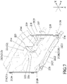
- FIG. 7 is a fragmentary perspective view of a frame body unit of the embodiment.
- FIG. 8 is a perspective view of a transport unit, a transport unit drive motor and a feed vise unit of the embodiment
- FIG. 9 is a perspective view of a hold-down unit and a hold-down unit drive motor of the embodiment.
- FIG. 10 is a fragmentary perspective view of the frame body unit and a cutting unit of the embodiment.
- FIG. 11 is a perspective view of the embodiment from another perspective to that of FIG. 9 .
- the embodiment of the band saw machine according to the present disclosure is suitable for cutting a lumber 100 and adapted to be connected with an exhaust fan (not shown).
- the band saw machine includes a frame body unit 2 , a transport unit 3 , a hold-down unit 4 , a cutting unit 5 , a drive unit 6 , and a feed vise unit 7 .
- the frame body unit 2 includes a support frame module 21 and a cutting shroud module 22 .
- the support frame module 21 has an upright base plate 211 formed with an outlet port 214 that extends therethrough in a front-rear direction (X), a surrounding wall 212 projecting forward from a periphery of the base plate 211 , and a cover plate 213 connected to a front end of the surrounding wall 212 and formed with an inlet port 215 that extends therethrough in the front-rear direction (X) and that is in alignment with the outlet port 214 .
- the support frame module 21 further has two sawdust discharge ports 216 extending through the surrounding wall 212 respectively on the left and right sides, an air vent 217 extending through the surrounding wall 212 and adapted to be connected to the exhaust fan, and a vent housing 218 connected to the base plate 211 and cooperating with the base plate 211 to define an air guide duct 2181 therebetween.
- the air guide duct 2181 has two opposite ends communicating respectively with the air vent 217 and the cutting shroud module 22 .
- the support frame module 21 further has an upper aperture 219 formed through a top of the vent housing 218 and communicating with the air guide duct 2181 , and a lower aperture 210 formed through a bottom of the vent housing 218 and communicating with the air guide duct 281 .
- the surrounding wall 212 has a top wall portion 2121 , a bottom wall portion 2122 disposed under the top wall portion 2121 , and first and second side wall portions 2123 , 2124 connected between the top wall portion 2121 and the bottom wall portion 2122 .
- the air vent 217 extending through the first side wall portion 2123 of the surrounding wall 212 .
- the bottom wall portion 2122 has a generally inverted V-shaped profile section 2125 formed by a central crest 2126 , two inclined segments 2127 that extend respectively, obliquely and downwardly from opposite ends of the central crest 2126 , and two extension segments 2128 that extend respectively from lower ends of the two inclined segments 2127 .
- the extension segments 2128 extend respectively, obliquely and upwardly from the inclined segments 2127 .
- the sawdust discharge ports 216 extend respectively through the extension segments 2128 and located respectively adjacent to the inclined segments 2127 .
- the cover plate 213 has two door panels 2131 defining the inlet port 215 and operable between an open position and a closed position.
- the cutting shroud module 22 is connected to the front of the base plate 211 , and has a shroud body 221 disposed circumferentially around the outlet port 214 , extending forward and parallel to the front-rear direction (X) from the base plate 211 , and defining a feed channel 222 that communicates with the inlet port 215 and the outlet port 214 .
- the shroud body 221 has a first port 223 and a second port 224 that are formed respectively on opposite sides of the shroud body 221 in a left-right direction (Y) which is perpendicular to the front-rear direction (X), and that communicate with the feed channel 222 .
- the first side wall portion 2123 and the second side wall portion 2124 of the surrounding wall 212 face respectively the first port 223 and the second port 224 .
- the opposite ends of the air guide duct 218 communicate respectively with the first port 223 and air vent 217 for exhausting sawdust through the air vent 217 with the suction of the exhaust fan.
- the transport unit 3 includes g a conveyor table 31 connected to the frame body unit 2 and extending in the front-rear direction (X) through the inlet port 215 and the outlet port 214 and extending through the feed channel 222 , a transport pulley set 32 including two transport pulley members 321 that are mounted on the conveyor table 31 and that are spaced apart, from each other in the front-rear direction (X), and an endless conveyor belt 33 trained on the transport pulley members 32 and driven rotatably by the two transport pulley members 321 to convey the lumber 100 from upstream of the inlet port 215 to downstream of the outlet port 214 .
- upstream/upstream side or front refers to the direction where the lumber is fed from
- downstream/downstream side or rear refers to the opposite direction where the lumber is going to get cut.
- the hold-downed unit 4 includes a track frame 41 connected to the frame body unit 2 and extending in the front-rear direction (X) through the inlet port 215 and the outlet port 214 and extending through the feed channel 222 , a hold-down belt roller set 42 including three hold-down belt roller members 421 that are pivotally mounted to the track frame 41 and that are spaced apart from each other in the front-rear direction (X), and an endless hold-down belt 43 trained on the hold-down belt roller members 421 and driven rotatably by the three hold-down belt roller members 421 .
- the hold-down belt 43 is in the form of a roller chain, but is not limited thereto.
- the cutting unit 5 is connected to the support frame module 21 and includes a first cutter module 51 and a second cutter module 52 disposed under the first cutter module 51 and spaced apart from the first cutter module 51 in the up-down direction (Z).
- the first cutter module 51 includes a first wheel set 511 that includes two first wheel members 513 connected to the base plate 211 and spaced apart from each other in the left-right direction (Y) and a first continuous band saw blade 512 trained on the first wheel members 513 and driven rotatably by the two first drive wheel members 513 .
- the first continuous band saw blade 512 has a cutting section travelling alongside the outlet port 214 , extending through the first port 223 and the second port 224 of the cutting shroud module 22 , disposed between the transport unit 3 and the hold-down unit 4 , and adapted to cut the lumber 100 .
- the second cutter module 52 includes a second wheel set 521 that includes two second wheel members 523 connected to the base plate 211 and spaced apart from each other in the left-right direction (Y), and a second continuous band saw blade 522 trained on the second drive wheels 523 and driven rotatably by the two second wheel members 523 .
- the second continuous band saw blade 522 has a cutting section travelling alongside the outlet port 214 , extending through the first port 223 and the second port 224 of the cutting shroud module 22 , disposed between the first cutter module 51 and the transport unit 3 , and that is adapted to cut the lumber 100 .
- One of the first wheel member 513 and the first continuous band saw blade 512 extend into the air guide duct 2181 (see FIG. 7 ) through the upper aperture 219 .
- One of the second wheel members 523 and the second continuous band saw blade 522 extend into the air guide duct 2181 through the lower aperture 210 .
- the drive unit 6 is disposed on the frame body unit 2 , and includes a transport unit drive motor 61 and a hold-down unit drive motor 62 that are connected respectively to the transport pulley set 32 and the hold-down belt roller set 42 and that are operable for respectively and synchronously driving rotations of said transport pulley members 321 and said hold-down belt roller members 421 to rotate the endless conveyor belt 33 and the endless hold-down belt 43 .
- the drive unit 6 further includes a first main drive motor 63 that is connected to the first wheel set 511 and that is operable for driving rotation of the first wheel members 513 to rotate the first continuous band saw blade 512 , and a second main drive motor 64 that is connected to the second wheel set 521 and that is operable for driving rotation of the second wheel members 523 to rotate the second continuous band saw blade 322 .
- the feed vise unit 7 includes an upstanding fixed jaw plate 711 disposed on the conveying table 31 of the transport unit 3 to the right of the conveying belt 33 at upstream to the first continuous band saw blade 512 , a positioning plate 712 disposed to the left of the conveyor belt 33 and movable parallel to the left-right direction (Y) a movable jaw plate 713 disposed between the fixed jaw plate 711 and the positioning plate 712 , and two cushioning members 714 connected between the movable jaw plate 713 and the positioning plate 712 .
- the movable jaw plate 713 is driven to move parallel to the left-right direction (Y) relative to the fixed jaw 711 .
- the cushioning members 714 are springs, but are not limited thereto.
- the exhaust fan is connected to the air vent 217 .
- the lumber 100 is laid on the conveyor belt 33 of the transport unit 3 at upstream to the inlet port 215 , and the movable jaw plate 713 and the fixed jaw plate 711 are manipulated to abut respectively against left and the right lateral sides of the lumber 100 to restrict the cutting width of the lumber 100 in the left-right direction (Y).
- the lumber 100 is carried downstream by the conveyor belt 33 .
- hold-down belt 43 clamps down the lumber 100 to maintain it firmly against the conveyor belt 33 in the up-down direction (Z).
- the lumber 100 With the rotation of the conveyor belt 33 and the hold-down belt 43 , the lumber 100 is carried through the inlet port 215 to get cut by the first and second continuous band saw blades 512 , 522 , the lumber 100 will be cut into three thinner pieces when moving past the first and second continuous band saw blades 512 , 522 .
- the hold down belt 43 loops from upstream of the inlet port 215 to downstream of the outlet port 214 , and the first continuous band saw blade 512 and the second continuous band saw blade 522 transversely extend between the inlet port 215 and the outlet port 214 , during the cutting operation, the hold-down belt 43 will continue to maintain the lumber 100 firmly against the conveyor belt 33 from upstream of the inlet port 215 where the lumber 100 has yet been cut to downstream of the outlet port 214 where the lumber 100 has been cut, so as to restrict the lumber 100 in the up-down direction (Z) to enhance stability.
- a portion of the sawdust (not shown) produced during the cutting operation of the lumber 100 falls to the bottom wall portion 2122 of the surrounding wall 212 of the support frame module 21 and slides down along the inclined segments 2127 and the extension segment 2128 .
- An additional exhaust fan may be connected at the discharge ports 216 to draw the sawdust to be discharged via the discharge ports 216 .
- the remaining sawdust will be entrained by the airflow created by the exhaust fan connected at the air vent 217 to be discharged from the air vent 217 through the first port 223 and the air guide duct 2181 , so that it will not accumulate on the conveyor belt 33 and affects the sawing effect.
- the three pieces of the lumber 100 are continued to be carried downstream by the endless conveyor belt 33 and the endless hold-down belt 43 to exit the outlet port 214 to and thus completing the cutting operation.
- the door panels 2131 of the cover plate 213 are normally closed during cutting operation to prevent scattering of sawdust attached to the first and the second continuous band saw blades 512 , 522 , whereas at down time, the door panels 2131 can be opened for cleaning the sawdust attached to surfaces of the support frame module 21 , the cutting shroud module 22 and other components, and enabling accessibility for maintenance as well.
- the first wheel set 511 and the first continuous band saw blade 512 are disposed in front of the base plate 211
- the second wheel set 521 and the second continuous band saw blade 522 are also disposed in front of the base plate 211 .
- the first wheel set 511 , the first continuous band saw blade 512 , the second wheel set 521 , and the second continuous band saw blade 522 may either be disposed behind the base plate 211 .
- the surrounding wall 212 is connected to the rear of and projects rearward from the base plate 211
- the cover plate 213 is connected to the rearward free end of the surrounding wall 212 .
- the first continuous band saw blade 512 and the second continuous band saw blade 522 are adapted to cut the lumber 100 in an interspace between the transport unit 3 and the hold-down unit 4 with the respective cutting sections travelling alongside the outlet port 214 .
- the hold-down belt roller set 42 can be driven by the hold-down unit drive motor 62 and in turn drive the endless hold-down belt 43 , rather than being frictionally driven by the lumber 100 as in the prior art. Therefore, the endless hold-down belt 43 and the endless conveyor belt 33 are arranged to cooperatively move the lumber 100 , thereby obviating the movement speed loss of the lumber caused by friction resistance between the lumber and the unpowered hold-down unit as in the prior art.
- the sawdust falling on the bottom wall 2122 of the surrounding wall 212 of the support frame module 21 will slide down along the slope of the inclined segment 2127 and the extension segment 2128 to be discharged from the sawdust discharge port 216 , the remaining sawdust will be discharged from the air vent 217 through the first port 223 and the air guide duct 2181 .
Landscapes
- Life Sciences & Earth Sciences (AREA)
- Engineering & Computer Science (AREA)
- Mechanical Engineering (AREA)
- Wood Science & Technology (AREA)
- Forests & Forestry (AREA)
- Sawing (AREA)
- Debarking, Splitting, And Disintegration Of Timber (AREA)
Abstract
Description
Claims (8)
Applications Claiming Priority (2)
| Application Number | Priority Date | Filing Date | Title |
|---|---|---|---|
| TW108116418A TWI691393B (en) | 2019-05-13 | 2019-05-13 | Sawing machine |
| TW108116418 | 2019-05-13 |
Publications (2)
| Publication Number | Publication Date |
|---|---|
| US20200361112A1 US20200361112A1 (en) | 2020-11-19 |
| US11338465B2 true US11338465B2 (en) | 2022-05-24 |
Family
ID=71134649
Family Applications (1)
| Application Number | Title | Priority Date | Filing Date |
|---|---|---|---|
| US16/726,330 Active 2040-09-06 US11338465B2 (en) | 2019-05-13 | 2019-12-24 | Band saw machine |
Country Status (2)
| Country | Link |
|---|---|
| US (1) | US11338465B2 (en) |
| TW (1) | TWI691393B (en) |
Citations (14)
| Publication number | Priority date | Publication date | Assignee | Title |
|---|---|---|---|---|
| US2669261A (en) * | 1952-06-25 | 1954-02-16 | Wells Mfg Corp | Hydraulically-adjustable horizontal band-sawing machine |
| US4285257A (en) * | 1980-02-07 | 1981-08-25 | General Battery Corporation | Apparatus for separating battery plates |
| US5286230A (en) * | 1989-08-11 | 1994-02-15 | Heinz Nienstadt Maschinenfabrik Gmbh | Apparatus for dividing deep-frozen foodstuffs, with recovery of foodstuffs detached during said division |
| US20040007110A1 (en) * | 2000-10-30 | 2004-01-15 | Long John W. | Horizontal meat slicer with bandsaw blade |
| US6772665B1 (en) * | 2002-05-03 | 2004-08-10 | Ennis J. Hurdle, Jr. | Band saw with reciprocating workpiece and method of using |
| US20100031798A1 (en) * | 2008-08-06 | 2010-02-11 | Vivian Wang | Horizontal Band-Saw |
| US20110197729A1 (en) * | 2007-03-20 | 2011-08-18 | Pallet Recyclers LLC | Pallet dismantler |
| CN203371604U (en) | 2013-07-12 | 2014-01-01 | 诸义锋 | Double-side positioning and fixing bisection multi-piece material handling machine |
| US20160008995A1 (en) * | 2014-04-15 | 2016-01-14 | Uwe Reifenhaeuser | Device and method for cutting a frozen food strand into slices |
| CN205343321U (en) | 2016-01-06 | 2016-06-29 | 吴海胜 | Novel band saw machine of full automatization multi -disc |
| US9687006B1 (en) * | 2009-01-30 | 2017-06-27 | Hormel Foods Corporation | Loin back-rib auto-saw |
| CN207373333U (en) | 2017-05-12 | 2018-05-18 | 南京金时川绿色节能材料有限公司 | A kind of band sawing machine dust guard |
| CN207724510U (en) | 2017-12-08 | 2018-08-14 | 佛山市顺德区骏泓成机械制造有限公司 | A kind of Horizontal band sawdust collection structure |
| US20190061027A1 (en) * | 2017-08-31 | 2019-02-28 | Keuro Besitz Gmbh & Co. Edv-Dienstleistungs Kg | Band saw machine |
-
2019
- 2019-05-13 TW TW108116418A patent/TWI691393B/en active
- 2019-12-24 US US16/726,330 patent/US11338465B2/en active Active
Patent Citations (14)
| Publication number | Priority date | Publication date | Assignee | Title |
|---|---|---|---|---|
| US2669261A (en) * | 1952-06-25 | 1954-02-16 | Wells Mfg Corp | Hydraulically-adjustable horizontal band-sawing machine |
| US4285257A (en) * | 1980-02-07 | 1981-08-25 | General Battery Corporation | Apparatus for separating battery plates |
| US5286230A (en) * | 1989-08-11 | 1994-02-15 | Heinz Nienstadt Maschinenfabrik Gmbh | Apparatus for dividing deep-frozen foodstuffs, with recovery of foodstuffs detached during said division |
| US20040007110A1 (en) * | 2000-10-30 | 2004-01-15 | Long John W. | Horizontal meat slicer with bandsaw blade |
| US6772665B1 (en) * | 2002-05-03 | 2004-08-10 | Ennis J. Hurdle, Jr. | Band saw with reciprocating workpiece and method of using |
| US20110197729A1 (en) * | 2007-03-20 | 2011-08-18 | Pallet Recyclers LLC | Pallet dismantler |
| US20100031798A1 (en) * | 2008-08-06 | 2010-02-11 | Vivian Wang | Horizontal Band-Saw |
| US9687006B1 (en) * | 2009-01-30 | 2017-06-27 | Hormel Foods Corporation | Loin back-rib auto-saw |
| CN203371604U (en) | 2013-07-12 | 2014-01-01 | 诸义锋 | Double-side positioning and fixing bisection multi-piece material handling machine |
| US20160008995A1 (en) * | 2014-04-15 | 2016-01-14 | Uwe Reifenhaeuser | Device and method for cutting a frozen food strand into slices |
| CN205343321U (en) | 2016-01-06 | 2016-06-29 | 吴海胜 | Novel band saw machine of full automatization multi -disc |
| CN207373333U (en) | 2017-05-12 | 2018-05-18 | 南京金时川绿色节能材料有限公司 | A kind of band sawing machine dust guard |
| US20190061027A1 (en) * | 2017-08-31 | 2019-02-28 | Keuro Besitz Gmbh & Co. Edv-Dienstleistungs Kg | Band saw machine |
| CN207724510U (en) | 2017-12-08 | 2018-08-14 | 佛山市顺德区骏泓成机械制造有限公司 | A kind of Horizontal band sawdust collection structure |
Non-Patent Citations (1)
| Title |
|---|
| Search Report for TW108116418 dated Sep. 9, 2019, 2 pages. |
Also Published As
| Publication number | Publication date |
|---|---|
| TWI691393B (en) | 2020-04-21 |
| US20200361112A1 (en) | 2020-11-19 |
| TW202041340A (en) | 2020-11-16 |
Similar Documents
| Publication | Publication Date | Title |
|---|---|---|
| US5722474A (en) | Method and apparatus for cutting a cant into boards | |
| US20010045150A1 (en) | Feedworks device | |
| CN107921583B (en) | Apparatus for cutting sheet metal from a sheet metal strip | |
| JP6243388B2 (en) | Band saw machine | |
| CN115157384A (en) | A dust-free pull rod miter saw | |
| US6749492B2 (en) | Rotary sanding machine with a dust collecting mechanism | |
| US11338465B2 (en) | Band saw machine | |
| US20080078276A1 (en) | Panel saw machine for panels made of wood or similar materials | |
| US11260554B2 (en) | Band saw machine having a cleaning unit | |
| US7150216B2 (en) | Sawdust-free wood cutting method and apparatus | |
| CN201483609U (en) | pencil slat hexahedral processing machine | |
| CA1201364A (en) | Firewood sawing apparatus | |
| JPH05508354A (en) | Woodworking machines such as sanding machines that perform traversing | |
| CA2513702A1 (en) | A panel turning device | |
| CN115488523A (en) | Lid diaphragm production uses high efficiency cutting device behind cell-phone | |
| NL8004824A (en) | SAWING DEVICE WITH A CHIPPING EXTRACTOR. | |
| CN211305019U (en) | A vertical band sawing machine with chip removal function | |
| EP2789437A1 (en) | An apparatus for cutting and splitting of tree trunk such as log | |
| TW202332564A (en) | Thickness planer | |
| CN109531299B (en) | Bearing outer surface grinding, conveying and processing integrated machine | |
| US1762023A (en) | Sawing machine | |
| TWI896085B (en) | A band saw machine | |
| CN111823326A (en) | Woodwork cutting device | |
| US5707273A (en) | Multiple-pad orbital sander with split pad platen | |
| CN222644852U (en) | Suction device for planer |
Legal Events
| Date | Code | Title | Description |
|---|---|---|---|
| AS | Assignment |
Owner name: BLUE STEEL MACHINERY CO., TAIWAN Free format text: ASSIGNMENT OF ASSIGNORS INTEREST;ASSIGNOR:HUANG, YU-SHENG;REEL/FRAME:051361/0784 Effective date: 20191202 |
|
| FEPP | Fee payment procedure |
Free format text: ENTITY STATUS SET TO UNDISCOUNTED (ORIGINAL EVENT CODE: BIG.); ENTITY STATUS OF PATENT OWNER: SMALL ENTITY |
|
| FEPP | Fee payment procedure |
Free format text: ENTITY STATUS SET TO SMALL (ORIGINAL EVENT CODE: SMAL); ENTITY STATUS OF PATENT OWNER: SMALL ENTITY |
|
| STPP | Information on status: patent application and granting procedure in general |
Free format text: APPLICATION DISPATCHED FROM PREEXAM, NOT YET DOCKETED |
|
| STPP | Information on status: patent application and granting procedure in general |
Free format text: DOCKETED NEW CASE - READY FOR EXAMINATION |
|
| STPP | Information on status: patent application and granting procedure in general |
Free format text: NON FINAL ACTION MAILED |
|
| STPP | Information on status: patent application and granting procedure in general |
Free format text: NOTICE OF ALLOWANCE MAILED -- APPLICATION RECEIVED IN OFFICE OF PUBLICATIONS |
|
| STPP | Information on status: patent application and granting procedure in general |
Free format text: PUBLICATIONS -- ISSUE FEE PAYMENT VERIFIED |
|
| STCF | Information on status: patent grant |
Free format text: PATENTED CASE |
|
| MAFP | Maintenance fee payment |
Free format text: PAYMENT OF MAINTENANCE FEE, 4TH YR, SMALL ENTITY (ORIGINAL EVENT CODE: M2551); ENTITY STATUS OF PATENT OWNER: SMALL ENTITY Year of fee payment: 4 |