US11337599B2 - Washing tool and endoscope system - Google Patents
Washing tool and endoscope system Download PDFInfo
- Publication number
- US11337599B2 US11337599B2 US16/253,389 US201916253389A US11337599B2 US 11337599 B2 US11337599 B2 US 11337599B2 US 201916253389 A US201916253389 A US 201916253389A US 11337599 B2 US11337599 B2 US 11337599B2
- Authority
- US
- United States
- Prior art keywords
- main body
- distal
- framing section
- tool main
- section
- Prior art date
- Legal status (The legal status is an assumption and is not a legal conclusion. Google has not performed a legal analysis and makes no representation as to the accuracy of the status listed.)
- Active, expires
Links
Images


Classifications
-
- A—HUMAN NECESSITIES
- A61—MEDICAL OR VETERINARY SCIENCE; HYGIENE
- A61B—DIAGNOSIS; SURGERY; IDENTIFICATION
- A61B1/00—Instruments for performing medical examinations of the interior of cavities or tubes of the body by visual or photographical inspection, e.g. endoscopes; Illuminating arrangements therefor
- A61B1/12—Instruments for performing medical examinations of the interior of cavities or tubes of the body by visual or photographical inspection, e.g. endoscopes; Illuminating arrangements therefor with cooling or rinsing arrangements
- A61B1/121—Instruments for performing medical examinations of the interior of cavities or tubes of the body by visual or photographical inspection, e.g. endoscopes; Illuminating arrangements therefor with cooling or rinsing arrangements provided with means for cleaning post-use
- A61B1/123—Instruments for performing medical examinations of the interior of cavities or tubes of the body by visual or photographical inspection, e.g. endoscopes; Illuminating arrangements therefor with cooling or rinsing arrangements provided with means for cleaning post-use using washing machines
-
- A—HUMAN NECESSITIES
- A61—MEDICAL OR VETERINARY SCIENCE; HYGIENE
- A61B—DIAGNOSIS; SURGERY; IDENTIFICATION
- A61B1/00—Instruments for performing medical examinations of the interior of cavities or tubes of the body by visual or photographical inspection, e.g. endoscopes; Illuminating arrangements therefor
- A61B1/12—Instruments for performing medical examinations of the interior of cavities or tubes of the body by visual or photographical inspection, e.g. endoscopes; Illuminating arrangements therefor with cooling or rinsing arrangements
- A61B1/121—Instruments for performing medical examinations of the interior of cavities or tubes of the body by visual or photographical inspection, e.g. endoscopes; Illuminating arrangements therefor with cooling or rinsing arrangements provided with means for cleaning post-use
- A61B1/125—Instruments for performing medical examinations of the interior of cavities or tubes of the body by visual or photographical inspection, e.g. endoscopes; Illuminating arrangements therefor with cooling or rinsing arrangements provided with means for cleaning post-use using fluid circuits
-
- A—HUMAN NECESSITIES
- A61—MEDICAL OR VETERINARY SCIENCE; HYGIENE
- A61B—DIAGNOSIS; SURGERY; IDENTIFICATION
- A61B1/00—Instruments for performing medical examinations of the interior of cavities or tubes of the body by visual or photographical inspection, e.g. endoscopes; Illuminating arrangements therefor
- A61B1/00064—Constructional details of the endoscope body
- A61B1/00071—Insertion part of the endoscope body
- A61B1/0008—Insertion part of the endoscope body characterised by distal tip features
- A61B1/00098—Deflecting means for inserted tools
-
- A—HUMAN NECESSITIES
- A61—MEDICAL OR VETERINARY SCIENCE; HYGIENE
- A61B—DIAGNOSIS; SURGERY; IDENTIFICATION
- A61B1/00—Instruments for performing medical examinations of the interior of cavities or tubes of the body by visual or photographical inspection, e.g. endoscopes; Illuminating arrangements therefor
- A61B1/00064—Constructional details of the endoscope body
- A61B1/00071—Insertion part of the endoscope body
- A61B1/0008—Insertion part of the endoscope body characterised by distal tip features
- A61B1/00101—Insertion part of the endoscope body characterised by distal tip features the distal tip features being detachable
-
- A—HUMAN NECESSITIES
- A61—MEDICAL OR VETERINARY SCIENCE; HYGIENE
- A61B—DIAGNOSIS; SURGERY; IDENTIFICATION
- A61B1/00—Instruments for performing medical examinations of the interior of cavities or tubes of the body by visual or photographical inspection, e.g. endoscopes; Illuminating arrangements therefor
- A61B1/12—Instruments for performing medical examinations of the interior of cavities or tubes of the body by visual or photographical inspection, e.g. endoscopes; Illuminating arrangements therefor with cooling or rinsing arrangements
- A61B1/121—Instruments for performing medical examinations of the interior of cavities or tubes of the body by visual or photographical inspection, e.g. endoscopes; Illuminating arrangements therefor with cooling or rinsing arrangements provided with means for cleaning post-use
- A61B1/122—Instruments for performing medical examinations of the interior of cavities or tubes of the body by visual or photographical inspection, e.g. endoscopes; Illuminating arrangements therefor with cooling or rinsing arrangements provided with means for cleaning post-use using cleaning tools, e.g. brushes
-
- A—HUMAN NECESSITIES
- A61—MEDICAL OR VETERINARY SCIENCE; HYGIENE
- A61B—DIAGNOSIS; SURGERY; IDENTIFICATION
- A61B90/00—Instruments, implements or accessories specially adapted for surgery or diagnosis and not covered by any of the groups A61B1/00 - A61B50/00, e.g. for luxation treatment or for protecting wound edges
- A61B90/70—Cleaning devices specially adapted for surgical instruments
-
- B—PERFORMING OPERATIONS; TRANSPORTING
- B08—CLEANING
- B08B—CLEANING IN GENERAL; PREVENTION OF FOULING IN GENERAL
- B08B3/00—Cleaning by methods involving the use or presence of liquid or steam
- B08B3/04—Cleaning involving contact with liquid
- B08B3/10—Cleaning involving contact with liquid with additional treatment of the liquid or of the object being cleaned, e.g. by heat, by electricity or by vibration
-
- G—PHYSICS
- G02—OPTICS
- G02B—OPTICAL ELEMENTS, SYSTEMS OR APPARATUS
- G02B23/00—Telescopes, e.g. binoculars; Periscopes; Instruments for viewing the inside of hollow bodies; Viewfinders; Optical aiming or sighting devices
- G02B23/24—Instruments or systems for viewing the inside of hollow bodies, e.g. fibrescopes
- G02B23/2476—Non-optical details, e.g. housings, mountings, supports
-
- G—PHYSICS
- G02—OPTICS
- G02B—OPTICAL ELEMENTS, SYSTEMS OR APPARATUS
- G02B27/00—Optical systems or apparatus not provided for by any of the groups G02B1/00 - G02B26/00, G02B30/00
- G02B27/0006—Optical systems or apparatus not provided for by any of the groups G02B1/00 - G02B26/00, G02B30/00 with means to keep optical surfaces clean, e.g. by preventing or removing dirt, stains, contamination, condensation
-
- A—HUMAN NECESSITIES
- A61—MEDICAL OR VETERINARY SCIENCE; HYGIENE
- A61B—DIAGNOSIS; SURGERY; IDENTIFICATION
- A61B90/00—Instruments, implements or accessories specially adapted for surgery or diagnosis and not covered by any of the groups A61B1/00 - A61B50/00, e.g. for luxation treatment or for protecting wound edges
- A61B90/70—Cleaning devices specially adapted for surgical instruments
- A61B2090/701—Cleaning devices specially adapted for surgical instruments for flexible tubular instruments, e.g. endoscopes
Definitions
- the present invention relates to a washing tool for washing a distal framing section of an insertion section of an endoscope, and relates to an endoscope system including the washing tool and the endoscope.
- Jpn. Pat. Appln. KOKAI Publication No. H8-252211 discloses a structure in which a cover is detachably attached to a distal framing section of an insertion section of an endoscope.
- a cup is filled with a liquid such as a washing liquid and water.
- the cover is detached from the distal framing section, so that the distal framing section is washed while being immersed in the liquid filled in the cup.
- a washing tool includes that: a washing tool main body configured to be attached to a distal framing section of an insertion section of an endoscope in place of a cover which is configured to be attached to the distal framing section, the washing tool main body being configured to accommodate the distal framing section in an inside of the washing tool main body in a state where the washing tool main body is attached to the distal framing section; and a supplier configured to supply a fluid to the inside of the washing tool main body.
- FIG. 1 is a schematic diagram of an endoscope system of a first embodiment
- FIG. 2 is a cross-sectional diagram schematically showing a state in which a cover is attached to a distal framing section of the first embodiment, as viewed in a cross section substantially perpendicular to a first intersecting direction,
- FIG. 3A is a schematic diagram of the distal framing section of the first embodiment viewed from one side in the first intersecting direction
- FIG. 3B is a schematic diagram of the distal framing section of the first embodiment viewed from one side in a second intersecting direction
- FIG. 3C is a schematic diagram of the distal framing section of the first embodiment viewed from the other side in the second intersecting direction,
- FIG. 3D is a schematic diagram of the distal framing section of the first embodiment viewed from a distal side
- FIG. 4A is a schematic diagram of the cover to be attached to the distal framing section of the first embodiment viewed from a side where an opening hole is open to the outside,
- FIG. 4B is a schematic diagram of the cover of the first embodiment viewed from a side where a guide protrusion is located with respect to a central axis
- FIG. 4C is a schematic diagram of the cover of the first embodiment viewed from a side where a lock hole is located with respect to the central axis
- FIG. 5A is a cross-sectional diagram schematically showing a washing tool main body of a washing tool of the first embodiment, as viewed in a cross section substantially parallel with the central axis and passing through connection sleeves,
- FIG. 5B is a schematic diagram of the washing tool main body of the first embodiment viewed from an insertion opening side
- FIG. 6 is a schematic diagram showing a state in which the distal framing section is being washed using the washing tool of the first embodiment
- FIG. 7A is a cross-sectional diagram schematically showing a state in which the washing tool main body is attached to the distal framing section of the first embodiment, as viewed in a cross section substantially perpendicular to the second intersecting direction,
- FIG. 7B is a cross-sectional diagram schematically showing a cross section substantially perpendicular to the central axis at position Z 1 -Z 1 in FIG. 7A ,
- FIG. 8 is a cross-sectional diagram schematically showing a state in which a washing liquid is being supplied to the distal framing section located at a predetermined position in a storage portion of the washing tool main body of the first embodiment, as viewed in a cross section substantially perpendicular to the second intersecting direction,
- FIG. 9A is a cross-sectional diagram schematically showing a state in which the distal framing section with the cover of the first embodiment attached thereto is inserted in the storage portion of the washing tool main body, as viewed in a cross section substantially perpendicular to the second intersecting direction,
- FIG. 9B is a cross-sectional diagram schematically showing a state in which the distal framing section with the cover of the first embodiment attached thereto is inserted in the storage portion of the washing tool main body, as viewed in a cross section substantially perpendicular to the longitudinal axis and passing through the distal framing section and the cover,
- FIG. 10A is a schematic diagram of a distal framing section of a first modification viewed from one side in the second intersecting direction
- FIG. 10B is a cross-sectional diagram schematically showing a state in which a washing tool main body of the first modification is attached to the distal framing section, as viewed in a cross section substantially perpendicular to the longitudinal axis and passing through a position located on an opening window side with respect to a distal end of the distal framing section,
- FIG. 11A is a cross-sectional diagram schematically showing a washing tool main body of a second modification, as viewed in a cross section substantially parallel with the central axis and passing through connection sleeves,
- FIG. 11B is a schematic diagram of the washing tool main body of the second modification viewed from the insertion opening side
- FIG. 12A is a cross-sectional diagram schematically showing a state in which the washing tool main body is attached to a distal framing section of the second modification, as viewed in a cross section substantially perpendicular to the second intersecting direction,
- FIG. 12B is a cross-sectional diagram schematically showing a state in which the washing tool main body is attached to the distal framing section of the second modification, as viewed in a cross section substantially perpendicular to the longitudinal axis and passing through the distal framing section,
- FIG. 13A is a cross-sectional diagram schematically showing a state in which the distal framing section with a cover of the second modification attached thereto is inserted in the storage portion of the washing tool main body, as viewed in a cross section substantially perpendicular to the second intersecting direction,
- FIG. 13B is a cross-sectional diagram schematically showing a state in which the distal framing section with the cover of the second modification attached thereto is inserted in the storage portion of the washing tool main body, as viewed in a cross section substantially perpendicular to the longitudinal axis and passing through the distal framing section and the cover,
- FIG. 14A is a cross-sectional diagram schematically showing a washing tool main body of a third modification, as viewed in a cross section substantially parallel with the central axis and passing through connection sleeves,
- FIG. 14B is a schematic diagram of the washing tool main body of the third modification viewed from the insertion opening side
- FIG. 15A is a cross-sectional diagram schematically showing a state in which the washing tool main body is attached to a distal framing section of the third modification, as viewed in a cross section substantially perpendicular to the second intersecting direction,
- FIG. 15B is a cross-sectional diagram schematically showing a state in which the washing tool main body is attached to the distal framing section of the third modification, as viewed in a cross section substantially perpendicular to the longitudinal axis and passing through the distal framing section,
- FIG. 16A is a cross-sectional diagram schematically showing a state in which the distal framing section with a cover of the third modification attached thereto is inserted in the storage portion of the washing tool main body, as viewed in a cross section substantially perpendicular to the second intersecting direction,
- FIG. 16B is a cross-sectional diagram schematically showing a state in which the distal framing section with the cover of the third modification attached thereto is inserted in the storage portion of the washing tool main body, as viewed in a cross section substantially perpendicular to the longitudinal axis and passing through the distal framing section and the cover,
- FIG. 17A is a cross-sectional diagram schematically showing a state in which the washing tool main body is attached to a distal framing section of a fourth modification, as viewed in a cross section substantially perpendicular to the second intersecting direction,
- FIG. 17B is a cross-sectional diagram schematically showing a cross section substantially perpendicular to the longitudinal axis at position Z 2 -Z 2 in FIG. 17A ,
- FIG. 18A is a schematic diagram of a washing tool main body of a fifth modification viewed from a side where the opening window is located with respect to the central axis,
- FIG. 18B is a cross-sectional diagram schematically showing a state in which the washing tool main body is attached to a distal framing section of the fifth modification, as viewed in a cross section substantially perpendicular to the first intersecting direction,
- FIG. 19A is a cross-sectional diagram schematically showing a washing tool main body of a sixth modification, as viewed in a cross section substantially parallel with the central axis,
- FIG. 19B is a schematic diagram of a state in which turning pieces are closed in the washing tool main body of the sixth modification, as viewed from the insertion opening side,
- FIG. 20 is a schematic diagram of a state in which the turning pieces are opened in the washing tool main body of the sixth modification, as viewed from the insertion opening side,
- FIG. 21 is a schematic diagram of a washing tool of a seventh modification
- FIG. 22A is a schematic diagram of a washing tool of an eighth modification.
- FIG. 22B is a schematic diagram illustrating a method of detaching the cover from the distal framing section by using a jig provided in the washing tool of the eighth modification.
- FIGS. 1 to 9B A first embodiment of the present invention will be described with reference to FIGS. 1 to 9B .
- FIG. 1 shows an endoscope system 1 of the present embodiment.
- the endoscope system 1 includes a washing tool 2 , as shown in FIG. 1 .
- the washing tool 2 includes a washing tool main body 10 and a supply section (supplier) 11 .
- a storage portion (storage cavity) 12 which is a cavity for accommodating a washing target, is formed inside the washing tool main body 10 , so that the washing tool main body 10 has a hollow shape.
- the supply section 11 supplies a fluid such as a washing liquid to the storage portion 12 in the washing tool main body 10 .
- Examples of a material forming the washing tool main body 10 include, but are not limited to, polycarbonate, a modified PPE resin, polysulfone containing glass, polyphenylsulfone, and stainless steel.
- connection sleeves 13 A and 13 B are provided on an outer peripheral portion of the washing tool main body 10 .
- the supply section 11 includes supply tubes 15 A and 15 B, branch pipes 16 A and 16 B, suction tubes 17 A and 17 B, and syringes 18 A and 18 B.
- the branch pipe 16 A includes an outflow end E 1 A, an inflow end E 2 A, and a syringe connection end E 3 A.
- the branch pipe 16 B includes an outflow end E 1 B, an inflow end E 2 B, and a syringe connection end E 3 B.
- One end of the supply tube 15 A is connected to the connection sleeve 13 A, and the other end of the supply tube 15 A is connected to the outflow end E 1 A of the branch pipe 16 A.
- one end of the supply tube 15 B is connected to the connection sleeve 13 B, and the other end of the supply tube 15 B is connected to the outflow end E 1 B of the branch pipe 16 B.
- One end of the suction tube 17 A is connected to the inflow end E 2 A of the branch pipe 16 A, and one end of the suction tube 17 B is connected to the inflow end E 2 B of the branch pipe 16 B.
- a suction port VA is formed at the other end of the suction tube 17 A, and a suction port VB is formed at the other end of the suction tube 17 B.
- the syringe 18 A is attached to the syringe connection end E 3 A of the branch pipe 16 A, and the syringe 18 B is attached to the syringe connection end E 3 B of the branch pipe 16 B.
- the liquid as a fluid flows from the suction port VA into the storage portion 12 of the washing tool main body 10 through the suction tube 17 A, the branch pipe 16 A, and the supply tube 15 A in the mentioned order.
- the syringe 18 B is actuated while the suction port VB is immersed in a liquid such as a washing liquid
- the liquid as a fluid flows from the suction port VB into the storage portion 12 of the washing tool main body 10 through the suction tube 17 B, the branch pipe 16 B, and the supply tube 15 B in the mentioned order.
- the fluid such as a washing liquid is supplied to the storage portion 12 .
- the endoscope system 1 includes an endoscope 3 , which is an insertion device.
- the endoscope 3 includes an elongated insertion section 20 to be inserted into a conduit such as a lumen.
- the insertion section 20 extends along a longitudinal axis C defined as a central axis.
- One side along the longitudinal axis C is defined as a distal side (arrow C 1 side), and a side opposite to the distal side is defined as a proximal side (arrow C 2 side).
- the endoscope 3 includes an operation section 21 provided on the proximal side with respect to the insertion section 20 .
- a proximal end of the insertion section 20 is connected to the operation section 21 , and the operation section 21 can be held by a user.
- One end of a universal cord 22 is connected to the operation section 21 .
- the endoscope 3 is used together with one or more of peripheral devices (not shown in the drawings).
- the other end of the universal cord 22 is connected to one of peripheral devices.
- peripheral devices include an image processing device (image processor), a display device (display), a light source device (light source), an air supply source device (air supply source), a liquid supply source device (liquid supply source), and a suction source device (suction source).
- the insertion section 20 includes a distal framing section (distal frame) 23 , a bending section (bending tube) 25 connected to the proximal side of the distal framing section 23 , and a tubular section (elongated tube) 27 connected to the proximal side of the bending section 25 .
- the distal framing section 23 is provided in a distal portion of the insertion section 20 , and forms a distal end of the insertion section 20 .
- the tubular section 27 has flexibility, so that the endoscope 3 is a so-called flexible endoscope.
- the tubular section 27 is rigid, so that the endoscope 3 is a so-called rigid endoscope.
- the bending section 25 is bent by, for example, operating a knob 28 of the operation section 21 .
- the known bending mechanism is actuated based on the operation of the knob 28 , whereby the bending section 25 is bent.
- a distal end of the tubular section 27 may be connected to the distal framing section 23 without providing the bending section 25 .
- the endoscope system 1 includes a cover 5 .
- the cover 5 is detachably attached to the distal framing section 23 . While using the endoscope 3 , for example, observing a lumen using the endoscope 3 , the cover 5 is attached to the distal framing section 23 . In one example, the cover 5 is replaced each time the endoscope 3 is used. In this case, the cover 5 is detached from the distal framing section 23 by, for example, destroying a part of the cover 5 using a predetermined jig or by hand after using the endoscope 3 . Then, the detached cover 5 is discarded.
- the cover 5 is detached from the distal framing section 23 without destroying the cover 5 , and the detached cover 5 is washed and sterilized. Then, before using the endoscope 3 next time, the cover 5 is reattached to the distal framing section 23 , so that the cover 5 is reused. In either case, the cover 5 attached to the distal framing section 23 is not easily detached from the distal framing section 23 when the endoscope 3 is used.
- the washing tool main body 10 is attached to the distal framing section 23 in a state where the cover 5 is detached from the distal framing section 23 . Namely, the washing tool main body 10 is attached to the distal framing section 23 instead of the cover 5 . With the washing tool main body 10 attached to the distal framing section 23 , the distal framing section 23 is housed in the storage portion 12 inside the washing tool main body 10 .
- FIG. 2 shows a state in which the cover 5 is attached to the distal framing section 23 .
- FIGS. 3A to 3D show the distal framing section 23 in a state where neither the cover 5 nor the washing tool main body 10 is attached to the distal framing section 23 .
- a first intersecting direction (direction indicated by arrows X 1 and X 2 ) intersecting the longitudinal axis C is defined, and a second intersecting direction (direction indicated by arrows Y 1 and Y 2 ) intersecting the longitudinal axis C and intersecting the first intersecting direction is defined.
- FIG. 2 shows a cross section substantially perpendicular to the first intersecting direction, and FIG.
- FIG. 3A shows the distal framing section 23 viewed from one side (arrow X 1 side) in the first intersecting direction.
- FIG. 3B shows the distal framing section 23 viewed from one side (arrow Y 1 side) in the second intersecting direction
- FIG. 3C shows the distal framing section 23 viewed from the other side (arrow Y 2 side) in the second intersecting direction.
- FIG. 3D shows the distal framing section 23 viewed from the distal side (arrow C 1 side).
- the direction intersecting the longitudinal axis C as the first intersecting direction, and the direction intersecting the longitudinal axis C and the first intersecting direction as the second intersecting direction are each considered to be, for example, a substantially perpendicular direction.
- the distal framing section 23 includes a block-shaped distal portion main body (distal frame main body) 30 .
- the distal portion main body 30 is formed of a hard material. Examples of the hard material forming the distal portion main body 30 include, but are not limited to, a stainless steel material.
- the distal portion main body 30 is, for example, connected to the distal side of the bending section 25 .
- the central axis of the distal portion main body 30 is substantially coaxial with the longitudinal axis C.
- the distal portion main body 30 includes a wall portion (wall) 31 , and the wall portion 31 includes a flat surface portion (flat surface) 31 A.
- the flat surface portion 31 A forms a part of an outer peripheral surface of the distal portion main body 30 and faces one side (arrow X 1 side) in the first intersecting direction. Also, the flat surface portion 31 A forms an end face of the wall portion 31 on one side (arrow X 1 side) in the first intersecting direction. The wall portion 31 forms an end of the distal portion main body 30 on one side (arrow Y 1 side) in the second intersecting direction.
- an observation window 32 A and an illumination window 32 B are fixed to the wall portion 31 of the distal portion main body 30 .
- An imaging element (not shown in the drawings) such as a CCD is built in the distal portion main body 30 .
- the imaging element images an object through the observation window 32 A.
- an image signal is transmitted from the imaging element to the aforementioned image processing device via an imaging cable (not shown in the drawings), the imaging cable extending through the inside of the insertion section 20 , the inside of the operation section 21 , and the inside of the universal cord 22 .
- an image of the object is generated by the image processing device, and the generated image is displayed on the aforementioned display device.
- a light guide (not shown in the drawings) extends through the inside of the insertion section 20 , the inside of the operation section 21 , and the inside of the universal cord 22 .
- the light emitted from the aforementioned light source device is guided through the light guide.
- the object is irradiated through the illumination window 32 B.
- the illumination window 32 B is located on the distal side with respect to the observation window 32 A.
- one side (arrow X 1 side) in the first intersecting direction is an observing direction of the imaging element.
- the endoscope 3 is formed as a side-viewing or oblique-viewing endoscope in which the direction intersecting the longitudinal axis C of the insertion section 20 is the observing direction of the imaging element. Also, in the present embodiment, the observation window 32 A and the illumination window 32 B are located on one side (arrow Y 1 side) in the second intersecting direction with respect to the longitudinal axis C.
- a nozzle 33 is fixed to the distal portion main body 30 .
- an ejection port 35 of the nozzle 33 is located on the proximal side and on one side (arrow X 1 side) in the first intersecting direction with respect to the observation window 32 A and the illumination window 32 B. Also, the ejection port 35 is located on a side (arrow Y 1 side) where the observation window 32 A is located with respect to the longitudinal axis C, according to the second intersecting direction.
- a distal end of a supply tube 36 is connected to the nozzle 33 .
- a gas such as air is supplied from the aforementioned air supply source device to the nozzle 33 through the supply tube 36 .
- a liquid such as physiological saline is supplied from the aforementioned liquid supply source device to the nozzle 33 through the supply tube 36 .
- the nozzle 33 ejects the supplied liquid and/or gas to the flat surface portion 31 A, where the observation window 32 A and the illumination window 32 B are disposed, from the ejection port 35 toward the distal side.
- a cavity 37 is formed in the distal framing section 23 by the distal portion main body 30 .
- the cavity 37 is provided adjacent to the wall portion 31 in the second intersecting direction.
- the cavity 37 is located on a side (arrow Y 2 side) opposite to the observation window 32 A in the second intersecting direction with respect to the longitudinal axis C.
- the cavity 37 opens toward the distal side, one side (arrow X 1 side) in the first intersecting direction, and the other side (arrow X 2 side) in the first intersecting direction.
- the distal portion main body 30 includes a wall portion (wall) 38 , and the wall portion 38 includes a flat surface portion (flat surface) 38 A.
- the flat surface portion 38 A forms a part of the outer peripheral surface of the distal portion main body 30 , and faces the observing direction of the imaging element, which is one side (arrow X 1 side) in the first intersecting direction. Also, the flat surface portion 38 A is located on a side (arrow Y 2 side) opposite to the observation window 32 A (flat surface portion 31 A) in the second intersecting direction with respect to the longitudinal axis C. The wall portion 38 is spaced from the wall portion 31 by the cavity 37 in the second intersecting direction. In the present embodiment, the flat surface portion 38 A is located on a side (arrow X 2 side) opposite to the observing direction of the imaging element with respect to the flat surface portion 31 A, according to the first intersecting direction. The position of the flat surface portion 38 A in the first intersecting direction is not limited, and the flat surface portion 38 A may located on the same side as the observing direction of the imaging element (arrow X 1 side) with respect to the flat surface portion 31 A.
- a channel 40 extends from the proximal side to the distal side in the insertion section 20 , as shown in FIG. 1 .
- the channel 40 extends, for example, through the inside of a channel tube (not shown in the drawings) and the inside of the distal portion main body 30 .
- a distal end of the channel 40 communicates with the cavity 37 in the distal framing section 23 .
- a proximal end of the channel 40 opens to the outside of the endoscope 3 in a distal side portion of the operation section 21 .
- a forceps plug 41 is attached to an opening at the proximal end of the channel 40 .
- a treatment tool (not shown in the drawings) is inserted from the opening at the proximal end of the channel 40 into the channel 40 .
- the treatment tool inserted through the channel 40 protrudes from the cavity 37 of the distal framing section 23 to the outside of the insertion section 20 .
- the treatment tool protrudes from the cavity 37 to the outside of the insertion section 20 in the state of being inserted through the insertion section 20 .
- a suction path 42 is branched from the channel 40 inside the operation section 21 .
- the suction path 42 extends to the universal cord 22 through a suction changeover valve (not shown in the drawings) of the operation section 21 , and opens to the outside of the endoscope 3 at the suction changeover valve.
- the aforementioned suction source device sucks aspirate from the cavity 37 of the distal framing section 23 through the channel 40 and the suction path 42 .
- a swing table (raising base) 43 is arranged in the cavity 37 of the distal framing section 23 , as shown in FIG. 2 to FIG. 3D .
- the swing table 43 is arranged between the wall portions 31 and 38 in the cavity 37 , according to the second intersecting direction.
- a support shaft 45 is fixed to the swing table 43 .
- a shaft receiver 46 with which the support shaft 45 is engaged is formed in the distal portion main body 30 .
- the support shaft 45 projects from the swing table 43 to both sides in the second intersecting direction, and the shaft receiver 46 is a groove or a hole into which the portion of the support shaft 45 projecting from the swing table 43 is inserted.
- the support shaft 45 engages with the shaft receiver 46 , whereby the swing table 43 is attached to the distal portion main body 30 .
- the swing table 43 is turnable with respect to the distal portion main body 30 about the central axis of the support shaft 45 . Namely, the swing table 43 turns about the central axis of the support shaft 45 as a predetermined rotation axis. In the present embodiment, the central axis of the support shaft 45 is substantially parallel to the second intersecting direction.
- the shaft receiver 46 opens toward the side (arrow X 2 side) opposite to the observing direction of the imaging element. Therefore, the support shaft 45 is exposed to the outside of the insertion section 20 when the cover 5 is not attached to the distal framing section 23 .
- the swing table 43 and the support shaft 45 can be slightly moved on the shaft receiver 46 relative to the distal portion main body 30 in a direction intersecting the central axis of the support shaft 45 when the cover 5 is not attached to the distal framing section 23 , so that the swing table 43 and the support shaft 45 rattle against the distal portion main body 30 .
- the slight movement distance of the swing table 43 and the support shaft 45 relative to the distal portion main body 30 is preferably equal to or greater than one fourth of the diameter of the support shaft 45 .
- a wire 47 extends inside the insertion section 20 from the proximal side toward the distal side.
- a distal end of the wire 47 is connected to the swing table 43 in the cavity 37 of the distal framing section 23 .
- a proximal end of the wire 47 is connected to a lever 48 (see FIG. 1 ) provided to the operation section 21 .
- the wire 47 moves toward the proximal side or the distal side based on the manipulation of the lever 48 .
- the swing table 43 turns with respect to the distal portion main body 30 , as described above, so that the swing table 43 is raised or lowered in the cavity 37 .
- the swing table 43 includes a first surface 51 facing the observing direction of the imaging element, which is one side (arrow X 1 side) in the first intersecting direction, and a second surface 52 facing a side opposite to the first surface 51 .
- the aforementioned treatment tool (not shown in the drawings) inserted through the channel 40 contacts the first surface 51 of the swing table 43 in the cavity 37 . Also, the treatment tool protrudes from the cavity 37 to the outside of the insertion section 20 in the observing direction of the imaging element.
- the swing table 43 is raised or lowered, the direction of the treatment tool protruding to the outside of the insertion section 20 is changed. As a result, the direction of the treatment tool can be adjusted so that the portion of the treatment tool protruding to the outside of the insertion section 20 is within the visual field of the imaging element.
- a curved surface portion (curved surface) 53 is formed on the outer peripheral surface of the distal portion main body 30 .
- the curved surface portion 53 is formed in an arc shape having a radius RO with the longitudinal axis C substantially in the center, when viewed in the cross section substantially perpendicular to the longitudinal axis C.
- the curved surface portion 53 is continuous between the wall portions 31 and 38 . Therefore, on the outer peripheral surface of the distal portion main body 30 , the curved surface portion 53 extends from a portion facing one side (arrow Y 1 side) in the second intersecting direction to a portion facing the other side (arrow Y 2 side) in the second intersecting direction. Also, on the outer peripheral surface of the distal portion main body 30 , the curved surface portion 53 extends between the wall portions 31 and 38 through a portion facing the side (arrow X 2 side) opposite to the observing direction of the imaging element.
- the curved portion 53 of the distal portion main body 30 is provided with a guide groove 55 .
- the guide groove 55 is recessed inwardly and extends from the proximal side toward the distal side.
- the guide groove 55 is located on the side (arrow Y 1 side) where the observation window 32 A (flat surface portion 31 A) is located in the second intersecting direction with respect to the longitudinal axis C.
- the guide groove 55 extends from a distal face to a proximal portion of the distal portion main body 30 along the longitudinal axis C.
- the guide groove 55 is provided at a position that is approximately 90° away from the flat surface portion 31 A around the longitudinal axis C.
- a lock pin 57 is fixed to the curved surface portion 53 of the distal portion main body 30 .
- the lock pin 57 projects to the outer periphery side.
- the lock pin 57 is located on the side (arrow Y 2 side) opposite to the observation window 32 A and the guide groove 55 with respect to the longitudinal axis C, according to the second intersecting direction.
- the lock pin 57 is provided at a position that is approximately 90° away from the flat surface portion 31 A and is approximately 180° away from the guide groove 55 around the longitudinal axis C.
- FIGS. 4A to 4C respectively show a structure of the cover 5 to be attached to the distal framing section 23 .
- the cover 5 is disassembled into members.
- the cover 5 has a central axis S, as shown in FIGS. 2 and 4A to 4C .
- the cover 5 is attached to the distal framing section 23 with the central axis S substantially coaxial with the longitudinal axis C of the insertion section 20 .
- the cover 5 is formed of two members, which are a cover main body 60 and a ring member 61 fixed to the proximal side of the cover main body 60 .
- the cover main body 60 and the ring member 61 preferably have electrically insulating properties.
- the cover main body 60 is preferably formed of plastic.
- the plastic forming the cover main body 60 include, but are not limited to, polysulfone, polyethylene, and polycarbonate.
- the ring member 61 is preferably formed of rubber. Examples of the rubber forming the ring member 61 include, but are not limited to, silicone rubber and fluororubber.
- the cover 5 need not be formed of two bodies as described above, but may be formed of one body made of plastic or rubber.
- the cover main body 60 includes a distal wall 62 and a peripheral wall 63 , and an opening hole 65 for communicating the inside and the outside of the cover main body 60 is formed in the peripheral wall 63 .
- the opening hole 65 With the opening hole 65 , the inner part of the cover 5 is opened in a direction intersecting the central axis S.
- FIG. 4A shows the cover 5 viewed from a side where the opening hole 65 opens to the outside. With the cover 5 attached to the distal framing section 23 , the opening hole 65 is located on the observing direction side of the imaging element (arrow X 1 side) with respect to the longitudinal axis C.
- the cover 5 attached to the distal framing section 23 the side where the opening hole 65 opens to the outside substantially coincides with the observing direction of the imaging element. Therefore, with the cover attached to the distal framing section 23 , the flat surface portion 31 A including the observation window 32 A and the illumination window 32 B, the cavity 37 , the flat surface portion 38 A, and the swing table 43 are exposed to the outside of the cover 5 through the opening hole 65 . Also, the treatment tool inserted through the channel 40 protrudes from the cavity 37 to the outside of the cover 5 through the opening hole 65 .
- An engagement groove 67 that is recessed inwardly is formed in a proximal portion of the outer peripheral surface of the cover main body 60 .
- a flange portion 68 is provided adjacent to the proximal side of the engagement groove 67 .
- the flange portion 68 protrudes to the outer periphery side with respect to the engagement groove 67 , and forms a proximal end of the cover main body 60 .
- the engagement groove 67 and the flange portion 68 are formed over the entire circumference around the central axis S. Also, the engagement groove 67 and the flange portion 68 are located on the proximal side (arrow C 2 side) with respect to the opening hole 65 .
- An engagement protrusion 71 protruding inwardly is provided on the inner peripheral surface of the ring member 61 .
- a distal end of the ring member 61 is formed by the engagement protrusion 71 .
- On the inner peripheral surface of the ring member 61 a flange engagement groove 72 is provided adjacent to the proximal side of the engagement protrusion 71 .
- the flange engagement groove 72 is recessed toward the outer periphery side on the inner peripheral surface of the ring member 61 .
- the engagement protrusion 71 engages with the engagement groove 67
- the flange engagement groove 72 engages with the flange portion 68 , whereby the ring member 61 is fixed to the cover main body 60 .
- a guide protrusion 74 as a cover engagement portion (cover engagement) is provided on the inner peripheral surface of the cover main body 60 .
- the guide protrusion 74 protrudes inwardly and extends from the proximal side toward the distal side.
- the guide protrusion 74 preferably extends from a proximal portion to a distal portion in the cover main body 60 .
- the guide protrusion 74 is provided at a position that is approximately 90° away from the opening hole 65 around the central axis S.
- FIG. 4B shows the cover 5 viewed from the side where the guide protrusion 74 is located with respect to the central axis S.
- the guide protrusion 74 When attaching the cover 5 to the distal framing section 23 , the guide protrusion 74 is engaged with the guide groove 55 of the distal portion main body 30 , and the guide protrusion 74 is moved toward the proximal side in the guide groove 55 . Thereby, the cover 5 moves toward the proximal side relative to the distal framing section 23 and is attached to the distal framing section 23 . Even in the state where the cover 5 is attached to the distal framing section 23 , the guide protrusion 74 engages with the guide groove 55 .
- the guide protrusion 74 is located on the side (arrow Y 1 side) where the guide groove 55 and the observation window 32 A are located with respect to the longitudinal axis C, in the second intersecting direction. Also, the engagement of the guide protrusion 74 with the guide groove 55 restricts the movement of the cover 5 and the insertion section 20 (distal framing section 23 ) with respect to each other around the longitudinal axis C (central axis S). Therefore, the guide groove 55 and the guide protrusion 74 position the cover 5 with respect to the distal framing section 23 around the longitudinal axis C.
- a lock hole 75 as a cover engagement portion (cover engagement) is formed in the cover main body 60 .
- the lock hole 75 penetrates from the engagement groove 67 to the inside of the cover main body 60 .
- the lock hole 75 is provided at a position that is approximately 90° away from the opening hole 65 and at a position that is approximately 180° away from the guide protrusion 74 around the central axis S.
- FIG. 4C shows the cover 5 viewed from the side where the lock hole 75 is located with respect to the central axis S.
- the guide protrusion 74 is moved toward the proximal side in the guide groove 55 , whereby the cover 5 is moved toward the proximal side relative to the distal framing section 23 up to a position where the portion of the lock pin 57 of the distal framing section 23 projecting toward the outer periphery side can be inserted into the lock hole 75 , that is, a position where the lock pin 57 can be engaged with the lock hole 75 . Then, with the guide protrusion 74 engaged with the guide groove 55 , the lock pin 57 is engaged with the lock hole 75 , whereby the cover 5 is attached to the distal framing section 23 .
- the lock hole 75 is located on the side (arrow Y 2 side) where the lock pin 57 and the cavity 37 are located with respect to the longitudinal axis C, according to the second intersecting direction. Also, the engagement of the lock pin 57 with the lock hole 75 restricts the movement of the cover 5 and the insertion section 20 (distal framing section 23 ) with respect to each other along the longitudinal axis C (central axis S). Therefore, the lock pin 57 and the lock hole 75 position the cover 5 with respect to the distal framing section 23 in a direction along the longitudinal axis C.
- a slit 77 A extends from a proximal edge of the opening hole 65 toward the proximal side
- a slit 77 B extends from the proximal end of the cover main body 60 toward the distal side.
- Each of the slits 77 A and 77 B communicates the outside and the inside of the cover main body 60 .
- the slits 77 A and 77 B are located at approximately the same angle position as each other around the central axis S, and are located at approximately the same angle position as the opening hole 65 around the central axis S.
- the slits 77 A and 77 B are located on the observing direction side of the imaging element (arrow X 1 side) with respect to the longitudinal axis C.
- a distal end of the slit 77 A is continuous with the opening hole 65 .
- a proximal end of the slit 77 A and a distal end of the slit 77 B are not continuous with each other.
- Providing the slits 77 A and 77 B decreases the strength of the part between the proximal end of the slit 77 A and the distal end of the slit 77 B and makes the part between the proximal end of the slit 77 A and the distal end of the slit 77 B fragile, as compared to other adjacent parts. Namely, a fragile portion 78 having a lower strength than other parts of the cover main body 60 is formed between the proximal end of the slit 77 A and the distal end of the slit 77 B in the cover main body 60 .
- the fragile portion 78 is broken using, for example, a predetermined jig or by hand, so that the slits 77 A and 77 B are continuous with each other. Then, the engagement of the lock pin 57 with the lock hole 75 is released using the predetermined jig or by hand.
- the guide protrusion 74 can move in the guide groove 55 along the longitudinal axis C. Then, by moving the guide protrusion 74 toward the distal side in the guide groove 55 , the cover 5 is moved toward the distal side relative to the distal framing section 23 . Thereby, the cover 5 is detached from the distal framing section 23 .
- the ring member 61 covers at least a part of the fragile portion 78 from the outer periphery side. Therefore, at least a part of the fragile portion 78 is not exposed to the outside. Therefore, even if the cover 5 abuts on an inner wall of a lumen, for example, during use of the endoscope 3 such as a state of observing the lumen using the endoscope 3 with the cover 5 attached to the distal framing section 23 , the breakage of the fragile portion 78 is inhibited.
- FIGS. 5A and 5B respectively show a structure of the washing tool main body 10 of the washing tool 2 .
- the washing tool main body 10 has a central axis P, as shown in FIGS. 5A and 5B .
- the washing tool main body 10 includes an inner peripheral surface 80 , and the above-described storage portion (storage cavity) 12 is defined inside the washing tool main body 10 by the inner peripheral surface 80 .
- an insertion opening 81 is formed at an end on one side (arrow P 1 side) in the direction along the central axis P.
- the storage portion 12 is opened to the outside of the washing tool main body 10 through the insertion opening 81 ; however in one example a plurality of opening windows, in addition to the insertion opening 81 , may be provided on the periphery of the storage portion 12 .
- an opening window 82 is formed at an end on the other side (arrow P 2 side) in the direction along the central axis P.
- the storage portion 12 is opened to the outside of the washing tool main body 10 through the opening window 82 .
- FIG. 5A shows a cross section that is substantially parallel to the central axis P and passes through the connection sleeves 13 A and 13 B.
- FIG. 5B shows the washing tool main body 10 viewed from the insertion opening 81 side (arrow P 1 side).
- the washing tool main body 10 includes a wall portion (wall) 83 .
- the wall portion 83 is provided adjacent to the opening window 82 in a direction intersecting (substantially perpendicular to) the central axis P.
- the wall portion 83 includes wall surfaces 83 A and 83 B, and extends toward the insertion opening 81 side from the wall surface 83 A to the wall surface 83 B along the central axis P.
- the wall surface 83 A faces a side (arrow P 2 side) where the opening window 82 opens, and the wall surface 83 B faces a side (arrow P 1 side) where the insertion opening 81 opens.
- the wall surface 83 A of the wall portion 83 forms an end of the washing tool main body 10 on the opening window 82 side (arrow P 2 side) in the direction along the central axis P.
- Inflow ports 85 A and 85 B for allowing a fluid such as a washing liquid to flow into the storage portion 12 are formed in the washing tool main body 10 .
- a fluid supplied through the supply tube 15 A flows into the storage portion 12 from the inflow port 85 A
- a fluid supplied through the supply tube 15 B flows into the storage portion 12 from the inflow port 85 B.
- a restriction pin 87 is fixed to the washing tool main body 10 .
- the restriction pin (protrusion) 87 on the inner peripheral surface 80 of the washing tool main body 10 protrudes inwardly.
- the restriction pin 87 is located on the opening window 82 side with respect to the insertion opening 81 and is located on the insertion opening 81 side with respect to the inflow ports 85 A and 85 B, in a direction along the central axis P.
- the restriction pin 87 is located at a position that is approximately 90° away from the inflow ports 85 A and 85 B around the central axis P.
- Holding portions (holder) 88 A and 88 B protruding inwardly are provided on the inner peripheral surface 80 of the washing tool main body 10 .
- Each of the holding portions 88 A and 88 B extends substantially in parallel with the central axis P.
- Each of the holding portions 88 A and 88 B continuously extends, along the central axis P, in a range from substantially the same position as the restriction pin 87 to the wall surface 83 B of the wall portion 83 .
- the holding portions 88 A and 88 B are located opposite to the inflow ports 85 A and 85 B with respect to the central axis P, in a direction intersecting the central axis P.
- the holding portions 88 A and 88 B are spaced apart from each other around the central axis P.
- the cross-sectional area of the storage portion 12 which is substantially perpendicular to the central axis P and ranges from the insertion opening 81 to the restriction pin 87 (ends of the holding portions 88 A and 88 B on the insertion opening 81 side), is larger than the cross-sectional area of the storage portion 12 , which is substantially perpendicular to the central axis P and ranges from the restriction pin 87 to the wall surface 83 B of the wall portion 83 .
- the cross-sectional area of the storage portion 12 which is substantially perpendicular to the central axis P and ranges from the restriction pin 87 to the wall surface 83 B of the wall portion 83 , is larger than the cross-sectional area of the storage portion 12 , which is substantially perpendicular to the central axis P and ranges from the wall surface 83 B to the opening window 82 .
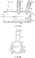
- FIG. 6 shows a state in which the distal framing section 23 is being washed using the washing tool 2 .
- the cover 5 When washing the distal framing section 23 , the cover 5 is detached from the distal framing section 23 , as described above, and instead of the cover 5 , the washing tool main body 10 of the washing tool 2 is attached to the distal framing section 23 , as shown in FIG. 6 . Then, the distal framing section 23 and the washing tool main body 10 attached to the distal framing section 23 are inserted into a tray 91 filled with a washing liquid. As a result, the distal framing section 23 and the washing tool main body 10 are immersed in the washing liquid in the tray 91 .
- the suction port VA of the suction tube 17 A and the suction port VB of the suction tube 17 B are immersed in a washing liquid in a tray 92 .
- the syringe 18 A is actuated, whereby the washing liquid as a fluid is supplied from the suction port VA to the inflow port 85 A through the suction tube 17 A, the branch pipe 16 A, and the supply tube 15 A in the mentioned order, and flows into the storage portion 12 of the washing tool main body 10 from the inflow port 85 A.
- the syringe 18 B is actuated, whereby the washing liquid as a fluid is supplied from the suction port VB to the inflow port 85 B through the suction tube 17 B, the branch pipe 16 B, and the supply tube 15 B in the mentioned order, and flows into the storage portion 12 from the inflow port 85 B. Then, the distal framing section 23 is washed by the washing liquid having flown into the storage portion 12 from the inflow ports 85 A and 85 B.
- FIGS. 7A and 7B respectively show a state in which the washing tool main body 10 is attached to the distal framing section 23 .
- FIG. 7A shows a cross section that is substantially perpendicular to the second intersecting direction
- FIG. 7B shows a cross section that is substantially perpendicular to the central axis P at position Z 1 -Z 1 in FIG. 7A .
- the restriction pin (tool engagement portion) 87 of the washing tool main body 10 is engaged with the guide groove (endoscope engagement portion) 55 of the distal portion main body 30 .
- the engagement of the restriction pin 87 with the guide groove 55 restricts the movement of the washing tool main body 10 and the insertion section 20 (distal framing section 23 ) with respect to each other around the longitudinal axis C (central axis P). Therefore, the restriction pin 87 as a tool engagement portion (tool engagement) positions the washing tool main body 10 with respect to the distal framing section 23 around the longitudinal axis C, so that the restriction pin 87 is at approximately the same angle position as the guide groove 55 as an endoscope engagement portion (endoscope engagement).
- the inflow ports 85 A and 85 B are located on the observing direction side of the imaging element (arrow X 1 side) with respect to the longitudinal axis C, in the first intersecting direction. Therefore, the first surface 51 of the swing table 43 faces the side (arrow X 1 side) where the inflow ports 85 A and 85 B are located with respect to the longitudinal axis C according to the first intersecting direction, and the second surface 52 faces the side (arrow X 2 side) opposite to the side where the inflow ports 85 A and 85 B are located with respect to the longitudinal axis C according to the first intersecting direction.
- the restriction pin 87 With the restriction pin 87 engaged with the guide groove 55 , the restriction pin 87 is moved from the distal side to the proximal side in the guide groove 55 . As a result, the distal framing section 23 moves relative to the washing tool main body 10 from the insertion opening 81 side toward the opening window 82 side in the storage portion 12 . The movement of the distal framing section 23 toward the opening window 82 side (distal side) is restricted by the restriction pin 87 abutting on a proximal edge of the guide groove 55 . Namely, the restriction pin 87 positions the washing tool main body 10 with respect to the distal framing section 23 in the direction along the longitudinal axis C (central axis P).
- the distal framing section 23 moves in the storage portion 12 along the longitudinal axis C until the restriction pin 87 abuts on the proximal edge of the guide groove 55 , whereby the distal framing section 23 is located at a predetermined position in the storage portion 12 where a fluid such as a washing liquid is supplied.
- the restriction pin 87 functions as a position adjuster, and defines the position of the distal framing section 23 inside the washing tool main body 10 , so that the distal framing section 23 is located at the predetermined position where a fluid is supplied.
- the restriction pin 87 as a position adjuster positions the washing tool main body 10 with respect to the distal framing section 23 in the direction along the longitudinal axis C and a direction around the longitudinal axis C.
- the guide groove 55 engages with the guide protrusion (cover engagement portion) 74 of the cover 5 when the cover 5 is attached to the distal framing section 23 . Therefore, with the structure necessary for attaching the cover 5 to the distal framing section 23 , the position of the distal framing section 23 is defined inside the washing tool main body 10 , so that the distal framing section 23 is located at the predetermined position. Namely, the washing tool main body 10 is positioned with respect to the distal framing section 23 without complicating the structure of the distal framing section 23 .
- the holding portions 88 A and 88 B abut on the curved surface portion 53 of the distal portion main body 30 from the outer periphery side.
- a gap is formed between the inner peripheral surface 80 of the washing tool main body 10 and the outer peripheral portion of the distal framing section 23 in an area other than the restriction pin 87 and the holding portions 88 A and 88 B.
- the support shaft 45 and the shaft receiver 46 are located at substantially the same position as the inflow port 85 A in the direction along the longitudinal axis C (central axis P), and are located at substantially the same position as the inflow port 85 A in the second intersecting direction.
- the distal end of the distal framing section 23 is located on the insertion opening 81 side (proximal side) with respect to the inflow port 85 B and the wall portion 83 , and a gap is formed between the distal end of the distal framing section 23 and the wall surface 83 B of the wall portion 83 .
- the distal end of the distal framing section 23 is formed by the swing table 43 , and the distal face of the distal portion main body 30 is located closer to the proximal side than the distal end of the distal framing section 23 .
- FIG. 8 shows a state in which the washing liquid is being supplied to the distal framing section 23 located at the predetermined position in the storage portion 12 of the washing tool main body 10 .
- FIG. 8 shows a cross section that is substantially perpendicular to the second intersecting direction.
- the washing liquid is supplied to the first surface 51 of the swing table 43 and the vicinity thereof. Also, with the distal framing section 23 located at the predetermined position in the storage portion 12 of the washing tool main body 10 , the positional relationship of the distal end of the distal framing section 23 with the inflow port 85 B and the wall portion 83 is as described above. Therefore, the washing liquid (fluid) having flown into the storage portion 12 from the inflow port 85 B passes through the gap between the distal end of the distal framing section 23 and the wall surface 83 B of the wall portion 83 , and flows into a gap between the second surface 52 of the swing table 43 and the inner peripheral surface 80 of the washing tool main body 10 (arrow UB in FIG. 8 ).
- the washing liquid is supplied to the second surface 52 of the swing table 43 and the vicinity thereof.
- the washing liquid is supplied to both the first surface 51 and the second surface 52 of the swing table 43 , as described above. Therefore, the swing table 43 is properly washed.
- the washing tool main body 10 is provided with the insertion opening 81 and the opening window 82 that opens on a side opposite to the insertion opening 81 . Therefore, a drained liquid easily flows out from the storage portion 12 inside the washing tool main body 10 to the outside of the washing tool main body 10 through the insertion opening 81 or the opening window 82 , and hardly accumulates in the storage portion 12 .
- the swing table 43 and the support shaft 45 can be slightly moved on the shaft receiver 46 relative to the distal portion main body 30 in a direction intersecting the central axis of the support shaft 45 . Therefore, ejecting a fluid from the inflow port 85 A to the support shaft 45 and the vicinity thereof makes the support shaft 45 slightly move relative to the shaft receiver 46 by the fluid pressure.
- a distance W 2 between the second surface 52 of the swing table 43 and the inner peripheral surface 80 of the washing tool main body 10 is smaller than a distance W 1 between the distal end of the distal framing section 23 and the wall surface 83 B of the wall portion 83 . Therefore, a flow rate of the fluid passing between the second surface 52 of the swing table 43 and the inner peripheral surface 80 of the washing tool main body 10 is larger than a flow rate of the fluid passing between the distal end of the distal framing section 23 and the wall surface 83 B of the wall portion 83 .
- the support shaft 45 slightly moves relative to the shaft receiver 46 by the fluid pressure. Therefore, in the present embodiment, the support shaft 45 and the swing table 43 are slightly moved relative to the shaft receiver 46 by the washing liquid having flown in from the inflow ports 85 A and 85 B, so that the support shaft 45 is spaced from the shaft receiver 46 . As the support shaft 45 is spaced from the shaft receiver 46 , a gap is formed between the distal portion main body (distal frame main body) 30 , which forms the shaft receiver 46 , and the support shaft 45 . As a result, the support shaft 45 and the vicinity thereof are properly washed, and the swing table 43 is also properly washed.
- FIGS. 9A and 9B respectively show a state in which the distal framing section 23 with the cover 5 attached thereto is inserted into the storage portion 12 of the washing tool main body 10 .
- FIG. 9A shows a cross section that is substantially perpendicular to the second intersecting direction
- FIG. 9B shows a cross section that is substantially perpendicular to the longitudinal axis C and passes through the distal framing section 23 and the cover 5 . As shown in FIG.
- the restriction pin 87 and the holding portions 88 A and 88 B function as regulators, and the restriction pin 87 and the holding portions 88 A and 88 B interfere with the cover 5 , thereby restricting the movement of the distal framing section 23 with the cover 5 attached thereto to the predetermined position.
- the restriction pin (protrusion) 87 as a position adjuster also functions as a regulator.
- restricting the movement to the predetermined position includes restraining the movement to the predetermined position, and means limiting the movement to the predetermined position.
- the distal framing section 23 cannot be moved to the predetermined position in the storage portion 12 when the distal framing section 23 is washed using the washing tool 2 without detaching the cover 5 from the distal framing section 23 after using the endoscope 3 . Therefore, a user can properly recognize that the cover 5 is not detached from the distal framing section 23 . Accordingly, in the present embodiment, only with the cover 5 detached from the distal framing section 23 , the distal framing section 23 can be located at the predetermined position in the storage portion 12 where the washing liquid (fluid) is properly supplied. This reliably prevents the distal framing section 23 from being washed with the cover 5 attached to the distal framing section 23 .
- the user can recognize that the distal framing section 23 is disposed at the predetermined position in the storage portion 12 to be washed.
- Completely washing the distal framing section 23 with the cover 5 detached from the distal framing section 23 allows the detailed parts of the distal framing section 23 , for example, around the swing table (raising base) 43 to be easily and completely washed.
- a guide surface 93 is provided as an endoscope engagement portion (endoscope engagement) instead of the guide groove 55 .
- the guide surface 93 extends from the proximal side toward the distal side, and is located on the side (arrow Y 1 side) where the observation window 32 A (flat portion 31 A) is located with respect to the longitudinal axis C, in the second intersecting direction.
- the guide surface 93 has a flat shape and faces one side (arrow Y 1 side) in the second intersecting direction.
- the guide surface 93 is provided at a position that is approximately 90° away from the flat surface portion 31 A around the longitudinal axis C.
- FIG. 10A shows the distal framing section 23 viewed from one side in the second intersecting direction.
- FIG. 10B shows a state in which the washing tool main body 10 is attached to the distal framing section 23 , as viewed in a cross section that is substantially perpendicular to the longitudinal axis C (central axis P) and passes through a position located on the opening window 82 side with respect to the distal end of the distal framing section 23 .
- the restriction pin (tool engagement portion) 87 of the washing tool main body 10 is engaged with the guide surface (endoscope engagement portion) 93 of the distal portion main body 30 .
- a protruding end of the restriction pin 87 is brought into contact with the guide surface 93 from the outer periphery side.
- the restriction pin 87 as a tool engagement portion (tool engagement) positions the washing tool main body 10 with respect to the distal framing section 23 around the longitudinal axis C, so that the restriction pin 87 is located at approximately the same angle position as the guide surface 93 as an endoscope engagement portion.
- the restriction pin 87 With the restriction pin 87 engaged with the guide surface 93 , namely, with the restriction pin 87 abutting on the guide surface 93 , the restriction pin 87 is moved from the distal side to the proximal side on the guide surface 93 . As a result, the distal framing section 23 moves relative to the washing tool main body 10 from the insertion opening 81 side toward the opening window 82 side in the storage portion 12 . The movement of the distal framing section 23 toward the opening window 82 side (distal side) is restricted by the restriction pin 87 abutting on the step surface 95 at the proximal end of the guide surface 93 .
- the restriction pin 87 positions the washing tool main body 10 with respect to the distal framing section 23 in the direction along the longitudinal axis C (central axis P).
- the distal framing section 23 moves in the storage portion 12 along the longitudinal axis C until the restriction pin 87 abuts on the step surface 95 , whereby the distal framing section 23 is located at the predetermined position in the storage portion 12 where a fluid such as a washing liquid is supplied.
- the restriction pin 87 functions as a position adjuster, and defines the position of the distal framing section 23 inside the washing tool main body 10 , so that the distal framing section 23 is located at the predetermined position where a fluid is supplied.
- the restriction pin 87 and the holding portions 88 A and 88 B function as regulators, and the restriction pin 87 and the holding portions 88 A and 88 B interfere with the cover 5 , thereby restricting the movement of the distal framing section 23 with the cover 5 attached thereto to the predetermined position.
- a restriction protruding portion (restriction protrusion) 100 is provided instead of the restriction pin 87 as a tool engagement portion (tool engagement).
- the restriction protruding portion 100 on the inner peripheral surface 80 of the washing tool main body 10 protrudes inwardly.
- the restriction protruding portion 100 is located at approximately the same angle position as the inflow ports 85 A and 85 B around the central axis P.
- the inflow port 85 A is formed at a protruding end of the restriction protruding portion 100 .
- the restriction protruding portion 100 is located on the insertion opening 81 side with respect to the inflow port 85 B and the wall portion 83 in the direction along the central axis P.
- the restriction protruding portion 100 includes a protruding side face 101 A facing the insertion opening 81 side and a protruding side face 101 B facing the opening window 82 side.
- the restriction protruding portion 100 also includes protruding end faces 102 A and 102 B facing the inner periphery side.
- the protruding end faces 102 A and 102 B are provided adjacent to each other in the direction intersecting the central axis P.
- a step surface 103 is formed between the protruding end faces 102 A and 102 B. Because of the step surface 103 , the protruding end face 102 A is located on the inner periphery side with respect to the protruding end face 102 B.
- FIG. 11A shows the washing tool main body 10 as viewed in a cross section substantially parallel to the central axis P and passing through the connection sleeves 13 A and 13 B.
- FIG. 11B shows the washing tool main body 10 viewed from the insertion opening 81 side.
- FIGS. 12A and 12B respectively show a state in which the washing tool main body 10 is attached to the distal framing section 23 .
- FIG. 12A shows a cross section substantially perpendicular to the second intersecting direction.
- FIG. 12B shows a cross section substantially perpendicular to the longitudinal axis C and passing through the distal framing section 23 .
- FIG. 13A and 13B respectively show a state in which the distal framing section 23 with the cover 5 attached thereto is inserted into the storage portion 12 of the washing tool main body 10 .
- FIG. 13A shows a cross section substantially perpendicular to the second intersecting direction.
- FIG. 13B shows a cross section substantially perpendicular to the longitudinal axis C and passing through the distal framing section 23 and the cover 5 .
- the distal framing section 23 when attaching the washing tool main body 10 to the distal framing section 23 , the distal framing section 23 is inserted into the storage portion 12 of the washing tool main body 10 from the insertion opening 81 in a state where the swing table 43 is lowered. At this time, the distal framing section 23 is moved toward the opening window 82 side in a state where the restriction protruding portion 100 is located on the observing direction side of the imaging element (arrow X 1 side) with respect to the longitudinal axis C, in the first intersecting direction.
- the flat surface portion 38 A of the wall portion 38 and the first surface 51 of the swing table 43 face the protruding end face 102 A, and a part of the flat surface portion 31 A of the wall portion 31 faces the protruding end face 102 B.
- the wall portion 31 is located on the side (arrow Y 1 side) where the protruding end face 102 B is located with respect to the step surface 103 of the restriction protruding portion 100 , as viewed in the second intersecting direction.
- the wall portion 38 and the swing table 43 are located on the side (arrow Y 2 side) where the protruding end face 102 A is located with respect to the step surface 103 of the restriction protruding portion 100 , according to the second intersecting direction.
- the wall portion 31 abuts on the protruding end face 102 B or the step surface 103 , or the swing table 43 or the wall portion 38 abut on the protruding end face 102 A, thereby restricting the movement of the distal framing section 23 relative to the washing tool main body 10 around the longitudinal axis C (central axis P).
- the restriction protruding portion 100 positions the washing tool main body 10 with respect to the distal framing section 23 around the longitudinal axis C, so that the restriction protruding portion 100 is located on the observing direction side of the imaging element (arrow X 1 side) with respect to the longitudinal axis C.
- the first surface 51 of the swing table 43 faces the side (arrow X 1 side) where the inflow ports 85 A and 85 B are located with respect to the longitudinal axis C in the first intersecting direction
- the second surface 52 faces the side (arrow X 2 side) opposite to the side where the inflow ports 85 A and 85 B are located with respect to the longitudinal axis C in the first intersecting direction.
- the distal framing section 23 moves relative to the washing tool main body 10 from the insertion opening 81 side toward the opening window 82 side in the storage portion 12 .
- a distal face 105 of the bending section 25 abuts on the ends of the holding portions 88 A and 88 B on the insertion opening 81 side (proximal side), thereby restricting the movement of the distal framing section 23 toward the opening window 82 side (distal side).
- the holding portions 88 A and 88 B position the washing tool main body 10 with respect to the distal framing section 23 in the direction along the longitudinal axis C (central axis P).
- the movement of the distal framing section 23 relative to the washing tool main body 10 around the longitudinal axis C is restricted by the restriction protruding portion 100 , and the distal framing section 23 moves in the storage portion 12 along the longitudinal axis C until the distal face 105 of the bending section 25 abuts on one end of the holding portions 88 A and 88 B, whereby the distal framing section 23 is located at the predetermined position in the storage portion 12 where a fluid such as a washing liquid is supplied.
- the restriction protruding portion 100 and the holding portions 88 A and 88 B function as position adjusters, and define the position of the distal framing section 23 inside the washing tool main body 10 , so that the distal framing section 23 is located at the predetermined position where a fluid is supplied.
- the distal framing section 23 when the distal framing section 23 is inserted into the storage portion 12 from the insertion opening 81 with the cover 5 attached to the distal framing section 23 , the distal portion of the cover 5 abuts on the protruding side face 101 A of the restriction protruding portion 100 or the holding portions 88 A and 88 B, and interferes with the restriction protruding portion 100 or the holding portions 88 A and 88 B. As a result, the movement of the distal framing section 23 and the cover 5 from the protruding side face 101 A of the restriction protruding portion 100 toward the opening window 82 side (distal side) is restricted.
- the restriction protruding portion 100 and the holding portions 88 A and 88 B function as regulators, and the restriction protruding portion 100 and the holding portions 88 A and 88 B interfere with the cover 5 , thereby restricting the movement of the distal framing section 23 with the cover 5 attached thereto to the predetermined position.
- the restriction protruding portion 100 and the holding portions 88 A and 88 B as position adjusters also function as regulators.
- a distal portion of the swing table 43 interferes with the restriction protruding portion 100 in a state where the swing table 43 is raised, that is, in a state where the swing table 43 is not lowered.
- the movement of the distal framing section 23 with the raised swing table 43 from the protruding side face 101 A of the restriction protruding portion 100 toward the opening window 82 side (distal side) is restricted. Since the distal framing section 23 cannot move from the protruding side face 101 A toward the opening window 82 side in the storage portion 12 , the distal framing section 23 cannot move to the aforementioned predetermined position in the storage portion 12 when the swing table 43 is not lowered. Therefore, in the present modification, the washing tool main body 10 is attached to the distal framing section 23 only with the swing table 43 lowered.
- a restriction inner peripheral surface 106 is provided instead of the restriction pin 87 as a tool engagement portion.
- the restriction inner peripheral surface 106 forms a part of the inner peripheral surface 80 of the washing tool main body 10 and is formed over the entire circumference around the central axis P.
- the restriction inner peripheral surface 106 extends from the opening window 82 toward the insertion opening 81 side.
- the restriction inner peripheral surface 106 protrudes inwardly, as compared to the portion of the inner peripheral surface 80 that is located on the insertion opening 81 side with respect to the restriction inner peripheral surface 106 .
- a step surface 112 is formed at an end of the restriction inner peripheral surface 106 on the insertion opening 81 side in the direction along the central axis P.
- the step surface 112 is formed over the entire circumference around the central axis P.
- the inflow ports 85 A and 85 B are provided on the restriction inner peripheral surface 106 . Therefore, the step surface 112 (end of the restriction inner peripheral surface 106 on the insertion opening 81 side) is located on the insertion opening 81 side (arrow P 1 side) with respect to the inflow port 85 A in the direction along the central axis P.
- the cross-sectional shape of the restriction inner peripheral surface 106 that is substantially perpendicular to the central axis P is substantially D-shaped from the end of the restriction inner peripheral surface 106 on the insertion opening 81 side to the opening window 82 .
- the restriction inner peripheral surface 106 includes a curved surface portion (curved surface) 107 and a flat surface portion (flat surface) 108 , and both ends of the curved surface portion 107 are continuous with the flat surface portion 108 in the cross section substantially perpendicular to the central axis P.
- the inflow ports 85 A and 85 B are formed on the flat surface portion 108 .
- the curved surface portion 107 is formed in an arc shape having a radius RO with the longitudinal axis P substantially in the center, when viewed in the cross section substantially perpendicular to the longitudinal axis P, and the radius RO is approximately equal to the distance from the longitudinal axis C to the curved surface portion 53 of the distal portion main body 30 .
- a protruding portion (protrusion) 111 protruding inwardly from the curved surface portion 107 is provided on the restriction inner peripheral surface 106 .
- the protruding portion 111 extends from the opening window 82 toward the insertion opening 81 side.
- the end of the protruding portion 111 on the insertion opening 81 side is located on the opening window 82 side (arrow P 2 side) with respect to the step surface 112 and the inflow port 85 A in the direction along the central axis P.
- the end of the protruding portion 111 on the insertion opening 81 side is located on the insertion opening 81 side (arrow P 1 side) with respect to the inflow port 85 B in the direction along the central axis P.
- the protruding portion 111 is located at a position that is approximately 180° away from the flat surface portion 108 and the inflow ports 85 A and 85 B around the central axis P.
- FIG. 14A shows the washing tool main body 10 as viewed in a cross section substantially parallel to the central axis P and passing through the connection sleeves 13 A and 13 B.
- FIG. 14B shows the washing tool main body 10 viewed from the insertion opening 81 side.
- FIGS. 15A and 15B respectively show a state in which the washing tool main body 10 is attached to the distal framing section 23 .
- FIG. 15A shows a cross section substantially perpendicular to the second intersecting direction.
- FIG. 15B shows a cross section substantially perpendicular to the longitudinal axis C and passing through the distal framing section 23 .
- FIGS. 16A and 16B respectively show a state in which the distal framing section 23 with the cover 5 attached thereto is inserted into the storage portion 12 of the washing tool main body 10 .
- FIG. 16A shows a cross section substantially perpendicular to the second intersecting direction.
- FIG. 16B shows a cross section substantially perpendicular to the longitudinal axis C and passing through the distal framing section 23 and the cover 5 .
- the distal framing section 23 when attaching the washing tool main body 10 to the distal framing section 23 , the distal framing section 23 is inserted into the storage portion 12 of the washing tool main body 10 from the insertion opening 81 . At this time, the distal framing section 23 is moved toward the opening window 82 side with the flat surface portion 108 located on the observing direction of the imaging element (arrow X 1 side) with respect to the longitudinal axis C, in the first intersecting direction.
- the curved surface portion 107 abuts on the curved surface portion 53 of the distal portion main body 30 from the outer periphery side, and the flat surface portion 108 abuts on the flat surface portion 31 A of the wall portion 31 from the outer periphery side.
- the restriction inner peripheral surface 106 positions the washing tool main body 10 with respect to the distal framing section 23 around the longitudinal axis C, so that the flat surface portion 108 is located on the observing direction side of the imaging element (arrow X 1 side) with respect to the longitudinal axis C.
- the first surface 51 of the swing table 43 faces the side (arrow X 1 side) where the inflow ports 85 A and 85 B are located with respect to the longitudinal axis C according to the first intersecting direction
- the second surface 52 faces the side (arrow X 2 side) opposite to the side where the inflow ports 85 A and 85 B are located with respect to the longitudinal axis C according to the first intersecting direction.
- the distal framing section 23 moves relative to the washing tool main body 10 from the insertion opening 81 side toward the opening window 82 side in the storage portion 12 .
- a distal face 113 of the distal portion main body 30 abuts on the end of the protruding portion 111 on the insertion opening 81 side (proximal side), thereby restricting the movement of the distal framing section 23 toward the opening window 82 side (distal side).
- the protruding portion 111 positions the washing tool main body 10 with respect to the distal framing section 23 in the direction along the longitudinal axis C (central axis P).
- the distal end of the distal framing section 23 is formed by a distal end of the swing table 43
- the distal face 113 of the distal portion main body 30 is located on the proximal side with respect to the distal end of the swing table 43 .
- the movement of the distal framing section 23 relative to the washing tool main body 10 around the longitudinal axis C is restricted by the restriction inner peripheral surface 106 , and the distal framing section 23 moves in the storage portion 12 along the longitudinal axis C until the distal face 113 of the distal portion main body 30 abuts on one end of the protruding portion 111 , whereby the distal framing section 23 is located at the predetermined position in the storage portion 12 where a fluid such as a washing liquid is supplied.
- the restriction inner peripheral surface 106 and the protruding portion 111 function as position adjusters, and define the position of the distal framing section 23 inside the washing tool main body 10 , so that the distal framing section 23 is located at the predetermined position where a fluid is supplied.
- the swing table 43 does not come into contact with the flat surface portion 108 , and the distal framing section 23 can move toward the insertion opening 81 side relative to the washing tool main body 10 . Therefore, the washing tool main body 10 can be detached from the distal framing section 23 .
- the distal framing section 23 when the distal framing section 23 is inserted into the storage portion 12 from the insertion opening 81 with the cover 5 attached to the distal framing section 23 , the distal portion of the cover 5 abuts on the end of the restriction inner peripheral surface 106 on the insertion opening 81 side, that is, the step surface 112 , and interferes with the step surface 112 . As a result, the movement of the distal framing section 23 and the cover 5 from the step surface 112 toward the opening window 82 side (distal side) is restricted.
- the step surface 112 functions as a regulator, and the step surface 112 interferes with the cover 5 , thereby restricting the movement of the distal framing section 23 with the cover 5 attached thereto to the predetermined position.
- the washing tool main body 10 is provided with cuts 115 A and 115 B, in addition to the structure similar to that of the third modification.
- Each of the cuts 115 A and 115 B penetrates from the outside of the washing tool main body 10 to the storage portion 12 .
- the cuts 115 A and 115 B are provided at substantially the same position in the direction along the central axis P, and are arranged approximately 180° away from each other around the central axis P (longitudinal axis C).
- FIG. 17A shows a state in which the washing tool main body 10 is attached to the distal framing section 23 , as viewed in a cross section substantially perpendicular to the second intersecting direction.
- FIG. 17B shows a cross section substantially perpendicular to the longitudinal axis C at position Z 2 -Z 2 in FIG. 17A .
- the thread winding portion 73 provided in the distal portion of the outer peripheral surface of the bending section 25 is located between the O-ring 116 and the step surface 112 in the direction along the central axis P. Therefore, when moving the distal framing section 23 from the insertion opening 81 to the predetermined position, the thread winding portion 73 moves toward the opening window 82 side in the range where the O-ring 116 is provided.
- the distance from the longitudinal axis C to the outer peripheral surface in the thread winding portion 73 that is, the outer diameter of the thread winding portion 73 is larger than that of the distal framing section 23 .
- the O-ring 116 elastically deforms as the thread winding portion 73 moves toward the opening window 82 side in the range where the O-ring 116 is provided. Due to the elastic deformation of the O-ring 116 , the operator can obtain a click feeling. Based on the presence or absence of the click feeling, the operator can determine whether or not the distal framing section 23 has moved to the aforementioned predetermined position in the storage portion 12 .
- the O-ring 116 suppresses the movement of the thread winding portion 73 in the storage portion 12 toward the insertion opening 81 side relative to the O-ring 116 .
- the distal framing section 23 is prevented from moving from the predetermined position toward the insertion opening 81 side due to liquid pressure or the like when being washed by the washing liquid having flown in from the inflow ports 85 A and 85 B. Therefore, the distal framing section 23 is prevented from moving unintentionally toward the insertion opening 81 side.
- the washing tool main body 10 is provided with an opening window 117 penetrating from the outer peripheral surface to the storage portion 12 .
- the opening window 117 is located on the insertion opening 81 side with respect to the inflow ports 85 A and 85 B. Also, the opening window 117 is located at a position that is approximately 90° away from the inflow ports 85 A and 85 B around the central axis P.
- a protruding portion (protrusion) 118 protruding inwardly is provided on the inner peripheral surface 80 of the washing tool main body 10 .
- the protruding portion 118 is formed over the entire circumference around the central axis P.
- the protruding portion 118 also extends from the opening window 82 toward the insertion opening 81 side. Since the protruding portion 118 protrudes inwardly, a step surface 125 is formed at an end of the protruding portion 118 on the insertion opening 81 side in the direction along the central axis P. The step surface 125 is formed over the entire circumference around the central axis P.
- the inflow ports 85 A and 85 B are provided on the protruding portion 118 . Therefore, the step surface 125 (end of the protruding portion 118 on the insertion opening 81 side) is located on the insertion opening 81 side (arrow P 1 side) with respect to the inflow port 85 A in the direction along the central axis P.
- the opening window 117 also extends from the step surface 125 toward the insertion opening 81 side.
- an extension piece 121 extends from the step surface 125 toward the insertion opening 81 side in the storage portion 12 .
- the extension piece 121 protrudes from the step surface 125 toward the insertion opening 81 side.
- the extension piece 121 is located at approximately the same angle position as the opening window 117 around the central axis P. However, the extension piece 121 is located away from the opening window 117 toward the inner periphery side.
- the extension piece 121 is provided with a lock hole 122 as a tool engagement portion (tool engagement) that penetrates through the extension piece 121 .
- the extension piece 121 also includes an end face 123 that forms an end (protruding end) of the extension piece 121 on the insertion opening 81 side.
- the lock hole 122 is located between the end face 123 and the step surface 125 in the direction along the central axis P.
- the lock hole 122 and the end face 123 are located between the edge of the opening window 117 on the insertion opening 81 side and the step surface 125 (edge of the opening window 117 on the opening window 82 side) in the direction along the central axis P.
- FIG. 18A shows the washing tool main body 10 viewed from the side where the opening window 117 is located with respect to the central axis P.
- FIG. 18B shows a state in which the washing tool main body 10 is attached to the distal framing section 23 , as viewed in a cross section substantially perpendicular to the first intersecting direction.
- the distal framing section 23 when attaching the washing tool main body 10 to the distal framing section 23 , the distal framing section 23 is inserted into the storage portion 12 of the washing tool main body 10 from the insertion opening 81 . At this time, the distal framing section 23 is moved toward the opening window 82 side in a state where the lock pin 57 as an endoscope engagement portion (endoscope engagement) is at approximately the same angle position around the longitudinal axis C as the lock hole 122 as a tool engagement portion (tool engagement).
- the distal framing section 23 is moved toward the opening window 82 side with the opening window 117 and the lock hole 122 located on the side (arrow Y 2 side) where the lock pin 57 is located with respect to the longitudinal axis C, in the second intersecting direction. Then, the lock hole (tool engagement portion) 122 of the washing tool main body 10 is engaged with the lock pin (endoscope engagement portion) 57 of the distal framing section 23 .
- the engagement of the lock hole 122 with the lock pin 57 restricts the movement of the washing tool main body 10 and the insertion section 20 (distal framing section 23 ) with respect to each other around the longitudinal axis C (central axis P).
- the lock hole 122 as a tool engagement portion positions the washing tool main body 10 with respect to the distal framing section 23 around the longitudinal axis C, so that the lock hole 122 is at approximately the same angle position as the lock pin 57 as an endoscope engagement portion.
- the first surface 51 of the swing table 43 faces the side (arrow X 1 side) where the inflow ports 85 A and 85 B are located with respect to the longitudinal axis C in the first intersecting direction
- the second surface 52 faces the side (arrow X 2 side) opposite to the side where the inflow ports 85 A and 85 B are located with respect to the longitudinal axis C in the first intersecting direction.
- the lock hole 122 engages with the lock pin 57 , thereby restricting the movement of the distal framing section 23 toward the opening window 82 side (distal side). Namely, the lock hole 122 positions the washing tool main body 10 with respect to the distal framing section 23 in the direction along the longitudinal axis C (central axis P). Therefore, in the present modification, the lock hole 122 engages with the lock pin 57 , whereby the distal framing section 23 is located at the predetermined position in the storage portion 12 where a fluid such as a washing liquid is supplied.
- the lock hole 122 functions as a position adjuster, and defines the position of the distal framing section 23 inside the washing tool main body 10 , so that the distal framing section 23 is located at the predetermined position where a fluid is supplied.
- the lock hole 122 as a position adjuster engages with the lock pin 57 , thereby positioning the washing tool main body 10 with respect to the distal framing section 23 in the direction around the longitudinal axis C and the direction along the longitudinal axis C. Then, the lock pin 57 engages with the lock hole (cover engagement portion) 75 of the cover 5 when attaching the cover 5 to the distal framing section 23 . Therefore, with the structure necessary for attaching the cover 5 to the distal framing section 23 , the position of the distal framing section 23 inside the washing tool main body 10 is defined, so that the distal framing section 23 is located at the predetermined position.
- the lock hole 122 engages with the lock pin 57 , thereby generating a clicking sound. Therefore, the operator can determine, based on the presence or absence of the click feeling, whether or not the distal framing section 23 has moved to the aforementioned predetermined position in the storage portion 12 .
- the operator can release the engagement of the lock hole 122 with the lock pin 57 through the opening window 117 in the state where the distal framing section 23 is located at the aforementioned predetermined position in the storage portion 12 .
- the engagement of the lock hole 122 with the lock pin 57 is easily released. Accordingly, the washing tool main body 10 is easily detached from the distal framing section 23 .
- the distal framing section 23 when the distal framing section 23 is inserted into the storage portion 12 from the insertion opening 81 with the cover 5 attached to the distal framing section 23 , the distal portion of the cover 5 abuts on the end face 123 of the extension piece 121 and interferes with the extension piece 121 . As a result, the movement of the distal framing section 23 and the cover 5 from the end face 123 toward the opening window 82 side (distal side) is restricted.
- the extension piece 121 functions as a regulator, and the extension piece 121 interferes with the cover 5 , thereby restricting the movement of the distal framing section 23 with the cover 5 attached thereto to the predetermined position.
- a groove 126 recessed toward the outer periphery side is formed on the inner peripheral surface 80 of the washing tool main body 10 , in addition to the structure similar to that of the third modification.
- the groove 126 extends continuously from the insertion opening 81 to the opening window 82 along the rotation axis P. Also, the groove 126 is located at a position that is approximately 90° away from the inflow ports 85 A and 85 B around the central axis P.
- the washing tool main body 10 includes turning pieces 127 A and 127 B. The turning pieces 127 A and 127 B are turnable with respect to each other about the rotation axis substantially parallel to the central axis P and passing through the groove 126 .
- the washing tool main body 10 has a hinge structure in which the turning pieces 127 A and 127 B can be opened and closed relative to each other.
- the turning piece 127 A is provided with an engagement protrusion 128 A
- the turning piece 127 B is provided with an engagement depressed portion (engagement recess) 128 B.
- the turning pieces 127 A and 127 B are closed and the engagement protrusion 128 A is engaged with the engagement depressed portion 128 B, whereby the washing tool main body 10 has a tubular shape so that the storage portion 12 is formed therein.
- FIG. 19A shows a cross section that is substantially parallel to the central axis P of the washing tool main body 10 .
- FIG. 19B and FIG. 20 show the washing tool main body 10 viewed from the insertion opening 81 side.
- FIG. 19B shows a state in which the turning pieces 127 A and 127 B are closed and the engagement protrusion 128 A is engaged with the engagement depressed portion 128 B.
- FIG. 20 shows a state in which the turning pieces 127 A and 127 B are opened.
- the distal framing section 23 can be inserted into the storage portion 12 from the insertion opening 81 , and opening the turning pieces 127 A and 127 B also allows the distal framing section 23 to be inserted into the storage portion 12 from the direction intersecting the central axis P.
- the restriction inner peripheral surface 106 and the protruding portion 111 function as position adjusters, and define the position of the distal framing section 23 inside the washing tool main body 10 , so that the distal framing section 23 is located at the predetermined position where a fluid is supplied.
- the distal framing section 23 With the distal framing section 23 located at the aforementioned predetermined position, the turning pieces 127 A and 127 B are closed and the engagement protrusion 128 A is engaged with the engagement depressed portion 128 B. Also, with the turning pieces 127 A and 127 B closed and the engagement protrusion 128 A engaged with the engagement depressed portion 128 B, the distal framing section 23 is washed as described above.
- the step surface 112 interferes with the cover 5 , thereby restricting the movement of the distal framing section 23 with the cover 5 attached thereto to the predetermined position.
- the distal framing section 23 with the cover 5 attached thereto is inserted into the storage portion 12 from the direction intersecting the central axis P with the turning pieces 127 A and 127 B opened, the closing motion of the turning pieces 127 A and 127 B is restricted.
- the turning pieces 127 A and 127 B are not closed, so that the engagement protrusion 128 A cannot be engaged with the engagement depressed portion 128 B.
- the washing tool main body 10 does not have a tubular shape, and the movement of the distal framing section 23 with the cover 5 attached thereto to the predetermined position is restricted. Therefore, in the present modification, the turning pieces 127 A and 127 B also function as regulators, and the turning pieces 127 A and 127 B interfere with the cover 5 , thereby restricting the movement of the distal framing section 23 with the cover 5 attached thereto to the predetermined position.
- a structure may be adopted in which the distal framing section 23 can be inserted into the storage portion 12 only from the direction intersecting the central axis P with the turning pieces 127 A and 127 B opened.
- the distal framing section 23 cannot be inserted into the storage portion 12 from the insertion opening 81 in the direction along the central axis P.
- the structure of the sixth modification in which the turning pieces 127 A and 127 B open and close may be combined with the embodiments, other than the third modification, such as the first embodiment.
- the supply section (supplier) 11 of the washing tool 2 includes pumps 135 A and 135 B in place of the syringes 18 A and 18 B.
- the pump 135 A is driven, so that a liquid such as a washing liquid is supplied to the inflow port 85 A through the supply tube 15 A.
- the pump 135 B is driven, so that a liquid such as a washing liquid is supplied to the inflow port 85 B through the supply tube 15 B.
- only one syringe ( 18 A) or only one pump ( 135 A) may be provided to the supply section 11 .
- the two inflow ports 85 A and 85 B are provided to the washing tool main body 10 , as in the above-described embodiment and the like.
- a supply path branches into two parts at the downstream side of the syringe ( 18 A) or the downstream side of the pump ( 135 A).
- One of the branched parts of the supply path communicates with the inflow port 85 A, and the other branched part of the supply path communicates with the inflow port 85 B.
- three or more inflow ports may be provided to the washing tool main body 10 .
- at least one of the plurality of inflow ports e.g., inflow port 85 A
- at least one of the other inflow ports e.g., inflow port 85 B
- the turning pieces 127 A and 127 B are opened and closed as described in the sixth modification, and after the supply path branches into multiple parts, each of the branched parts of the supply path communicates with a corresponding one of the plurality of inflow ports (e.g., inflow ports 85 A and 85 B).
- the plurality of inflow ports ( 85 A and 85 B) are preferably not provided on both sides with the groove 126 therebetween. Namely, all the inflow ports ( 85 A and 85 B) are preferably formed in only one of the turning pieces 127 A and 127 B. As a result, the operation of engaging the engagement protrusion 125 A and the engagement depressed portion 128 B is less likely to be inhibited by the supply path to the inflow ports ( 85 A and 85 B).
- the washing tool main body 10 is formed in a substantially cylindrical shape; however, if the washing tool main body 10 has a tubular shape so that the storage portion 12 is formed therein, the washing tool main body 10 may be formed in a substantially polygonal tubular shape, such as a substantially quadrangular tubular shape or a substantially triangular tubular shape. Also, in one modification, many opening windows ( 82 ) may be formed on the outer surface of the washing tool main body 10 .
- a jig 130 is detachably attached to the supply tube 15 A in the supply section 11 of the washing tool 2 .
- the jig 130 is, for example, the aforementioned jig used when detaching the cover 5 from the distal framing section 23 .
- Examples of a material forming the jig 130 include, but are not limited to, polycarbonate, a modified PPE resin, polysulfone containing glass, polyphenylsulfone, and stainless steel.
- the jig 130 may be attached to the supply tube 15 B, for example. It is sufficient as long as the jig 130 is attached to any part of the washing tool 2 .
- a cavity 131 into which the distal framing section 23 with the cover 5 attached thereto is inserted is formed in the jig 130 .
- an engagement groove 132 which engages with the supply tube 15 A (or 15 B), is formed in the jig 130 .
- the engagement groove 132 engages with the supply tube 15 A, whereby the jig 130 is attached to the supply tube 15 A.
- the distal framing section 23 with the cover 5 attached thereto is inserted into the cavity 131 of the jig 130 from the distal side (arrow T 1 in FIG. 22B ). Then, the jig 130 is turned with respect to the distal framing section 23 and the cover 5 to one side around the longitudinal axis C (central axis of the jig 130 ). As a result, the fragile portion 78 of the cover 5 is broken as described above, so that the slits 77 A and 77 B are continuous with each other. Then, the engagement of the lock pin 57 with the lock hole 75 is released.
- the jig 130 is attached to the washing tool 2 , it is possible to quickly and easily detach the cover 5 from the distal framing section 23 and attach the washing tool main body 10 to the distal framing section 23 from which the cover 5 has been detached. For example, the trouble of looking for the jig 130 used for detaching the cover 5 from the distal framing section 23 is avoided.
- the endoscope 3 is a side-viewing or oblique-viewing endoscope in which the direction intersecting the longitudinal axis C of the insertion section 20 is the observing direction of the imaging element.
- the endoscope 3 is not limited thereto.
- the above-described structure may be applied to a direct-viewing endoscope in which the direction along the longitudinal axis C of the insertion section 20 is the observing direction of the imaging sensor.
- the washing tool main body ( 10 ) of the washing tool ( 2 ) is attached to the distal framing section ( 23 ) of the insertion section ( 20 ) of the endoscope ( 3 ) in place of the cover ( 5 ), and with the washing tool main body ( 10 ) attached to the distal framing section ( 23 ), the distal framing section ( 23 ) is housed inside the washing tool main body ( 10 ). Also, the washing tool ( 2 ) is provided with the supply section ( 11 ) configured to supply a fluid into the washing tool main body ( 10 ).
- the position of the distal framing section ( 23 ) inside the washing tool main body ( 10 ) is defined by the position adjusters ( 87 ; 88 A, 88 B, 100 ; 106 ; 111 ; 122 ), so that the distal framing section 23 is located at the predetermined position where a fluid is supplied.
- the regulators ( 87 , 88 A, 88 B; 88 A, 88 B, 100 ; 112 ; 121 ; 127 A, 127 B) interfere with the cover ( 5 ) and restrict the movement of the distal framing section ( 23 ) with the cover ( 5 ) attached thereto to the predetermined position.
- the structure of the distal framing section 23 and the structure of the cover 5 are not limited to the above-described embodiment and the like as long as they satisfy such a structure. Also, the structure of attaching the cover 5 to the distal framing section 23 is not limited to the above-described embodiment and the like.
Landscapes
- Health & Medical Sciences (AREA)
- Life Sciences & Earth Sciences (AREA)
- Physics & Mathematics (AREA)
- Surgery (AREA)
- Optics & Photonics (AREA)
- Biomedical Technology (AREA)
- Public Health (AREA)
- Nuclear Medicine, Radiotherapy & Molecular Imaging (AREA)
- Pathology (AREA)
- Veterinary Medicine (AREA)
- Heart & Thoracic Surgery (AREA)
- Engineering & Computer Science (AREA)
- General Health & Medical Sciences (AREA)
- Animal Behavior & Ethology (AREA)
- Molecular Biology (AREA)
- Medical Informatics (AREA)
- Biophysics (AREA)
- Radiology & Medical Imaging (AREA)
- General Physics & Mathematics (AREA)
- Astronomy & Astrophysics (AREA)
- Oral & Maxillofacial Surgery (AREA)
- Endoscopes (AREA)
- Instruments For Viewing The Inside Of Hollow Bodies (AREA)
Abstract
Description
Claims (4)
Applications Claiming Priority (4)
| Application Number | Priority Date | Filing Date | Title |
|---|---|---|---|
| JP2016166069 | 2016-08-26 | ||
| JPJP2016-166069 | 2016-08-26 | ||
| JP2016-166069 | 2016-08-26 | ||
| PCT/JP2017/024689 WO2018037727A1 (en) | 2016-08-26 | 2017-07-05 | Cleaning implement and endoscope system |
Related Parent Applications (1)
| Application Number | Title | Priority Date | Filing Date |
|---|---|---|---|
| PCT/JP2017/024689 Continuation WO2018037727A1 (en) | 2016-08-26 | 2017-07-05 | Cleaning implement and endoscope system |
Publications (2)
| Publication Number | Publication Date |
|---|---|
| US20190150722A1 US20190150722A1 (en) | 2019-05-23 |
| US11337599B2 true US11337599B2 (en) | 2022-05-24 |
Family
ID=61245819
Family Applications (1)
| Application Number | Title | Priority Date | Filing Date |
|---|---|---|---|
| US16/253,389 Active 2037-12-30 US11337599B2 (en) | 2016-08-26 | 2019-01-22 | Washing tool and endoscope system |
Country Status (5)
| Country | Link |
|---|---|
| US (1) | US11337599B2 (en) |
| JP (1) | JP6393855B2 (en) |
| CN (1) | CN109640783B (en) |
| DE (1) | DE112017004260T5 (en) |
| WO (1) | WO2018037727A1 (en) |
Cited By (1)
| Publication number | Priority date | Publication date | Assignee | Title |
|---|---|---|---|---|
| US20210235982A1 (en) * | 2018-10-25 | 2021-08-05 | Olympus Corporation | Endoscope attachment and endoscope system |
Families Citing this family (15)
| Publication number | Priority date | Publication date | Assignee | Title |
|---|---|---|---|---|
| CN110325098A (en) | 2016-11-28 | 2019-10-11 | 适内有限责任公司 | With the endoscope for separating disposable axis |
| JP6731560B2 (en) * | 2018-01-31 | 2020-07-29 | オリンパス株式会社 | Endoscope cleaning tool |
| WO2019150632A1 (en) * | 2018-01-31 | 2019-08-08 | オリンパス株式会社 | Washing tool for insertion instrument |
| JP6901636B2 (en) * | 2018-06-28 | 2021-07-14 | オリンパス株式会社 | Endoscope cleaning tool |
| US11805968B2 (en) | 2019-11-05 | 2023-11-07 | Bayou Surgical, Inc. | Intraoperative endoscope cleaning system |
| USD1018844S1 (en) | 2020-01-09 | 2024-03-19 | Adaptivendo Llc | Endoscope handle |
| USD1051380S1 (en) | 2020-11-17 | 2024-11-12 | Adaptivendo Llc | Endoscope handle |
| US11986361B2 (en) * | 2020-11-17 | 2024-05-21 | Virginia Commonwealth University | Stent retriever cleaning devices and methods |
| USD1031035S1 (en) | 2021-04-29 | 2024-06-11 | Adaptivendo Llc | Endoscope handle |
| USD1070082S1 (en) | 2021-04-29 | 2025-04-08 | Adaptivendo Llc | Endoscope handle |
| EP4340773B1 (en) * | 2021-05-18 | 2025-05-21 | Align Technology, Inc. | Intraoral scanner sleeve |
| USD1073069S1 (en) | 2021-05-18 | 2025-04-29 | Align Technology, Inc. | Protective sleeve for an intraoral scanner |
| USD1066659S1 (en) | 2021-09-24 | 2025-03-11 | Adaptivendo Llc | Endoscope handle |
| EP4493040A4 (en) * | 2022-03-15 | 2026-02-25 | Bayou Surgical Inc | Cleaning devices and systems for surgical instruments and methods for doing so |
| WO2025224699A1 (en) * | 2024-04-26 | 2025-10-30 | Saban Ventures Pty Limited | Modulated cleaning fluid flow |
Citations (16)
| Publication number | Priority date | Publication date | Assignee | Title |
|---|---|---|---|---|
| US5090433A (en) * | 1988-01-28 | 1992-02-25 | Kabushiki Kaisha Toshiba | Compact endoscope cleaning apparatus |
| JPH08252211A (en) | 1995-03-15 | 1996-10-01 | Olympus Optical Co Ltd | Endoscope |
| US20040118440A1 (en) * | 2002-09-13 | 2004-06-24 | Olympus Optical Co., Ltd. | Cleaning device for medical instrument |
| US6919057B2 (en) * | 2002-04-04 | 2005-07-19 | Steris Inc. | Automated endoscope reprocessor |
| US20060020165A1 (en) * | 2004-07-26 | 2006-01-26 | Medtronic Xomed, Inc. | Disposable endoscope sheath having adjustable length |
| US20080188715A1 (en) * | 2006-10-11 | 2008-08-07 | Olympus Medical Systems Corp. | Endoscope cleaning sheath, and endoscope apparatus and endoscope comprising the cleaning sheath |
| US20140318582A1 (en) * | 2013-04-26 | 2014-10-30 | Medtronic-Xomed, Inc. | Endoscope lens cleaning device |
| US20150087907A1 (en) * | 2013-09-26 | 2015-03-26 | Gyrus Acmi, Inc. D.B.A Olympus Surgical Technologies America | Oblong endoscope sheath |
| US20150173597A1 (en) * | 2013-07-03 | 2015-06-25 | Olympus Medical Systems Corp. | Endoscope connection instrument and endoscope cleaning/disinfecting apparatus |
| US20150190041A1 (en) * | 2012-09-28 | 2015-07-09 | Terumo Kabushiki Kaisha | Elongated member for medical use and cleaning device |
| WO2015107801A1 (en) | 2014-01-15 | 2015-07-23 | オリンパスメディカルシステムズ株式会社 | Washing tool and endoscope washing-disinfecting device |
| JP2015181914A (en) * | 2014-03-26 | 2015-10-22 | オリンパス株式会社 | Endoscope cleaning attachment |
| WO2016059921A1 (en) | 2014-10-15 | 2016-04-21 | オリンパス株式会社 | Insertion-device cleaning implement |
| WO2016059383A2 (en) * | 2014-10-14 | 2016-04-21 | Meditech Endoscopy Ltd | Instrument tip protector |
| US20160193012A1 (en) * | 2013-08-15 | 2016-07-07 | Intuitive Surgical Operations, Inc. | Surgical instruments and methods of cleaning surgical instruments |
| US20180147022A1 (en) * | 2015-05-12 | 2018-05-31 | Cedars-Sinai Medical Center | Endoscope cleaning device |
Family Cites Families (5)
| Publication number | Priority date | Publication date | Assignee | Title |
|---|---|---|---|---|
| JPH06254036A (en) * | 1993-03-01 | 1994-09-13 | Olympus Optical Co Ltd | Endoscope of endoscope cover system |
| JP3790866B2 (en) * | 2002-01-15 | 2006-06-28 | 恵一郎 久米 | Transparent hood with endoscope cleaning function |
| JP3639560B2 (en) * | 2002-02-28 | 2005-04-20 | オリンパス株式会社 | Endoscope hood |
| JP4005088B2 (en) * | 2005-02-14 | 2007-11-07 | オリンパス株式会社 | Endoscope |
| WO2015125347A1 (en) * | 2014-02-20 | 2015-08-27 | オリンパス株式会社 | Washing aid |
-
2017
- 2017-07-05 DE DE112017004260.7T patent/DE112017004260T5/en not_active Withdrawn
- 2017-07-05 JP JP2018521673A patent/JP6393855B2/en active Active
- 2017-07-05 CN CN201780050210.3A patent/CN109640783B/en active Active
- 2017-07-05 WO PCT/JP2017/024689 patent/WO2018037727A1/en not_active Ceased
-
2019
- 2019-01-22 US US16/253,389 patent/US11337599B2/en active Active
Patent Citations (16)
| Publication number | Priority date | Publication date | Assignee | Title |
|---|---|---|---|---|
| US5090433A (en) * | 1988-01-28 | 1992-02-25 | Kabushiki Kaisha Toshiba | Compact endoscope cleaning apparatus |
| JPH08252211A (en) | 1995-03-15 | 1996-10-01 | Olympus Optical Co Ltd | Endoscope |
| US6919057B2 (en) * | 2002-04-04 | 2005-07-19 | Steris Inc. | Automated endoscope reprocessor |
| US20040118440A1 (en) * | 2002-09-13 | 2004-06-24 | Olympus Optical Co., Ltd. | Cleaning device for medical instrument |
| US20060020165A1 (en) * | 2004-07-26 | 2006-01-26 | Medtronic Xomed, Inc. | Disposable endoscope sheath having adjustable length |
| US20080188715A1 (en) * | 2006-10-11 | 2008-08-07 | Olympus Medical Systems Corp. | Endoscope cleaning sheath, and endoscope apparatus and endoscope comprising the cleaning sheath |
| US20150190041A1 (en) * | 2012-09-28 | 2015-07-09 | Terumo Kabushiki Kaisha | Elongated member for medical use and cleaning device |
| US20140318582A1 (en) * | 2013-04-26 | 2014-10-30 | Medtronic-Xomed, Inc. | Endoscope lens cleaning device |
| US20150173597A1 (en) * | 2013-07-03 | 2015-06-25 | Olympus Medical Systems Corp. | Endoscope connection instrument and endoscope cleaning/disinfecting apparatus |
| US20160193012A1 (en) * | 2013-08-15 | 2016-07-07 | Intuitive Surgical Operations, Inc. | Surgical instruments and methods of cleaning surgical instruments |
| US20150087907A1 (en) * | 2013-09-26 | 2015-03-26 | Gyrus Acmi, Inc. D.B.A Olympus Surgical Technologies America | Oblong endoscope sheath |
| WO2015107801A1 (en) | 2014-01-15 | 2015-07-23 | オリンパスメディカルシステムズ株式会社 | Washing tool and endoscope washing-disinfecting device |
| JP2015181914A (en) * | 2014-03-26 | 2015-10-22 | オリンパス株式会社 | Endoscope cleaning attachment |
| WO2016059383A2 (en) * | 2014-10-14 | 2016-04-21 | Meditech Endoscopy Ltd | Instrument tip protector |
| WO2016059921A1 (en) | 2014-10-15 | 2016-04-21 | オリンパス株式会社 | Insertion-device cleaning implement |
| US20180147022A1 (en) * | 2015-05-12 | 2018-05-31 | Cedars-Sinai Medical Center | Endoscope cleaning device |
Non-Patent Citations (4)
| Title |
|---|
| Chinese Office Action dated Mar. 3, 2021 received in 201780050210.3. |
| English translation of International Preliminary Report on Patentability dated Mar. 7, 2019, together with the Written Opinion received in related International Application No. PCT/JP2017/024689. |
| International Search Report dated Sep. 26, 2017 issued in International Application No. PCT/JP2017/024689. |
| Machine English translation of Description of WO 2015/107801 A1 (Onishi, Jul. 2015) (Year: 2015). * |
Cited By (2)
| Publication number | Priority date | Publication date | Assignee | Title |
|---|---|---|---|---|
| US20210235982A1 (en) * | 2018-10-25 | 2021-08-05 | Olympus Corporation | Endoscope attachment and endoscope system |
| US12023008B2 (en) * | 2018-10-25 | 2024-07-02 | Olympus Corporation | Endoscope attachment and endoscope system |
Also Published As
| Publication number | Publication date |
|---|---|
| US20190150722A1 (en) | 2019-05-23 |
| WO2018037727A1 (en) | 2018-03-01 |
| DE112017004260T5 (en) | 2019-05-09 |
| JPWO2018037727A1 (en) | 2018-08-23 |
| JP6393855B2 (en) | 2018-09-19 |
| CN109640783B (en) | 2022-01-14 |
| CN109640783A (en) | 2019-04-16 |
Similar Documents
| Publication | Publication Date | Title |
|---|---|---|
| US11337599B2 (en) | Washing tool and endoscope system | |
| KR101050917B1 (en) | Cleaning tube and endoscope cleaning disinfection device | |
| US11517180B2 (en) | Endoscope | |
| US11832795B2 (en) | Fluid control device for endoscope, and endoscope | |
| US9918615B2 (en) | Endoscope button unit and endoscope | |
| JP5414759B2 (en) | Fluid line switching device and endoscope | |
| US20120053410A1 (en) | Endoscope, mantle tube, and endoscope system | |
| EP3108799A1 (en) | Endoscope pipe-switching device | |
| EP2886038A1 (en) | Endoscope connector | |
| US10271717B2 (en) | Fluid plug unit and insertion device | |
| US20170035273A1 (en) | Conduit opening/closing apparatus and insertion system including conduit opening/closing apparatus | |
| JP6641256B2 (en) | Treatment instrument erecting device and endoscope | |
| US20220151468A1 (en) | Distal end cover for endoscope and endoscope apparatus | |
| EP2574270B1 (en) | Closure device for end opening and endoscope | |
| KR102315286B1 (en) | Endoscope for arthroscopy | |
| JP4528051B2 (en) | Endoscope | |
| JP5992948B2 (en) | Endoscope | |
| JP2018143719A (en) | Endoscope system and water leakage detection processing method for endoscope | |
| JPH10262908A (en) | Endoscope apparatus | |
| KR20210028441A (en) | Endoscope for arthroscopy | |
| KR20210028442A (en) | Endoscope for arthroscopy | |
| US20090299222A1 (en) | Guide wire treatment tool | |
| EP4454541A1 (en) | Oversheath, endoscopic treatment tool device, and endoscopic instrument | |
| JP2025156970A (en) | Endoscope button attachment and endoscope cleaning device | |
| CN114364299B (en) | Insertion devices and endoscopes |
Legal Events
| Date | Code | Title | Description |
|---|---|---|---|
| AS | Assignment |
Owner name: OLYMPUS CORPORATION, JAPAN Free format text: ASSIGNMENT OF ASSIGNORS INTEREST;ASSIGNOR:YAMAYA, KOJI;REEL/FRAME:048082/0694 Effective date: 20181227 |
|
| FEPP | Fee payment procedure |
Free format text: ENTITY STATUS SET TO UNDISCOUNTED (ORIGINAL EVENT CODE: BIG.); ENTITY STATUS OF PATENT OWNER: LARGE ENTITY |
|
| STPP | Information on status: patent application and granting procedure in general |
Free format text: DOCKETED NEW CASE - READY FOR EXAMINATION |
|
| STPP | Information on status: patent application and granting procedure in general |
Free format text: NON FINAL ACTION MAILED |
|
| STPP | Information on status: patent application and granting procedure in general |
Free format text: RESPONSE TO NON-FINAL OFFICE ACTION ENTERED AND FORWARDED TO EXAMINER |
|
| STPP | Information on status: patent application and granting procedure in general |
Free format text: FINAL REJECTION MAILED |
|
| STPP | Information on status: patent application and granting procedure in general |
Free format text: DOCKETED NEW CASE - READY FOR EXAMINATION |
|
| STPP | Information on status: patent application and granting procedure in general |
Free format text: NON FINAL ACTION MAILED |
|
| STPP | Information on status: patent application and granting procedure in general |
Free format text: RESPONSE TO NON-FINAL OFFICE ACTION ENTERED AND FORWARDED TO EXAMINER |
|
| STPP | Information on status: patent application and granting procedure in general |
Free format text: NOTICE OF ALLOWANCE MAILED -- APPLICATION RECEIVED IN OFFICE OF PUBLICATIONS |
|
| STPP | Information on status: patent application and granting procedure in general |
Free format text: PUBLICATIONS -- ISSUE FEE PAYMENT VERIFIED |
|
| STCF | Information on status: patent grant |
Free format text: PATENTED CASE |
|
| MAFP | Maintenance fee payment |
Free format text: PAYMENT OF MAINTENANCE FEE, 4TH YEAR, LARGE ENTITY (ORIGINAL EVENT CODE: M1551); ENTITY STATUS OF PATENT OWNER: LARGE ENTITY Year of fee payment: 4 |