US11336237B2 - Vector modulator for millimeter wave applications - Google Patents
Vector modulator for millimeter wave applications Download PDFInfo
- Publication number
- US11336237B2 US11336237B2 US16/575,207 US201916575207A US11336237B2 US 11336237 B2 US11336237 B2 US 11336237B2 US 201916575207 A US201916575207 A US 201916575207A US 11336237 B2 US11336237 B2 US 11336237B2
- Authority
- US
- United States
- Prior art keywords
- signal
- vga
- coupled
- stage
- vector modulator
- Prior art date
- Legal status (The legal status is an assumption and is not a legal conclusion. Google has not performed a legal analysis and makes no representation as to the accuracy of the status listed.)
- Active, expires
Links
Images


Classifications
-
- H—ELECTRICITY
- H03—ELECTRONIC CIRCUITRY
- H03F—AMPLIFIERS
- H03F3/00—Amplifiers with only discharge tubes or only semiconductor devices as amplifying elements
- H03F3/60—Amplifiers in which coupling networks have distributed constants, e.g. with waveguide resonators
- H03F3/602—Combinations of several amplifiers
-
- H—ELECTRICITY
- H03—ELECTRONIC CIRCUITRY
- H03F—AMPLIFIERS
- H03F3/00—Amplifiers with only discharge tubes or only semiconductor devices as amplifying elements
- H03F3/189—High-frequency amplifiers, e.g. radio frequency amplifiers
- H03F3/19—High-frequency amplifiers, e.g. radio frequency amplifiers with semiconductor devices only
- H03F3/193—High-frequency amplifiers, e.g. radio frequency amplifiers with semiconductor devices only with field-effect devices
-
- H—ELECTRICITY
- H01—ELECTRIC ELEMENTS
- H01P—WAVEGUIDES; RESONATORS, LINES, OR OTHER DEVICES OF THE WAVEGUIDE TYPE
- H01P5/00—Coupling devices of the waveguide type
- H01P5/12—Coupling devices having more than two ports
- H01P5/16—Conjugate devices, i.e. devices having at least one port decoupled from one other port
- H01P5/19—Conjugate devices, i.e. devices having at least one port decoupled from one other port of the junction type
- H01P5/22—Hybrid ring junctions
- H01P5/222—180° rat race hybrid rings
-
- H—ELECTRICITY
- H03—ELECTRONIC CIRCUITRY
- H03F—AMPLIFIERS
- H03F1/00—Details of amplifiers with only discharge tubes, only semiconductor devices or only unspecified devices as amplifying elements
- H03F1/02—Modifications of amplifiers to raise the efficiency, e.g. gliding Class A stages, use of an auxiliary oscillation
- H03F1/0205—Modifications of amplifiers to raise the efficiency, e.g. gliding Class A stages, use of an auxiliary oscillation in transistor amplifiers
- H03F1/0294—Modifications of amplifiers to raise the efficiency, e.g. gliding Class A stages, use of an auxiliary oscillation in transistor amplifiers using vector summing of two or more constant amplitude phase-modulated signals
-
- H—ELECTRICITY
- H03—ELECTRONIC CIRCUITRY
- H03F—AMPLIFIERS
- H03F3/00—Amplifiers with only discharge tubes or only semiconductor devices as amplifying elements
- H03F3/189—High-frequency amplifiers, e.g. radio frequency amplifiers
- H03F3/19—High-frequency amplifiers, e.g. radio frequency amplifiers with semiconductor devices only
- H03F3/195—High-frequency amplifiers, e.g. radio frequency amplifiers with semiconductor devices only in integrated circuits
-
- H—ELECTRICITY
- H03—ELECTRONIC CIRCUITRY
- H03F—AMPLIFIERS
- H03F3/00—Amplifiers with only discharge tubes or only semiconductor devices as amplifying elements
- H03F3/20—Power amplifiers, e.g. Class B amplifiers, Class C amplifiers
- H03F3/21—Power amplifiers, e.g. Class B amplifiers, Class C amplifiers with semiconductor devices only
- H03F3/213—Power amplifiers, e.g. Class B amplifiers, Class C amplifiers with semiconductor devices only in integrated circuits
-
- H—ELECTRICITY
- H03—ELECTRONIC CIRCUITRY
- H03F—AMPLIFIERS
- H03F3/00—Amplifiers with only discharge tubes or only semiconductor devices as amplifying elements
- H03F3/20—Power amplifiers, e.g. Class B amplifiers, Class C amplifiers
- H03F3/24—Power amplifiers, e.g. Class B amplifiers, Class C amplifiers of transmitter output stages
- H03F3/245—Power amplifiers, e.g. Class B amplifiers, Class C amplifiers of transmitter output stages with semiconductor devices only
-
- H—ELECTRICITY
- H03—ELECTRONIC CIRCUITRY
- H03G—CONTROL OF AMPLIFICATION
- H03G1/00—Details of arrangements for controlling amplification
- H03G1/0005—Circuits characterised by the type of controlling devices operated by a controlling current or voltage signal
- H03G1/0017—Circuits characterised by the type of controlling devices operated by a controlling current or voltage signal the device being at least one of the amplifying solid-state elements
-
- H—ELECTRICITY
- H03—ELECTRONIC CIRCUITRY
- H03G—CONTROL OF AMPLIFICATION
- H03G3/00—Gain control in amplifiers or frequency changers
- H03G3/20—Automatic control
- H03G3/30—Automatic control in amplifiers having semiconductor devices
- H03G3/3036—Automatic control in amplifiers having semiconductor devices in high-frequency amplifiers or in frequency-changers
-
- H—ELECTRICITY
- H04—ELECTRIC COMMUNICATION TECHNIQUE
- H04B—TRANSMISSION
- H04B1/00—Details of transmission systems, not covered by a single one of groups H04B3/00 - H04B13/00; Details of transmission systems not characterised by the medium used for transmission
- H04B1/02—Transmitters
- H04B1/04—Circuits
- H04B1/0483—Transmitters with multiple parallel paths
-
- H—ELECTRICITY
- H03—ELECTRONIC CIRCUITRY
- H03F—AMPLIFIERS
- H03F2200/00—Indexing scheme relating to amplifiers
- H03F2200/192—A hybrid coupler being used at the input of an amplifier circuit
-
- H—ELECTRICITY
- H03—ELECTRONIC CIRCUITRY
- H03F—AMPLIFIERS
- H03F2200/00—Indexing scheme relating to amplifiers
- H03F2200/204—A hybrid coupler being used at the output of an amplifier circuit
-
- H—ELECTRICITY
- H03—ELECTRONIC CIRCUITRY
- H03F—AMPLIFIERS
- H03F2200/00—Indexing scheme relating to amplifiers
- H03F2200/451—Indexing scheme relating to amplifiers the amplifier being a radio frequency amplifier
-
- H—ELECTRICITY
- H03—ELECTRONIC CIRCUITRY
- H03G—CONTROL OF AMPLIFICATION
- H03G3/00—Gain control in amplifiers or frequency changers
- H03G3/20—Automatic control
- H03G3/30—Automatic control in amplifiers having semiconductor devices
- H03G3/3036—Automatic control in amplifiers having semiconductor devices in high-frequency amplifiers or in frequency-changers
- H03G3/3042—Automatic control in amplifiers having semiconductor devices in high-frequency amplifiers or in frequency-changers in modulators, frequency-changers, transmitters or power amplifiers
-
- H—ELECTRICITY
- H04—ELECTRIC COMMUNICATION TECHNIQUE
- H04B—TRANSMISSION
- H04B1/00—Details of transmission systems, not covered by a single one of groups H04B3/00 - H04B13/00; Details of transmission systems not characterised by the medium used for transmission
- H04B1/02—Transmitters
- H04B1/04—Circuits
- H04B2001/0408—Circuits with power amplifiers
Definitions
- Millimeter wave applications have emerged to address the need for higher bandwidth and higher data rates.
- the millimeter wave spectrum covers frequencies between 30 and 300 GHz and can reach data rates of 10 Gbits/s or more with wavelengths in the 1 to 10 mm range.
- the smaller wavelengths have distinct advantages, including better resolution and accuracy that are critical in wireless communications and autonomous driving applications.
- the shorter the wavelength however, the shorter the transmission range for a given power.
- this limitation means higher free space and atmospheric loss which can be mitigated with good receiver sensitivity, high transmit power and high antenna gains.
- millimeter wave PAs power amplifiers
- RFICs radio frequency integrated circuits
- Millimeter wave PAs are used in vector modulators, for example, to provide controllable phase shifts that are desirable in both wireless and autonomous driving applications. Achieving high gains with minimum loss across a full 360° phase range in vector modulators is of particular importance.
- FIG. 1 illustrates a vector modulator architecture for use in millimeter wave applications in accordance with various examples
- FIG. 2 is a schematic diagram of a 4-way input splitter network implemented as in FIG. 1 in accordance with various examples;
- FIG. 3 shows an example layout for a 4-way input splitter network implemented as in FIG. 2 ;
- FIG. 4 is a graph illustrating the phase of quadrature signals generated by a 4-way input splitter network implemented as in FIG. 2 ;
- FIG. 5 is a schematic diagram of a 3-stage, unconditionally stable VGA for use in a vector modulator implemented as in FIG. 1 in accordance with various examples;
- FIG. 6 illustrates the return losses, amplifier gain, and the K factor for a 3-stage, unconditionally stable VGA implemented as in FIG. 5 and in accordance with various examples;
- FIG. 7 illustrates a design layout for a Wilkinson power combiner for use in a vector modulator implemented as in FIG. 1 and in accordance with various examples
- FIG. 8 are graphs illustrating a Smith chart and losses over frequencies for a Wilkinson power combiner implemented as in FIG. 7 and in accordance with various examples;
- FIG. 9 is a schematic diagram of a PA for use in a final amplifier stage implemented as in FIG. 1 and in accordance with various examples;
- FIG. 10 is a graph illustrating the total gain, efficiency and output power from a PA implemented as in FIG. 9 and in accordance with various examples;
- FIG. 11 is a circuit layout of a board with a vector modulator architecture implemented as in FIG. 1 ;
- FIG. 12 are graphs illustrating the phase performance of a vector modulator architecture implemented as in FIG. 1 and in accordance with various examples
- FIG. 13 are graphs illustrating the gain performance of a vector modulator architecture implemented as in FIG. 1 and in accordance with various examples
- FIG. 14 is an example environment in which a vector modulator architecture is implemented in a radar in an autonomous vehicle
- FIG. 15 is a schematic diagram of an antenna module for use with a radar system implemented as in FIG. 14 and in accordance with various examples.
- FIG. 16 is a schematic diagram of an antenna system for use with the antenna of FIG. 15 in accordance with various examples.
- a vector modulator for use in millimeter wave (“mm-wave”) applications is disclosed.
- the vector modulator architecture is suitable for many different mm-wave applications and can be deployed in a variety of different environments and configurations.
- Mm-wave applications are those operating with frequencies between 30 and 300 GHz or a portion thereof, including autonomous driving applications in the 77 GHz range and 5G applications in the 60 GHz range, among others.
- the vector modulator is incorporated in a radar in an autonomous driving vehicle having an analog beamforming antenna.
- the analog beamforming antenna is capable of steering multiple beams across a full 360° Field of View (“FoV”).
- FIG. 1 illustrates a vector modulator architecture for use in millimeter wave applications in accordance with various examples.
- Vector modulator architecture 100 has a vector modulator 102 coupled to a final amplifier state 104 .
- the vector modulator 102 provides a 360° phase shift and ensures unconditionally stable amplification in mm-wave frequencies with three main circuit structures: (1) a 4-way input splitter network 106 to generate four quadrature RF signals at 0°, 90°, 180° and 270° from an input radio frequency (“RF”) signal 112 ; (2) a variable gain amplifier (“VGA”) stage 108 with 4 VGAs to provide unconditionally stable amplification gain for each quadrature RF signal; and (3) a 4-way power combiner 110 to combine the amplified quadrature RF signals into a single output port.
- RF radio frequency
- VGA variable gain amplifier
- the combined signal is further amplified at the final amplifier stage 104 , which provides an RF output signal 114 with a total gain of around 20-25 dB at mm-wave frequencies of interest in the 76 to 82 GHz range.
- the vector modulator architecture 100 is built on a 60 nm Gallium Nitride (“GaN”) on Silicon (“Si”) wafer. Each of the circuit structures 104 - 110 is described in more detail hereinbelow.
- FIG. 2 is a schematic diagram of an example 4-way input splitter network implemented as in FIG. 1 .
- Splitter network 200 takes in an RF input signal 202 and provides four quadrature signals 204 - 210 at 0°, 90°, 180° and 270° phases, respectively.
- the splitter network 200 has a rat-race coupler 212 connected to two Lange couplers 214 - 216 .
- Rat-race coupler 212 also known as a hybrid ring coupler, has four ports that are placed one quarter wavelength away from each other at a 3 dB coupling loss.
- the RF signal 202 is input into port labeled ‘1’ and split into two 180° out of phase signals between ports ‘2’ and ‘3’, while port ‘4’ is isolated.
- the two split signals are input into the two Lange couplers 214 - 216 , with the signal in port ‘2’ input into the Lange coupler 216 and the signal in port ‘3’ input into the Lange coupler 214 .
- Each Lange coupler then acts as a quadrature hybrid coupler with two output lines at a 90° phase difference to produce the four quadrature signals 204 - 210 .
- FIG. 3 shows an example layout for a 4-way input splitter network implemented as in FIG. 2 .
- Layout 300 has a rat-race coupler 302 connected to Lange couplers 304 - 306 .
- Rat-race coupler 302 is designed as in rat-race coupler 212 of FIG. 2
- Lange couplers 304 - 306 are designed as in Lange couplers 214 - 216 of FIG. 2 .
- FIG. 4 A graph illustrating the phase of the quadrature signals generated by a 4-way input splitter network implemented as in FIG. 2 and with a layout as in FIG. 3 is shown in FIG. 4 .
- Graph 400 illustrates the phases of four quadrature signals at 78.5 GHz, confirming that the 4-way input splitter of FIGS. 2 and 3 operates at mm-wave frequencies to achieve desired phase shifts across a 360° range.
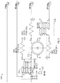
- FIG. 5 shows a schematic diagram of a 3-stage, unconditionally stable VGA for use in a vector modulator implemented as in FIG. 1 in accordance with various examples.
- VGA 500 is a single VGA that can be implemented into one of the four VGAs in VGA stage 108 of FIG. 1 .
- VGA 500 is a 3-stage VGA implemented with 3 PAs 502 - 506 that are designed with 2 ⁇ 30 ⁇ m GaN pseudomorphic-High-Electron-Mobility-Transistors (“pHEMTs”).
- pHEMTs pseudomorphic-High-Electron-Mobility-Transistors
- Each PA has a gain of around 6 dB and is connected to a set of vias, such as vias 508 - 510 for PA 502 , vias 512 - 514 for PA 504 , and vias 516 - 518 for PA 506 .
- the PAs 502 - 506 are made unconditionally stable with the integration of stability network 520 .
- Stability network 520 has a transmission line and a radial stub 522 for impedance conjugate matching and to avoid instability issues.
- Stability network 520 also has a DC blocking capacitor 524 to filter out low frequencies and further improve stability.
- the combination of a transmission line, DC blocking capacitor 524 and radial stub 522 is effectively a high pass matching network topology. This matching network topology provides unconditional stability by filtering out DC and lower RF frequencies by selecting appropriate capacitance values for the DC blocking capacitor 524 and dimensions for the radial stub 522 .
- DC blocking capacitors 526 and 528 are also incorporated in the VGA 500 before PAs 504 and 506 , respectively.
- An additional DC blocking capacitor 530 is included after PA 506 .
- the DC blocking capacitors 524 - 528 all provide better stability and result in lower return losses in the VGA 500 .
- FIG. 6 illustrates the return losses and amplifier gain indicated by the S parameters in graph 600 and the K factor over mm-wave frequencies of interest in graph 602 .
- graph 600 shows an amplifier gain of around 20 dB
- graph 602 shows a K factor>1.
- the unconditionally stability, high gain and low return loss of the VGA 500 enables a vector modulator implemented as in FIG. 1 to achieve its desired phase shifts in a 360° range, while providing amplitude gains at mm-wave frequencies in applications as varied as wireless communications and autonomous driving.
- the high gain of the VGA 500 enables the VGA stage 108 to achieve the full 360° phase range at a good resolution while minimizing loss through the circuit.
- VGA 108 may have different operating modes, such as two of its four VGAs may operate together, while the other two are turned off.
- the high gain of each VGA 500 enables the final output signal in VGA stage 108 , which is a vector sum of the amplification and attenuation of the four individual VGA branches, to have an overall constant high gain and amplitude.
- the VGA stage 108 has four VGAs that may be implemented as in the example of FIG. 5 to output four amplified quadrature RF signals.
- the four signals are combined by the 4-way power combiner 110 .
- the 4-way power combiner 110 may be implemented as a Wilkinson power combiner.
- the 4-way power combiner 110 may have different desired configurations, e.g., reactive splitters, hybrid splitters, etc.
- An example Wilkinson power combiner is illustrated in FIG. 7 .
- Power combiner 700 is a 4-way Wilkinson power combiner with 4 ports matched to 50 ohms at a loss of around 8 dB.
- FIG. 8 illustrates a Smith chart 800 and a graph 802 showing the losses at a mm-wave frequency of 78.5 GHz.
- FIG. 9 illustrates a schematic diagram of a PA for use in a final amplifier stage implemented as in FIG. 1 and in accordance with various examples.
- PA 900 is designed with three main circuit structures to compensate for losses in the earlier circuit structures of vector modulator architecture 100 and provide further amplification gain: (1) a 3-stage, unconditionally stable VGA 902 ; (2) a bypass capacitor stage 904 ; and (3) a PA stage 906 .
- the VGA 902 may be implemented as in FIG. 5 to provide an amplification gain with low return losses while achieving unconditional stability.
- the bypass capacitor stage 904 includes 3 bypass capacitors 908 - 912 to provide stability in the bias line network in the VGA 902 , e.g., in bias line 914 .
- the PA stage 906 includes a single 4 ⁇ 50 ⁇ m GaN pHEMT device 916 with a blocking capacitor 918 .
- PA stage 906 is a small high pass filtering stage for further stability, matching and power gain.
- the total gain, efficiency and output power from the PA 900 are shown in graph 1000 in FIG. 10 .
- PA 900 results in a total power output of around 23.2 dBm, a gain of around 25 dB and a Power Added Efficiency (“PAE”) of around 8%.
- PAE Power Added Efficiency
- Use of a PA 900 together with a vector modulator 102 as in FIG. 1 enables phase shifts across a 360° range at a gain of 25-30 dB to be realized in a stable circuit at mm-wave frequencies.
- the resulting architecture illustrated in a layout in FIG. 11 can be manufactured in a 2.5 mm ⁇ 4.8 mm board 1100 for use in many mm-wave applications, including in wireless communications and autonomous driving.
- FIGS. 12 and 13 illustrate performance results for an example vector modulator architecture implemented as in FIG. 1 .
- FIG. 12 shows the phase performance in graphs 1200 - 1206
- FIG. 13 shows the gain performance in graphs 1300 - 1306 .
- the straight line shown in graphs 1200 - 1206 and 1300 - 1306 represent control voltages and the curves in the graphs represent the various phase shifts and amplifier gains that can be achieved at different gate bias voltages.
- phase shifts across a 360° range and amplifier gains in the 25-30 dB range are achievable with the vector modulator architecture described herein.
- the vector modulator architecture is suitable to many mm-wave applications, including in wireless communications and in autonomous vehicles.
- the vector modulator architecture may be applicable, for example, in a radar in an autonomous vehicle to achieve beam steering. Referring to FIG. 14 , an example environment in which a vector modulator architecture is implemented in a radar in an autonomous vehicle is described.
- Ego vehicle 1400 is an autonomous vehicle having a radar 1402 with an analog beamforming antenna employing a vector modulator architecture to achieve phase shifts in RF beams in a full FoV.
- radar 1402 can scan a 360° FoV to have a true 3D vision and human-like interpretation of the ego vehicle's path and surrounding environment.
- the analog beamforming antenna in radar 1402 radiates dynamically controllable and highly-directive RF beams.
- the RF beams reflect from targets in the vehicle's path and surrounding environment and the RF reflections are received by the radar 1402 for target detection and identification.
- radar 1402 generates a beam 1404 to detect vehicle 1406 , a beam 1408 to detect tree 1410 and a beam 1412 to detect bicycle 1414 .
- Each of the beams 1404 , 1408 and 1412 is generated with a set of parameters, such as beam width and phase.
- the phase of each beam is controlled by Phase Control Elements (“PCEs”) in the analog beamforming antenna in radar 1402 .
- PCEs Phase Control Elements
- a PCE may include a varactor, a set of varactors, a phase shift network, or a vector modulator architecture implemented as in FIG. 1 to achieve any desired phase shift from 0° to 360°.
- FIG. 15 shows a schematic diagram of an antenna module for use with a radar system implemented as in FIG. 14 and in accordance with various examples.
- Multi-Layer, Multi-Steering (“MLMS”) antenna module 1500 has an MLMS antenna system 1502 coupled to an antenna controller 1504 , a central processor 1506 , and a transceiver 1508 .
- a transmission signal controller 1510 generates a transmission signal, such as an FMCW signal, which is used for radar sensor applications as the transmitted signal is modulated in frequency, or phase.
- the FMCW signal enables a radar to measure range to a target by measuring the phase differences in phase or frequency between the transmitted signal and the received or reflected signal.
- FMCW formats there are a variety of modulation patterns that may be used within FMCW, including triangular, sawtooth, rectangular and so forth, each having advantages and purposes.
- sawtooth modulation may be selected for use when detection involves large distances to a target, i.e., long range.
- the shape of the wave form provides speed and velocity information based on the Doppler shift between signals. This information enables construction of a range-Doppler map to indicate a location and movement of a detected object.
- a target is any object detected by the radar, but may also refer to a specific type of object, e.g., a vehicle, a person, a road sign, and so on.
- the MLMS antenna module 1500 is applicable in a wireless communication or cellular system, implementing user tracking from a base station, fixed wireless location, and so forth, or function as a wireless relay to provide expanded coverage to users in a wireless network.
- the transmission signal in cellular communications is a coded signal, such as a cellular modulated Orthogonal Frequency Division Multiplexed (“OFDM”) signal.
- OFDM Orthogonal Frequency Division Multiplexed
- the MLMS antenna system 1502 radiates the signal through a structure consisting of four main layers: (1) connector and transition layer 1516 ; (2) power divider layer 1518 ; (3) RFIC layer 1520 ; and (4) antenna layer 1522 .
- the connector and transition layer 1516 couples the transmission signal from the transmission signal controller 1510 to the PCB for transmission to the power divider layer 1518 .
- the power divider layer 1518 is a corporate feed structure having a plurality of transmission lines for transmitting the signal to the antenna layer 1522 .
- the antenna layer 1522 includes a plurality of radiating slots for radiating the signal into the air. The slots are configured in a specific pattern as described below, but other patterns, shapes, dimensions, orientations and specifications may be used to achieve a variety of radiation patterns.
- the RFIC layer 1520 includes phase shifters (e.g., a vector modulator architecture) to achieve any desired phase shift from 0° to 360°.
- the RFIC layer 1520 also includes transitions from the power divider layer 1518 to the RFIC layer 1520 and from the RFIC layer 1520 to the antenna layer 1522 .
- an MLMS antenna module 1500 may have multiple MLMS antenna systems in any given configuration.
- a set of MLMS antennas may be designated as transmit antennas, and another set may be designated as receive antennas.
- an MLMS antenna may be orthogonal from another. Different MLMS antennas may also have different polarizations.
- different MLMS antennas may be configured to detect different targets, e.g., a set of antennas may be configured to enhance the detection and identification of pedestrians, another set of antennas may be configured to enhance the detection and identification of vehicles, and so forth.
- the configuration of the antennas may include power amplifiers to adjust the power of a transmitted signal and/or different polarization modes for different arrays to enhance pedestrian detection. It is appreciated that numerous configurations of MLMS antennas may be implemented in a given antenna module.
- the antenna controller 1504 receives information from other modules in the radar (e.g., a perception or AI module) indicating a next radiation beam, wherein a radiation beam may be specified by parameters such as beam width, transmit angle, transmit direction and so forth.
- the antenna controller 1504 determines a voltage matrix to apply to reactance control mechanisms in the MLMS antenna system 1502 to achieve a given phase shift or other parameters.
- Transceiver 1508 prepares a signal for transmission, such as a signal for a radar device, wherein the signal is defined by modulation and frequency.
- the signal is received by the MLMS antenna system 1502 and the desired phase of the radiated signal is adjusted at the direction of the antenna controller 1504 .
- the MLMS antenna system 1502 can be implemented in many applications, including radar, cellular antennas, and autonomous vehicles to detect and identify targets in the path of or surrounding the vehicle. Alternate examples may use the MLMS antenna for wireless communications, medical equipment, sensing, monitoring, and so forth. Each application type incorporates designs and configurations of the elements, structures and modules described herein to accommodate their needs and goals.
- a signal is specified by antenna controller 1504 , which may be at the direction of a perception or AI module in the radar, a sensor fusion module via interface to sensor fusion 1514 , or it may be based on program information from memory storage 1512 . There are a variety of considerations to determine the beam formation, wherein this information is provided to antenna controller 1504 to configure the various elements of the MLMS antenna system 1502 .
- the transmission signal controller 1510 generates the transmission signal and provides it to the MLMS antenna system 1502 , such as through a coaxial cable or other connector. The signal propagates through the connector and transition layer 1516 to the antenna layer 1522 for transmission through the air.
- the antenna layer 1522 may be referred to as a type of slotted waveguide antenna (“SWA”), wherein the power divider layer 1516 acts as a feed to the antenna layer 1522 .
- SWA slotted waveguide antenna
- Alternate examples may reconfigure and/or modify the antenna structure to improve radiation patterns, bandwidth, side lobe levels, and so forth.
- the antenna performance may be adjusted by design of the antenna's features and materials, such the shape of the slots, slot patterns, slot dimensions, conductive trace materials and patterns, as well as other modifications to achieve impedance matching and so forth.
- FIG. 16 is a schematic diagram of an antenna system for use with the antenna of FIG. 15 in accordance with various examples.
- the antenna system 1600 has a connector 1602 and transition 1604 in a connector and transition layer, a power divider layer 1606 , an RFIC layer with transitions 1608 - 1610 and phase shifters 1612 , and an antenna layer 1614 .
- Antenna system 1600 also has a Power Amplifier (“PA”) and a Low Noise Amplifier (“LNA”) module 1616 to boost the transmission signal coming from the connector 1602 before its split through the power divider layer 1606 .
- PA Power Amplifier
- LNA Low Noise Amplifier
- the power divider layer 1606 is a type of a power divider circuit such that it takes an input signal and divides it through a network of paths or transmission lines. Each path may have similar dimensions; however, the size of the paths may be configured to achieve a desired transmission and/or radiation result.
- the power divider layer 1606 is designed to be impedance-matched, such that the impedances at each end of a transmission line matches the characteristic impedance of the line.
- Each transmission line is bounded by a set of vias.
- the phase shifters 1612 are implemented with a vector modulator architecture described herein above. The vector modulator architecture enables phase shifts across a 360 range to be achieved with unconditionally stable PAs providing gains up to 25-30 dB at mm-wave frequencies of interest.
- the phrase “at least one of” preceding a series of items, with the terms “and” or “or” to separate any of the items, modifies the list as a whole, rather than each member of the list (i.e., each item).
- the phrase “at least one of” does not require selection of at least one item; rather, the phrase allows a meaning that includes at least one of any one of the items, and/or at least one of any combination of the items, and/or at least one of each of the items.
- phrases “at least one of A, B, and C” or “at least one of A, B, or C” each refer to only A, only B, or only C; any combination of A, B, and C; and/or at least one of each of A, B, and C.
Landscapes
- Engineering & Computer Science (AREA)
- Power Engineering (AREA)
- Microelectronics & Electronic Packaging (AREA)
- Computer Networks & Wireless Communication (AREA)
- Signal Processing (AREA)
- Radar Systems Or Details Thereof (AREA)
Abstract
Description
Claims (19)
Priority Applications (1)
| Application Number | Priority Date | Filing Date | Title |
|---|---|---|---|
| US16/575,207 US11336237B2 (en) | 2018-09-24 | 2019-09-18 | Vector modulator for millimeter wave applications |
Applications Claiming Priority (2)
| Application Number | Priority Date | Filing Date | Title |
|---|---|---|---|
| US201862735550P | 2018-09-24 | 2018-09-24 | |
| US16/575,207 US11336237B2 (en) | 2018-09-24 | 2019-09-18 | Vector modulator for millimeter wave applications |
Publications (2)
| Publication Number | Publication Date |
|---|---|
| US20200099350A1 US20200099350A1 (en) | 2020-03-26 |
| US11336237B2 true US11336237B2 (en) | 2022-05-17 |
Family
ID=69885690
Family Applications (1)
| Application Number | Title | Priority Date | Filing Date |
|---|---|---|---|
| US16/575,207 Active 2039-12-03 US11336237B2 (en) | 2018-09-24 | 2019-09-18 | Vector modulator for millimeter wave applications |
Country Status (1)
| Country | Link |
|---|---|
| US (1) | US11336237B2 (en) |
Cited By (1)
| Publication number | Priority date | Publication date | Assignee | Title |
|---|---|---|---|---|
| US12348257B2 (en) | 2022-03-07 | 2025-07-01 | Samsung Electronics Co., Ltd. | Electronic device for controlling wireless transmission and operating method thereof |
Families Citing this family (3)
| Publication number | Priority date | Publication date | Assignee | Title |
|---|---|---|---|---|
| US12381316B2 (en) * | 2019-07-08 | 2025-08-05 | Tubis Technology Inc. | Frequency tunable bi-directional active phased-array processing |
| US11075667B1 (en) * | 2020-03-09 | 2021-07-27 | Kabushiki Kaisha Toshiba | Tuneable rat-race coupler for single antenna full duplex |
| CN116960596A (en) * | 2023-09-19 | 2023-10-27 | 成都华兴大地科技有限公司 | A W-band power combiner based on vector modulation |
Citations (10)
| Publication number | Priority date | Publication date | Assignee | Title |
|---|---|---|---|---|
| US6492949B1 (en) | 2000-08-16 | 2002-12-10 | Raytheon Company | Slot antenna element for an array antenna |
| US7756491B2 (en) * | 2006-08-04 | 2010-07-13 | Axiom Microdevices, Inc. | Phase shifter |
| US20110175789A1 (en) | 2009-11-09 | 2011-07-21 | Rayspan Corporation | Rf module and antenna systems |
| US8452251B2 (en) * | 2009-04-13 | 2013-05-28 | Viasat, Inc. | Preselector amplifier |
| US20140347234A1 (en) | 2011-01-13 | 2014-11-27 | Polyvalor, Limited Partnership | Polarization-diverse antennas and systems |
| US8922347B1 (en) | 2009-06-17 | 2014-12-30 | L. Pierre de Rochemont | R.F. energy collection circuit for wireless devices |
| US9236892B2 (en) | 2013-03-15 | 2016-01-12 | Dockon Ag | Combination of steering antennas, CPL antenna(s), and one or more receive logarithmic detector amplifiers for SISO and MIMO applications |
| US20160134022A1 (en) | 2010-04-11 | 2016-05-12 | Broadcom Corporation | Programmable antenna having a programmable substrate |
| US9905928B2 (en) | 2005-06-30 | 2018-02-27 | L. Pierre de Rochemont | Electrical components and method of manufacture |
| US10367463B2 (en) * | 2016-06-09 | 2019-07-30 | Keysight Technologies, Inc. | Variable gain distributed amplifier systems and methods |
-
2019
- 2019-09-18 US US16/575,207 patent/US11336237B2/en active Active
Patent Citations (10)
| Publication number | Priority date | Publication date | Assignee | Title |
|---|---|---|---|---|
| US6492949B1 (en) | 2000-08-16 | 2002-12-10 | Raytheon Company | Slot antenna element for an array antenna |
| US9905928B2 (en) | 2005-06-30 | 2018-02-27 | L. Pierre de Rochemont | Electrical components and method of manufacture |
| US7756491B2 (en) * | 2006-08-04 | 2010-07-13 | Axiom Microdevices, Inc. | Phase shifter |
| US8452251B2 (en) * | 2009-04-13 | 2013-05-28 | Viasat, Inc. | Preselector amplifier |
| US8922347B1 (en) | 2009-06-17 | 2014-12-30 | L. Pierre de Rochemont | R.F. energy collection circuit for wireless devices |
| US20110175789A1 (en) | 2009-11-09 | 2011-07-21 | Rayspan Corporation | Rf module and antenna systems |
| US20160134022A1 (en) | 2010-04-11 | 2016-05-12 | Broadcom Corporation | Programmable antenna having a programmable substrate |
| US20140347234A1 (en) | 2011-01-13 | 2014-11-27 | Polyvalor, Limited Partnership | Polarization-diverse antennas and systems |
| US9236892B2 (en) | 2013-03-15 | 2016-01-12 | Dockon Ag | Combination of steering antennas, CPL antenna(s), and one or more receive logarithmic detector amplifiers for SISO and MIMO applications |
| US10367463B2 (en) * | 2016-06-09 | 2019-07-30 | Keysight Technologies, Inc. | Variable gain distributed amplifier systems and methods |
Non-Patent Citations (7)
| Title |
|---|
| A. Babakhani et al.,"Transmitter Architectures Based on Near-Field Direct Antenna Modulation," in IEEE Journal of Solid-State Circuits, vol. 43, No. 12, pp. 2674-2692, Dec. 2008. |
| A. S. Tehrani, H. M. Nemati, H. Cao, T. Eriksson and C. Fager, "Dynamic load modulation of high power amplifiers with varactor-based matching networks," 2009 IEEE MTT-S International Microwave Symposium Digest, pp. 1537-1540. 2009. |
| E.A. Firouzjaei, "mm-Wave Phase Shifters and Switches," Technical Report No. UCB/EECS-2010-163, Electrical Engineering and Computer Sciences, University of California at Berkeley, Berkeley, CA, USA, Dec. 2010. |
| F. Raab, et al., "Power Amplifiers and Transmitters for RF and Microwave," IEEE Transactions on Microwave Theory and Techniques, vol. 50, No. 3, pp. 814-826, 2002. |
| Mohamed Elkhouly et al., "220-250-GHz Phased-Array Circuits in 0.13-um SiGe BiCMOS Technology" IEEE Transactions on Microwave Theory and Techniques, vol. 61, No. 8, pp. 3115-3127, Aug. 2013. |
| P. James et al., "Design of a Multiport Amplifier Beam Forming Network for a Mobile Communications Antenna," EADS Astrium, UK Roke Manor Research Ltd., Romsey, pp. 1-12. |
| P. James, "The RF Modelling of a Ku-band Multi-port Amplifier," esa Airbus Defence and Space, UK, pp. 1-8. |
Cited By (1)
| Publication number | Priority date | Publication date | Assignee | Title |
|---|---|---|---|---|
| US12348257B2 (en) | 2022-03-07 | 2025-07-01 | Samsung Electronics Co., Ltd. | Electronic device for controlling wireless transmission and operating method thereof |
Also Published As
| Publication number | Publication date |
|---|---|
| US20200099350A1 (en) | 2020-03-26 |
Similar Documents
| Publication | Publication Date | Title |
|---|---|---|
| US11711108B2 (en) | Universal transmit/receive module for radar and communications | |
| US11688943B2 (en) | Radiation pattern reconfigurable antenna | |
| US12107558B2 (en) | Combining power amplifers at milimeter wave frequencies | |
| US11336237B2 (en) | Vector modulator for millimeter wave applications | |
| US20250362380A1 (en) | Millimeter wave automotive radar systems | |
| US8188904B2 (en) | RF circuit with improved antenna matching | |
| EP2741422B1 (en) | A concurrent multiband transceiver | |
| US11515630B2 (en) | Dynamic supply modulation power amplifier architecture for millimeter wave applications | |
| US20030112184A1 (en) | Single ku-band multi-polarization gallium arsenide transmit chip | |
| JPH06510127A (en) | Transmit/receive module | |
| US9106314B2 (en) | Concurrent multiband transceiver | |
| KR102415957B1 (en) | Antenna array and radar device using thereof | |
| US20220109220A1 (en) | Power splitter-combiner circuits in 5g mm-wave beamformer architectures | |
| US20100156740A1 (en) | Leaky-wave dual-antenna system | |
| Ahmad et al. | BiCMOS IQ transceiver with array-on-chip for D-band joint radar-communication applications | |
| WO2025060774A1 (en) | Signal processing system and related apparatus | |
| CN119199760A (en) | A phased array radar jammer system with multi-beam reception and narrow beam transmission | |
| US20030020649A1 (en) | Continuous-wave radar with reflection-modulator | |
| JP2013026817A (en) | Phased array antenna | |
| JP2008249498A (en) | Radar system | |
| Kuwabara et al. | D-band 4-ch antenna-on-chip phased-array tx front-end | |
| US20240291533A1 (en) | D-band vector modulator phase-shifter with delay line-based differential quadrature generation |
Legal Events
| Date | Code | Title | Description |
|---|---|---|---|
| FEPP | Fee payment procedure |
Free format text: ENTITY STATUS SET TO UNDISCOUNTED (ORIGINAL EVENT CODE: BIG.); ENTITY STATUS OF PATENT OWNER: SMALL ENTITY |
|
| FEPP | Fee payment procedure |
Free format text: ENTITY STATUS SET TO SMALL (ORIGINAL EVENT CODE: SMAL); ENTITY STATUS OF PATENT OWNER: SMALL ENTITY |
|
| AS | Assignment |
Owner name: METAWAVE CORPORATION, CALIFORNIA Free format text: ASSIGNMENT OF ASSIGNORS INTEREST;ASSIGNOR:DANI, ASMITA;REEL/FRAME:051204/0313 Effective date: 20191204 |
|
| STPP | Information on status: patent application and granting procedure in general |
Free format text: DOCKETED NEW CASE - READY FOR EXAMINATION |
|
| STPP | Information on status: patent application and granting procedure in general |
Free format text: NON FINAL ACTION MAILED |
|
| STPP | Information on status: patent application and granting procedure in general |
Free format text: RESPONSE TO NON-FINAL OFFICE ACTION ENTERED AND FORWARDED TO EXAMINER |
|
| STPP | Information on status: patent application and granting procedure in general |
Free format text: FINAL REJECTION MAILED |
|
| STPP | Information on status: patent application and granting procedure in general |
Free format text: ADVISORY ACTION MAILED |
|
| STPP | Information on status: patent application and granting procedure in general |
Free format text: DOCKETED NEW CASE - READY FOR EXAMINATION |
|
| STPP | Information on status: patent application and granting procedure in general |
Free format text: NOTICE OF ALLOWANCE MAILED -- APPLICATION RECEIVED IN OFFICE OF PUBLICATIONS |
|
| AS | Assignment |
Owner name: BDCM A2 LLC, NEW JERSEY Free format text: SECURITY INTEREST;ASSIGNOR:METAWAVE CORPORATION;REEL/FRAME:059454/0555 Effective date: 20220314 |
|
| STPP | Information on status: patent application and granting procedure in general |
Free format text: PUBLICATIONS -- ISSUE FEE PAYMENT VERIFIED |
|
| STCF | Information on status: patent grant |
Free format text: PATENTED CASE |
|
| FEPP | Fee payment procedure |
Free format text: MAINTENANCE FEE REMINDER MAILED (ORIGINAL EVENT CODE: REM.); ENTITY STATUS OF PATENT OWNER: SMALL ENTITY |