US11334152B2 - Electronic device and content executing method using sight-line information thereof - Google Patents
Electronic device and content executing method using sight-line information thereof Download PDFInfo
- Publication number
- US11334152B2 US11334152B2 US16/652,089 US201816652089A US11334152B2 US 11334152 B2 US11334152 B2 US 11334152B2 US 201816652089 A US201816652089 A US 201816652089A US 11334152 B2 US11334152 B2 US 11334152B2
- Authority
- US
- United States
- Prior art keywords
- sight
- line
- user
- dynamic
- movement
- Prior art date
- Legal status (The legal status is an assumption and is not a legal conclusion. Google has not performed a legal analysis and makes no representation as to the accuracy of the status listed.)
- Active
Links
Images


Classifications
-
- H—ELECTRICITY
- H04—ELECTRIC COMMUNICATION TECHNIQUE
- H04N—PICTORIAL COMMUNICATION, e.g. TELEVISION
- H04N21/00—Selective content distribution, e.g. interactive television or video on demand [VOD]
- H04N21/40—Client devices specifically adapted for the reception of or interaction with content, e.g. set-top-box [STB]; Operations thereof
- H04N21/41—Structure of client; Structure of client peripherals
- H04N21/422—Input-only peripherals, i.e. input devices connected to specially adapted client devices, e.g. global positioning system [GPS]
- H04N21/4223—Cameras
-
- G—PHYSICS
- G06—COMPUTING OR CALCULATING; COUNTING
- G06F—ELECTRIC DIGITAL DATA PROCESSING
- G06F3/00—Input arrangements for transferring data to be processed into a form capable of being handled by the computer; Output arrangements for transferring data from processing unit to output unit, e.g. interface arrangements
- G06F3/01—Input arrangements or combined input and output arrangements for interaction between user and computer
- G06F3/011—Arrangements for interaction with the human body, e.g. for user immersion in virtual reality
- G06F3/013—Eye tracking input arrangements
-
- G—PHYSICS
- G06—COMPUTING OR CALCULATING; COUNTING
- G06F—ELECTRIC DIGITAL DATA PROCESSING
- G06F3/00—Input arrangements for transferring data to be processed into a form capable of being handled by the computer; Output arrangements for transferring data from processing unit to output unit, e.g. interface arrangements
- G06F3/01—Input arrangements or combined input and output arrangements for interaction between user and computer
- G06F3/011—Arrangements for interaction with the human body, e.g. for user immersion in virtual reality
-
- G—PHYSICS
- G06—COMPUTING OR CALCULATING; COUNTING
- G06F—ELECTRIC DIGITAL DATA PROCESSING
- G06F3/00—Input arrangements for transferring data to be processed into a form capable of being handled by the computer; Output arrangements for transferring data from processing unit to output unit, e.g. interface arrangements
- G06F3/01—Input arrangements or combined input and output arrangements for interaction between user and computer
- G06F3/016—Input arrangements with force or tactile feedback as computer generated output to the user
-
- G—PHYSICS
- G06—COMPUTING OR CALCULATING; COUNTING
- G06F—ELECTRIC DIGITAL DATA PROCESSING
- G06F3/00—Input arrangements for transferring data to be processed into a form capable of being handled by the computer; Output arrangements for transferring data from processing unit to output unit, e.g. interface arrangements
- G06F3/01—Input arrangements or combined input and output arrangements for interaction between user and computer
- G06F3/017—Gesture based interaction, e.g. based on a set of recognized hand gestures
-
- G—PHYSICS
- G06—COMPUTING OR CALCULATING; COUNTING
- G06F—ELECTRIC DIGITAL DATA PROCESSING
- G06F3/00—Input arrangements for transferring data to be processed into a form capable of being handled by the computer; Output arrangements for transferring data from processing unit to output unit, e.g. interface arrangements
- G06F3/01—Input arrangements or combined input and output arrangements for interaction between user and computer
- G06F3/048—Interaction techniques based on graphical user interfaces [GUI]
- G06F3/0481—Interaction techniques based on graphical user interfaces [GUI] based on specific properties of the displayed interaction object or a metaphor-based environment, e.g. interaction with desktop elements like windows or icons, or assisted by a cursor's changing behaviour or appearance
- G06F3/04812—Interaction techniques based on cursor appearance or behaviour, e.g. being affected by the presence of displayed objects
-
- G—PHYSICS
- G06—COMPUTING OR CALCULATING; COUNTING
- G06F—ELECTRIC DIGITAL DATA PROCESSING
- G06F3/00—Input arrangements for transferring data to be processed into a form capable of being handled by the computer; Output arrangements for transferring data from processing unit to output unit, e.g. interface arrangements
- G06F3/01—Input arrangements or combined input and output arrangements for interaction between user and computer
- G06F3/048—Interaction techniques based on graphical user interfaces [GUI]
- G06F3/0481—Interaction techniques based on graphical user interfaces [GUI] based on specific properties of the displayed interaction object or a metaphor-based environment, e.g. interaction with desktop elements like windows or icons, or assisted by a cursor's changing behaviour or appearance
- G06F3/04817—Interaction techniques based on graphical user interfaces [GUI] based on specific properties of the displayed interaction object or a metaphor-based environment, e.g. interaction with desktop elements like windows or icons, or assisted by a cursor's changing behaviour or appearance using icons
-
- G—PHYSICS
- G06—COMPUTING OR CALCULATING; COUNTING
- G06F—ELECTRIC DIGITAL DATA PROCESSING
- G06F3/00—Input arrangements for transferring data to be processed into a form capable of being handled by the computer; Output arrangements for transferring data from processing unit to output unit, e.g. interface arrangements
- G06F3/01—Input arrangements or combined input and output arrangements for interaction between user and computer
- G06F3/048—Interaction techniques based on graphical user interfaces [GUI]
- G06F3/0481—Interaction techniques based on graphical user interfaces [GUI] based on specific properties of the displayed interaction object or a metaphor-based environment, e.g. interaction with desktop elements like windows or icons, or assisted by a cursor's changing behaviour or appearance
- G06F3/0482—Interaction with lists of selectable items, e.g. menus
-
- G—PHYSICS
- G06—COMPUTING OR CALCULATING; COUNTING
- G06F—ELECTRIC DIGITAL DATA PROCESSING
- G06F3/00—Input arrangements for transferring data to be processed into a form capable of being handled by the computer; Output arrangements for transferring data from processing unit to output unit, e.g. interface arrangements
- G06F3/01—Input arrangements or combined input and output arrangements for interaction between user and computer
- G06F3/048—Interaction techniques based on graphical user interfaces [GUI]
- G06F3/0484—Interaction techniques based on graphical user interfaces [GUI] for the control of specific functions or operations, e.g. selecting or manipulating an object, an image or a displayed text element, setting a parameter value or selecting a range
- G06F3/04842—Selection of displayed objects or displayed text elements
-
- H—ELECTRICITY
- H04—ELECTRIC COMMUNICATION TECHNIQUE
- H04N—PICTORIAL COMMUNICATION, e.g. TELEVISION
- H04N21/00—Selective content distribution, e.g. interactive television or video on demand [VOD]
- H04N21/40—Client devices specifically adapted for the reception of or interaction with content, e.g. set-top-box [STB]; Operations thereof
- H04N21/41—Structure of client; Structure of client peripherals
- H04N21/422—Input-only peripherals, i.e. input devices connected to specially adapted client devices, e.g. global positioning system [GPS]
- H04N21/42201—Input-only peripherals, i.e. input devices connected to specially adapted client devices, e.g. global positioning system [GPS] biosensors, e.g. heat sensor for presence detection, EEG sensors or any limb activity sensors worn by the user
-
- H—ELECTRICITY
- H04—ELECTRIC COMMUNICATION TECHNIQUE
- H04N—PICTORIAL COMMUNICATION, e.g. TELEVISION
- H04N21/00—Selective content distribution, e.g. interactive television or video on demand [VOD]
- H04N21/40—Client devices specifically adapted for the reception of or interaction with content, e.g. set-top-box [STB]; Operations thereof
- H04N21/43—Processing of content or additional data, e.g. demultiplexing additional data from a digital video stream; Elementary client operations, e.g. monitoring of home network or synchronising decoder's clock; Client middleware
- H04N21/442—Monitoring of processes or resources, e.g. detecting the failure of a recording device, monitoring the downstream bandwidth, the number of times a movie has been viewed, the storage space available from the internal hard disk
- H04N21/44213—Monitoring of end-user related data
- H04N21/44218—Detecting physical presence or behaviour of the user, e.g. using sensors to detect if the user is leaving the room or changes his face expression during a TV programme
-
- H—ELECTRICITY
- H04—ELECTRIC COMMUNICATION TECHNIQUE
- H04N—PICTORIAL COMMUNICATION, e.g. TELEVISION
- H04N21/00—Selective content distribution, e.g. interactive television or video on demand [VOD]
- H04N21/40—Client devices specifically adapted for the reception of or interaction with content, e.g. set-top-box [STB]; Operations thereof
- H04N21/47—End-user applications
- H04N21/482—End-user interface for programme selection
- H04N21/4821—End-user interface for programme selection using a grid, e.g. sorted out by channel and broadcast time
Definitions
- Various embodiments of the disclosure relate to a method for executing content by using sight-line information and an electronic device thereof.
- Electronic devices can provide various functions.
- the smart phone can provide a short-range wireless communication (e.g., Bluetooth, wireless fidelity (WiFi), near field communication (NFC), etc.), a mobile communication (e.g., 3-generation (3G)), 4G, 5G, etc.), a music or video reproduction function, a photographing function, a navigation function, a messenger function, etc.
- a short-range wireless communication e.g., Bluetooth, wireless fidelity (WiFi), near field communication (NFC), etc.
- a mobile communication e.g., 3-generation (3G)), 4G, 5G, etc.
- 3G 3-generation
- 4G 4G
- 5G etc.
- the electronic devices can include various input interfaces.
- the electronic devices can include an input device such as a mouse, a track ball, a keyboard, a button key, a touch screen, an electronic pen, and/or the like.
- the electronic devices can execute content according to various inputs of a user. For example, in response to content being double clicked through a mouse or being touched through a touch tool (e.g., a finger, a stylus, an electronic pen, etc.), the electronic devices can execute the corresponding content.
- a touch tool e.g., a finger, a stylus, an electronic pen, etc.
- the electronic device having the sight-line tracking function is providing various functions by using sight-line information. For example, the electronic device does not turn off a screen while a user is looking at the screen, or can execute a corresponding content in response to the user staring at an icon for a specific time or more.
- a conventional content execution method using sight-line information has an inconvenience that a user has to stare at, during a pre-designated time (e.g., 2 seconds), a content (e.g., an icon, a thumbnail image, etc.) intended to be executed, and is not able to move a sight-line to another location before execution is completed.
- a pre-designated time e.g. 2 seconds
- the conventional content execution method using the sight-line information has an inconvenience that, even in response to the user simply looking at content without an intention of executing the content, the content is executed in response to the lapse of the pre-designated time.
- Various embodiments of the disclosure for solving the aforementioned problems may provide an electronic device capable of fast and efficiently executing content by using only sight-line information, and a content execution method using the sight-line information thereof.
- an electronic device may include a display, a sight-line tracking module, a memory storing instructions, and at least one processor operatively coupled with the display, the sight-line tracking module and the memory.
- the at least one processor may, on the basis of execution of the instructions, be configured to: control the display to display at least one content, and identify a content that a user stares at among the at least one content, based on user's sight-line information tracked through the sight-line tracking module, and in response to a sight-line movement on the identified content being sensed, display, on the display, a dynamic user interface (UI) that is dynamically varied according to the sight-line movement, and in response to a path of the user's sight-line movement satisfying a pre-designated condition, execute the identified content.
- UI dynamic user interface
- a method for executing content by using sight-line information of an electronic device may include displaying at least one content on a display, and identifying a content that a user stares at among the at least one content, and in response to a user's sight-line movement on the identified content being sensed, displaying, on the display, a UI that is dynamically varied according to the sight-line movement, and in response to a path of the user's sight-line movement satisfying a pre-designated condition, execute the identified content.
- Various embodiments of the disclosure may efficiently control the execution of content by using sight-line information. For example, in various embodiments of the disclosure, a user may move a sight-line fast or slowly, to control an execution speed of content.
- various embodiments of the disclosure do not immediately cancel a command of execution of content even though the sight-line deviates temporarily and thus, may prevent an inconvenience in which, regardless of a user's intention, the content execution is canceled in response to the sight-line temporarily deviating.
- various embodiments of the disclosure may execute content by using only sight-line information and thus, do not require a separate input device.
- various embodiments of the disclosure execute the content by a movement of a sight-line and thus, may solve a conventional inconvenience in which the content is executed in response to simply staring at the content without an intention to execute the content.
- various embodiments of the disclosure may perform another function according to a movement direction of the sight-line and thus, may easily execute various functions related with content.
- FIG. 1 is a block diagram of an electronic device within a network environment according to various embodiments.
- FIG. 2 is a block diagram illustrating a construction of an electronic device according to an embodiment of the disclosure.
- FIG. 3 is a flowchart explaining a method for executing content by using sight-line information of an electronic device according to an embodiment of the disclosure.
- FIG. 4A to FIG. 4E are diagrams explaining a variation of a dynamic UI dependent on a sight-line movement of an electronic device according to an embodiment of the disclosure.
- FIG. 5 is a flowchart explaining a method for executing content by using sight-line information of an electronic device according to an embodiment of the disclosure.
- FIG. 6A and FIG. 6B are diagrams explaining a display position of a notification UI notifying an execution waiting state of content according to an embodiment of the disclosure.
- FIG. 6C is a diagram explaining a variation of a dynamic UI dependent on a sight-line movement of an electronic device according to an embodiment of the disclosure.
- FIG. 7A to FIG. 7H are example diagrams executing a file by using sight-line information of an electronic device according to an embodiment of the disclosure.
- FIG. 8A to FIG. 8F are example diagrams executing an image by using sight-line information of an electronic device according to an embodiment of the disclosure.
- FIG. 9A to FIG. 9C are example diagrams executing an application by using sight-line direction information of an electronic device according to an embodiment of the disclosure.
- FIG. 10A to FIG. 10G are example diagrams executing content by using sight-line information in a three-dimensional space according to an embodiment of the disclosure.
- FIG. 1 is a block diagram illustrating an electronic device 101 in a network environment 100 according to various embodiments.
- the electronic device 101 in the network environment 100 may communicate with an electronic device 102 via a first network 198 (e.g., a short-range wireless communication), or an electronic device 104 or a server 108 via a second network 199 (e.g., a long-range wireless communication).
- the electronic device 101 may communicate with the electronic device 104 via the server 108 .
- the electronic device may include a processor 120 , memory 130 , an input device 150 , a sound output device 155 , a display device 160 , an audio module 170 , a sensor module 176 , an interface 177 , a haptic module 179 , a camera module 180 , a power management module 188 , a battery 189 , a communication module 190 , a subscriber identification module (SIM) 196 , and an antenna module 197 .
- at least one (e.g., the display device 160 or the camera module 180 ) of the components may be omitted from the electronic device 101 , or other components may be added in the electronic device 101 .
- the components may be integrated and implemented such as the sensor module 176 (e.g., a fingerprint sensor, an iris sensor, or an illuminance sensor) embedded in the display device 160 (e.g., a display).
- the sensor module 176 e.g., a fingerprint sensor, an iris sensor, or an illuminance sensor
- the display device 160 e.g., a display
- the processor 120 may execute, for example, software (e.g., a program 140 ) to control at least one other component (e.g., a hardware or software component) of the electronic device 101 coupled with the processor 120 , and may perform various data processing and computation.
- the processor 120 may load and process a command or data received from another component (e.g., the sensor module 176 or the communication module 190 ) in volatile memory 132 , and store resulting data in non-volatile memory 134 .
- the processor 120 may include a main processor 121 (e.g., a central processing unit (CPU) or an application processor (AP)), and an auxiliary processor 123 (e.g., a graphics processing unit (GPU), an image signal processor (ISP), a sensor hub processor, or a communication processor (CP)) that is operable independently from the main processor 121 , may additionally or alternatively consume less power than the main processor 121 , or to be specific to a specified function.
- the auxiliary processor 123 may be implemented as separate from, or embedded in the main processor 121 .
- the auxiliary processor 123 may control at least some of functions or states related to at least one component (e.g., the display device 160 , the sensor module 176 , or the communication module 190 ) among the components of the electronic device 101 , instead of the main processor 121 while the main processor 121 is in an inactive (e.g., sleep) state, or together with the main processor 121 while the main processor 121 is in an active state (e.g., performing an application).
- the auxiliary processor 123 e.g., an image signal processor or a communication processor
- the memory 130 may store various data used by at least one component (e.g., the processor 120 or the sensor module 176 ) of the electronic device 101 .
- the various data may include, for example, software (e.g., the program 140 ) and input data or output data for a command related thererto.
- the memory 130 may include the volatile memory 132 or the non-volatile memory 134 .
- the program 140 may be stored in the memory 130 as software, and may include, for example, an operating system (OS) 142 , middleware 144 , or an application 146 .
- OS operating system
- middleware middleware
- application application
- the input device 150 may receive a command or data to be used by other component (e.g., the processor 120 ) of the electronic device 101 , from the outside (e.g., a user) of the electronic device 101 .
- the input device 150 may include, for example, a microphone, a mouse, or a keyboard.
- the sound output device 155 may output sound signals to the outside of the electronic device 101 .
- the sound output device 155 may include, for example, a speaker or a receiver.
- the speaker may be used for general purposes, such as playing multimedia or playing record, and the receiver may be used for an incoming calls. According to an embodiment, the receiver may be implemented as separate from, or as part of the speaker.
- the display device 160 may visually provide information to a user of the electronic device 101 .
- the display device 160 may include, for example, a display, a hologram device, or a projector and control circuitry to control a corresponding one of the display, hologram device, and projector.
- the display device 160 may include touch circuitry, or a pressure sensor adapted to measure the intensity of force incurred by the touch.
- the audio module 170 may convert a sound into an electrical signal and vice versa. According to an embodiment, the audio module 170 may obtain the sound via the input device 150 , or output the sound via the sound output device 155 or an external electronic device (e.g., an electronic device 102 (e.g., a speaker or a headphone)) wiredly or wirelessly coupled with the electronic device 101 .
- an electronic device 102 e.g., a speaker or a headphone
- the sensor module 176 may generate an electrical signal or data value corresponding to an operational state (e.g., power or temperature) of the electronic device 101 or an environmental state external to the electronic device 101 .
- the sensor module 176 may include, for example, a gesture sensor, a gyro sensor, an atmospheric pressure sensor, a magnetic sensor, an acceleration sensor, a grip sensor, a proximity sensor, a color sensor, an infrared (IR) sensor, a biometric sensor, a temperature sensor, a humidity sensor, or an illuminance sensor.
- the interface 177 may support a specified protocol for coupling with the external electronic device (e.g., the electronic device 102 ) wiredly or wirelessly.
- the interface 177 may include a high definition multimedia interface (HDMI), a universal serial bus (USB) interface, a secure digital (SD) card interface, or an audio interface.
- HDMI high definition multimedia interface
- USB universal serial bus
- SD secure digital
- a connecting terminal 178 may include a connector via which the electronic device 101 may be physically connected with the external electronic device (e.g., the electronic device 102 ).
- the connecting terminal 178 may include, for example, a HDMI connector, a USB connector, a SD card connector, or an audio connector (e.g., a headphone connector).
- the haptic module 179 may convert an electrical signal into a mechanical stimulus (e.g., a vibration or a movement) or electrical stimulus which may be recognized by a user via his tactile sensation or kinesthetic sensation.
- the haptic module 179 may include, for example, a motor, a piezoelectric element, or an electric stimulator.
- the camera module 180 may capture a still image or moving images.
- the camera module 180 may include one or more lense, image sensor, image signal processor, or flash.
- the power management module 188 may manage power supplied to the electronic device 101 .
- the power management module 188 may be implemented as at least part of, for example, a power management integrated circuit (PMIC).
- PMIC power management integrated circuit
- the battery 189 may supply power to at least one component of the electronic device 101 .
- the battery 189 may include, for example, a primary cell which is not rechargeable, a secondary cell which is rechargeable, or a fuel cell.
- the communication module 190 may support establishing a wired communication channel or a wireless communication channel between the electronic device 101 and the external electronic device (e.g., the electronic device 102 , the electronic device 104 , or the server 108 ) and performing communication via the established communication channel.
- the communication module 190 may include one or more communication processors that are operable independently from the processor 120 (e.g., the application processor (AP)) and supports a wired communication or a wireless communication.
- the processor 120 e.g., the application processor (AP)
- the communication module 190 may include a wireless communication module 192 (e.g., a cellular communication module, a short-range wireless communication module, or a global navigation satellite system (GNSS) communication module) or a wired communication module 194 (e.g., a local area network (LAN) communication module or a power line communication (PLC) module).
- a wireless communication module 192 e.g., a cellular communication module, a short-range wireless communication module, or a global navigation satellite system (GNSS) communication module
- GNSS global navigation satellite system
- wired communication module 194 e.g., a local area network (LAN) communication module or a power line communication (PLC) module.
- LAN local area network
- PLC power line communication
- a corresponding one of these communication modules may communicate with the external electronic device via the first network 198 (e.g., a short-range communication network, such as BluetoothTM, wireless-fidelity (Wi-Fi) direct, or infrared data association (IrDA)) or the second network 199 (e.g., a long-range communication network, such as a cellular network, the Internet, or a computer network (e.g., LAN or wide area network (WAN)).
- first network 198 e.g., a short-range communication network, such as BluetoothTM, wireless-fidelity (Wi-Fi) direct, or infrared data association (IrDA)
- the second network 199 e.g., a long-range communication network, such as a cellular network, the Internet, or a computer network (e.g., LAN or wide area network (WAN)
- These various types of communication modules may be implemented as a single chip, or may be implemented as multi chips separate from each other.
- the wireless communication module 192 may identify and authenticate the electronic device 101 in a communication network using subscriber information stored in the subscriber identification module 196 .
- the antenna module 197 may include one or more antennas to transmit or receive a signal or power to or from the outside.
- the communication module 190 e.g., the wireless communication module 192
- Some of the above-described components may be coupled mutually and communicate signals (e.g., commands or data) therebetween via an inter-peripheral communication scheme (e.g., a bus, general purpose input/output (GPIO), serial peripheral interface (SPI), or mobile industry processor interface (MIPI)).
- an inter-peripheral communication scheme e.g., a bus, general purpose input/output (GPIO), serial peripheral interface (SPI), or mobile industry processor interface (MIPI)
- commands or data may be transmitted or received between the electronic device 101 and the external electronic device 104 via the server 108 coupled with the second network 199 .
- Each of the electronic devices 102 and 104 may be a device of a same type as, or a different type, from the electronic device 101 .
- all or some of operations to be executed at the electronic device 101 may be executed at one or more of the external electronic devices.
- the electronic device 101 if the electronic device 101 should perform a function or a service automatically, or by a request, the electronic device 101 , instead of, or in addition to, executing the function or the service, may request at least part associated with the function or the service to external electronic devices.
- the external electronic devices receiving the request may perform the function requested, or an additional function, and transfer an outcome of the performing to the electronic device 101 .
- the electronic device may provide the outcome, with or without further processing of the outcome.
- a cloud computing, distributed computing, or client-server computing technology may be used, for example.
- FIG. 2 is a block diagram illustrating a construction of an electronic device according to an embodiment of the disclosure.
- the electronic device 200 may be one of a non-portable electronic device such as a personal computer (PC), a television (TV), etc. capable of tracking a user's sight-line, a portable electronic device such as a smart phone, a tablet PC, a notebook, etc., or a wearable electronic device (e.g., a head mounted device) wearable on a part of the body of a user.
- a non-portable electronic device such as a personal computer (PC), a television (TV), etc. capable of tracking a user's sight-line
- a portable electronic device such as a smart phone, a tablet PC, a notebook, etc.
- a wearable electronic device e.g., a head mounted device wearable on a part of the body of a user.
- the electronic device 200 may, for example, include the whole or part of the electronic device 101 illustrated in FIG. 1 .
- the electronic device 200 may include a processor 210 , a memory 220 , a display 230 , a sight-line tracking module 240 , and a communication module 250 .
- the processor 210 may control the general operation of the electronic device 200 .
- the processor 210 may control the respective constituent elements of the electronic device 200 .
- the processor 210 may control the respective constituent elements, based on the execution of a command or instructions stored in the memory 220 , and perform various functions.
- the processor 210 may be formed as a central processing unit (CPU), an application processor (AP), a micro control unit (MCU), a micro processor unit (MPU), etc.
- the processor 210 may be formed as a single-core processor or a multi-core processor.
- the processor 210 may be a multi processor being consisted to a plurality of processors.
- the processor 210 may include an application processor (AP) and a communication processor (CP).
- the processor 210 may be operatively coupled with the memory 220 , the display 230 , the sight-line tracking module 240 and the communication module 250 .
- the processor 210 may control the execution of content that uses sight-line information. For example, the processor 210 may identify (or recognize) a content that a user stares at among at least one content displayed on the display 230 , and may execute the identified content in response to a sight-line movement on the identified content satisfying a selected condition.
- the processor 210 may visually feed back, to a user, that a command of execution of the identified content is being inputted until before the content is executed by the sight-line movement (for example, until before the sight-line movement is recognized as a content execution command).
- the processor 210 may control to display, on the display 230 , a dynamic user interface (UI) whose visual attribute (e.g., a size, a transparency, a position, etc.) is dynamically varied according to the sight-line movement.
- UI dynamic user interface
- the processor 210 may identify whether an event of cancellation of a content execution command dependent on a sight-line movement takes place. For example, the processor 210 may identify whether a user's sight-line deviates by a given distance or more from a dynamic UI. In response to the sight-line deviating, the processor 210 may visually feed back, that the content execution command is being canceled, by inversely varying the dynamic UI. In response to the user's sight-line re-entering the dynamic UI before the cancellation of the content execution command is completed, the processor 210 may resume an input of the content execution command that uses a user's sight-line movement.
- the processor 210 may highlight the identified content, and may display, around the identified content, a notification UI notifying that the identified content is in an execution waiting state. Also, the processor 210 may display a guide UI of guiding a sight-line movement path. A detailed description of this will be made later with reference to FIG. 3 to FIG. 6C .
- the memory 220 may be located within a housing of the electronic device 200 , and be electrically (or operatively) coupled with the processor 210 .
- the memory 220 may store various programs, and store data provided during the execution of the various programs, data downloaded or the like.
- the memory 220 may store various commands and/or instructions for operating the processor 210 .
- the memory 220 may include at least any one of an internal memory or an external memory.
- the memory 220 may store a diversity of program codes, commands, instructions or the like of controlling the execution of content that uses sight-line information.
- the memory may store a condition for recognizing a sight-line movement as a command of execution of the identified content.
- the memory 220 may store, as the condition, a movement direction of a sight-line, a movement path thereof, a movement speed thereof, a movement time thereof, etc.
- the display 230 may be exposed through a first surface (e.g., front surface) of a housing of the electronic device 200 , and provide an output function.
- the display 230 may be formed as a liquid crystal display (LCD), a light emitting diode (LED) display, an organic light emitting diode (OLED) display, or a microelectromechanical systems (MEMS) display, or an electronic paper display.
- the display 230 may include a touch panel for receiving a user input, and may be formed integrally with the touch panel.
- the touch panel may, for example, include a first panel (not shown) for sensing a touch that uses a finger, a second panel (not shown) for recognizing an input that uses an electronic pen, and/or a third panel (not shown) for pressure sensing.
- the display 230 may display a variety of user interfaces controlling the execution of content that uses sight-line information. A detailed description of this will be made later with reference to FIG. 7A to FIG. 10G .
- the sight-line tracking module 240 may track a user's sight-line.
- the sight-line tracking module 240 may track the sight-line by using an infrared sensor or a camera module (e.g., the camera module 180 of FIG. 1 ).
- the sight-line tracking module 240 may track the sight-line through head tracking.
- the communication module 250 may be located within the housing of the electronic device 200 , and may perform wired communication and/or wireless communication.
- the communication module 250 may include at least one wireless (e.g., mobile communication, WiFi, LiFi, Bluetooth or the like) communication circuitry and/or at least one wired (e.g., high definition multimedia interface (HDMI), display port (DP), universal serial bus (USB) or the like) communication circuitry.
- wireless e.g., mobile communication, WiFi, LiFi, Bluetooth or the like
- wired e.g., high definition multimedia interface (HDMI), display port (DP), universal serial bus (USB) or the like
- the communication module 250 may receive data for providing a three-dimensional virtual space from at least one external electronic device under the control of the processor 210 .
- the electronic device 200 may not include some of the explained constituent elements, or may further include at least one or more other constituent elements (e.g., a digital broadcasting module, a fingerprint scanning module, an audio processing module, a sensor module, etc.) of levels equivalent to those of the explained constituent elements.
- constituent elements e.g., a digital broadcasting module, a fingerprint scanning module, an audio processing module, a sensor module, etc.
- FIG. 3 is a flowchart explaining a method for executing content by using sight-line information of an electronic device according to an embodiment of the disclosure.
- FIG. 4A to FIG. 4E are diagrams explaining a variation of a dynamic UI dependent on a sight-line movement of the electronic device according to the embodiment of the disclosure.
- a processor e.g., the processor 120 of FIG. 1 or the processor 210 of FIG. 2
- the electronic device e.g., the electronic device 101 of FIG. 1 or the electronic device 200 of FIG. 2
- a processor may display at least one content on a display (e.g., the display device 160 of FIG. 1 or the display 230 of FIG. 2 ).
- the processor may track a sight-line.
- the processor may track a user's sight-line through a sight-line tracking module (e.g., the sight-line tracking module 240 ) such as an infrared sensor, a camera, a head tracking module, etc.
- a sight-line tracking module e.g., the sight-line tracking module 240
- the sight-line tracking module 240 such as an infrared sensor, a camera, a head tracking module, etc.
- the processor may identify a content that a user stares at. For example, the processor may identify whether the user's sight-line moves to a content (hereinafter, a specified content) among the at least one content displayed on the display, and identify whether the sight-line stays on the specified content for a specific time (e.g., 0.5 seconds) or more.
- a content hereinafter, a specified content
- a specific time e.g., 0.5 seconds
- the processor may identify whether a sight-line movement on the identified content is sensed. For example, the processor may identify whether the sight-line is moved in a set direction (e.g., on the right of the content). According to some embodiment, the processor may identify whether the sight-line is moved to a set position (e.g., to the right corner of the content). According to some embodiment, the processor may identify whether the sight-line is moved in the set direction and/or to the set position within a set time. According to some embodiment, the processor may identify whether the sight-line is moved in the set direction and/or to the set position at a speed of a set range. According to some embodiment, the processor may identify whether the sight-line is moved in the set direction and/or to the set position at a speed equal to or less than a set reference value and/or exceeding the set reference value.
- the processor may go to operation 303 and repeat the aforementioned operations.
- the processor may, in operation 309 , display a dynamic UI which dynamically varies according to the sight-line movement. For example, as shown in FIG. 4A , in response to a sight-line 41 located on a content 411 being moved to the right, the processor may display a dynamic UI 412 on the right of the content 411 , and vary a visual attribute of the dynamic UI 412 according to the movement of the sight-line 41 .
- the processor may control a display to extend the dynamic UI 412 in a horizontal direction, in response to the movement of the sight-line 41 .
- the dynamic UI 412 is illustrated in a bar shape of dynamically extending to the right, but embodiments of the disclosure are not limited to this.
- the dynamic UI 412 may have various forms such as a circle, an oval, a triangle, etc., and get bigger gradually in response to the sight-line movement.
- the dynamic UI 412 may be a thumbnail image or preview image of content, and the thumbnail image or preview image may get bigger gradually in response to the sight-line movement.
- the dynamic UI 412 may have a transparency which is variable in response to the sight-line movement.
- the electronic device may move a position of the identified content (or a virtual content corresponding to the identified content) in response to the sight-line movement, without displaying a separate dynamic UI.
- the processor may identify whether the sight-line movement satisfies a set (or given) condition.
- the condition may include a movement direction, a movement distance, a movement speed, a movement path, and/or the like.
- the processor may identify that the sight-line movement satisfies the condition.
- the processor in response to a path of the sight-line movement being matched with a set path (e.g., ‘ 1 ’-shape path), the processor may identify that the sight-line movement satisfies the condition.
- the processor may, in operation 313 , execute the content.
- the processor may, in operation 315 , identify whether an event of cancellation of an execution command is sensed (or takes place). For example, as illustrated in FIG. 4C , the processor may identify whether the user's sight-line deviates from the dynamic UI 412 .
- the processor may return to operation 309 .
- the processor may, in operation 317 , inversely vary the dynamic UI. This is to feed back, to a user, that an input of the execution command is being cancelled. For example, as illustrated in FIG. 4D , the processor may decrease a size of the dynamic UI 412 to the left. The size decrease of the dynamic UI 412 may be performed at a set speed.
- the processor may identify whether the sight-line returns to the dynamic UI before the dynamic UI is eliminated. In response to the sight-line returning to the dynamic UI as the identifying result of operation 319 , the processor may return to operation 309 and repeat the aforementioned operations. For example, as illustrated in FIG. 4E , in response to the sight-line returning to the dynamic UI before the dynamic UI 412 is eliminated, the processor may resume the displaying of the dynamic UI 412 dependent on the sight-line movement.
- the processor may return to operation 303 and perform the aforementioned operations.
- the electronic device may provide a menu of turning On/Off a function of executing content by using sight-line information (hereinafter, a sight-line execution function).
- a sight-line execution function In response to the sight-line execution function being On (or being activated), the electronic device may perform the method of FIG. 3 described above.
- FIG. 5 is a flowchart explaining a method for executing content by using sight-line information of an electronic device according to an embodiment of the disclosure.
- FIG. 6A and FIG. 6B are diagrams explaining a display position of a notification UI notifying an execution waiting state of content according to an embodiment of the disclosure.
- FIG. 6C is a diagram explaining a variation of a dynamic UI dependent on a sight-line movement of the electronic device according to an embodiment of the disclosure.
- a processor e.g., the processor 120 of FIG. 1 or the processor 210 of FIG. 2
- the electronic device e.g., the electronic device 101 of FIG. 1 or the electronic device 200 of FIG. 2
- a processor may display at least one content on a display (e.g., the display device 160 of FIG. 1 or the display 230 of FIG. 2 ).
- the processor may track a sight-line.
- the processor may track a user's sight-line through a sight-line tracking module (e.g., the sight-line tracking module 240 ) such as an infrared sensor, a camera, a head tracking module, etc.
- a sight-line tracking module e.g., the sight-line tracking module 240
- the sight-line tracking module 240 such as an infrared sensor, a camera, a head tracking module, etc.
- the processor may identify a content that a user stares at. For example, the processor may identify whether the user's sight-line moves to a specified content among the at least one content displayed on the display, and may identify whether the sight-line stays on the specified content for a specific time (e.g., 0.5 seconds) or more.
- a specific time e.g., 0.5 seconds
- the processor may display a notification UI of visually feeding back that the identified content is in an execution waiting state.
- the processor may display a notification UI 613 around a content 611 .
- a display position of the notification UI 613 may be changed according to a relative position (hereinafter, disposition) of the content 611 on a screen.
- disposition a relative position of the content 611 on a screen.
- the notification UI 613 may be displayed on the right of the content 611 .
- the notification UI 613 may be displayed on the left of the content 611 .
- the notification UI may be displayed to surround the content 611 .
- the notification UI 613 may be displayed at a lower end of the content 611 .
- the notification UI 613 may be displayed at an upper end of the content 611 .
- the notification UI 613 may be displayed in tree dimensions. For example, the notification UI 613 may be displayed in rear (or front) of the content 611 .
- the notification UI 613 may be plural in number.
- a first notification UI 613 a may be displayed on the right of the content 611
- a second notification UI 613 b may be displayed on the left of the content 611 .
- the first notification UI 613 a and the second notification UI 613 b may be displayed at an upper side and lower side of the content 611 , respectively.
- the first notification UI 613 a and the second notification UI 613 b may be displayed at a left side and upper side of the content 611 , respectively.
- the first notification UI 613 a and the second notification UI 613 b may be disposed side by side in a horizontal direction at the upper side of the content 611 .
- three or more notification UIs may be displayed around the content 611 .
- the processor may identify whether the sight-line is moved to the notification UI.
- the processor may go to operation 503 and repeat the aforementioned operations.
- the processor may display a dynamic UI which dynamically varies according to a sight-line movement. For example, in response to sensing that a user's sight-line 61 is moved to the notification UI 613 , as illustrated in FIG.
- the electronic device may display a dynamic UI 612 at a side of the notification UI 613 , and vary the dynamic UI 612 in response to the movement of the sight-line 61 (e.g., extend a size of the dynamic UI 612 in a movement direction of the sight-line 61 ).
- FIG. 6C distinguishes and shows the notification UI 613 and the dynamic UI 612 , but an embodiment of the disclosure is not limited to this.
- the processor may extend the notification UI 613 to use the extended notification UI 613 as the dynamic UI 612 , without separately displaying the dynamic UI 612 .
- the processor may identify whether the sight-line movement satisfies a set (or given) condition.
- the condition may include a movement direction, a movement distance, a movement speed, a movement path, and/or the like.
- the processor may execute the identified content.
- the processor may identify whether an event of cancellation of an execution command is sensed (or occurs). For example, the processor may identify whether the user's sight-line deviates from the dynamic UI 612 .
- the processor may return to operation 511 .
- the processor may inversely vary the dynamic UI. For example, the processor may decrease a size of the dynamic UI 612 at a specific speed.
- the processor may identify whether the sight-line returns to the dynamic UI before the dynamic UI is eliminated. In response to the sight-line returning to the dynamic UI as the identifying result of operation 521 , the processor may return to operation 511 and repeat the aforementioned operations. On the other hand, in response to the sight-line not returning to the dynamic UI until the dynamic UI is eliminated as the identifying result of operation 521 , the processor may return to operation 503 and perform the aforementioned operations.
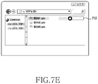
- FIG. 7A to FIG. 7H are example diagrams executing a file by using sight-line information of an electronic device according to an embodiment of the disclosure.
- the electronic device may execute a stored file by using sight-line information.
- the electronic device may output an explorer 710 displaying a list of at least one file stored in a memory (e.g., the memory 130 of FIG. 1 or the memory 220 of FIG. 2 ) at one side of a display (e.g., the display device 160 of FIG. 1 or the display 230 of FIG. 2 ).
- the electronic device may recognize a sight-line movement through a sight-line tracking module (e.g., the sight-line tracking module 240 of FIG. 2 ). As shown in FIG. 7B , in response to it being identified that a user's sight-line 71 faces a specified file 711 , the electronic device may highlight the specified file 711 .
- a sight-line tracking module e.g., the sight-line tracking module 240 of FIG. 2 .
- the electronic device may identify that a user intends to execute the specified file 711 , and as shown in FIG. 7C , may display a notification UI 713 of feeding back that the specified file 711 is in an execution waiting state, on the right of the specified file 711 .
- the electronic device in response to the user's sight-line being moved to the notification UI 713 , may display a guide UI 712 .
- the guide UI 712 may guide a movement extent and movement path of the sight-line 71 for content execution, to the user.
- the electronic device may change a background color of the guide UI 712 according to a movement of the sight-line 71 , to feed back the movement extent of the sight-line 71 .
- the electronic device may display the movement extent of the sight-line 71 in a text form (e.g., xx %).
- the operation of FIG. 7E providing the guide UI 712 may be omitted.
- the electronic device may change a color of the guide UI 712 in response to the movement of the sight-line 71 .
- the electronic device may execute the specified file 711 , and output an execution screen on the display.
- FIG. 8A to FIG. 8F are example diagrams executing an image by using sight-line information of an electronic device according to an embodiment of the disclosure.
- the electronic device e.g., the electronic device 101 of FIG. 1 or the electronic device 200 of FIG. 2
- the electronic device may execute an image (e.g., a photo) by using sight-line information.
- the electronic device may output a list of images stored in a memory (e.g., the memory 130 of FIG. 1 or the memory 220 of FIG. 2 ) in a thumbnail form at one side (e.g., a lower end) of a display (e.g., the display device 160 of FIG. 1 or the display 230 of FIG. 2 ).
- a memory e.g., the memory 130 of FIG. 1 or the memory 220 of FIG. 2
- a thumbnail form at one side (e.g., a lower end) of a display (e.g., the display device 160 of FIG. 1 or the display 230 of FIG. 2 ).
- the electronic device may sense that the user's sight-line 81 has been moved to the specified image 811 through a sight-line tracking module (e.g., the sight-line tracking module 240 of FIG. 2 ). According to some embodiment, the electronic device may highlight the specified image 811 in order to feed back that the sight-line has been moved to the specified image 811 .
- a sight-line tracking module e.g., the sight-line tracking module 240 of FIG. 2
- the electronic device may highlight the specified image 811 in order to feed back that the sight-line has been moved to the specified image 811 .
- the electronic device may identify that the user intends to execute the specified image 811 , and thus display a dynamic UI 813 .
- the electronic device may provide, as the dynamic UI 813 , an image which is semitransparent (e.g., a transparency of 50%) and gets bigger than the specified image 811 by a set size (or rate).
- the electronic device may feed back, to the user, that the specified image 811 is in a state of being executable through a sight-line movement (i.e., an execution waiting state).
- the electronic device may vary the dynamic UI 813 in response to the movement of the sight-line 81 .
- the electronic device may increase a size of the dynamic UI 813 in response to the sight-line movement.
- the electronic device may sequentially decrease a transparency of the dynamic UI 813 in response to the sight-line movement.
- the electronic device may display reference information (e.g., a reference UI) for identifying that an input of an execution command of the specified image 811 is completed.
- reference UI may be displayed in a dotted-line square box form which has a size of a specific rate (e.g., 70%) of an execution screen of the specified image 811 .
- a specific rate e.g. 70%
- the electronic device may execute the specified image 811 .
- the electronic device may visually feed back that the execution has been completed.
- the electronic device may display a mark 815 around the executed image 811 .
- the electronic device may provide a feedback on the execution completion in various schemes (e.g., sight, hearing and/or touch).
- FIG. 9A to FIG. 9C are example diagrams executing an application by using sight-line direction information of an electronic device according to an embodiment of the disclosure.
- the electronic device e.g., the electronic device of FIG. 1 or the electronic device 200 of FIG. 2
- the electronic device may execute a specified function according to a direction of a sight-line.
- the electronic device may display an icon 911 capable of executing an application, at one side of a display (e.g., the display device 160 of FIG. 1 or the display 230 of FIG. 2 ).
- the figure of reference numeral 910 illustrates only one icon for description convenience's sake, but an embodiment of the disclosure is not limited to this.
- the electronic device may display a home screen (or menu screen) that includes a plurality of icons.
- the electronic device may display a first dynamic UI 913 a and a second dynamic UI 913 b related with the icon 911 , around the icon 911 .
- the first dynamic UI 913 a may be related with a first function of an application.
- the first dynamic UI 913 a may be a thumbnail form of an execution screen (e.g., a chat window) of the first function.
- the second dynamic UI 913 b may be related with a second function (e.g., notification stop) of the application.
- the figure of reference numeral 930 illustrates two dynamic UIs for description convenience's sake, but an embodiment of the disclosure is not limited to this.
- the electronic device may display three or more dynamic UIs around the icon 911 .
- the electronic device in response to the sight-line 91 being moved to the first dynamic UI 913 a , as shown in figures of reference numerals 940 to 960 , the electronic device may vary the first dynamic UI 913 a in response to the movement of the sight-line 91 .
- the electronic device may increase a size of the first dynamic UI 913 a in response to the movement of the sight-line 91 .
- the figures of reference numerals 940 to 960 illustrate that a transparency of the first dynamic UI 913 a is “0”, but the first dynamic UI 913 a may be displayed semi-transparently (e.g., a transparency of 50%) until before the first function is executed.
- the transparency of the first dynamic UI 913 a may be gradually decreased in response to the movement of the sight-line 91 .
- the transparency of the first dynamic UI 913 a may be gradually decreased from 50% to 0%.
- the electronic device may execute the first function.
- the electronic device may display a chat screen as a full screen.
- the electronic device may not display the second dynamic UI 913 b.
- the electronic device in response to the sight-line 91 being moved to the second dynamic UI 913 b , as shown in figures of reference numerals 970 to 990 , the electronic device according to an embodiment of the disclosure may display a guide UI 912 , and move the second dynamic UI 913 b along the guide UI 912 in response to the movement of the sight-line 91 . According to some embodiment, the electronic device may change a color of the guide UI 912 in response to the movement of the second dynamic UI 913 b.
- the electronic device may execute the second function. For example, as shown in the figure of reference numeral 990 , by performing a notification ending function, the electronic device may eliminate an indicator 92 of notifying the existence of an unidentified message from the icon 911 .
- the electronic device may not display the first dynamic UI 913 a.
- FIG. 10A to FIG. 10G are example diagrams executing content by using sight-line information in a three-dimensional space according to an embodiment of the disclosure.
- the electronic device may execute content by using sight-line information in a three-dimensional space.
- the electronic device may be a virtual reality (VR) device.
- VR virtual reality
- the electronic device may provide a three-dimensional screen.
- the three-dimensional screen may display at least one virtual object in a living room space of real world that is recognized by means of the VR device.
- the electronic device may display a ball 1011 at one side (e.g., the air) of the three-dimensional space, and display a web browser 1015 on a table.
- the electronic device in response to a user's sight-line 11 being moved to the ball 1011 , may move the virtual ball 1011 in a set direction (e.g., a left and lower direction). This is merely an example, and the virtual ball may be moved in various directions.
- the electronic device may move the virtual ball 1011 in a table direction in response to the movement of the sight-line 11 .
- the electronic device may execute content. For example, as shown in FIG. 10F , the electronic device may change the web browser 1015 of the table into a football game screen 1017 and output the football game screen 1017 on the table.
- the electronic device may move the ball 1011 to the original position.
- the electronic device may separately provide a semitransparent ball, and move the semitransparent ball in response to a sight-line movement. In this case, the operation of FIG. 10G may be omitted.
- the electronic device may provide an auditory feedback and/or a tactile feedback, together with a visual feedback.
- the electronic device may provide the auditory feedback and/or the tactile feedback.
- the electronic device may gradually increase an effect sound or gradually increase a vibration intensity according to a sight-line movement until the command of execution of the content dependent on the sight-line movement is completed.
- the electronic device may shorten an output cycle of an effect sound or vibration according to the sight-line movement until the command of execution of the content dependent on the sight-line movement is completed.
- the electronic device may select content through various pointing devices (e.g., a mouse, a touch, a hover, a gesture, etc.), and move the pointing devices according to a set condition, to execute the content, and feed back in a visual, auditory or tactile manner that a command of execution of the selected content is being inputted in response to the movement of the pointing devices.
- various pointing devices e.g., a mouse, a touch, a hover, a gesture, etc.
- Various embodiments of the disclosure may efficiently control the execution of content by using sight-line information. For example, in various embodiments of the disclosure, a user may move a sight-line fast or slowly, to control an execution speed of content. Also, various embodiments of the disclosure do not immediately cancel a command of execution of content even though the sight-line deviates temporarily and thus, may prevent an inconvenience in which, regardless of a user's intention, the content execution is canceled in response to the sight-line temporarily deviating.
- various embodiments of the disclosure may execute content by using only sight-line information and thus, do not require a separate input device. Also, various embodiments of the disclosure execute the content by a movement of a sight-line and thus, may solve a conventional inconvenience in which the content is executed in response to simply staring at the content without an intention to execute the content. Also, various embodiments of the disclosure may perform another function according to a movement direction of the sight-line and thus, may easily execute various functions related with content.
- the electronic device may be one of various types of electronic devices.
- the electronic devices may include, for example, at least one of a portable communication device (e.g., a smart phone), a computer device, a portable multimedia device, a portable medical device, a camera, a wearable device, or a home appliance.
- a portable communication device e.g., a smart phone
- a computer device e.g., a laptop, a tablet, or a portable multimedia device
- portable medical device e.g., a portable medical device
- camera e.g., a camera
- a wearable device e.g., a smart watch
- a home appliance e.g.
- such terms as “1st,” “2nd,” “first” or “second” may modify corresponding components regardless of an importance or an order, be used to distinguish a component from another, and does not limit the corresponding components. It is to be understood that if an element (e.g., a first element) is referred to, “(operatively or communicatively) connected with,” or “connected to” another element (e.g., a second element), it means that the element may be coupled with the other element directly, or via other element (e.g., a third element).
- module includes a unit implemented in hardware, software, or firmware, and may interchangeably be used with other terms, for example, “logic,” “logic block,” “part,” or “circuitry”.
- a module may be a single integral component, or a minimum unit or part thereof, adapted to perform one or more functions.
- the module may be implemented in a form of an application-specific integrated circuit (ASIC).
- ASIC application-specific integrated circuit
- Various embodiments as set forth herein may be implemented as software (e.g., the program 140 ) including instructions that are stored in a machine readable storage medium (e.g., internal memory 136 or external memory 138 ) that is readable by a machine (e.g., computer).
- the machine may invoke instructions stored in the storage medium, be operated to perform functions according to the instructions invoked, and include the electronic device (e.g., the electronic device 101 , the electronic device 200 ) according to embodiments disclosed.
- the instructions are executed by a processor (e.g., the processor 120 , the processor 210 ), the processor may execute functions corresponding to the instructions directly or using other components under the control of the processor.
- the instructions may include a code generated or executed by a compiler or an interpreter.
- the machine-readable storage medium may be provided in the form of a non-transitory storage medium.
- non-transitory simply means that the storage medium does not include a signal and is tangible, but does not differentiate between semi-permanently storing the data in the storage medium and temporarily storing the data in the storage medium.
- a method may be included and provided in a computer program product.
- the computer program product may be traded as a product between a seller and a buyer.
- the computer program product may be distributed in the form of a machine-readable storage medium (e.g., compact disc read only memory (CD-ROM)), or be distributed online via an application store (e.g., Play StoreTM). If distributed online, at least part of the computer program product may be temporarily generated or at least temporarily stored in the storage medium, such as memory of the manufacturer's server, a server of the application store, or a relay server.
- a machine-readable storage medium e.g., compact disc read only memory (CD-ROM)
- an application store e.g., Play StoreTM
- each component may include a single entity or multiple entities, and part of the above-described components may be omitted, or other components may be added.
- the part of components e.g., modules or programs
- operations performed by the module, the program, or another component may be carried out sequentially, in parallel, repeatedly, or heuristically, or at least part operation may be executed in a different order or omitted, or other operations may be added.
Landscapes
- Engineering & Computer Science (AREA)
- General Engineering & Computer Science (AREA)
- Theoretical Computer Science (AREA)
- Human Computer Interaction (AREA)
- Physics & Mathematics (AREA)
- General Physics & Mathematics (AREA)
- Multimedia (AREA)
- Signal Processing (AREA)
- Health & Medical Sciences (AREA)
- General Health & Medical Sciences (AREA)
- Social Psychology (AREA)
- Computer Networks & Wireless Communication (AREA)
- Databases & Information Systems (AREA)
- Life Sciences & Earth Sciences (AREA)
- Chemical & Material Sciences (AREA)
- Analytical Chemistry (AREA)
- Biomedical Technology (AREA)
- Biophysics (AREA)
- Neurosurgery (AREA)
- User Interface Of Digital Computer (AREA)
Abstract
Description
Claims (18)
Applications Claiming Priority (3)
| Application Number | Priority Date | Filing Date | Title |
|---|---|---|---|
| KR1020170127918A KR102518404B1 (en) | 2017-09-29 | 2017-09-29 | Electronic device and method for executing content using sight-line information thereof |
| KR10-2017-0127918 | 2017-09-29 | ||
| PCT/KR2018/010735 WO2019066323A1 (en) | 2017-09-29 | 2018-09-13 | Electronic device and content executing method using sight-line information thereof |
Publications (2)
| Publication Number | Publication Date |
|---|---|
| US20200249750A1 US20200249750A1 (en) | 2020-08-06 |
| US11334152B2 true US11334152B2 (en) | 2022-05-17 |
Family
ID=65902344
Family Applications (1)
| Application Number | Title | Priority Date | Filing Date |
|---|---|---|---|
| US16/652,089 Active US11334152B2 (en) | 2017-09-29 | 2018-09-13 | Electronic device and content executing method using sight-line information thereof |
Country Status (3)
| Country | Link |
|---|---|
| US (1) | US11334152B2 (en) |
| KR (1) | KR102518404B1 (en) |
| WO (1) | WO2019066323A1 (en) |
Families Citing this family (7)
| Publication number | Priority date | Publication date | Assignee | Title |
|---|---|---|---|---|
| US12511037B1 (en) * | 2020-10-26 | 2025-12-30 | Apple Inc. | Method and device for typing visualization |
| US11762458B2 (en) * | 2021-02-15 | 2023-09-19 | Sony Group Corporation | Media display device control based on eye gaze |
| JPWO2022230165A1 (en) * | 2021-04-30 | 2022-11-03 | ||
| US11592899B1 (en) * | 2021-10-28 | 2023-02-28 | Tectus Corporation | Button activation within an eye-controlled user interface |
| WO2023113204A1 (en) * | 2021-12-13 | 2023-06-22 | 삼성전자 주식회사 | Method for executing and cancelling function by using flexible ui and user response in process of automatically executing function, and device thereof |
| US12008160B2 (en) | 2022-03-30 | 2024-06-11 | Apple Inc. | Eye tracking based selection of a user interface (UI) element based on targeting criteria |
| US12282595B2 (en) * | 2023-03-30 | 2025-04-22 | Motorola Mobility Llc | Managing notifications among connected devices |
Citations (13)
| Publication number | Priority date | Publication date | Assignee | Title |
|---|---|---|---|---|
| US20100182232A1 (en) | 2009-01-22 | 2010-07-22 | Alcatel-Lucent Usa Inc. | Electronic Data Input System |
| US8235529B1 (en) | 2011-11-30 | 2012-08-07 | Google Inc. | Unlocking a screen using eye tracking information |
| US20130145304A1 (en) | 2011-12-02 | 2013-06-06 | International Business Machines Corporation | Confirming input intent using eye tracking |
| US20130321265A1 (en) | 2011-02-09 | 2013-12-05 | Primesense Ltd. | Gaze-Based Display Control |
| US20140372957A1 (en) | 2013-06-18 | 2014-12-18 | Brian E. Keane | Multi-step virtual object selection |
| WO2014210151A1 (en) | 2013-06-28 | 2014-12-31 | Microsoft Corporation | Web-like hierarchical menu display configuration for a near-eye display |
| US20150205494A1 (en) | 2014-01-23 | 2015-07-23 | Jason Scott | Gaze swipe selection |
| US20150227194A1 (en) * | 2012-10-25 | 2015-08-13 | Kyocera Corporation | Mobile terminal device and input operation receiving method |
| US20150268821A1 (en) | 2014-03-20 | 2015-09-24 | Scott Ramsby | Selection using eye gaze evaluation over time |
| US20160077337A1 (en) * | 2014-09-15 | 2016-03-17 | Google Inc. | Managing Information Display |
| US20160195924A1 (en) | 2013-08-27 | 2016-07-07 | Auckland Uniservices Limited | Gaze-controlled interface method and system |
| US20160231810A1 (en) * | 2013-09-02 | 2016-08-11 | Sony Corporation | Information processing apparatus, information processing method, and program |
| US20170185146A1 (en) * | 2015-12-29 | 2017-06-29 | Ford Global Technologies, Llc | Vehicle notification system including transparent and mirrored displays |
Family Cites Families (3)
| Publication number | Priority date | Publication date | Assignee | Title |
|---|---|---|---|---|
| KR20140073730A (en) * | 2012-12-06 | 2014-06-17 | 엘지전자 주식회사 | Mobile terminal and method for controlling mobile terminal |
| KR20160033376A (en) * | 2014-09-18 | 2016-03-28 | (주)에프엑스기어 | Head-mounted display controlled by line of sight, method for controlling the same and computer program for controlling the same |
| KR101671838B1 (en) * | 2015-06-17 | 2016-11-03 | 주식회사 비주얼캠프 | Input device using eye-tracking |
-
2017
- 2017-09-29 KR KR1020170127918A patent/KR102518404B1/en active Active
-
2018
- 2018-09-13 WO PCT/KR2018/010735 patent/WO2019066323A1/en not_active Ceased
- 2018-09-13 US US16/652,089 patent/US11334152B2/en active Active
Patent Citations (15)
| Publication number | Priority date | Publication date | Assignee | Title |
|---|---|---|---|---|
| US20100182232A1 (en) | 2009-01-22 | 2010-07-22 | Alcatel-Lucent Usa Inc. | Electronic Data Input System |
| US20130321265A1 (en) | 2011-02-09 | 2013-12-05 | Primesense Ltd. | Gaze-Based Display Control |
| US8235529B1 (en) | 2011-11-30 | 2012-08-07 | Google Inc. | Unlocking a screen using eye tracking information |
| US20130145304A1 (en) | 2011-12-02 | 2013-06-06 | International Business Machines Corporation | Confirming input intent using eye tracking |
| US20150227194A1 (en) * | 2012-10-25 | 2015-08-13 | Kyocera Corporation | Mobile terminal device and input operation receiving method |
| KR20160020571A (en) | 2013-06-18 | 2016-02-23 | 마이크로소프트 테크놀로지 라이센싱, 엘엘씨 | Multi-step virtual object selection |
| US20140372957A1 (en) | 2013-06-18 | 2014-12-18 | Brian E. Keane | Multi-step virtual object selection |
| WO2014210151A1 (en) | 2013-06-28 | 2014-12-31 | Microsoft Corporation | Web-like hierarchical menu display configuration for a near-eye display |
| US20160195924A1 (en) | 2013-08-27 | 2016-07-07 | Auckland Uniservices Limited | Gaze-controlled interface method and system |
| US20160231810A1 (en) * | 2013-09-02 | 2016-08-11 | Sony Corporation | Information processing apparatus, information processing method, and program |
| US20150205494A1 (en) | 2014-01-23 | 2015-07-23 | Jason Scott | Gaze swipe selection |
| KR20160113139A (en) | 2014-01-23 | 2016-09-28 | 마이크로소프트 테크놀로지 라이센싱, 엘엘씨 | Gaze swipe selection |
| US20150268821A1 (en) | 2014-03-20 | 2015-09-24 | Scott Ramsby | Selection using eye gaze evaluation over time |
| US20160077337A1 (en) * | 2014-09-15 | 2016-03-17 | Google Inc. | Managing Information Display |
| US20170185146A1 (en) * | 2015-12-29 | 2017-06-29 | Ford Global Technologies, Llc | Vehicle notification system including transparent and mirrored displays |
Also Published As
| Publication number | Publication date |
|---|---|
| KR20190038003A (en) | 2019-04-08 |
| KR102518404B1 (en) | 2023-04-06 |
| WO2019066323A1 (en) | 2019-04-04 |
| US20200249750A1 (en) | 2020-08-06 |
Similar Documents
| Publication | Publication Date | Title |
|---|---|---|
| US11538443B2 (en) | Electronic device for providing augmented reality user interface and operating method thereof | |
| US11487558B2 (en) | Electronic device and screen sharing method using same | |
| US11334152B2 (en) | Electronic device and content executing method using sight-line information thereof | |
| US11366584B2 (en) | Method for providing function or content associated with application, and electronic device for carrying out same | |
| US10929002B2 (en) | Electronic device for controlling a plurality of applications | |
| US11353968B2 (en) | Electronic device and control method for providing display coordinates on an external display device | |
| US20230019876A1 (en) | Electronic device comprising a plurality of touch screen displays and screen division method | |
| KR102734793B1 (en) | Electronic device for displaying message and operating method thereof | |
| US11294452B2 (en) | Electronic device and method for providing content based on the motion of the user | |
| EP3705982B1 (en) | Apparatus and method for adaptively configuring user interface | |
| US12537892B2 (en) | Electronic device including flexible display, and operating method thereof | |
| US20210127000A1 (en) | Electronic device and method for controlling display operation thereof | |
| US11216154B2 (en) | Electronic device and method for executing function according to stroke input | |
| US20210174766A1 (en) | Electronic device for controlling divided screen | |
| AU2018321518B2 (en) | Method for determining input detection region corresponding to user interface and electronic device thereof | |
| KR102436435B1 (en) | Electronic device for executing various functions based on a signal recevied from an electric pen | |
| US11550456B2 (en) | Method for mapping function of application and electronic device therefor | |
| US11221761B2 (en) | Electronic device for controlling operation by using display comprising restriction area, and operation method therefor | |
| US11622097B2 (en) | Apparatus and method for providing point of interest (POI) information in 360 video | |
| KR20210121923A (en) | Methods for control a background application and an electronic device supporting the same | |
| US12014102B2 (en) | Foldable electronic device for displaying user interface and method therefor | |
| US12406406B2 (en) | Electronic device for providing augmented reality mode, and operating method therefor |
Legal Events
| Date | Code | Title | Description |
|---|---|---|---|
| AS | Assignment |
Owner name: SAMSUNG ELECTRONICS CO., LTD., KOREA, REPUBLIC OF Free format text: ASSIGNMENT OF ASSIGNORS INTEREST;ASSIGNORS:CHOI, SEUNG HWAN;KIM, HYUNJIN;PARK, DA-HYE;AND OTHERS;SIGNING DATES FROM 20200301 TO 20200319;REEL/FRAME:052255/0681 |
|
| FEPP | Fee payment procedure |
Free format text: ENTITY STATUS SET TO UNDISCOUNTED (ORIGINAL EVENT CODE: BIG.); ENTITY STATUS OF PATENT OWNER: LARGE ENTITY |
|
| STPP | Information on status: patent application and granting procedure in general |
Free format text: NON FINAL ACTION MAILED |
|
| STPP | Information on status: patent application and granting procedure in general |
Free format text: RESPONSE TO NON-FINAL OFFICE ACTION ENTERED AND FORWARDED TO EXAMINER |
|
| STPP | Information on status: patent application and granting procedure in general |
Free format text: FINAL REJECTION MAILED |
|
| STPP | Information on status: patent application and granting procedure in general |
Free format text: RESPONSE AFTER FINAL ACTION FORWARDED TO EXAMINER |
|
| STPP | Information on status: patent application and granting procedure in general |
Free format text: NOTICE OF ALLOWANCE MAILED -- APPLICATION RECEIVED IN OFFICE OF PUBLICATIONS |
|
| STPP | Information on status: patent application and granting procedure in general |
Free format text: PUBLICATIONS -- ISSUE FEE PAYMENT VERIFIED |
|
| STCF | Information on status: patent grant |
Free format text: PATENTED CASE |
|
| MAFP | Maintenance fee payment |
Free format text: PAYMENT OF MAINTENANCE FEE, 4TH YEAR, LARGE ENTITY (ORIGINAL EVENT CODE: M1551); ENTITY STATUS OF PATENT OWNER: LARGE ENTITY Year of fee payment: 4 |