US11326918B2 - Flowmeter - Google Patents

Flowmeter Download PDF

Info

Publication number
US11326918B2
US11326918B2 US17/173,642 US202117173642A US11326918B2 US 11326918 B2 US11326918 B2 US 11326918B2 US 202117173642 A US202117173642 A US 202117173642A US 11326918 B2 US11326918 B2 US 11326918B2
Authority
US
United States
Prior art keywords
passage
flowmeter
opening
end opening
flow rate
Prior art date
Legal status (The legal status is an assumption and is not a legal conclusion. Google has not performed a legal analysis and makes no representation as to the accuracy of the status listed.)
Active
Application number
US17/173,642
Other versions
US20210164819A1 (en
Inventor
Kazuaki Ueda
Yuusuke Yoshida
Kengo Ito
Current Assignee (The listed assignees may be inaccurate. Google has not performed a legal analysis and makes no representation or warranty as to the accuracy of the list.)
Denso Corp
Original Assignee
Denso Corp
Priority date (The priority date is an assumption and is not a legal conclusion. Google has not performed a legal analysis and makes no representation as to the accuracy of the date listed.)
Filing date
Publication date
Application filed by Denso Corp filed Critical Denso Corp
Assigned to DENSO CORPORATION reassignment DENSO CORPORATION ASSIGNMENT OF ASSIGNORS INTEREST (SEE DOCUMENT FOR DETAILS). Assignors: ITO, KENGO, YOSHIDA, YUUSUKE, UEDA, KAZUAKI
Publication of US20210164819A1 publication Critical patent/US20210164819A1/en
Application granted granted Critical
Publication of US11326918B2 publication Critical patent/US11326918B2/en
Active legal-status Critical Current
Anticipated expiration legal-status Critical

Links

Images

Classifications

    • GPHYSICS
    • G01MEASURING; TESTING
    • G01FMEASURING VOLUME, VOLUME FLOW, MASS FLOW OR LIQUID LEVEL; METERING BY VOLUME
    • G01F1/00Measuring the volume flow or mass flow of fluid or fluent solid material wherein the fluid passes through a meter in a continuous flow
    • G01F1/68Measuring the volume flow or mass flow of fluid or fluent solid material wherein the fluid passes through a meter in a continuous flow by using thermal effects
    • G01F1/684Structural arrangements; Mounting of elements, e.g. in relation to fluid flow
    • G01F1/6842Structural arrangements; Mounting of elements, e.g. in relation to fluid flow with means for influencing the fluid flow
    • FMECHANICAL ENGINEERING; LIGHTING; HEATING; WEAPONS; BLASTING
    • F02COMBUSTION ENGINES; HOT-GAS OR COMBUSTION-PRODUCT ENGINE PLANTS
    • F02DCONTROLLING COMBUSTION ENGINES
    • F02D41/00Electrical control of supply of combustible mixture or its constituents
    • F02D41/02Circuit arrangements for generating control signals
    • F02D41/18Circuit arrangements for generating control signals by measuring intake air flow
    • FMECHANICAL ENGINEERING; LIGHTING; HEATING; WEAPONS; BLASTING
    • F02COMBUSTION ENGINES; HOT-GAS OR COMBUSTION-PRODUCT ENGINE PLANTS
    • F02MSUPPLYING COMBUSTION ENGINES IN GENERAL WITH COMBUSTIBLE MIXTURES OR CONSTITUENTS THEREOF
    • F02M35/00Combustion-air cleaners, air intakes, intake silencers, or induction systems specially adapted for, or arranged on, internal-combustion engines
    • F02M35/10Air intakes; Induction systems
    • F02M35/10373Sensors for intake systems
    • F02M35/10386Sensors for intake systems for flow rate
    • GPHYSICS
    • G01MEASURING; TESTING
    • G01FMEASURING VOLUME, VOLUME FLOW, MASS FLOW OR LIQUID LEVEL; METERING BY VOLUME
    • G01F1/00Measuring the volume flow or mass flow of fluid or fluent solid material wherein the fluid passes through a meter in a continuous flow
    • G01F1/68Measuring the volume flow or mass flow of fluid or fluent solid material wherein the fluid passes through a meter in a continuous flow by using thermal effects
    • G01F1/684Structural arrangements; Mounting of elements, e.g. in relation to fluid flow
    • G01F1/6847Structural arrangements; Mounting of elements, e.g. in relation to fluid flow where sensing or heating elements are not disturbing the fluid flow, e.g. elements mounted outside the flow duct
    • GPHYSICS
    • G01MEASURING; TESTING
    • G01FMEASURING VOLUME, VOLUME FLOW, MASS FLOW OR LIQUID LEVEL; METERING BY VOLUME
    • G01F1/00Measuring the volume flow or mass flow of fluid or fluent solid material wherein the fluid passes through a meter in a continuous flow
    • G01F1/72Devices for measuring pulsing fluid flows
    • GPHYSICS
    • G01MEASURING; TESTING
    • G01FMEASURING VOLUME, VOLUME FLOW, MASS FLOW OR LIQUID LEVEL; METERING BY VOLUME
    • G01F5/00Measuring a proportion of the volume flow

Definitions

  • the present disclosure relates to a flowmeter.
  • a flowmeter is disposed in a main passage and includes a flow rate detector configured to detect a flow rate of a fluid flowing through the flowmeter from the main passage.
  • Some flowmeters that cannot distinguish a flow direction of the fluid in detecting the flow rate include a member configured to reduce a dynamic pressure, which is generated when the fluid flows in a backward direction, around an outlet of a detecting passage.
  • a flowmeter is disposed in a passage through which a fluid flows.
  • the flowmeter includes a first passage and a second passage.
  • the first passage defines an opening through which a part of the fluid flows into the first passage.
  • the second passage branches off from the first passage and includes a flow rate detector configured to detect a flow rate of the fluid flowing through the second passage from the first passage.
  • the second passage has one end at which the second passage branches off from the first passage and the other end opposite to the one end.
  • the second passage includes at least one end opening at the other end of the second passage and an inflow reducer configured to restrict the fluid from flowing into the second passage through the at least one end opening.
  • FIG. 1 is a cross-sectional view of a flowmeter of a first embodiment.
  • FIG. 2 is a side view of the flowmeter viewed in a ⁇ X direction.
  • FIG. 3 is a cross-sectional view of the flowmeter of the first embodiment.
  • FIG. 4 is a cross-sectional view of the flowmeter of the first embodiment.
  • FIG. 5 is a cross-sectional view of a flowmeter of a comparative example.
  • FIG. 6 is a cross-sectional view of the flowmeter of the comparative example.
  • FIG. 7 is a cross-sectional view of a flowmeter of a second embodiment.
  • FIG. 8 is a cross-sectional view of the flowmeter of the second embodiment.
  • FIG. 9 is a cross-sectional view of a flowmeter of a comparative example.
  • FIG. 10 is a cross-sectional view of a flowmeter of a third embodiment.
  • FIG. 11 is a cross-sectional view of the flowmeter of the third embodiment.
  • FIG. 12 is a cross-sectional view of a flowmeter of a fourth embodiment.
  • FIG. 13 is a cross-sectional view of the flowmeter of the fourth embodiment.
  • FIG. 14 is a cross-sectional view of a flowmeter of a fifth embodiment.
  • FIG. 15 is a cross-sectional view of the flowmeter of the fifth embodiment.
  • FIG. 16 is a cross-sectional view of a flowmeter of a sixth embodiment.
  • FIG. 17 is a cross-sectional view of a flowmeter of a seventh embodiment.
  • FIG. 18 is a cross-sectional view of a flowmeter of an eighth embodiment.
  • FIG. 19 is a cross-sectional view of a flowmeter of a ninth embodiment.
  • FIG. 20 is a cross-sectional view of a flowmeter of a tenth embodiment.
  • FIG. 21 is a cross-sectional view of a flowmeter of an eleventh embodiment.
  • FIG. 22 is a cross-sectional view of a flowmeter of a twelfth embodiment.
  • FIG. 23 is a cross-sectional view of a flowmeter of a thirteenth embodiment.
  • FIG. 24 is a cross-sectional view of a flowmeter of a fourteenth embodiment.
  • FIG. 25 is a cross-sectional view of a flowmeter of a fifteenth embodiment.
  • FIG. 26 is a cross-sectional view of a flowmeter of a sixteenth embodiment.
  • FIG. 27 is a cross-sectional view of a flowmeter of a seventeenth embodiment.
  • FIG. 28 is a cross-sectional view of a flowmeter of an eighteenth embodiment.
  • FIG. 29 is a cross-sectional view of a flowmeter of a nineteenth embodiment.
  • FIG. 30 is a cross-sectional view of a flowmeter of a twentieth embodiment.
  • FIG. 31 is a cross-sectional view of a flowmeter of a twenty-first embodiment.
  • FIG. 32 is a cross-sectional view of a flowmeter of a twenty-second embodiment.
  • FIG. 33 is a cross-sectional view of a flowmeter of a twenty-third embodiment.
  • FIG. 34 is a cross-sectional view of a flowmeter of a twenty-fourth embodiment.
  • FIG. 35 is a cross-sectional view of a flowmeter of a twenty-fifth embodiment.
  • FIG. 36 is a cross-sectional view of a flowmeter of a twenty-sixth embodiment.
  • FIG. 37 is a cross-sectional view of a flowmeter of a twenty-seventh embodiment.
  • FIG. 38 is a cross-sectional view of a flowmeter of a twenty-eighth embodiment.
  • FIG. 39 is a cross-sectional view of a flowmeter of a twenty-ninth embodiment.
  • a flowmeter is disposed in a main passage and includes a flow rate detector configured to detect a flow rate of a fluid flowing through the flowmeter from the main passage.
  • Some flowmeters that cannot distinguish a flow direction of the fluid in detecting the flow rate include a member configured to reduce a dynamic pressure, which is generated when the fluid flows in a backward direction, around an outlet of a detecting passage. As a result, the fluid is restricted from flowing into the flowmeter in the backward direction and a measurement error of the flow rate detector can be reduced.
  • a flowmeter is provided.
  • the flowmeter is disposed in a passage through which a fluid flows.
  • the flowmeter includes a first passage and a second passage.
  • the first passage defines an opening through which a part of the fluid flows into the first passage.
  • the second passage branches off from the first passage and includes a flow rate detector configured to detect a flow rate of the fluid flowing through the second passage from the first passage.
  • the second passage has one end at which the second passage branches off from the first passage and the other end opposite to the one end.
  • the second passage includes at least one end opening at the other end of the second passage and an inflow reducer configured to restrict the fluid from flowing into the second passage through the at least one end opening.
  • a vortex is likely to generate in the at least one end opening, so that the fluid is restricted from flowing into the flowmeter due to the backward flow.
  • the measurement error of the flowmeter can be reduced by restricting the fluid from flowing into the flowmeter due to the backward flow.
  • a flowmeter 10 of a first embodiment as shown in FIG. 1 is disposed in a passage through which a fluid flows and configured to measure a flow rate of the fluid flowing through the passage.
  • the flowmeter 10 is inserted into an intake pipe IP that guides a gas to flow into a cylinder of an internal combustion engine.
  • a X axis, a Y axis, and a Z axis in FIG. 1 are three spatial axes that are perpendicular to each other.
  • the XYZ axes in FIG. 1 correspond to XYZ axes in other figures.
  • FIG. 1 is a cross-sectional view of the flowmeter 10 taken along a YZ plane. Regarding a flow direction of the fluid in FIG.
  • +Y direction is a forward direction and ⁇ Y direction is a backward direction.
  • the direction in which the fluid flows forward is shown as a direction FD.
  • the cylinder of the internal combustion engine is disposed on a +Y side of the flowmeter 10 .
  • the flowmeter 10 includes a first passage 100 , a second passage 200 , and a flow rate detector 300 .
  • the first passage 100 is a passage into which a part of the fluid flowing through the intake pipe IP flows.
  • the first passage 100 defines a first opening 110 on a ⁇ Y side of the first passage 100 and a second opening 120 on a +Y side of the first passage 100 .
  • the first passage 100 extends from the first opening 110 to the second opening 120 .
  • the second passage 200 branches off from the first passage 100 .
  • the second passage 200 branches off from the first passage 100 and extends to an end opening 220 .
  • FIG. 2 is a side view of the flowmeter 10 viewed in a ⁇ X direction.
  • the end opening 220 opens from the second passage 200 in the ⁇ X direction.
  • the flow rate detector 300 is disposed on +Z side of the second passage 200 .
  • the flow rate detector 300 is configured to detect a flow rate of the fluid flowing through the second passage 200 from the first passage 100 .
  • the flow rate detector 300 and its peripheral configurations are disposed on a far side (i.e., a +X side) of a surface of paper in FIG. 1 , thus they are shown in dashed lines.
  • a type of the flow rate detector 300 is a hot wire type.
  • the flow rate detector 300 may be a flap type or Karman vortex type flow rate detector.
  • FIG. 3 is a cross-sectional view of the flowmeter 10 taken along a XZ plane passing through the end opening 220 .
  • FIG. 3 is the cross-sectional view of the flowmeter 10 viewed in a direction of arrows III.
  • the flowmeter 10 includes a throttle portion 340 facing the flow rate detector 300 in the X direction.
  • the throttle portion 340 restricts a flow of the fluid passing through the flow rate detector 300 .
  • the flow rate detector 300 and the throttle portion 340 are located on a far side (i.e., +Y side) of a surface of paper in FIG. 3 , thus the flow rate detector 300 and the throttle portion 340 are shown in dashed lines.
  • the flowmeter 10 includes a protrusion 230 protruding into the second passage 200 from a part of a wall surface of the second passage 200 between the flow rate detector 300 and the end opening 220 .
  • the protrusion 230 protrudes in the ⁇ X direction from a portion of the wall surface located on +X side of the second passage 200 .
  • the portion of the wall surface located on the +X side of the second passage 200 is a facing surface that faces the end opening 220 .
  • the protrusion 230 protrudes in the ⁇ X direction from a portion of the wall surface located on the +X side and a +Y side of the second passage 200 .
  • a cross-sectional shape of the protrusion 230 taken along the XZ plane is triangular.
  • FIG. 4 illustrates a region R 1 formed by projecting the end opening 220 in the X direction that is a direction along a center line (CL) of the end opening 220 .
  • the center line CL of the end opening 220 is a line passing through a center (i.e, a gravity center) of a cross-section of a part of the end opening 220 on a +X side of the end opening 220 and a center (i.e, a gravity center) of a cross-section of a part of the end opening 220 on a ⁇ X side of the end opening 220 .
  • the protrusion 230 does not overlap with the region R 1 of the wall surface defining the second passage 200 .
  • the protrusion 230 is formed into a shape such that a flow resistance of the fluid flowing from the flow rate detector 300 to the end opening 220 is less than a flow resistance of the fluid flowing from the end opening 220 to the flow rate detector 300 .
  • the flowmeter 10 is configured to detect a flow rate of the fluid flowing through the intake pipe IP in the +Y direction (i.e., a forward direction). That is, the flow rate detector 300 detects a flow rate of a part of the fluid having flown into the first passage 100 through the first opening 110 and flowing to the end opening 220 . Thus, if the fluid flows into the flowmeter 10 through the end opening 220 to the first passage 100 , a measurement error of the flow rate detector 300 may occur. As shown in FIG. 1 , the flowmeter 10 includes the protrusion 230 . Thus, even if the fluid flows into the flowmeter 10 through the end opening 220 , the fluid is reflected at the protrusion 230 and a vortex VTa is generated (see FIG. 3 ), which can restrict the fluid from flowing into the flowmeter 10 in the backward direction.
  • FIG. 5 is a cross-sectional view of the flowmeter 10 p taken along the XZ plane passing through the end opening 220 .
  • the flowmeter 10 p of the comparative example does not include the protrusion 230 .
  • the flowmeter 10 of the first embodiment includes the protrusion 230 .
  • the measurement error of the flow rate detector 300 can be reduced by restricting the fluid from flowing into the flowmeter 10 in the backward direction.
  • the protrusion 230 protrudes in the ⁇ X direction from a portion of the wall surface of the second passage 200 located on the +X side of the second passage 200 .
  • a passage axis of the second passage 200 can be greatly changed at the protrusion 230 and the protrusion 230 can easily block a flow of the fluid flowing into the flowmeter 10 through the end opening 220 . Therefore, the vortex VTa is likely to generate.
  • the protrusion 230 is disposed in a portion of the wall surface of the second passage 200 that does not overlap with the region R 1 . Therefore, compared to a case in which the protrusion 230 is located within the region R 1 , the protrusion 230 is likely to block the fluid flowing into the flowmeter 10 through the end opening 220 . Thus, the vortex VTa is likely to generate.
  • the protrusion 230 is formed into a shape such that a flow resistance of the fluid flowing from the flow rate detector 300 to the end opening 220 is less than a flow resistance of the fluid flowing from the end opening 220 to the flow rate detector 300 .
  • the protrusion 230 blocks the fluid flowing into the flowmeter 10 through the end opening 220 and the vortex VTa is likely generated while the fluid flows smoothly into the first passage 100 toward the end opening 220 .
  • a flowmeter 12 of a second embodiment differs from the flowmeter 10 of the first embodiment in that the flowmeter 12 does not include the protrusion 230 , the flowmeter 12 includes an end opening 220 a and an end opening 220 b in place of the end opening 220 , and the flowmeter 12 includes a partition 240 .
  • Other portions are similar to those of the first embodiment.
  • the same reference numerals as those in the first embodiment indicate the same configurations with the first embodiment and a reference is made to the preceding descriptions.
  • the end opening 220 a opens from the second passage 200 in the ⁇ X direction.
  • the end opening 220 b opens from the second passage 200 in the +X direction.
  • the end opening 220 a and the end opening 220 b are rectangular openings that have the same size.
  • the partition 240 separates the end opening 220 a from the end opening 220 b .
  • the end opening 220 b is invisible behind the partition 240 .
  • the end opening 220 a is also invisible behind the partition 240 .
  • the partition 240 includes a thin portion 242 and a thick portion 244 .
  • the thin portion 242 is a portion of the partition overlapping with the end opening 220 a and the end opening 220 b .
  • the thick portion 244 is a portion of the partition 240 between the flow rate detector 300 and the thin portion 242 .
  • the thin portion 242 is thinner than the thick portion 244 .
  • FIG. 8 is a view illustrating a portion facing the end opening 220 a and the end opening 220 b .
  • the portion facing the end opening 220 a and the end opening 220 b is a portion of the partition 240 located within a region R 2 .
  • the region R 2 is formed by projecting the end opening 220 a and the end opening 220 b in the X direction that is a center line direction of the end opening 220 a and the end opening 220 b.
  • the flowmeter 12 includes the partition 240 .
  • the partition 240 Even if the fluid flows into the flowmeter 12 through the end opening 220 a and the end opening 220 b , the fluid flowing along the thin portion 242 is reflected at the thick portion 244 of the partition 240 to generate a vortex VTb. As a result, the fluid is restricted from flowing into the flowmeter 10 in the backward direction.
  • a flowmeter 12 p of a comparative example differs from the flowmeter 12 of the second embodiment in that the flowmeter 12 p does not include the partition 240 .
  • Other configurations are similar to those of the second embodiment.
  • the same reference numerals as those in the second embodiment show the same configurations and references are made to the preceding descriptions.
  • the flowmeter 12 p of the comparative example does not include the partition 240 , the fluid flowing into the flowmeter 12 p through the end opening 220 a and the end opening 220 b flows toward the flow rate detector 300 as shown in a flow CF 2 . Such generation of the flow CF 2 leads to the measurement error of the flow rate detector 300 .
  • the flowmeter 12 of the second embodiment includes the partition 240 .
  • the fluid flowing along the thin portion 242 is reflected at the thick portion 244 of the partition 240 to generate the vortex VTb.
  • the fluid is restricted from flowing into the flowmeter 12 in the backward direction. Therefore, the measurement error of the flow rate detector 300 can be reduced by restricting the fluid from flowing into the flowmeter 12 in the backward direction.
  • a flowmeter 14 of a third embodiment differs from the flowmeter 12 of the second embodiment in that the flowmeter 14 does not include the partition 240 and includes an end opening 220 c and an end opening 220 d in place of the end opening 220 a and the end opening 220 b .
  • Other configurations are similar to those of the flowmeter 12 of the second embodiment.
  • the same reference numerals as those in the second embodiment indicate the same configurations with the second embodiment and references are made to the preceding descriptions.
  • the end opening 220 c opens from the second passage 200 in the ⁇ X direction.
  • the end opening 220 d opens from the second passage 200 in the +X direction.
  • a direction in which the end opening 220 c and the end opening 220 d face each other is defined as the X direction.
  • the end opening 220 c and the end opening 220 d have opening end surfaces.
  • the opening end surface of the end opening 220 c and the opening end surface of the end opening 220 d are tilted toward the same side relative to a facing line CD that connects between two centers of the end opening 220 c and the end opening 220 d .
  • both a line segment Lc showing the slope of the opening end surface of the end opening 220 c and a line segment Ld showing the slope of the opening end surface of the end opening 220 d have negative correlation between a component in the X axis and a component in a Z axis.
  • the line segment Lc and the line segment Ld extend from the +Z side to the ⁇ Z side as extending from the ⁇ X side to +X side, which means both the line segment Lc and the line segment Ld have negative correlation between the X direction and the Y direction. It is only required that the line segments have the same correlation.
  • the line segment Lc may have a slope that is different from a slope of the line segment Ld. That is, the line segment Lc and the line segment Ld are not necessarily parallel to each other.
  • the slope of the opening end surface of the end opening 220 c and the slope of the opening end surface of the end opening 220 d are not limited to have negative correlations between the X direction and the Z direction.
  • the slope of the opening end surface of the end opening 220 c and the slope of the opening end surface of the end opening 220 d may have positive correlations between the X direction and the Y direction.
  • FIG. 11 illustrates a state of the flowmeter 14 when the fluid flows into the flowmeter 14 through the end opening 220 c and the end opening 220 d .
  • the fluid flowing into the flowmeter 14 through the end opening 220 c and the fluid flowing into the flowmeter 14 through the end opening 220 d face each other to generate a shear stress.
  • the shear stress is likely to generate a vortex VTc.
  • the vortex VTc restricts the fluid from flowing into the flowmeter 14 through the end opening 220 c and the end opening 220 d , so that the measurement error of the flow rate detector 300 can be reduced.
  • a flowmeter 16 of a fourth embodiment differs from the flowmeter 14 of the third embodiment in that the flowmeter 16 includes a recess 260 .
  • Other configurations are similar to those of the third embodiment.
  • the same reference numerals with those in the third embodiment show the same configurations in the third embodiment and references are made to the preceding descriptions.
  • the recess 260 is entirely disposed within a range Rd of the wall surface of the second passage 200 .
  • the range Rd is formed by projecting the end opening 220 d onto the wall surface of the second passage 200 along the line segment Ld.
  • FIG. 13 illustrates a state of the flowmeter 16 where the fluid flows into the flowmeter 16 through the end opening 220 c and the end opening 220 d .
  • the fluid flowing into the flowmeter 16 through the end opening 220 c and the fluid flowing into the flowmeter 16 through the end opening 220 d face each other to generate a shear stress.
  • the shear stress is likely to generate a vortex VTd.
  • a flow of the fluid flowing into the flowmeter 16 through the end opening 220 d is reversed along the recess 260 , which assists to generate the vortex VTd.
  • a flowmeter 18 of a fifth embodiment differs from the flowmeter 16 of the fourth embodiment in that the flowmeter 18 includes a protrusion 280 in place of the recess 260 .
  • Other configurations are similar to those of the fourth embodiment.
  • the same reference numerals as those in the fourth embodiment show the same configurations with the fourth embodiment and references are made to the preceding descriptions.
  • the protrusion 280 protrudes from a portion of the wall surface of the second passage 200 into the second passage 200 .
  • the portion of the wall surface is entirely disposed within the region Rd.
  • FIG. 15 illustrates a state of the flowmeter 18 where the fluid flows into the flowmeter 18 through the end opening 220 c and the end opening 220 d .
  • the fluid flowing into the flowmeter 18 through the end opening 220 c and the fluid flowing into the flowmeter 18 through the end opening 220 d face each other to generate a shear stress.
  • the shear stress is likely to generate a vortex VTe.
  • a flow of the fluid flowing into the flowmeter 18 through the end opening 220 d is reversed by reflecting at the protrusion 280 , which assists to generate the vortex VTe.
  • a flowmeter 10 a of a sixth embodiment shown in FIG. 16 differs from the flowmeter 10 of the first embodiment in that the flowmeter 10 a includes a protrusion 230 a that is different from the protrusion 230 .
  • the protrusion 230 protrudes from a portion of the wall surface located on the +X side and +Y side of the second passage 200 , but the present disclosure is not limited to this.
  • the protrusion 230 a protrudes in the ⁇ X direction from a portion of the wall surface located on the +X side and the ⁇ Y side of the second passage 200 .
  • a cross-sectional shape of the protrusion 230 a taken along the XZ plane is triangular.
  • the flowmeter 10 a of the sixth embodiment can obtain the same advantages as those of the first embodiment.
  • a flowmeter 10 b of a seventh embodiment differs from the flowmeter 10 of the first embodiment in that the flowmeter 10 b includes a protrusion 230 b that is different from the protrusion 230 .
  • the protrusion 230 b protrudes in the ⁇ X direction from a facing surface of the wall surface that faces the end opening 220 and is located on the +X side of the second passage 200 .
  • the protrusion 230 b extends entirely in the Y direction in a portion of the second passage 200 .
  • a cross-sectional shape of the protrusion 230 b taken along the XZ plane is triangular.
  • the flowmeter 10 b of the seventh embodiment can obtain the same advantages as those of the first embodiment.
  • flowmeters 10 c - 10 g of eighth to twelfth embodiments differ from the flowmeter 10 of the first embodiment in that they include protrusions 230 c to 230 g that are different from the protrusion 230 .
  • Other configurations are similar to those of the first embodiment.
  • a cross-sectional shape of each of the protrusions taken along the XZ plane is not limited to the shape of the first embodiment and may be a shape as shown in protrusions 230 c to 230 g in FIGS. 18 to 22 .
  • the flowmeter 10 c to 10 g of the eighth to twelfth embodiments can obtain the same advantages as those of the first embodiment.
  • flowmeters 12 a to 12 g of thirteenth to eighteenth embodiments differ from the flowmeter 12 of the second embodiment in that they include partitions 240 a to 240 f that are different from the partition 240 of the second embodiment.
  • Other configurations are similar to those of the second embodiment.
  • a shape of the partition is not limited to the shape in the second embodiment and may be shapes of partitions 240 a to 240 f shown in FIGS. 23 to 28 .
  • the flowmeters 12 a to 12 f of the thirteenth to eighteenth embodiments can obtain the same advantages as those of the second embodiment.
  • the partition may be formed into a shape such that the flow resistance of the fluid flowing from the flow rate detector 300 to the end opening 220 a and the end opening 220 b is less than the flow resistance of the fluid flowing from the end opening 220 a and the end opening 220 b to the flow rate detector 300 .
  • the flowmeter having such partition can make it easy to generate a vortex by blocking the fluid flowing into the flowmeter through the end opening 220 by the protrusion 230 while the fluid flows smoothly into the first passage 100 toward the end opening 220 .
  • flowmeters of nineteenth to twenty-first embodiments differ from the flowmeter 16 of the fourth embodiment in that they include recesses 260 a to 260 c that are different from the recess 260 .
  • Other configurations are similar to those of the configurations in the fourth embodiment.
  • a shape of the recess 260 is not limited to the shape shown in the fourth embodiment and may be a shape defined by a combination of flat surfaces as described in the recess 260 a in FIG. 29 .
  • the recess 260 is entirely disposed within the range Rd of the wall surface of the second passage 200 , but the present disclosure is not limited to this. As described in a recess 260 b in FIG.
  • a portion of the recess 260 b may be disposed in the range Rc of the wall surface of the second passage 200 .
  • the range Rc is formed by projecting the end opening 220 c onto the wall surface of the second passage 200 along the line segment Lc.
  • the number of the recesses 260 is not limited to one as shown in the fourth embodiment, and the number of the recesses 260 may be two as shown in the recess 260 a and the recess 260 c in FIG. 31 .
  • the flowmeters 16 a to 16 c of the nineteenth to twenty-first embodiment can obtain the same advantages as those of the fourth embodiment.
  • flowmeters 18 a to 18 d of twenty-second to twenty-fifth embodiments differ from the flowmeter 18 of the fifth embodiment in that they include protrusions 280 a to 280 e that are different from the protrusion 280 .
  • Other configurations are similar to those of the fifth embodiment.
  • a shape of the protrusion 280 is not limited to a shape in the fifth embodiment and may be shapes as described in the protrusion 280 a and the protrusion 280 b shown in FIGS. 32 to 33 .
  • the entire of the protrusion 280 protrudes into the second passage 200 from a portion of the wall surface of the second passage 200 within the range Rd, but the present disclosure is not limited to this.
  • a part of the protrusion 280 c may protrude from the portion of the wall surface of the second passage 200 within the range Rc.
  • the number of the protrusions 280 is not limited one as shown in the fifth embodiment.
  • the number of the protrusions may be two like the protrusion 280 d and the protrusion 280 e as shown in FIG. 35 .
  • the flowmeters 18 a to 18 d of the twenty-second to the twenty-fifth embodiments can obtain the same advantages as those of the fifth embodiment.
  • flowmeters 20 a to 20 c in twenty-sixth to twenty-eighth embodiments are modifications of a thermal type flowmeter disclosed in WO2017/073276 A1.
  • a second outlet 313 , a front side sub passage recess 330 , and a flow rate detector 602 are donated by reference numerals in the same configuration with the thermal type flow meter without modification.
  • Each of the flowmeters 20 a to 20 c includes a protrusion 230 h to 230 k that protrudes from a wall surface of the front side sub passage recess 330 between the flow rate detector 602 and the second outlet 313 Also in the flowmeters 20 a to 20 c , even if the fluid flows into the flowmeters 20 a to 20 c through the second outlet 313 , the fluid is reflected at the protrusions 230 h to 230 k to generate a vortex, so that the fluid is restricted from flowing into the flowmeters 20 a to 20 c through the second outlet 313 .
  • a flowmeter 30 of a twenty-ninth embodiment in FIG. 39 is a modification of a device disclosed in JP 2004-519690 A.
  • the flowmeter 30 in FIG. 39 only a measurement element 9 , an inlet opening 21 , an exhaust opening 33 , a turning guide passage 51 , and an outlet opening 54 are donated by reference numerals in the same configurations with the device without modification for descriptive purposes.
  • the flowmeter 30 includes a protrusion 230 m protruding from a wall surface of the turning guide passage 51 between the measurement element 9 and the outlet opening 54 .
  • a flowmeter of a thirtieth embodiment includes the protrusion 280 of the flowmeter 18 of the fifth embodiment compared to the flowmeter 16 of the fourth embodiment shown in FIG. 12 . That is, the flowmeter is not limited to a configuration in which the flowmeter includes either the recess 260 or the protrusion 280 and may have both the recess 260 and the protrusion 280 .

Landscapes

  • Physics & Mathematics (AREA)
  • Fluid Mechanics (AREA)
  • Engineering & Computer Science (AREA)
  • General Physics & Mathematics (AREA)
  • Chemical & Material Sciences (AREA)
  • Combustion & Propulsion (AREA)
  • Mechanical Engineering (AREA)
  • General Engineering & Computer Science (AREA)
  • Analytical Chemistry (AREA)
  • Measuring Volume Flow (AREA)

Abstract

A flowmeter is disposed in a passage through which a fluid flows. The flowmeter includes a first passage and a second passage. The first passage defines an opening through which a part of the fluid flows into the flowmeter from the passage. The second passage branches off from the first passage and includes a flow rate detector configured to detect a flow rate of the fluid flowing through the second passage from the first passage. The second passage has one end at which the second passage branches off from the first passage and the other end. The second passage includes at least one end opening at the other end and an inflow reducer configured to restrict the fluid from flowing into the second passage through the at least one end opening.

Description

CROSS REFERENCE TO RELATED APPLICATION
The present application is a continuation application of International Patent Application No. PCT/JP2019/022359 filed on Jun. 5, 2019, which designated the U.S. and claims the benefit of priority from Japanese Patent Application No. 2018-152603 filed on Aug. 14, 2018. The entire disclosures of all of the above applications are incorporated herein by reference.
TECHNICAL FIELD
The present disclosure relates to a flowmeter.
BACKGROUND ART
A flowmeter is disposed in a main passage and includes a flow rate detector configured to detect a flow rate of a fluid flowing through the flowmeter from the main passage. Some flowmeters that cannot distinguish a flow direction of the fluid in detecting the flow rate include a member configured to reduce a dynamic pressure, which is generated when the fluid flows in a backward direction, around an outlet of a detecting passage.
SUMMARY
A flowmeter is disposed in a passage through which a fluid flows. The flowmeter includes a first passage and a second passage. The first passage defines an opening through which a part of the fluid flows into the first passage. The second passage branches off from the first passage and includes a flow rate detector configured to detect a flow rate of the fluid flowing through the second passage from the first passage. The second passage has one end at which the second passage branches off from the first passage and the other end opposite to the one end. The second passage includes at least one end opening at the other end of the second passage and an inflow reducer configured to restrict the fluid from flowing into the second passage through the at least one end opening.
BRIEF DESCRIPTION OF DRAWINGS
FIG. 1 is a cross-sectional view of a flowmeter of a first embodiment.
FIG. 2 is a side view of the flowmeter viewed in a −X direction.
FIG. 3 is a cross-sectional view of the flowmeter of the first embodiment.
FIG. 4 is a cross-sectional view of the flowmeter of the first embodiment.
FIG. 5 is a cross-sectional view of a flowmeter of a comparative example.
FIG. 6 is a cross-sectional view of the flowmeter of the comparative example.
FIG. 7 is a cross-sectional view of a flowmeter of a second embodiment.
FIG. 8 is a cross-sectional view of the flowmeter of the second embodiment.
FIG. 9 is a cross-sectional view of a flowmeter of a comparative example.
FIG. 10 is a cross-sectional view of a flowmeter of a third embodiment.
FIG. 11 is a cross-sectional view of the flowmeter of the third embodiment.
FIG. 12 is a cross-sectional view of a flowmeter of a fourth embodiment.
FIG. 13 is a cross-sectional view of the flowmeter of the fourth embodiment.
FIG. 14 is a cross-sectional view of a flowmeter of a fifth embodiment.
FIG. 15 is a cross-sectional view of the flowmeter of the fifth embodiment.
FIG. 16 is a cross-sectional view of a flowmeter of a sixth embodiment.
FIG. 17 is a cross-sectional view of a flowmeter of a seventh embodiment.
FIG. 18 is a cross-sectional view of a flowmeter of an eighth embodiment.
FIG. 19 is a cross-sectional view of a flowmeter of a ninth embodiment.
FIG. 20 is a cross-sectional view of a flowmeter of a tenth embodiment.
FIG. 21 is a cross-sectional view of a flowmeter of an eleventh embodiment.
FIG. 22 is a cross-sectional view of a flowmeter of a twelfth embodiment.
FIG. 23 is a cross-sectional view of a flowmeter of a thirteenth embodiment.
FIG. 24 is a cross-sectional view of a flowmeter of a fourteenth embodiment.
FIG. 25 is a cross-sectional view of a flowmeter of a fifteenth embodiment.
FIG. 26 is a cross-sectional view of a flowmeter of a sixteenth embodiment.
FIG. 27 is a cross-sectional view of a flowmeter of a seventeenth embodiment.
FIG. 28 is a cross-sectional view of a flowmeter of an eighteenth embodiment.
FIG. 29 is a cross-sectional view of a flowmeter of a nineteenth embodiment.
FIG. 30 is a cross-sectional view of a flowmeter of a twentieth embodiment.
FIG. 31 is a cross-sectional view of a flowmeter of a twenty-first embodiment.
FIG. 32 is a cross-sectional view of a flowmeter of a twenty-second embodiment.
FIG. 33 is a cross-sectional view of a flowmeter of a twenty-third embodiment.
FIG. 34 is a cross-sectional view of a flowmeter of a twenty-fourth embodiment.
FIG. 35 is a cross-sectional view of a flowmeter of a twenty-fifth embodiment.
FIG. 36 is a cross-sectional view of a flowmeter of a twenty-sixth embodiment.
FIG. 37 is a cross-sectional view of a flowmeter of a twenty-seventh embodiment.
FIG. 38 is a cross-sectional view of a flowmeter of a twenty-eighth embodiment.
FIG. 39 is a cross-sectional view of a flowmeter of a twenty-ninth embodiment.
DESCRIPTION OF EMBODIMENTS
To begin with, examples of relevant techniques will be described.
A flowmeter is disposed in a main passage and includes a flow rate detector configured to detect a flow rate of a fluid flowing through the flowmeter from the main passage. Some flowmeters that cannot distinguish a flow direction of the fluid in detecting the flow rate include a member configured to reduce a dynamic pressure, which is generated when the fluid flows in a backward direction, around an outlet of a detecting passage. As a result, the fluid is restricted from flowing into the flowmeter in the backward direction and a measurement error of the flow rate detector can be reduced.
However, in such flowmeter, even if the dynamic pressure generated around the outlet of the detecting passage when the fluid flows in the backward direction is reduced, in case that the backward flow of the fluid occurs in the main passage, a pressure on an inlet side of the detecting passage becomes negative compared to a pressure on the outlet side of the detecting passage. Thus, the fluid may flow into the flowmeter in the backward direction through the outlet of the detecting passage. Thus, it is needed to provide a technique to restrict the fluid from flowing into the detecting passage of the flowmeter through the outlet portion due to the backward flow.
According to an aspect of the present disclosure, a flowmeter is provided. The flowmeter is disposed in a passage through which a fluid flows. The flowmeter includes a first passage and a second passage. The first passage defines an opening through which a part of the fluid flows into the first passage. The second passage branches off from the first passage and includes a flow rate detector configured to detect a flow rate of the fluid flowing through the second passage from the first passage. The second passage has one end at which the second passage branches off from the first passage and the other end opposite to the one end. The second passage includes at least one end opening at the other end of the second passage and an inflow reducer configured to restrict the fluid from flowing into the second passage through the at least one end opening. According to this flowmeter, a vortex is likely to generate in the at least one end opening, so that the fluid is restricted from flowing into the flowmeter due to the backward flow. Thus, the measurement error of the flowmeter can be reduced by restricting the fluid from flowing into the flowmeter due to the backward flow.
A. First Embodiment
A flowmeter 10 of a first embodiment as shown in FIG. 1 is disposed in a passage through which a fluid flows and configured to measure a flow rate of the fluid flowing through the passage. In this embodiment, the flowmeter 10 is inserted into an intake pipe IP that guides a gas to flow into a cylinder of an internal combustion engine. A X axis, a Y axis, and a Z axis in FIG. 1 are three spatial axes that are perpendicular to each other. The XYZ axes in FIG. 1 correspond to XYZ axes in other figures. FIG. 1 is a cross-sectional view of the flowmeter 10 taken along a YZ plane. Regarding a flow direction of the fluid in FIG. 1, +Y direction is a forward direction and −Y direction is a backward direction. In FIG. 1, the direction in which the fluid flows forward is shown as a direction FD. In FIG. 1, the cylinder of the internal combustion engine is disposed on a +Y side of the flowmeter 10. The flowmeter 10 includes a first passage 100, a second passage 200, and a flow rate detector 300.
The first passage 100 is a passage into which a part of the fluid flowing through the intake pipe IP flows. The first passage 100 defines a first opening 110 on a −Y side of the first passage 100 and a second opening 120 on a +Y side of the first passage 100. The first passage 100 extends from the first opening 110 to the second opening 120.
The second passage 200 branches off from the first passage 100. The second passage 200 branches off from the first passage 100 and extends to an end opening 220.
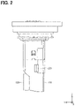
FIG. 2 is a side view of the flowmeter 10 viewed in a −X direction. The end opening 220 opens from the second passage 200 in the −X direction.
With reference to FIG. 1 again, the flow rate detector 300 is disposed on +Z side of the second passage 200. The flow rate detector 300 is configured to detect a flow rate of the fluid flowing through the second passage 200 from the first passage 100. In the cross-sectional view shown in FIG. 1, the flow rate detector 300 and its peripheral configurations are disposed on a far side (i.e., a +X side) of a surface of paper in FIG. 1, thus they are shown in dashed lines. In this embodiment, a type of the flow rate detector 300 is a hot wire type. The flow rate detector 300 may be a flap type or Karman vortex type flow rate detector.
FIG. 3 is a cross-sectional view of the flowmeter 10 taken along a XZ plane passing through the end opening 220. FIG. 3 is the cross-sectional view of the flowmeter 10 viewed in a direction of arrows III. The flowmeter 10 includes a throttle portion 340 facing the flow rate detector 300 in the X direction. The throttle portion 340 restricts a flow of the fluid passing through the flow rate detector 300. In the cross-section shown in FIG. 3, the flow rate detector 300 and the throttle portion 340 are located on a far side (i.e., +Y side) of a surface of paper in FIG. 3, thus the flow rate detector 300 and the throttle portion 340 are shown in dashed lines.
The flowmeter 10 includes a protrusion 230 protruding into the second passage 200 from a part of a wall surface of the second passage 200 between the flow rate detector 300 and the end opening 220. In this embodiment, the protrusion 230 protrudes in the −X direction from a portion of the wall surface located on +X side of the second passage 200. The portion of the wall surface located on the +X side of the second passage 200 is a facing surface that faces the end opening 220. The protrusion 230 protrudes in the −X direction from a portion of the wall surface located on the +X side and a +Y side of the second passage 200. A cross-sectional shape of the protrusion 230 taken along the XZ plane is triangular.
FIG. 4 illustrates a region R1 formed by projecting the end opening 220 in the X direction that is a direction along a center line (CL) of the end opening 220. The center line CL of the end opening 220 is a line passing through a center (i.e, a gravity center) of a cross-section of a part of the end opening 220 on a +X side of the end opening 220 and a center (i.e, a gravity center) of a cross-section of a part of the end opening 220 on a −X side of the end opening 220. In this embodiment, the protrusion 230 does not overlap with the region R1 of the wall surface defining the second passage 200. The protrusion 230 is formed into a shape such that a flow resistance of the fluid flowing from the flow rate detector 300 to the end opening 220 is less than a flow resistance of the fluid flowing from the end opening 220 to the flow rate detector 300.
The flowmeter 10 is configured to detect a flow rate of the fluid flowing through the intake pipe IP in the +Y direction (i.e., a forward direction). That is, the flow rate detector 300 detects a flow rate of a part of the fluid having flown into the first passage 100 through the first opening 110 and flowing to the end opening 220. Thus, if the fluid flows into the flowmeter 10 through the end opening 220 to the first passage 100, a measurement error of the flow rate detector 300 may occur. As shown in FIG. 1, the flowmeter 10 includes the protrusion 230. Thus, even if the fluid flows into the flowmeter 10 through the end opening 220, the fluid is reflected at the protrusion 230 and a vortex VTa is generated (see FIG. 3), which can restrict the fluid from flowing into the flowmeter 10 in the backward direction.
A flowmeter 10 p of a comparative example shown in FIG. 5 differs from the flowmeter 10 of the first embodiment in that the flowmeter 10 p does not include the protrusion 230. Other portions are similar to those of the first embodiment. The same reference numerals as those in the first embodiment indicate the same configurations with the first embodiment, and references are made to the preceding description. FIG. 6 is a cross-sectional view of the flowmeter 10 p taken along the XZ plane passing through the end opening 220.
The flowmeter 10 p of the comparative example does not include the protrusion 230. Thus, as shown in a flow CF1 in FIG. 6, the fluid flowing into the flowmeter 10 p through the end opening 220 flows toward the first passage 100. This leads to a measurement error of the flow rate detector 300. In contrast, the flowmeter 10 of the first embodiment includes the protrusion 230. Thus, even if the fluid flows into the flowmeter 10 through the end opening 220, the fluid is reflected at the protrusion 230 and a vortex VTa is generated, so that the fluid is restricted from flowing into the flowmeter 10 in the backward direction. Therefore, the measurement error of the flow rate detector 300 can be reduced by restricting the fluid from flowing into the flowmeter 10 in the backward direction.
In the flowmeter 10 of the first embodiment, the protrusion 230 protrudes in the −X direction from a portion of the wall surface of the second passage 200 located on the +X side of the second passage 200. Compared to a case in which the protrusion 230 is located in a portion of the wall surface of the second passage 200 that is different from the portion of the wall surface located on the +X side of the second passage 200, a passage axis of the second passage 200 can be greatly changed at the protrusion 230 and the protrusion 230 can easily block a flow of the fluid flowing into the flowmeter 10 through the end opening 220. Therefore, the vortex VTa is likely to generate.
In the flowmeter 10 of the first embodiment, the protrusion 230 is disposed in a portion of the wall surface of the second passage 200 that does not overlap with the region R1. Therefore, compared to a case in which the protrusion 230 is located within the region R1, the protrusion 230 is likely to block the fluid flowing into the flowmeter 10 through the end opening 220. Thus, the vortex VTa is likely to generate.
The protrusion 230 is formed into a shape such that a flow resistance of the fluid flowing from the flow rate detector 300 to the end opening 220 is less than a flow resistance of the fluid flowing from the end opening 220 to the flow rate detector 300. Thus, the protrusion 230 blocks the fluid flowing into the flowmeter 10 through the end opening 220 and the vortex VTa is likely generated while the fluid flows smoothly into the first passage 100 toward the end opening 220.
B. Second Embodiment
As shown in FIG. 7, a flowmeter 12 of a second embodiment differs from the flowmeter 10 of the first embodiment in that the flowmeter 12 does not include the protrusion 230, the flowmeter 12 includes an end opening 220 a and an end opening 220 b in place of the end opening 220, and the flowmeter 12 includes a partition 240. Other portions are similar to those of the first embodiment. The same reference numerals as those in the first embodiment indicate the same configurations with the first embodiment and a reference is made to the preceding descriptions.
The end opening 220 a opens from the second passage 200 in the −X direction. The end opening 220 b opens from the second passage 200 in the +X direction. The end opening 220 a and the end opening 220 b are rectangular openings that have the same size.
The partition 240 separates the end opening 220 a from the end opening 220 b. In other words, when the end opening 220 a is viewed from a +X side of the end opening 220 a, the end opening 220 b is invisible behind the partition 240. When the end opening 220 b is viewed from a −X side of the end opening 220 b, the end opening 220 a is also invisible behind the partition 240. The partition 240 includes a thin portion 242 and a thick portion 244. The thin portion 242 is a portion of the partition overlapping with the end opening 220 a and the end opening 220 b. The thick portion 244 is a portion of the partition 240 between the flow rate detector 300 and the thin portion 242. The thin portion 242 is thinner than the thick portion 244. FIG. 8 is a view illustrating a portion facing the end opening 220 a and the end opening 220 b. The portion facing the end opening 220 a and the end opening 220 b is a portion of the partition 240 located within a region R2. The region R2 is formed by projecting the end opening 220 a and the end opening 220 b in the X direction that is a center line direction of the end opening 220 a and the end opening 220 b.
The flowmeter 12 includes the partition 240. Thus, even if the fluid flows into the flowmeter 12 through the end opening 220 a and the end opening 220 b, the fluid flowing along the thin portion 242 is reflected at the thick portion 244 of the partition 240 to generate a vortex VTb. As a result, the fluid is restricted from flowing into the flowmeter 10 in the backward direction.
As shown in FIG. 9, a flowmeter 12 p of a comparative example differs from the flowmeter 12 of the second embodiment in that the flowmeter 12 p does not include the partition 240. Other configurations are similar to those of the second embodiment. The same reference numerals as those in the second embodiment show the same configurations and references are made to the preceding descriptions.
Since the flowmeter 12 p of the comparative example does not include the partition 240, the fluid flowing into the flowmeter 12 p through the end opening 220 a and the end opening 220 b flows toward the flow rate detector 300 as shown in a flow CF2. Such generation of the flow CF2 leads to the measurement error of the flow rate detector 300. In contrast, the flowmeter 12 of the second embodiment includes the partition 240. Thus, even if the fluid flows into the flowmeter 12 through the end opening 220 a and the end opening 220 b, the fluid flowing along the thin portion 242 is reflected at the thick portion 244 of the partition 240 to generate the vortex VTb. As a result, the fluid is restricted from flowing into the flowmeter 12 in the backward direction. Therefore, the measurement error of the flow rate detector 300 can be reduced by restricting the fluid from flowing into the flowmeter 12 in the backward direction.
C. Third Embodiment
As shown in FIG. 10, a flowmeter 14 of a third embodiment differs from the flowmeter 12 of the second embodiment in that the flowmeter 14 does not include the partition 240 and includes an end opening 220 c and an end opening 220 d in place of the end opening 220 a and the end opening 220 b. Other configurations are similar to those of the flowmeter 12 of the second embodiment. The same reference numerals as those in the second embodiment indicate the same configurations with the second embodiment and references are made to the preceding descriptions.
The end opening 220 c opens from the second passage 200 in the −X direction. The end opening 220 d opens from the second passage 200 in the +X direction. A direction in which the end opening 220 c and the end opening 220 d face each other is defined as the X direction. The end opening 220 c and the end opening 220 d have opening end surfaces. The opening end surface of the end opening 220 c and the opening end surface of the end opening 220 d are tilted toward the same side relative to a facing line CD that connects between two centers of the end opening 220 c and the end opening 220 d. That the opening end surfaces are tilted toward the same side relative to the facing line CD means that components of the slopes of the opening end surfaces relative to the facing line CD have the same correlation. For example, in the flowmeter 14 in FIG. 10, both a line segment Lc showing the slope of the opening end surface of the end opening 220 c and a line segment Ld showing the slope of the opening end surface of the end opening 220 d have negative correlation between a component in the X axis and a component in a Z axis. That is, the line segment Lc and the line segment Ld extend from the +Z side to the −Z side as extending from the −X side to +X side, which means both the line segment Lc and the line segment Ld have negative correlation between the X direction and the Y direction. It is only required that the line segments have the same correlation. Thus, the line segment Lc may have a slope that is different from a slope of the line segment Ld. That is, the line segment Lc and the line segment Ld are not necessarily parallel to each other. The slope of the opening end surface of the end opening 220 c and the slope of the opening end surface of the end opening 220 d are not limited to have negative correlations between the X direction and the Z direction. The slope of the opening end surface of the end opening 220 c and the slope of the opening end surface of the end opening 220 d may have positive correlations between the X direction and the Y direction.
FIG. 11 illustrates a state of the flowmeter 14 when the fluid flows into the flowmeter 14 through the end opening 220 c and the end opening 220 d. When the fluid flows into the flowmeter 14 through the end opening 220 c and the end opening 220 d, the fluid flowing into the flowmeter 14 through the end opening 220 c and the fluid flowing into the flowmeter 14 through the end opening 220 d face each other to generate a shear stress. The shear stress is likely to generate a vortex VTc. The vortex VTc restricts the fluid from flowing into the flowmeter 14 through the end opening 220 c and the end opening 220 d, so that the measurement error of the flow rate detector 300 can be reduced.
D. Fourth Embodiment
As shown in FIG. 12, a flowmeter 16 of a fourth embodiment differs from the flowmeter 14 of the third embodiment in that the flowmeter 16 includes a recess 260. Other configurations are similar to those of the third embodiment. The same reference numerals with those in the third embodiment show the same configurations in the third embodiment and references are made to the preceding descriptions.
The recess 260 is entirely disposed within a range Rd of the wall surface of the second passage 200. The range Rd is formed by projecting the end opening 220 d onto the wall surface of the second passage 200 along the line segment Ld.
FIG. 13 illustrates a state of the flowmeter 16 where the fluid flows into the flowmeter 16 through the end opening 220 c and the end opening 220 d. When the fluid flows into the flowmeter 16 through the end opening 220 c and the end opening 220 d, the fluid flowing into the flowmeter 16 through the end opening 220 c and the fluid flowing into the flowmeter 16 through the end opening 220 d face each other to generate a shear stress. The shear stress is likely to generate a vortex VTd. Additionally, a flow of the fluid flowing into the flowmeter 16 through the end opening 220 d is reversed along the recess 260, which assists to generate the vortex VTd.
E. Fifth Embodiment
As shown in FIG. 14, a flowmeter 18 of a fifth embodiment differs from the flowmeter 16 of the fourth embodiment in that the flowmeter 18 includes a protrusion 280 in place of the recess 260. Other configurations are similar to those of the fourth embodiment. The same reference numerals as those in the fourth embodiment show the same configurations with the fourth embodiment and references are made to the preceding descriptions.
The protrusion 280 protrudes from a portion of the wall surface of the second passage 200 into the second passage 200. The portion of the wall surface is entirely disposed within the region Rd.
FIG. 15 illustrates a state of the flowmeter 18 where the fluid flows into the flowmeter 18 through the end opening 220 c and the end opening 220 d. When the fluid flows into the flowmeter 18 through the end opening 220 c and the end opening 220 d, the fluid flowing into the flowmeter 18 through the end opening 220 c and the fluid flowing into the flowmeter 18 through the end opening 220 d face each other to generate a shear stress. The shear stress is likely to generate a vortex VTe. A flow of the fluid flowing into the flowmeter 18 through the end opening 220 d is reversed by reflecting at the protrusion 280, which assists to generate the vortex VTe.
F. Other Embodiments
As shown in FIG. 16, a flowmeter 10 a of a sixth embodiment shown in FIG. 16 differs from the flowmeter 10 of the first embodiment in that the flowmeter 10 a includes a protrusion 230 a that is different from the protrusion 230. In the first embodiment, the protrusion 230 protrudes from a portion of the wall surface located on the +X side and +Y side of the second passage 200, but the present disclosure is not limited to this. The protrusion 230 a protrudes in the −X direction from a portion of the wall surface located on the +X side and the −Y side of the second passage 200. A cross-sectional shape of the protrusion 230 a taken along the XZ plane is triangular. The flowmeter 10 a of the sixth embodiment can obtain the same advantages as those of the first embodiment.
As shown in FIG. 17, a flowmeter 10 b of a seventh embodiment differs from the flowmeter 10 of the first embodiment in that the flowmeter 10 b includes a protrusion 230 b that is different from the protrusion 230. The protrusion 230 b protrudes in the −X direction from a facing surface of the wall surface that faces the end opening 220 and is located on the +X side of the second passage 200. The protrusion 230 b extends entirely in the Y direction in a portion of the second passage 200. A cross-sectional shape of the protrusion 230 b taken along the XZ plane is triangular. The flowmeter 10 b of the seventh embodiment can obtain the same advantages as those of the first embodiment.
As shown in FIGS. 18 to 22, flowmeters 10 c-10 g of eighth to twelfth embodiments differ from the flowmeter 10 of the first embodiment in that they include protrusions 230 c to 230 g that are different from the protrusion 230. Other configurations are similar to those of the first embodiment. A cross-sectional shape of each of the protrusions taken along the XZ plane is not limited to the shape of the first embodiment and may be a shape as shown in protrusions 230 c to 230 g in FIGS. 18 to 22. The flowmeter 10 c to 10 g of the eighth to twelfth embodiments can obtain the same advantages as those of the first embodiment.
As shown in FIGS. 23 to 28, flowmeters 12 a to 12 g of thirteenth to eighteenth embodiments differ from the flowmeter 12 of the second embodiment in that they include partitions 240 a to 240 f that are different from the partition 240 of the second embodiment. Other configurations are similar to those of the second embodiment. A shape of the partition is not limited to the shape in the second embodiment and may be shapes of partitions 240 a to 240 f shown in FIGS. 23 to 28. The flowmeters 12 a to 12 f of the thirteenth to eighteenth embodiments can obtain the same advantages as those of the second embodiment. The partition may be formed into a shape such that the flow resistance of the fluid flowing from the flow rate detector 300 to the end opening 220 a and the end opening 220 b is less than the flow resistance of the fluid flowing from the end opening 220 a and the end opening 220 b to the flow rate detector 300. The flowmeter having such partition can make it easy to generate a vortex by blocking the fluid flowing into the flowmeter through the end opening 220 by the protrusion 230 while the fluid flows smoothly into the first passage 100 toward the end opening 220.
As shown in FIGS. 29-31, flowmeters of nineteenth to twenty-first embodiments differ from the flowmeter 16 of the fourth embodiment in that they include recesses 260 a to 260 c that are different from the recess 260. Other configurations are similar to those of the configurations in the fourth embodiment. A shape of the recess 260 is not limited to the shape shown in the fourth embodiment and may be a shape defined by a combination of flat surfaces as described in the recess 260 a in FIG. 29. In the fourth embodiment, the recess 260 is entirely disposed within the range Rd of the wall surface of the second passage 200, but the present disclosure is not limited to this. As described in a recess 260 b in FIG. 30, a portion of the recess 260 b may be disposed in the range Rc of the wall surface of the second passage 200. The range Rc is formed by projecting the end opening 220 c onto the wall surface of the second passage 200 along the line segment Lc. The number of the recesses 260 is not limited to one as shown in the fourth embodiment, and the number of the recesses 260 may be two as shown in the recess 260 a and the recess 260 c in FIG. 31. The flowmeters 16 a to 16 c of the nineteenth to twenty-first embodiment can obtain the same advantages as those of the fourth embodiment.
As shown in FIGS. 32 to 35, flowmeters 18 a to 18 d of twenty-second to twenty-fifth embodiments differ from the flowmeter 18 of the fifth embodiment in that they include protrusions 280 a to 280 e that are different from the protrusion 280. Other configurations are similar to those of the fifth embodiment. A shape of the protrusion 280 is not limited to a shape in the fifth embodiment and may be shapes as described in the protrusion 280 a and the protrusion 280 b shown in FIGS. 32 to 33. In the fifth embodiment, the entire of the protrusion 280 protrudes into the second passage 200 from a portion of the wall surface of the second passage 200 within the range Rd, but the present disclosure is not limited to this. As shown in the protrusion 280 c in FIG. 34, a part of the protrusion 280 c may protrude from the portion of the wall surface of the second passage 200 within the range Rc. The number of the protrusions 280 is not limited one as shown in the fifth embodiment. The number of the protrusions may be two like the protrusion 280 d and the protrusion 280 e as shown in FIG. 35. The flowmeters 18 a to 18 d of the twenty-second to the twenty-fifth embodiments can obtain the same advantages as those of the fifth embodiment.
As shown in FIGS. 36 to 38, flowmeters 20 a to 20 c in twenty-sixth to twenty-eighth embodiments are modifications of a thermal type flowmeter disclosed in WO2017/073276 A1. Regarding the flowmeters 20 a to 20 c shown in FIGS. 36 to 38, only a second outlet 313, a front side sub passage recess 330, and a flow rate detector 602 are donated by reference numerals in the same configuration with the thermal type flow meter without modification. Each of the flowmeters 20 a to 20 c includes a protrusion 230 h to 230 k that protrudes from a wall surface of the front side sub passage recess 330 between the flow rate detector 602 and the second outlet 313 Also in the flowmeters 20 a to 20 c, even if the fluid flows into the flowmeters 20 a to 20 c through the second outlet 313, the fluid is reflected at the protrusions 230 h to 230 k to generate a vortex, so that the fluid is restricted from flowing into the flowmeters 20 a to 20 c through the second outlet 313.
A flowmeter 30 of a twenty-ninth embodiment in FIG. 39 is a modification of a device disclosed in JP 2004-519690 A. Regarding the flowmeter 30 in FIG. 39, only a measurement element 9, an inlet opening 21, an exhaust opening 33, a turning guide passage 51, and an outlet opening 54 are donated by reference numerals in the same configurations with the device without modification for descriptive purposes. The flowmeter 30 includes a protrusion 230 m protruding from a wall surface of the turning guide passage 51 between the measurement element 9 and the outlet opening 54. Also in the flowmeter 30, even if the fluid flows into the flowmeter 30 through the outlet opening 54, the fluid is reflected at the protrusion 230 m to generate a vortex, so that the fluid is restricted from flowing into the flowmeter 30 through the outlet opening 54 in the backward direction.
A flowmeter of a thirtieth embodiment includes the protrusion 280 of the flowmeter 18 of the fifth embodiment compared to the flowmeter 16 of the fourth embodiment shown in FIG. 12. That is, the flowmeter is not limited to a configuration in which the flowmeter includes either the recess 260 or the protrusion 280 and may have both the recess 260 and the protrusion 280.
The present disclosure should not be limited to the embodiments described above and modifications and various other embodiments may be implemented without departing from the scope of the present disclosure. For example, the technical features in each embodiment corresponding to the technical features in the form described in the summary may be used to solve some or all of the above-described problems, or to provide one of the above-described effects. In order to achieve a part or all, replacement or combination can be appropriately performed. Also, if the technical features are not described as essential in the present specification, they can be deleted as appropriate.

Claims (11)

What is claimed is:
1. A flowmeter disposed in a passage through which a fluid flows, the flowmeter comprising:
a first passage defining an opening through which a part of the fluid flows into the flowmeter from the passage; and
a second passage branching off from the first passage and including a flow rate detector that is configured to detect a flow rate of the fluid flowing through the second passage from the first passage, wherein
the second passage has one end at which the second passage branches off from the first passage and the other end opposite to the one end,
the second passage includes:
at least one end opening at the other end of the second passage; and
an inflow reducer configured to restrict the fluid from flowing into the second passage through the at least one end opening,
the second passage has a single end opening as the at least one end opening,
the inflow reducer is a protrusion protruding into the second passage from a wall surface of the second passage,
the wall surface is a part of the second passage between the flow rate detector and the single end opening, and
the protrusion has a cross-section having a quadrangle shape or a triangle shape.
2. The flowmeter according to claim 1, wherein
the wall surface has a facing surface that faces the single end opening, and
the protrusion protrudes from the facing surface.
3. The flowmeter according to claim 1, wherein
when the single end opening is projected onto the wall surface in a direction along a center line of the single end opening, the protrusion does not overlap with a projection of the single end opening on the wall surface.
4. The flowmeter according to claim 1, wherein
the protrusion is formed into a shape such that a flow resistance of the fluid flowing from the flow rate detector to the single end opening is less than a flow resistance of the fluid flowing from the single end opening to the flow rate detector.
5. A flowmeter disposed in a passage through which a fluid flows, the flowmeter comprising:
a first passage defining an opening through which a part of the fluid flows into the flowmeter from the passage; and
a second passage branching off from the first passage and including a flow rate detector that is configured to detect a flow rate of the fluid flowing through the second passage from the first passage, wherein
the second passage has one end at which the second passage branches off from the first passage and the other end opposite to the one end,
the second passage includes:
at least one end opening at the other end of the second passage; and
an inflow reducer configured to restrict the fluid from flowing into the second passage through the at least one end opening,
the second passage has two end openings facing each other as the at least one end opening,
the inflow reducer is a partition that partitions off one of the two end openings from the other of the two end openings,
the partition includes:
a thin portion that is a portion of the partition overlapping with the two end openings; and
a thick portion that is a portion of the partition between the flow rate detector and the thin portion, and
the thin portion is thinner than the thick portion.
6. The flowmeter according to claim 5, wherein
the partition is formed into a shape such that a flow resistance of the fluid flowing from the flow rate detector to the two end openings is less than a flow resistance of the fluid flowing from the two end openings to the flow rate detector.
7. A flowmeter disposed in a passage through which a fluid flows, the flowmeter comprising:
a first passage defining an opening through which a part of the fluid flows into the flowmeter from the passage; and
a second passage branching off from the first passage and including a flow rate detector that is configured to detect a flow rate of the fluid flowing through the second passage from the first passage, wherein
the second passage has one end at which the second passage branches off from the first passage and the other end opposite to the one end,
the second passage includes:
at least one end opening at the other end of the second passage; and
an inflow reducer configured to restrict the fluid from flowing into the second passage through the at least one end opening,
the second passage has two end openings facing each other as the at least one end opening,
each of the two end openings has an opening end surface,
the opening end surface of each of the two end openings serves as the inflow reducer, and
the opening end surface of one of the two end openings and the opening end surface of the other of the two end openings are tilted toward a same side relative to a facing line that connects between two centers of the two end openings.
8. The flowmeter according to claim 7, further comprising a recess, wherein
when at least one of the two end openings is projected onto a wall surface of the second passage along a tilting direction of the opening end surface of the at least one of the two end openings, at least a part of the recess is recessed from a projection of the at least one of the two end openings on the wall surface.
9. The flowmeter according to claim 7, further comprising
a protrusion, wherein
when at least one of the two end openings is projected onto a wall surface of the second passage along a tilting direction of the opening end surface of the at least one of the two end openings, at least a part of the protrusion protrudes into the second passage from a projection of the at least one of the two end openings on the wall surface.
10. The flowmeter according to claim 7, further comprising
a recess and a protrusion, wherein
when at least one of the two end openings is projected onto a wall surface of the second passage along a tilting direction of the opening end surface of the at least one of the two end openings,
at least a part of the recess is recessed from a projection of the at least one of the two end openings on the wall surface, and
at least a part of the protrusion protrudes into the second passage from the projection on the wall surface.
11. A flowmeter disposed in a passage through which a fluid flows, the flowmeter comprising:
a first passage defining an opening through which a part of the fluid flows into the flowmeter from the passage; and
a second passage branching off from the first passage and including a flow rate detector that is configured to detect a flow rate of the fluid flowing through the second passage from the first passage, wherein
the second passage has one end at which the second passage branches off from the first passage and the other end opposite to the one end,
the second passage includes:
at least one end opening at the other end of the second passage; and
an inflow reducer configured to restrict the fluid from flowing into the second passage through the at least one end opening,
the second passage has a single end opening as the at least one end opening,
the inflow reducer is a protrusion protruding into the second passage from a wall surface of the second passage,
the wall surface is a part of the second passage between the flow rate detector and the single end opening,
the protrusion has a peak away from the wall surface of the second passage, and
the peak of the protrusion is offset toward the single end opening.
US17/173,642 2018-08-14 2021-02-11 Flowmeter Active US11326918B2 (en)

Applications Claiming Priority (4)

Application Number Priority Date Filing Date Title
JP2018152603A JP7068095B2 (en) 2018-08-14 2018-08-14 Flow measuring device
JPJP2018-152603 2018-08-14
JP2018-152603 2018-08-14
PCT/JP2019/022359 WO2020035988A1 (en) 2018-08-14 2019-06-05 Flow rate measurement device

Related Parent Applications (1)

Application Number Title Priority Date Filing Date
PCT/JP2019/022359 Continuation WO2020035988A1 (en) 2018-08-14 2019-06-05 Flow rate measurement device

Publications (2)

Publication Number Publication Date
US20210164819A1 US20210164819A1 (en) 2021-06-03
US11326918B2 true US11326918B2 (en) 2022-05-10

Family

ID=69525384

Family Applications (1)

Application Number Title Priority Date Filing Date
US17/173,642 Active US11326918B2 (en) 2018-08-14 2021-02-11 Flowmeter

Country Status (4)

Country Link
US (1) US11326918B2 (en)
JP (1) JP7068095B2 (en)
DE (1) DE112019004102T8 (en)
WO (1) WO2020035988A1 (en)

Cited By (1)

* Cited by examiner, † Cited by third party
Publication number Priority date Publication date Assignee Title
US20210341324A1 (en) * 2019-01-15 2021-11-04 Denso Corporation Air flow rate measurement device

Citations (24)

* Cited by examiner, † Cited by third party
Publication number Priority date Publication date Assignee Title
JPH06307906A (en) 1993-04-28 1994-11-04 Hitachi Ltd Air flow rate measuring equipment
JPH1114420A (en) 1997-06-23 1999-01-22 Hitachi Ltd Heating resistor type air flow measurement device
JP2000213974A (en) * 1999-01-25 2000-08-04 Hitachi Ltd Heating resistance type flow measurement device and internal combustion engine control device
US20030094041A1 (en) * 2001-11-19 2003-05-22 Takao Iwaki Apparatus for measuring flow amount
US20030159501A1 (en) 2001-04-20 2003-08-28 Erhard Renninger Device for determining at least one parameter of a medium flowing in a conduit
JP2006047272A (en) 2004-06-29 2006-02-16 Ngk Spark Plug Co Ltd Flow sensor
US7124626B2 (en) * 2002-09-30 2006-10-24 Robert Bosch Gmbh Device for determining at least one parameter of a medium flowing in a line
US20070068246A1 (en) * 2005-09-29 2007-03-29 Mitsubishi Denki Kabushiki Kaisha Flow rate measuring apparatus
US7260986B2 (en) * 2002-10-02 2007-08-28 Robert Bosch Gmbh Airflow meter with device for the separation of foreign particles
JP2012057975A (en) 2010-09-06 2012-03-22 Hitachi Automotive Systems Ltd Flow measurement device
US20130008243A1 (en) * 2011-07-07 2013-01-10 Denso Corporation Air flow measuring device
US20130019675A1 (en) * 2011-07-19 2013-01-24 Denso Corporation Flow measuring device
WO2013187229A1 (en) * 2012-06-15 2013-12-19 日立オートモティブシステムズ株式会社 Thermal flow meter
JP5646030B1 (en) * 2013-10-11 2014-12-24 三菱電機株式会社 Flow measuring device
WO2016027551A1 (en) * 2014-08-22 2016-02-25 日立オートモティブシステムズ株式会社 Thermal flow meter
US20160313165A1 (en) * 2015-04-21 2016-10-27 Denso Corporation Airflow measuring device
JP2017083317A (en) 2015-10-28 2017-05-18 日立オートモティブシステムズ株式会社 Thermal type flowmeter
US20170356775A1 (en) * 2016-06-14 2017-12-14 Denso Corporation Flow measuring device
US20180113015A1 (en) * 2016-10-25 2018-04-26 Mitsubishi Electric Corporation Flow measuring device
WO2018193764A1 (en) * 2017-04-19 2018-10-25 株式会社デンソー Physical quantity measuring device
US20190120674A1 (en) 2015-10-28 2019-04-25 Hitachi Automotive Systems, Ltd. Thermal flow meter
WO2020066424A1 (en) * 2018-09-25 2020-04-02 株式会社デンソー Flow rate measurement device
US20210172780A1 (en) * 2018-08-24 2021-06-10 Denso Corporation Flowmeter
DE112019004678T5 (en) * 2018-09-19 2021-06-24 Denso Corporation Flow meter

Family Cites Families (1)

* Cited by examiner, † Cited by third party
Publication number Priority date Publication date Assignee Title
US7509855B2 (en) 2007-07-25 2009-03-31 The Lubrizol Corporation Sensor manifolds

Patent Citations (24)

* Cited by examiner, † Cited by third party
Publication number Priority date Publication date Assignee Title
JPH06307906A (en) 1993-04-28 1994-11-04 Hitachi Ltd Air flow rate measuring equipment
JPH1114420A (en) 1997-06-23 1999-01-22 Hitachi Ltd Heating resistor type air flow measurement device
JP2000213974A (en) * 1999-01-25 2000-08-04 Hitachi Ltd Heating resistance type flow measurement device and internal combustion engine control device
US20030159501A1 (en) 2001-04-20 2003-08-28 Erhard Renninger Device for determining at least one parameter of a medium flowing in a conduit
US20030094041A1 (en) * 2001-11-19 2003-05-22 Takao Iwaki Apparatus for measuring flow amount
US7124626B2 (en) * 2002-09-30 2006-10-24 Robert Bosch Gmbh Device for determining at least one parameter of a medium flowing in a line
US7260986B2 (en) * 2002-10-02 2007-08-28 Robert Bosch Gmbh Airflow meter with device for the separation of foreign particles
JP2006047272A (en) 2004-06-29 2006-02-16 Ngk Spark Plug Co Ltd Flow sensor
US20070068246A1 (en) * 2005-09-29 2007-03-29 Mitsubishi Denki Kabushiki Kaisha Flow rate measuring apparatus
JP2012057975A (en) 2010-09-06 2012-03-22 Hitachi Automotive Systems Ltd Flow measurement device
US20130008243A1 (en) * 2011-07-07 2013-01-10 Denso Corporation Air flow measuring device
US20130019675A1 (en) * 2011-07-19 2013-01-24 Denso Corporation Flow measuring device
WO2013187229A1 (en) * 2012-06-15 2013-12-19 日立オートモティブシステムズ株式会社 Thermal flow meter
JP5646030B1 (en) * 2013-10-11 2014-12-24 三菱電機株式会社 Flow measuring device
WO2016027551A1 (en) * 2014-08-22 2016-02-25 日立オートモティブシステムズ株式会社 Thermal flow meter
US20160313165A1 (en) * 2015-04-21 2016-10-27 Denso Corporation Airflow measuring device
JP2017083317A (en) 2015-10-28 2017-05-18 日立オートモティブシステムズ株式会社 Thermal type flowmeter
US20190120674A1 (en) 2015-10-28 2019-04-25 Hitachi Automotive Systems, Ltd. Thermal flow meter
US20170356775A1 (en) * 2016-06-14 2017-12-14 Denso Corporation Flow measuring device
US20180113015A1 (en) * 2016-10-25 2018-04-26 Mitsubishi Electric Corporation Flow measuring device
WO2018193764A1 (en) * 2017-04-19 2018-10-25 株式会社デンソー Physical quantity measuring device
US20210172780A1 (en) * 2018-08-24 2021-06-10 Denso Corporation Flowmeter
DE112019004678T5 (en) * 2018-09-19 2021-06-24 Denso Corporation Flow meter
WO2020066424A1 (en) * 2018-09-25 2020-04-02 株式会社デンソー Flow rate measurement device

Cited By (2)

* Cited by examiner, † Cited by third party
Publication number Priority date Publication date Assignee Title
US20210341324A1 (en) * 2019-01-15 2021-11-04 Denso Corporation Air flow rate measurement device
US11747183B2 (en) * 2019-01-15 2023-09-05 Denso Corporation Air flow rate measurement device

Also Published As

Publication number Publication date
WO2020035988A1 (en) 2020-02-20
DE112019004102T5 (en) 2021-06-02
JP7068095B2 (en) 2022-05-16
US20210164819A1 (en) 2021-06-03
JP2020027060A (en) 2020-02-20
DE112019004102T8 (en) 2021-07-29

Similar Documents

Publication Publication Date Title
US9217655B2 (en) Sensor system for determining at least one flow property of a fluid medium flowing in a main flow direction
US11053877B2 (en) Air flow rate measuring device
EP1179726A2 (en) Split-flow-type flowmeter
JP5338864B2 (en) Air flow measurement device
JP2003502682A (en) Device for measuring the amount of flowing medium
US11326918B2 (en) Flowmeter
US20070062276A1 (en) Device for determining at least one parameter of a medium flowing in a conduit
US20210270649A1 (en) Ultrasonic flow meter
US10928231B2 (en) Thermal flow meter with housing surfaces that minimize vortex formation
US20160312753A1 (en) Flow rate meter
US10859418B2 (en) Airflow measuring device
US10605639B2 (en) Flow rate measuring device
JP2022084957A (en) Physical quantity measuring device
JP2002005713A (en) Air flow measuring device
US20210172780A1 (en) Flowmeter
JP2003315116A (en) Flow measurement device
US10684150B2 (en) Flow measuring device
WO2020066424A1 (en) Flow rate measurement device
US11009378B2 (en) Flow rate measuring device
JP6927342B2 (en) Air flow measuring device
JPH11229979A (en) Air cleaner
JP4006463B2 (en) Flow rate measuring module and internal combustion engine control method
JPH11211528A (en) Air intake device
JP2000009513A (en) Flow measurement device and air cleaner
JPH02307016A (en) Vortex flowmeter

Legal Events

Date Code Title Description
AS Assignment

Owner name: DENSO CORPORATION, JAPAN

Free format text: ASSIGNMENT OF ASSIGNORS INTEREST;ASSIGNORS:UEDA, KAZUAKI;YOSHIDA, YUUSUKE;ITO, KENGO;SIGNING DATES FROM 20210113 TO 20210118;REEL/FRAME:055233/0419

FEPP Fee payment procedure

Free format text: ENTITY STATUS SET TO UNDISCOUNTED (ORIGINAL EVENT CODE: BIG.); ENTITY STATUS OF PATENT OWNER: LARGE ENTITY

STPP Information on status: patent application and granting procedure in general

Free format text: APPLICATION DISPATCHED FROM PREEXAM, NOT YET DOCKETED

STPP Information on status: patent application and granting procedure in general

Free format text: DOCKETED NEW CASE - READY FOR EXAMINATION

STPP Information on status: patent application and granting procedure in general

Free format text: NON FINAL ACTION MAILED

STPP Information on status: patent application and granting procedure in general

Free format text: RESPONSE TO NON-FINAL OFFICE ACTION ENTERED AND FORWARDED TO EXAMINER

STPP Information on status: patent application and granting procedure in general

Free format text: NOTICE OF ALLOWANCE MAILED -- APPLICATION RECEIVED IN OFFICE OF PUBLICATIONS

STPP Information on status: patent application and granting procedure in general

Free format text: PUBLICATIONS -- ISSUE FEE PAYMENT RECEIVED

STPP Information on status: patent application and granting procedure in general

Free format text: PUBLICATIONS -- ISSUE FEE PAYMENT VERIFIED

STCF Information on status: patent grant

Free format text: PATENTED CASE

FEPP Fee payment procedure

Free format text: MAINTENANCE FEE REMINDER MAILED (ORIGINAL EVENT CODE: REM.); ENTITY STATUS OF PATENT OWNER: LARGE ENTITY