US11325141B2 - Spray nozzle and sprayer - Google Patents
Spray nozzle and sprayer Download PDFInfo
- Publication number
- US11325141B2 US11325141B2 US16/999,847 US202016999847A US11325141B2 US 11325141 B2 US11325141 B2 US 11325141B2 US 202016999847 A US202016999847 A US 202016999847A US 11325141 B2 US11325141 B2 US 11325141B2
- Authority
- US
- United States
- Prior art keywords
- water outlet
- fan blade
- connecting pipe
- liquid
- spray nozzle
- Prior art date
- Legal status (The legal status is an assumption and is not a legal conclusion. Google has not performed a legal analysis and makes no representation as to the accuracy of the status listed.)
- Active
Links
Images


Classifications
-
- B—PERFORMING OPERATIONS; TRANSPORTING
- B05—SPRAYING OR ATOMISING IN GENERAL; APPLYING FLUENT MATERIALS TO SURFACES, IN GENERAL
- B05B—SPRAYING APPARATUS; ATOMISING APPARATUS; NOZZLES
- B05B3/00—Spraying or sprinkling apparatus with moving outlet elements or moving deflecting elements
- B05B3/02—Spraying or sprinkling apparatus with moving outlet elements or moving deflecting elements with rotating elements
- B05B3/10—Spraying or sprinkling apparatus with moving outlet elements or moving deflecting elements with rotating elements discharging over substantially the whole periphery of the rotating member
- B05B3/105—Fan or ventilator arrangements therefor
-
- B—PERFORMING OPERATIONS; TRANSPORTING
- B05—SPRAYING OR ATOMISING IN GENERAL; APPLYING FLUENT MATERIALS TO SURFACES, IN GENERAL
- B05B—SPRAYING APPARATUS; ATOMISING APPARATUS; NOZZLES
- B05B7/00—Spraying apparatus for discharge of liquids or other fluent materials from two or more sources, e.g. of liquid and air, of powder and gas
- B05B7/0075—Nozzle arrangements in gas streams
-
- B—PERFORMING OPERATIONS; TRANSPORTING
- B05—SPRAYING OR ATOMISING IN GENERAL; APPLYING FLUENT MATERIALS TO SURFACES, IN GENERAL
- B05B—SPRAYING APPARATUS; ATOMISING APPARATUS; NOZZLES
- B05B7/00—Spraying apparatus for discharge of liquids or other fluent materials from two or more sources, e.g. of liquid and air, of powder and gas
- B05B7/02—Spray pistols; Apparatus for discharge
- B05B7/04—Spray pistols; Apparatus for discharge with arrangements for mixing liquids or other fluent materials before discharge
- B05B7/0416—Spray pistols; Apparatus for discharge with arrangements for mixing liquids or other fluent materials before discharge with arrangements for mixing one gas and one liquid
- B05B7/0483—Spray pistols; Apparatus for discharge with arrangements for mixing liquids or other fluent materials before discharge with arrangements for mixing one gas and one liquid with gas and liquid jets intersecting in the mixing chamber
-
- A—HUMAN NECESSITIES
- A01—AGRICULTURE; FORESTRY; ANIMAL HUSBANDRY; HUNTING; TRAPPING; FISHING
- A01M—CATCHING, TRAPPING OR SCARING OF ANIMALS; APPARATUS FOR THE DESTRUCTION OF NOXIOUS ANIMALS OR NOXIOUS PLANTS
- A01M7/00—Special adaptations or arrangements of liquid-spraying apparatus for purposes covered by this subclass
- A01M7/0003—Atomisers or mist blowers
- A01M7/0017—Portable atomisers, e.g. knapsack type
-
- A—HUMAN NECESSITIES
- A01—AGRICULTURE; FORESTRY; ANIMAL HUSBANDRY; HUNTING; TRAPPING; FISHING
- A01M—CATCHING, TRAPPING OR SCARING OF ANIMALS; APPARATUS FOR THE DESTRUCTION OF NOXIOUS ANIMALS OR NOXIOUS PLANTS
- A01M7/00—Special adaptations or arrangements of liquid-spraying apparatus for purposes covered by this subclass
- A01M7/005—Special arrangements or adaptations of the spraying or distributing parts, e.g. adaptations or mounting of the spray booms, mounting of the nozzles, protection shields
- A01M7/006—Mounting of the nozzles
-
- B—PERFORMING OPERATIONS; TRANSPORTING
- B05—SPRAYING OR ATOMISING IN GENERAL; APPLYING FLUENT MATERIALS TO SURFACES, IN GENERAL
- B05B—SPRAYING APPARATUS; ATOMISING APPARATUS; NOZZLES
- B05B12/00—Arrangements for controlling delivery; Arrangements for controlling the spray area
- B05B12/16—Arrangements for controlling delivery; Arrangements for controlling the spray area for controlling the spray area
-
- B—PERFORMING OPERATIONS; TRANSPORTING
- B05—SPRAYING OR ATOMISING IN GENERAL; APPLYING FLUENT MATERIALS TO SURFACES, IN GENERAL
- B05B—SPRAYING APPARATUS; ATOMISING APPARATUS; NOZZLES
- B05B15/00—Details of spraying plant or spraying apparatus not otherwise provided for; Accessories
- B05B15/60—Arrangements for mounting, supporting or holding spraying apparatus
- B05B15/65—Mounting arrangements for fluid connection of the spraying apparatus or its outlets to flow conduits
- B05B15/652—Mounting arrangements for fluid connection of the spraying apparatus or its outlets to flow conduits whereby the jet can be oriented
-
- B—PERFORMING OPERATIONS; TRANSPORTING
- B05—SPRAYING OR ATOMISING IN GENERAL; APPLYING FLUENT MATERIALS TO SURFACES, IN GENERAL
- B05B—SPRAYING APPARATUS; ATOMISING APPARATUS; NOZZLES
- B05B15/00—Details of spraying plant or spraying apparatus not otherwise provided for; Accessories
- B05B15/60—Arrangements for mounting, supporting or holding spraying apparatus
- B05B15/68—Arrangements for adjusting the position of spray heads
-
- B—PERFORMING OPERATIONS; TRANSPORTING
- B05—SPRAYING OR ATOMISING IN GENERAL; APPLYING FLUENT MATERIALS TO SURFACES, IN GENERAL
- B05B—SPRAYING APPARATUS; ATOMISING APPARATUS; NOZZLES
- B05B3/00—Spraying or sprinkling apparatus with moving outlet elements or moving deflecting elements
- B05B3/02—Spraying or sprinkling apparatus with moving outlet elements or moving deflecting elements with rotating elements
- B05B3/10—Spraying or sprinkling apparatus with moving outlet elements or moving deflecting elements with rotating elements discharging over substantially the whole periphery of the rotating member
- B05B3/1064—Spraying or sprinkling apparatus with moving outlet elements or moving deflecting elements with rotating elements discharging over substantially the whole periphery of the rotating member the liquid or other fluent material to be sprayed being axially supplied to the rotating member through a hollow rotating shaft
-
- B—PERFORMING OPERATIONS; TRANSPORTING
- B05—SPRAYING OR ATOMISING IN GENERAL; APPLYING FLUENT MATERIALS TO SURFACES, IN GENERAL
- B05B—SPRAYING APPARATUS; ATOMISING APPARATUS; NOZZLES
- B05B9/00—Spraying apparatus for discharge of liquids or other fluent material, without essentially mixing with gas or vapour
- B05B9/03—Spraying apparatus for discharge of liquids or other fluent material, without essentially mixing with gas or vapour characterised by means for supplying liquid or other fluent material
- B05B9/04—Spraying apparatus for discharge of liquids or other fluent material, without essentially mixing with gas or vapour characterised by means for supplying liquid or other fluent material with pressurised or compressible container; with pump
- B05B9/08—Apparatus to be carried on or by a person, e.g. of knapsack type
- B05B9/0805—Apparatus to be carried on or by a person, e.g. of knapsack type comprising a pressurised or compressible container for liquid or other fluent material
- B05B9/0811—Apparatus to be carried on or by a person, e.g. of knapsack type comprising a pressurised or compressible container for liquid or other fluent material comprising air supplying means actuated by the operator to pressurise or compress the container
Definitions
- This application relates to agricultural field, and more particularly to a spray nozzle and a sprayer.
- a spray nozzle usually atomizes a liquid by directly ejecting it from the nozzle, during which full contact of the liquid with an inner wall of the nozzle is not allowed. This causes uneven distribution of the liquid in the spray nozzle and thus leads to unsatisfactory liquid atomization, failing to meet the needs of users.
- the present application aims to provide a spray nozzle and sprayer with better liquid atomization.
- the present application provides a spray nozzle, comprising:
- the fan blade assembly is connected to the transmission component; the fan blade assembly rotates with respect to the transmission component to create a vacuum inside the fan blade assembly, so that a liquid to be atomized under atmospheric pressure enters the fan blade assembly through the transmission component; and the fan blade assembly drives the liquid in the fan blade assembly to rotate so as to atomize the liquid and eject it from the fan blade assembly.
- the fan blade assembly comprises a fan blade and a water outlet; the water outlet is connected to the fan blade; the water outlet is hollow; the transmission component passes through the fan blade and extends into the water outlet; the water outlet is rotatable with the fan blade to rotate with respect to the transmission component, so as to create a vacuum inside the water outlet, and thus the liquid enters the water outlet through the transmission component under atmospheric pressure; and the water outlet is able to drive the liquid in the water outlet to rotate so as to atomize the liquid and eject it from the water outlet.
- the fan blade assembly further comprises a connecting pipe; both of the fan blade and the water outlet are sleeved on the connecting pipe; the transmission component is inserted into an end of the connecting pipe; the fan blade rotates with respect to the transmission component to drive the water outlet to rotate via the connecting pipe; and the liquid is able to enter the water outlet through the transmission component and the connecting pipe under atmospheric pressure.
- an inner diameter of the water outlet is flared toward an end of the water outlet away from the fan blade.
- At least one first opening is provided on a side wall of the connecting pipe; and the first opening is configured to communicate an interior of the connecting pipe with an interior of the water outlet; and the liquid is able to enter the water outlet through the transmission component, the connecting pipe and the first opening under atmospheric pressure.
- a plurality of first openings spaced apart are provided on the side wall of the connecting pipe.
- an inner wall of the water outlet is provided with a first thread; an outer wall of the connecting pipe is provided with a second thread; and the first thread and the second thread are joined together to fixedly connect the water outlet and the connecting pipe.
- the spray nozzle further comprises a bearing sleeved on the fan blade assembly; and the fan blade assembly is rotatably connected to the transmission component through the bearing.
- the present application further provides a sprayer, comprising:
- the sprayer body is connected to the transmission component and is configured to accommodate the liquid to be atomized.
- the fan blade assembly can rotate with respect to the transmission component to create a vacuum inside the fan blade assembly, so that the liquid in an outer container under atmospheric pressure can enter the fan blade assembly through the transmission component and then is atomized and ejected by rotating with the fan blade assembly.
- the liquid in the fan blade assembly rotates with the fan blade assembly, so that the liquid fully contacts with the inner wall of the fan blade assembly, which makes the liquid evenly distribute inside the spray nozzle, resulting in better liquid atomization.
- FIG. 1 is an exploded view of a spray nozzle according to an embodiment
- FIG. 2 is a cross-sectional view of the spray nozzle according to an embodiment
- FIG. 3 is an axonometric view of the spray nozzle according to an embodiment
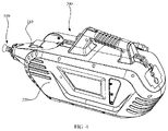
- FIG. 4 is an axonometric view of a sprayer according to an embodiment
- FIG. 5 is an axonometric view of a sprayer with a spray nozzle casing according to an embodiment
- FIG. 6 is a cross-sectional view of a sprayer provided with the spray nozzle casing according to an embodiment
- FIG. 7 is an axonometric view of the spray nozzle and an air blower according to an embodiment
- FIG. 8 is a cross-sectional view of the spray nozzle and the air blower according to an embodiment
- FIG. 9 schematically shows the cooperation between a bulge and a fixing assembly according to an embodiment.
- FIG. 10 is a cross-sectional view of the spray nozzle and the spray nozzle casing according to an embodiment.
- the recitation “and/or” in the description includes three solutions, for example, the recitation “A and/or B” includes the technical solution A, the technical solution B and the technical incorporation of A and B.
- the technical solutions of various embodiments can be combined, but it is required that these combinations can be implemented by those of ordinary skill in the art. Otherwise, when there is conflict in the combination of technical solutions or it is impossible to combine the technical solution, the combination of the technical solutions is considered to be nonexistent and does not fall within the scope as defined by the appended claims.
- a spray nozzle which is specifically described as follows.
- a spray nozzle 100 in an embodiment includes a transmission component 1 and a fan blade assembly 2 .
- the fan blade assembly 2 is connected to the transmission component 1 .
- the fan blade assembly 2 can rotate with respect to the transmission component 1 to create a vacuum inside the fan blade assembly 2 , so that a liquid to be atomized under atmospheric pressure can enter the fan blade assembly 2 through the transmission component 1 .
- the fan blade assembly 2 can drive the liquid in the fan blade assembly 2 to rotate so as to atomize the liquid and eject it from the fan blade assembly 2 .
- the fan blade assembly 2 can rotate with respect to the transmission component 1 to create a vacuum inside the fan blade assembly 2 , so that the liquid under atmospheric pressure can enter the fan blade assembly 2 through the transmission component 1 and then be atomized and ejected by rotating with the fan blade assembly 2 .
- the liquid in the fan blade assembly 2 rotates together with the fan blade assembly 2 so that the liquid is uniformly distributed inside the fan blade assembly 2 , thereby obtaining better liquid atomization.
- the fan blade assembly 2 includes a fan blade 21 and a water outlet 22 .
- the water outlet 22 is connected to the fan blade 21 .
- the transmission component 1 passes through the fan blade 21 and extends into the water outlet 22 .
- the water outlet 22 rotates together with the fan blade 21 with respect to the transmission component 1 to create a vacuum inside the water outlet 22 , so that the liquid to be atomized under atmospheric pressure can enter the water outlet 22 through the transmission component 1 .
- the water outlet 22 can drive the liquid in the water outlet 22 to rotate so as to atomize the liquid and eject it from the water outlet 22 .
- the rotation of the fan blade 21 induces a force to blow the liquid sprayed from the water outlet 22 , so that the liquid is further atomized and ejected farther.
- the fan blade assembly 2 further includes a connecting pipe 23 . Both of the fan blade 21 and the water outlet 22 are sleeved on the connecting pipe 23 .
- the transmission component 1 is inserted into an end of the connecting pipe 23 .
- the fan blade 21 can rotate with respect to the transmission component 1 to drive the water outlet 22 to rotate via the connecting pipe 23 , and the liquid can enter the water outlet 22 through the transmission component 1 and the connecting pipe 23 under atmospheric pressure.
- an inner diameter of the water outlet 22 is flared toward an end of the water outlet 22 away from the fan blade 21 , which helps disperse the liquid in the water outlet 22 outward, making the liquid distribution more even and obtaining better liquid atomization.
- the water outlet 22 is not limited to be trumpet-shaped.
- the transmission component 1 includes a first side surface 11 and a first end surface 12 .
- the connecting pipe 23 includes a second side surface 231 oriented toward the first side surface 11 and a second end surface 232 oriented toward the first end surface 12 .
- a first gap exists between the first end surface 12 and the second end surface 232 .
- a second gap exists between the first side surface 11 and the second side surface 231 . The first gap and the second gap together constitute a gap.
- an inner wall of the water outlet 22 is provided with a first thread 221 .
- An outer wall of the connecting pipe 23 is provided with a second thread 233 .
- the first thread 221 and the second thread 233 are joined together to fixedly connect the water outlet 22 and the connecting pipe 23 .
- the first thread 221 is an internal thread
- the second thread 233 is an external thread.
- the transmission component 1 includes a first cavity 13 .
- the connecting pipe 23 includes a second cavity 234 .
- the first cavity 13 is communicated with the second cavity 234 .
- the second cavity 234 is communicated with an interior of the water outlet 22 so that the liquid can enter the water outlet 22 through the first cavity 13 and the second cavity 234 .
- the first cavity 13 is not limited to a cylinder. In the case that the first cavity 13 is cylindrical in shape, the liquid flows faster through the first cavity 13 , and the load applied in the first cavity 13 is uniformly distributed.
- the second cavity 234 is not limited to a cylinder. In the case that the second cavity 234 is cylindrical in shape, the liquid flows faster through the second cavity 234 , and the load applied in the second cavity 234 is uniformly distributed.
- At least one first opening 235 is provided on a side wall of the connecting pipe 23 .
- the first opening 235 is configured to communicate the second cavity 234 and the interior of the water outlet 22 .
- the liquid can enter the water outlet 22 through the first cavity 13 , the second cavity 234 and the first opening 235 .
- the first opening 235 is not limited to a circular opening.
- a plurality of first openings 235 spaced apart are provided on the side wall of the connecting pipe 23 , which allows the liquid in the second cavity 234 to enter the water outlet 22 in different directions, and thus the liquid is more dispersed in the water outlet 22 , enhancing liquid atomization.
- four first openings 235 spaced apart are provided on the side wall of the connecting pipe 23 , which allows the liquid in the second cavity 234 to enter the water outlet in different directions. It should be understood that, in other embodiments, the number of the first openings 235 may be less than three or more than five, and the specific number may be selected reasonably according to actual conditions.
- the spray nozzle 100 further includes a bearing 3 sleeved on the fan blade assembly 2 .
- the bearing 3 is configured to support the fan blade assembly 2 that is rotatably connected to the transmission component 1 through the bearing 3 .
- the bearing 3 is sleeved on the connecting pipe 23 .
- One end of the bearing 3 is in contact with the connecting pipe 23 .
- the other end of the bearing 3 is in contact with an end of the fan blade 21 away from the water outlet 22 .
- the fan blade 21 and the connecting pipe 23 together limit movement of the bearing 3 in an axial direction.
- the spray nozzle 100 still further includes a bearing locating part 4 sleeved on the bearing 3 .
- the bearing locating part 4 is configured to fix the bearing 3 and is connected to the transmission component 1 .
- the fan blade assembly 2 is connected to the transmission component 1 via the bearing 3 and the bearing locating part 4 .
- the spray nozzle 100 further includes at least one fastener 5 .
- the fastener 5 passes through the transmission component 1 to connect the bearing locating part 4 .
- the bearing locating part 4 and the transmission component 1 are connected via the fastener 5 .
- the plurality of fasteners 5 pass through the transmission component 1 to connect the bearing locating part 4 , so as to realize the reliable connection between the bearing locating part 4 and the transmission component 1 .
- the three fasteners 5 pass through the transmission component 1 to connect the bearing locating part 4 .
- the number of the fasteners 5 may be less than two or more than four, and the specific number may be selected reasonably according to actual conditions.
- the fasteners 5 is not limited to a screw.
- the bearing 3 includes an inner ring 31 and an outer ring 32 .
- the outer ring 32 is rotatably sleeved on the inner ring 31
- the inner ring 31 is sleeved on the connecting pipe 23 .
- the bearing locating part 4 is sleeved on the outer ring 32 .
- the rotation of the fan blade 21 drives the connection pipe 23 and the water outlet 22 to rotate
- the connection pipe 23 drives the inner ring 31 to rotate. Since the outer ring 32 does not rotate with the inner ring 31 , the transmission component 1 that connects the bearing 3 via the bearing locating part 4 will not rotate with the inner ring 31 . That is, when the fan blade assembly 2 that includes the fan blade 21 , the connecting pipe 23 and the water outlet 22 rotates, the transmission component 1 does not follow the fan blade assembly 2 to rotate.
- An external driving device drives the fan blade assembly 2 , so as to drive the water outlet 22 to rotate.
- the water outlet 22 rotates and thus creates a partial vacuum therein. Under atmospheric pressure, the liquid enters the water outlet 22 through the first cavity 13 , the second cavity 234 and the first opening 235 .
- the liquid in the water outlet 22 rotates with the water outlet 22 and then is atomized and ejected from the water outlet 22 .
- the atomized liquid is subjected to fan blade-induced wind forces and thus is further atomized and ejected farther.
- a sprayer which is specifically described as follows.
- the sprayer includes the spray nozzle 100 and a sprayer body 200 .
- the sprayer body 200 is connected to the transmission component 1 and is configured to accommodate the liquid to be atomized.
- the sprayer body 200 can drive the fan blade assembly 2 to rotate with respect to the transmission component 1 , so as to create a vacuum inside the fan blade assembly 2 , whereby the liquid in the sprayer body 200 under atmospheric pressure can enter the fan blade assembly 2 through the transmission component 1 .
- the fan blade assembly 2 can also drive the liquid in the fan blade assembly 2 to rotate so as to atomize the liquid and eject it from the fan blade assembly 2 .
- the sprayer body 200 includes an air blower 210 and a sprayer casing 220 .
- One end of the air blower 210 is connected to the sprayer casing 220 , and the other end of the air blower 210 is connected to the transmission component 1 .
- the sprayer casing 220 is used to accommodate the liquid.
- the air blower 210 can drive the fan blade assembly 2 to rotate with respect to the transmission component 1 , so as to create a vacuum inside the fan blade assembly 2 , whereby the liquid in the sprayer under atmospheric pressure casing 220 can enter the fan blade assembly 2 through the transmission component 1 .
- the fan blade assembly 2 can also drive the liquid in the fan blade assembly 2 to rotate so as to atomize the liquid and eject it from the fan blade assembly 2 .
- the air blower 210 is rotatable with respect to the sprayer casing 220 to adjust an angle of the air blower 210 with respect to the sprayer casing 220 , so as to adjust an angle of the spray nozzle 100 connected to the air blower 210 with respect to the sprayer casing 220 .
- an angle of the spray nozzle 100 with respect to the sprayer casing 220 different spray angles can be achieved without moving the whole sprayer, widening the spray angle and facilitating the use of the sprayer.
- a mesh structure 211 is provided on a side of the air blower 210 that faces the sprayer casing 220 .
- the mesh structure 211 is used to communicate the air blower 210 and external environment. External air can enter the air blower 210 through the mesh structure 211 .
- the mesh structure 211 can prevent large-sized objects from entering the air blower 210 to ensure the normal operation of the air blower.
- the sprayer 200 further includes a spray nozzle casing 300 .
- the spray nozzle 100 is arranged in the spray nozzle casing 300 that is connected to the sprayer casing 220 .
- the spray nozzle 100 also includes at least one extension part 6 provided on an outer wall of the transmission component 1 .
- the transmission component 1 is connected to the spray nozzle casing 300 via the extension part 6 .
- a plurality of extension parts 6 spaced apart are provided on the outer wall of the transmission component 1 , which makes the connection between the transmission component 1 and the spray nozzle casing 300 more reliable.
- three extension parts 6 spaced apart are arranged on the outer wall of the transmission component 1 . It should be understood that, in other embodiments, the number of the extension parts 6 may be less than two or more than four, and the specific number may be selected reasonably according to actual conditions.
- the sprayer body 200 also includes a container 230 provided in the sprayer casing 220 to accommodate the liquid.
- the container 230 partially protrudes from the sprayer casing 220 .
- a part of the container 230 that protrudes from the sprayer casing 220 is provided with an opening that communicates with an interior of the container 230 . In this way, the liquid can be injected into the container 230 from the opening.
- the sprayer body 200 further includes a container lid 240 provided at the opening of the container 230 . Specifically, after the liquid is injected into the container 230 , the container lid 240 covers the opening of the container 230 to prevent splashing when the sprayer is in use and prevent contamination from entering the container 230 .
- the sprayer body 200 still further includes a power supply provided in the sprayer casing 220 .
- the power supply is electrically connected to the air blower 210 for energy supply.
- the sprayer body 200 yet further includes a case 250 provided in the sprayer casing 220 to accommodate the power supply.
- the case 250 and the container 230 spaced apart are provided.
- the case 250 is provided to separate the power supply and the liquid in the container 230 , so as to avoid electrical short circuit, thereby improving the safety of the power supply.
- the sprayer body 200 also includes wires, by which the power supply is electrically connected to the air blower 210 .
- the sprayer also includes a first tubular component. An end of the first tubular component is connected to the transmission component 1 , and the other end of the first tubular component is inserted into the sprayer casing 220 . The liquid in the sprayer casing 220 can enter the fan blade assembly 2 through the first tubular component and the transmission component 1 .
- the sprayer further includes a second tubular component.
- An end of the second tubular component is inserted into the air blower 210 , and the other end of the second tubular component is inserted into the container 230 .
- the second tubular component is used to pass the wind pressure generated by the air blower 210 into the container 230 , so as to result in a greater pressure in the container 230 .
- the water outlet 22 rotates with respect to the transmission component 1 to create a vacuum inside the water outlet 22 , so that the liquid to be atomized under atmospheric pressure can enter the water outlet 22 through the transmission component 1 .
- the second tubular component is used to pass the wind pressure generated by the air blower 210 into the container 230 , so as to result in a greater pressure in the container 230 , whereby the liquid in the container 230 flows into the fan blade assembly 2 more quickly.
- the sprayer body 200 also includes at least one adjustment element 260 .
- the air blower 210 is connected to the sprayer casing 220 via the adjustment element 260 .
- the adjustment element 260 is rotatable with respect to the sprayer casing 220 to adjust an angle of the air blower 210 with respect to the sprayer casing 220 , so as to adjust an angle of the spray nozzle 100 connected to the air blower 210 with respect to the sprayer casing 220 .
- the adjustment element 260 is cylindrical.
- a plurality of adjustment elements 260 spaced apart are provided on the air blower 210 , which makes the connection between the air blower 210 and the sprayer casing 220 more reliable.
- two adjustment elements 260 spaced apart are provided on the air blower 210 . It should be understood that, in other embodiments, the number of adjustment elements 260 may be more than three, and the specific number may be selected reasonably according to actual conditions.
- the adjustment element 260 is provided with a second opening 261 configured to allow at least one of the first tubular component, the second tubular component and the wires to extend into the sprayer casing 220 .
- the second opening 261 includes a first sub-opening 2611 , a second sub-opening 2612 and a third sub-opening 2613 , which are spaced apart and provided on the adjustment element 260 .
- the first tubular component passes through the first sub-opening 2611 to realize the connection between the transmission component 1 and the sprayer casing 220 .
- the second tubular component passes through the second sub-opening 2612 to realize the connection between the air blower 210 and the sprayer casing 220 .
- the wires pass through the third sub-opening 2613 to realize the electrical connection between the power supply and the air blower 210 .
- the first sub-opening 2611 , the second sub-opening 2612 and the third sub-opening 2613 are used to prevent the mutual interference among the first tubular component, the second tubular component and the wires.
- the container 230 is provided with two third openings 2301 .
- the first tubular component passes through the first sub-opening 2611 and one of the two third openings 2301 to realize the connection between the transmission component 1 and the sprayer casing 220 .
- the second tubular component passes through the second sub-opening 2612 and the other of the two third openings 2301 to realize the connection between the air blower 210 and the sprayer casing 220 .
- the sprayer still further includes a fixing assembly 400 for fixedly connecting the sprayer casing 220 and the adjustment element 260 .
- the fixing assembly 400 includes an elastic component 410 and a fixing block 420 .
- An end of the elastic component 410 is connected to the sprayer casing 220 , and the other end of the elastic component 410 is connected to the fixing block 420 .
- the fixing block 420 is connected to the adjustment element 260 that can rotate with respect to the fixing block 420 .
- the fixing block 420 can engage with different positions of an outer circumference of the adjustment element 260 .
- the elastic component 410 is used to provide an elastic force to engage the fixing block 420 with the adjustment element 260 .
- the elastic component 410 is not limited to a spring.
- the elastic component 410 is compressed in an initial state and is able to provide the elastic force to engage the fixing block 420 with the adjustment element 260 .
- the fixing block 420 is engaged with a first position of the adjustment element 260 , so that the air blower 210 is positioned at a first angle with respect to the sprayer casing 220 .
- an external force is applied to the spray nozzle 100 or the air blower 210 to drive the spray nozzle 100 and the air blower 210 to rotate together with respect to the sprayer casing 220 .
- the elastic force of the elastic component 410 is offset by the external force, and the adjustment element 260 is separated from the fixing block 420 and rotates with respect to the fixing block 420 .
- the elastic component 410 is further compressed.
- the spray nozzle 100 and the air blower 210 are rotated to a required second angle with respect to the sprayer casing 220 , the external force exerted on the spray nozzle 100 or the air blower 210 is removed.
- the elastic component 410 is elastically reset.
- the fixing block 420 is engaged with a second position of the adjustment element 260 under the elastic force of the elastic component 410 , thereby positioning the spray nozzle 100 and the air blower 210 at the second position with respect to the sprayer casing 220 .
- one end of the elastic component 410 is fixedly connected to the sprayer casing 220 , and the other end of the elastic component 410 is fixedly connected to the fixing block 420 . Therefore, when the adjustment element 260 rotates with respect to the fixing block 420 , the fixing block 420 does not follow the rotation of the adjustment element 260 .
- a plurality of first teeth 262 spaced apart are provided on the outer circumference of the adjustment element 260
- a plurality of second teeth 421 spaced apart are provided on a side of the fixing block 420 which faces the adjustment element 260 .
- the second teeth 421 can be engaged with different positions of the first teeth 262 to realize the engagement of the adjustment element 260 and the outer circumference of the fixing block 420 at different positions.
- the sprayer further includes a separator 500 provided between the sprayer casing 220 and the air blower 210 .
- the separator 500 is used to separate the sprayer casing 220 and the air blower 210 .
- the sprayer yet further includes a handle 600 provided on the sprayer casing 220 .
- the handle 600 helps to transfer the sprayer from one place to another.
- the sprayer also includes a switch button 700 provided on the sprayer casing 220 .
- the switch button 700 is used to control the start and stop of the air blower 210 .
- the switch button 700 is arranged on the handle 600 .
- the sprayer also includes a valve switch 800 provided on the sprayer casing 220 .
- the valve switch 800 is used to control the on and off of the first tubular component.
- the valve switch 800 is arranged on the handle 600 .
- the valve switch 800 and the switch button 700 are spaced apart. When the sprayer stops working, the valve switch 800 is closed to disconnect the first tubular component, thereby stopping the liquid in the container 230 from entering the fan blade assembly 2 and dripping out from the fan blade assembly 2 .
- the valve switch 800 is turned on to make the first tubular component communicated.
- the switch button 700 is turned on to start the air blower 210 .
- the air blower 210 can drive the fan blade assembly 2 to rotate to create a vacuum inside the fan blade assembly 2 .
- the liquid in the container 230 can enter the fan blade assembly 2 through the first tubular component under atmospheric pressure.
- the liquid in the fan blade assembly 2 follows the fan blade assembly 2 to rotate so as to atomize the liquid and eject it from the fan blade assembly 2 .
- the air blower 210 further atomizes the liquid sprayed from the fan blade assembly 2 and makes the atomized liquid be ejected farther.
- the spray nozzle 100 or the air blower 210 When the sprayer is in use, the spray nozzle 100 or the air blower 210 is rotated as needed, so that the spray nozzle 100 and the air blower 210 that are connected can rotate together with respect to the sprayer casing 220 , thereby adjusting the angle of the spray nozzle 100 relative to the sprayer casing 220 .
- the switch button 700 When the sprayer is not needed, the switch button 700 is turned off, and the air blower 210 stops working.
- the valve switch 800 is rotated to make the first tubular member disconnected.
Landscapes
- Life Sciences & Earth Sciences (AREA)
- Engineering & Computer Science (AREA)
- Insects & Arthropods (AREA)
- Pest Control & Pesticides (AREA)
- Wood Science & Technology (AREA)
- Zoology (AREA)
- Environmental Sciences (AREA)
- Structures Of Non-Positive Displacement Pumps (AREA)
Abstract
Description
Claims (7)
Applications Claiming Priority (2)
| Application Number | Priority Date | Filing Date | Title |
|---|---|---|---|
| CN202010740211.4A CN111760693A (en) | 2020-07-28 | 2020-07-28 | Spray head and sprayer |
| CN202010740211.4 | 2020-07-28 |
Publications (2)
| Publication Number | Publication Date |
|---|---|
| US20220032328A1 US20220032328A1 (en) | 2022-02-03 |
| US11325141B2 true US11325141B2 (en) | 2022-05-10 |
Family
ID=72148020
Family Applications (1)
| Application Number | Title | Priority Date | Filing Date |
|---|---|---|---|
| US16/999,847 Active US11325141B2 (en) | 2020-07-28 | 2020-08-21 | Spray nozzle and sprayer |
Country Status (3)
| Country | Link |
|---|---|
| US (1) | US11325141B2 (en) |
| EP (1) | EP3944899B1 (en) |
| CN (1) | CN111760693A (en) |
Families Citing this family (4)
| Publication number | Priority date | Publication date | Assignee | Title |
|---|---|---|---|---|
| CN111760690A (en) * | 2020-07-28 | 2020-10-13 | 士商(上海)机械有限公司 | Sprayer with a spray tube |
| CN113333198A (en) | 2021-07-09 | 2021-09-03 | 士商(上海)机械有限公司 | Knapsack sprayer |
| CN114158335A (en) * | 2021-10-20 | 2022-03-11 | 巧家县巧艳农业科技有限公司 | Fertile injection apparatus of hand-held type strawberry seedling foliar |
| CN118236791B (en) * | 2024-05-07 | 2025-04-04 | 江苏万皓建设科技集团有限公司 | An environmentally friendly sprinkler device for municipal engineering |
Citations (23)
| Publication number | Priority date | Publication date | Assignee | Title |
|---|---|---|---|---|
| US2607574A (en) * | 1946-03-15 | 1952-08-19 | Jr John W Hession | Aerosol generator |
| US4190207A (en) * | 1978-06-07 | 1980-02-26 | Teledyne Industries, Inc. | Pulsating spray apparatus |
| US4270698A (en) * | 1977-11-30 | 1981-06-02 | Karl Bisa | Aerosol forming device |
| US4473188A (en) * | 1981-01-06 | 1984-09-25 | Tecnoma | Machine for spraying a treatment liquid, especially for the treatment of plants and soils |
| US4795095A (en) * | 1986-09-08 | 1989-01-03 | Shepard Industries, Inc. | Rotary atomizer |
| US20020148909A1 (en) | 1999-04-12 | 2002-10-17 | Junkel Eric F. | Cooling device using fan-driven misting with large bottom fill port |
| US20060208102A1 (en) * | 2002-07-22 | 2006-09-21 | Nolte Hans J | High speed rotating atomizer assembly |
| US20080047591A1 (en) * | 2006-08-25 | 2008-02-28 | Seitz David M | Bell cup cleaning system and method |
| US20110000978A1 (en) * | 2005-06-06 | 2011-01-06 | Jean-Marc Chichep-Ortiche | Autonomous spraying device having a rotating disc |
| US20110036926A1 (en) * | 2009-08-11 | 2011-02-17 | Leno Ambrosio Nunes | Apparatus for Dispersing a Substance Over a Large Area |
| US20110089258A1 (en) * | 2009-10-21 | 2011-04-21 | John Yenkai Pun | Spray pattern modification with changes in sprayer design and methods |
| US20150258555A1 (en) * | 2012-09-28 | 2015-09-17 | Agco Corporation | Rotatable Shroud for Directional Control of Application Area |
| US20160121356A1 (en) * | 2013-05-22 | 2016-05-05 | Exel Industries | Nozzle support device having a rotary nozzle-carrying head |
| US9375734B1 (en) * | 2015-06-16 | 2016-06-28 | Efc Systems, Inc. | Coating apparatus turbine having internally routed shaping air |
| US20160332174A1 (en) * | 2015-05-14 | 2016-11-17 | Merial Inc. | Extended-range spray applicator |
| CN107552256A (en) | 2016-05-17 | 2018-01-09 | 尚宇新 | A kind of liquid atomizer |
| US9878337B1 (en) * | 2016-09-19 | 2018-01-30 | Smbure Co., Ltd. | Sprayer |
| US20180160670A1 (en) * | 2015-06-25 | 2018-06-14 | Pellenc (Societe Anonyme) | Spraying unit, compact spraying module including such a unit, and spraying and control system including a plurality of such modules |
| US20180168140A1 (en) * | 2015-06-25 | 2018-06-21 | Pellenc (Societe Anonyme) | Compact spraying module, system for spraying and controlling a plurality of such modules, and method for controlling modules of such a system |
| US20180339258A1 (en) * | 2017-05-29 | 2018-11-29 | Pil-Dong Jeon | Air cleaning apparatus with a moist filter |
| US20190176171A1 (en) * | 2016-06-23 | 2019-06-13 | Brendon Limited | Misting apparatus and method of use |
| US10632413B2 (en) * | 2013-12-30 | 2020-04-28 | Beijing China Science Organic Innovation Llc | Automatic high-speed rotary atomizing device and a fire extinguishing method by using the same |
| CN111282184A (en) | 2020-03-25 | 2020-06-16 | 应急管理部四川消防研究所 | An assembled automatic rotating nozzle |
Family Cites Families (7)
| Publication number | Priority date | Publication date | Assignee | Title |
|---|---|---|---|---|
| GB725083A (en) * | 1952-07-29 | 1955-03-02 | Svenska Flaektfabriken Ab | Apparatus for atomising and spraying liquids |
| GB2142844A (en) * | 1983-07-05 | 1985-01-30 | Edward Julius Bals | Sprayers |
| KR100651083B1 (en) * | 2005-12-13 | 2006-11-30 | 홍기술 | Chemical Spray Nozzle |
| CN201425031Y (en) * | 2009-04-16 | 2010-03-17 | 麦志坚 | Blowing fan with water mist function |
| KR101187634B1 (en) * | 2010-06-11 | 2012-10-05 | (주)캠스텍 | Compact atomization spray apparatus |
| KR101589068B1 (en) * | 2014-06-12 | 2016-01-28 | (주)캠스텍 | Chemical liquid spray system adjustable angle |
| CN212856238U (en) * | 2020-07-28 | 2021-04-02 | 士商(上海)机械有限公司 | Spray head and sprayer |
-
2020
- 2020-07-28 CN CN202010740211.4A patent/CN111760693A/en active Pending
- 2020-08-19 EP EP20191773.9A patent/EP3944899B1/en active Active
- 2020-08-21 US US16/999,847 patent/US11325141B2/en active Active
Patent Citations (24)
| Publication number | Priority date | Publication date | Assignee | Title |
|---|---|---|---|---|
| US2607574A (en) * | 1946-03-15 | 1952-08-19 | Jr John W Hession | Aerosol generator |
| US4270698A (en) * | 1977-11-30 | 1981-06-02 | Karl Bisa | Aerosol forming device |
| US4190207A (en) * | 1978-06-07 | 1980-02-26 | Teledyne Industries, Inc. | Pulsating spray apparatus |
| US4473188A (en) * | 1981-01-06 | 1984-09-25 | Tecnoma | Machine for spraying a treatment liquid, especially for the treatment of plants and soils |
| US4795095A (en) * | 1986-09-08 | 1989-01-03 | Shepard Industries, Inc. | Rotary atomizer |
| US20020148909A1 (en) | 1999-04-12 | 2002-10-17 | Junkel Eric F. | Cooling device using fan-driven misting with large bottom fill port |
| US20060208102A1 (en) * | 2002-07-22 | 2006-09-21 | Nolte Hans J | High speed rotating atomizer assembly |
| US20110000978A1 (en) * | 2005-06-06 | 2011-01-06 | Jean-Marc Chichep-Ortiche | Autonomous spraying device having a rotating disc |
| US20080047591A1 (en) * | 2006-08-25 | 2008-02-28 | Seitz David M | Bell cup cleaning system and method |
| US20110036926A1 (en) * | 2009-08-11 | 2011-02-17 | Leno Ambrosio Nunes | Apparatus for Dispersing a Substance Over a Large Area |
| US20110089258A1 (en) * | 2009-10-21 | 2011-04-21 | John Yenkai Pun | Spray pattern modification with changes in sprayer design and methods |
| US20150258555A1 (en) * | 2012-09-28 | 2015-09-17 | Agco Corporation | Rotatable Shroud for Directional Control of Application Area |
| US20160121356A1 (en) * | 2013-05-22 | 2016-05-05 | Exel Industries | Nozzle support device having a rotary nozzle-carrying head |
| US10632413B2 (en) * | 2013-12-30 | 2020-04-28 | Beijing China Science Organic Innovation Llc | Automatic high-speed rotary atomizing device and a fire extinguishing method by using the same |
| US20160332174A1 (en) * | 2015-05-14 | 2016-11-17 | Merial Inc. | Extended-range spray applicator |
| US9375734B1 (en) * | 2015-06-16 | 2016-06-28 | Efc Systems, Inc. | Coating apparatus turbine having internally routed shaping air |
| US20180160670A1 (en) * | 2015-06-25 | 2018-06-14 | Pellenc (Societe Anonyme) | Spraying unit, compact spraying module including such a unit, and spraying and control system including a plurality of such modules |
| US20180168140A1 (en) * | 2015-06-25 | 2018-06-21 | Pellenc (Societe Anonyme) | Compact spraying module, system for spraying and controlling a plurality of such modules, and method for controlling modules of such a system |
| CN107552256A (en) | 2016-05-17 | 2018-01-09 | 尚宇新 | A kind of liquid atomizer |
| CN107552256B (en) | 2016-05-17 | 2019-08-06 | 王招林 | A kind of liquid atomizer |
| US20190176171A1 (en) * | 2016-06-23 | 2019-06-13 | Brendon Limited | Misting apparatus and method of use |
| US9878337B1 (en) * | 2016-09-19 | 2018-01-30 | Smbure Co., Ltd. | Sprayer |
| US20180339258A1 (en) * | 2017-05-29 | 2018-11-29 | Pil-Dong Jeon | Air cleaning apparatus with a moist filter |
| CN111282184A (en) | 2020-03-25 | 2020-06-16 | 应急管理部四川消防研究所 | An assembled automatic rotating nozzle |
Also Published As
| Publication number | Publication date |
|---|---|
| EP3944899A1 (en) | 2022-02-02 |
| US20220032328A1 (en) | 2022-02-03 |
| EP3944899C0 (en) | 2024-01-31 |
| EP3944899B1 (en) | 2024-01-31 |
| CN111760693A (en) | 2020-10-13 |
Similar Documents
| Publication | Publication Date | Title |
|---|---|---|
| US11325141B2 (en) | Spray nozzle and sprayer | |
| US11890635B2 (en) | Sprayer | |
| US11324211B2 (en) | Sprayer | |
| CN109595360B (en) | Water channel switching device and water outlet device | |
| JPH01123650A (en) | Paint container/lid assembly of sprayer | |
| US4609148A (en) | Spraying equipment | |
| KR102494943B1 (en) | Sprayer | |
| US20220032329A1 (en) | Sprayer | |
| CN116569905B (en) | Aviation medicine application atomizer and control method thereof | |
| US20220226837A1 (en) | Water sprayer | |
| US4986477A (en) | Spray gun with adjustment of the shape of the jet | |
| TWI247631B (en) | Rotary atomizing spraying machine | |
| JP3238451U (en) | rotary atomizer | |
| GB2136321A (en) | Spraying equipment | |
| CN212856238U (en) | Spray head and sprayer | |
| CN217369580U (en) | Plasma cleaning machine shower nozzle, plasma cleaning machine spray gun and plasma cleaning machine | |
| CN212349247U (en) | Sprayer with a spray tube | |
| CN216826907U (en) | Rotary sprayer | |
| KR101524538B1 (en) | Air Vent Nozzle | |
| JP2021178267A (en) | Nozzle with bubble generation mechanism | |
| CN214811828U (en) | A paint-saving spray gun | |
| TWM594883U (en) | Hair dryer spray device | |
| CN223249604U (en) | A double spray button | |
| CN217938761U (en) | Change-over switch and atomizing device | |
| CN218820793U (en) | Humidifying device |
Legal Events
| Date | Code | Title | Description |
|---|---|---|---|
| FEPP | Fee payment procedure |
Free format text: ENTITY STATUS SET TO UNDISCOUNTED (ORIGINAL EVENT CODE: BIG.); ENTITY STATUS OF PATENT OWNER: SMALL ENTITY |
|
| FEPP | Fee payment procedure |
Free format text: ENTITY STATUS SET TO SMALL (ORIGINAL EVENT CODE: SMAL); ENTITY STATUS OF PATENT OWNER: SMALL ENTITY |
|
| STPP | Information on status: patent application and granting procedure in general |
Free format text: NOTICE OF ALLOWANCE MAILED -- APPLICATION RECEIVED IN OFFICE OF PUBLICATIONS |
|
| AS | Assignment |
Owner name: INTRADIN (SHANGHAI) MACHINERY CO., LTD., CHINA Free format text: ASSIGNMENT OF ASSIGNORS INTEREST;ASSIGNOR:WANG, GAOFENG;REEL/FRAME:059551/0789 Effective date: 20200817 |
|
| STPP | Information on status: patent application and granting procedure in general |
Free format text: PUBLICATIONS -- ISSUE FEE PAYMENT RECEIVED |
|
| STPP | Information on status: patent application and granting procedure in general |
Free format text: PUBLICATIONS -- ISSUE FEE PAYMENT VERIFIED |
|
| STCF | Information on status: patent grant |
Free format text: PATENTED CASE |
|
| MAFP | Maintenance fee payment |
Free format text: PAYMENT OF MAINTENANCE FEE, 4TH YR, SMALL ENTITY (ORIGINAL EVENT CODE: M2551); ENTITY STATUS OF PATENT OWNER: SMALL ENTITY Year of fee payment: 4 |