US11323311B2 - Radio communication system and radio base station - Google Patents
Radio communication system and radio base station Download PDFInfo
- Publication number
- US11323311B2 US11323311B2 US16/763,476 US201716763476A US11323311B2 US 11323311 B2 US11323311 B2 US 11323311B2 US 201716763476 A US201716763476 A US 201716763476A US 11323311 B2 US11323311 B2 US 11323311B2
- Authority
- US
- United States
- Prior art keywords
- scg
- cell group
- base station
- split bearer
- secondary cell
- Prior art date
- Legal status (The legal status is an assumption and is not a legal conclusion. Google has not performed a legal analysis and makes no representation as to the accuracy of the status listed.)
- Active, expires
Links
Images


Classifications
-
- H—ELECTRICITY
- H04—ELECTRIC COMMUNICATION TECHNIQUE
- H04L—TRANSMISSION OF DIGITAL INFORMATION, e.g. TELEGRAPHIC COMMUNICATION
- H04L41/00—Arrangements for maintenance, administration or management of data switching networks, e.g. of packet switching networks
- H04L41/06—Management of faults, events, alarms or notifications
- H04L41/0654—Management of faults, events, alarms or notifications using network fault recovery
- H04L41/0659—Management of faults, events, alarms or notifications using network fault recovery by isolating or reconfiguring faulty entities
- H04L41/0661—Management of faults, events, alarms or notifications using network fault recovery by isolating or reconfiguring faulty entities by reconfiguring faulty entities
-
- H04L41/0672—
-
- H—ELECTRICITY
- H04—ELECTRIC COMMUNICATION TECHNIQUE
- H04W—WIRELESS COMMUNICATION NETWORKS
- H04W76/00—Connection management
- H04W76/10—Connection setup
- H04W76/15—Setup of multiple wireless link connections
- H04W76/16—Involving different core network technologies, e.g. a packet-switched [PS] bearer in combination with a circuit-switched [CS] bearer
-
- H—ELECTRICITY
- H04—ELECTRIC COMMUNICATION TECHNIQUE
- H04W—WIRELESS COMMUNICATION NETWORKS
- H04W72/00—Local resource management
- H04W72/04—Wireless resource allocation
-
- H—ELECTRICITY
- H04—ELECTRIC COMMUNICATION TECHNIQUE
- H04W—WIRELESS COMMUNICATION NETWORKS
- H04W76/00—Connection management
- H04W76/10—Connection setup
- H04W76/18—Management of setup rejection or failure
-
- H—ELECTRICITY
- H04—ELECTRIC COMMUNICATION TECHNIQUE
- H04W—WIRELESS COMMUNICATION NETWORKS
- H04W76/00—Connection management
- H04W76/10—Connection setup
- H04W76/19—Connection re-establishment
-
- H—ELECTRICITY
- H04—ELECTRIC COMMUNICATION TECHNIQUE
- H04W—WIRELESS COMMUNICATION NETWORKS
- H04W76/00—Connection management
- H04W76/30—Connection release
-
- H—ELECTRICITY
- H04—ELECTRIC COMMUNICATION TECHNIQUE
- H04W—WIRELESS COMMUNICATION NETWORKS
- H04W76/00—Connection management
- H04W76/30—Connection release
- H04W76/34—Selective release of ongoing connections
-
- H—ELECTRICITY
- H04—ELECTRIC COMMUNICATION TECHNIQUE
- H04W—WIRELESS COMMUNICATION NETWORKS
- H04W88/00—Devices specially adapted for wireless communication networks, e.g. terminals, base stations or access point devices
- H04W88/02—Terminal devices
- H04W88/06—Terminal devices adapted for operation in multiple networks or having at least two operational modes, e.g. multi-mode terminals
Definitions
- the present invention relates to a radio communication system and a radio base station capable of setting a split bearer.
- LTE Long Term Evolution
- NR 5G New Radio
- Non-Patent Document 1 as a type of bearer adapted to dual connectivity (DC) using a radio base station of the LTE system and a radio base station of the NR system, a split bearer that passes via a secondary cell group (SCG) (Split bearer via SCG) has been defined.
- SCG secondary cell group
- the master base station is a radio base station of the LTE system (hereinafter, “LTE MeNB”) and the secondary base station is a radio base station of the NR system (hereinafter, “NR SgNB” or simply “SgNB”)
- LTE MeNB radio base station of the LTE system
- NR SgNB radio base station of the NR system
- a bearer for a user plane (S1-U) between the core network and the radio base station is set only between the core network (EPC (Evolved Packet Core)) and the NR SgNB.
- EPC Evolved Packet Core
- User data (for example, downlink data) is transmitted from the LTE MeNB and the NR SgNB to a user equipment (UE) via this split bearer.
- UE user equipment
- Non-Patent Document 1 when the secondary base station is the radio base station of the NR system (NR SgNB), a case is prescribed in Non-Patent Document 1 in which the LTE MeNB forms a macro cell and the NR SgNB forms a small cell.
- the active state of the PSCell and SCell that is, the connected state (RRC Connected state) in the radio resource control layer (RRC layer) is maintained.
- RRC Connected state the radio resource control layer
- One object of the present invention is to provide a radio communication system and a radio base station that can, when setting a split bearer that passes via the secondary cell group (SCG), simultaneously achieve both the suppressing of the increase of the signaling amount due to repeated release and setting of a split bearer and reduction of the power consumption of the user equipment.
- SCG secondary cell group
- a radio communication system is a radio communication system (radio communication system 10 ) in which a split bearer (split bearer B SP ) that passes from a core network (core network 20 ) to a secondary cell group (SCG) and branches from other radio base station (for example, gNB 100 B) included in the secondary cell group to a radio base station (for example, eNB 100 A) included in a master cell group (MCG) is set, and in which data is transmitted to a user equipment (UE 200 ) via thus set split bearer.
- a split bearer split bearer
- split bearer B SP split bearer that passes from a core network (core network 20 ) to a secondary cell group (SCG) and branches from other radio base station (for example, gNB 100 B) included in the secondary cell group to a radio base station (for example, eNB 100 A) included in a master cell group (MCG) is set, and in which data is transmitted to a user equipment (UE 200 ) via thus set split bearer.
- the radio base station includes a failure notification receiving unit (failure notification receiving unit 130 ) that receives from the user equipment a failure notification (SCG Failure Information) that indicates that a radio link failure (S-RLF) has occurred in the secondary cell group; and a connection control unit (connection control unit 120 ) that, when the failure notification receiving unit has received the failure notification, transmits to the other radio base station a resource change request (Secondary Node Modification Request) to instruct to release the resource of the split bearer of a predetermined layer (for example, RLC layer) and the layers below thereof in the secondary cell group.
- a failure notification receiving unit 130 receives from the user equipment a failure notification (SCG Failure Information) that indicates that a radio link failure (S-RLF) has occurred in the secondary cell group
- SCG Failure Information failure notification
- connection control unit 120 connection control unit that, when the failure notification receiving unit has received the failure notification, transmits to the other radio base station a resource change request (Secondary Node Modification Request) to instruct to
- the other radio base station includes a resource control unit (resource control unit 140 ) that releases the resource of the split bearer of the predetermined layer and the layers below thereof in the secondary cell group based on the received resource change request.
- the connection control unit deletes setting itself of the secondary cell group when a bearer belonging to the secondary cell group other than the split bearer is not set.
- a radio base station is a radio base station in which a split bearer that passes from a core network to a secondary cell group and branches from other radio base station included in the secondary cell group to the radio base station included in a master cell group is set, and that transmits data to a user equipment via thus set split bearer.
- the radio base station includes a failure notification receiving unit that receives from the user equipment a failure notification that indicates that a radio link failure has occurred in the secondary cell group; and a connection control unit that, when the failure notification receiving unit has received the failure notification, transmits to the other radio base station a resource change request to instruct to release the resource of the split bearer of a predetermined layer and the layers below thereof in the secondary cell group.
- the connection control unit deletes setting itself of the secondary cell group when a bearer belonging to the secondary cell group other than the split bearer is not set.
- FIG. 1 is an overall schematic configuration diagram of a radio communication system 10 .
- FIG. 2 is a diagram showing a protocol stack of eNB 100 A (LTE MeNB) and gNB 100 B (NR SgNB).
- eNB 100 A LTE MeNB
- gNB 100 B NR SgNB
- FIG. 3 is a functional block diagram of the eNB 100 A and the gNB 100 B.
- FIG. 4 is a functional block diagram of UE 200 .
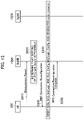
- FIG. 5 is a diagram showing a control sequence (Operation Example 1) of a split bearer when a radio link failure occurs in a secondary cell group.
- FIG. 6 is a diagram showing a configuration example of a split bearer B SP (Split bearer via SCG).
- FIG. 7 is a diagram showing a configuration example (after partial release of the resource) of the split bearer B SP (Split bearer via SCG).
- FIG. 8 is a diagram showing a control sequence (Operation Example 2) of the split bearer when a radio link failure occurs in the secondary cell group.
- FIG. 9 is a diagram showing SN related procedure (Operation Example 1) used for notifying deletion of SCG itself when a bearer (SCG related bearer) belonging to the SCG other than the split bearer B SP is not set.
- FIG. 10 is a diagram showing SN related procedure (Operation Example 2) used for notifying deletion of the SCG itself when the bearer (SCG related bearer) belonging to the SCG other than the split bearer B SP is not set.
- FIG. 11 is a diagram showing SN related procedure (Operation Example 3) used for notifying deletion of the SCG itself when the bearer (SCG related bearer) belonging to the SCG other than the split bearer B SP is not set.
- FIG. 12 is a diagram showing SN related procedure (Operation Example 4) used for notifying deletion of the SCG itself when the bearer (SCG related bearer) belonging to the SCG other than the split bearer B SP is not set.
- FIG. 13 is a diagram showing a setting sequence (Operation Example 1) of the split bearer B SP after partial release of the resource on the SCG (split bearer B SP ) side.
- FIG. 14 is a diagram showing a setting sequence (Operation Example 2) of the split bearer B SP after partial release of the resource on the SCG (split bearer B SP ) side.
- FIG. 15 is a diagram showing an example of hardware configuration of the eNB 100 A, the gNB 100 B, and the UE 200 .
- FIG. 1 is an overall schematic configuration diagram of a radio communication system 10 according to the present embodiment.
- the radio communication system 10 is a radio communication system according to Long Term Evolution (LTE) and 5G New Radio (NR).
- the radio communication system 10 includes a core network 20 and a user equipment 200 (hereinafter, “UE 200 ”).
- a radio base station 100 A (hereinafter, “eNB 100 A”) and a radio base station 100 B (hereinafter, “gNB 100 B”) are connected to the core network 20 .
- the core network 20 can be a core network of the LTE system (EPC (Evolved Packet Core)) or a core network of the NR system (NextGen Core, 5GC).
- EPC Evolved Packet Core
- 5GC NextGen Core
- the core network 20 is connected to Serving Gateway 30 (hereinafter, “S-GW 30 ”) and Mobility Management Entity 40 (hereinafter, “MME 40 ”) that are nodes (devices) of the LTE system. Also, User Plane Function 50 (hereinafter, “UPF 50 ”) and Access and Mobility Management Function 60 (hereinafter, “AMF 60 ”) that are nodes (devices) of the NR system are connected to the core network 20 .
- S-GW 30 Serving Gateway 30
- MME 40 Mobility Management Entity 40
- UPF 50 User Plane Function
- AMF 60 Access and Mobility Management Function
- the eNB 100 A is a radio base station (eNB) of the LTE system and the eNB 100 A can constitute a master base station.
- the eNB 100 A may be expressed as LTE MeNB (or simply MeNB) as appropriate.
- the gNB 100 B is a radio base station (gNB) of the NR system and the gNB 100 B can constitute a secondary base station.
- the gNB 100 B may be expressed as NR SgNB (or simply SgNB) as appropriate.
- the eNB 100 A forms a cell C 1 .
- the gNB 100 B forms a cell C 2 .
- the cell C 1 is a macro cell and the cell C 2 is a small cell. That is, the cell C 2 is smaller than the cell C 1 . Note that there can be more than one cell C 1 and more than one cell C 2 .
- the cell C 1 formed by the eNB 100 A constitutes a master cell group (MCG).
- a secondary cell group (SCG) is configured by the cell C 2 formed by the gNB 100 B.
- FIG. 2 shows a protocol stack of the eNB 100 A (LTE MeNB) and the gNB 100 B (NR SgNB).
- the eNB 100 A includes MAC (Medium Access Control) layer (MAC LTE ), RLC (Radio Link Control) layer (RLC LTE ), PDCP (Packet Data Convergence Protocol) layer (PDCP LTE ), and AS (Access Stratum) sublayer, specifically, Service Data Application Protocol layer (SDAP LTE ).
- MAC LTE Medium Access Control
- RLC LTE Radio Link Control
- PDCP Packet Data Convergence Protocol
- AS Access Stratum sublayer
- SDAP LTE Service Data Application Protocol layer
- the gNB 100 B also includes MAC (Medium Access Control) layer (MAC NR ), RLC (Radio Link Control) layer (RLC NR ), PDCP (Packet Data Convergence Protocol) layer (PDCP NR ), and AS (Access Stratum) sublayer, specifically, Service Data Application Protocol layer (SDAP NR ).
- MAC NR Medium Access Control
- RLC NR Radio Link Control
- PDCP Packet Data Convergence Protocol
- AS Access Stratum sublayer
- SDAP NR Service Data Application Protocol layer
- a control plane (C plane) and a user plane (U plane) are set between the core network 20 (EPC) and the eNB 100 A, however, only the U plane is set between the core network 20 (EPC) and the gNB 100 B.
- each of the eNB 100 A and the gNB 100 B has a physical layer below the MAC layer.
- the later-explained RRC (Radio Resource Control) such as RRC Connection Reconfiguration is included in the AS sublayer (SDAP LTE , SDAP NR ).
- the eNB 100 A and the gNB 100 B are connected to the core network 20 (EPC) via S1-U interface.
- the eNB 100 A and the gNB 100 B are connected to each other via an inter-base station interface (hereinafter, “X interface (Xx/Xn)”.
- X interface Xx/Xn
- the X2 interface is a typical inter-base station interface.
- the eNB 100 A has an RLC layer (RLC LTE ) for the X interface and the eNB 100 A is connected to the PDCP layer (PDCP NR ) of the gNB 100 B via this X interface.
- RLC LTE RLC layer
- PDCP NR PDCP layer
- a split bearer B SP (not-shown in FIG. 2 but shown in FIG. 6 or the like) that passes to the secondary cell group (SCG) via the core network 20 and then branches from the secondary cell group to the radio base station (eNB 100 A) included in the master cell group, specifically, Split bearer via SCG, is set.
- Data to be transmitted from the core network 20 to the UE 200 is transmitted to the UE 200 via the split bearer B SP .
- a functional block configuration of the radio communication system 10 will be explained below. Specifically, a functional block configuration of the eNB 100 A and the UE 200 will be explained.
- a functional block configuration of the radio communication system 10 will be explained. Specifically, a functional block configuration of the eNB 100 A and the UE 200 will be explained.
- FIG. 3 is a functional block diagram of the eNB 100 A and the gNB 100 B.
- the eNB 100 A is different from the eNB 100 A in that it is of the NR system, and in the present embodiment, it constitutes the secondary base station.
- the eNB 100 A includes a radio communication unit 110 , a connection control unit 120 , a failure notification receiving unit 130 , and a resource control unit 140 .
- the eNB 100 A provides the function of each layer in the protocol stack shown in FIG. 2 by the function blocks shown in FIG. 3 .
- the function blocks that relate to the present invention are only shown.
- the radio communication unit 110 performs radio communication in accordance with the LTE system. Specifically, the radio communication unit 110 transmits to/receives from the UE 200 a radio signal in accordance with the LTE system. The user data, and the control data are multiplexed in the radio signal.
- the connection control unit 120 controls a connection between the eNB 100 A and the UE 200 and a connection between the eNB 100 A and the gNB 100 B. Specifically, the connection control unit 120 controls the connection with the UE 200 in the RRC layer. In addition, the connection control unit 120 controls the connection with the gNB 100 B via the X interface (Xx/Xn).
- the connection control unit 120 transmits to the UE 200 a connection message (RRC message) for setting the split bearer B SP (see FIG. 6 or the like).
- the connection control unit 120 can transmit to the UE 200 the RRC Connection Reconfiguration that includes an information element (IE) that permits deactivation (deactivate) of the secondary cell group (SCG) under certain condition.
- IE information element
- to deactivate means that the resource used for setting the split bearer B SP is maintained without releasing; however, with regard to the operation of the UE 200 , it means that no uplink signal of the concerned cell is transmitted and monitoring of the PDCCH is also not performed.
- the UE 200 performs downlink quality measurement by using a downlink synchronization/reference signal and the like; however, the measurement period of such measurement is longer than when in the RRC Connected state.
- connection control unit 120 sends a resource change request (Secondary Node Modification Request) to the gNB 100 B (other radio base station) to instruct to release the resource constituting the split bearer B SP of only a predetermined layer and the layers below thereof in the SCG.
- a resource change request Servicedary Node Modification Request
- the connection control unit 120 transmits to the gNB 100 B the Secondary Node Modification Request that instructs to release the resource of the RLC layer and the layers below thereof, that is, to release the RLC NR and the MAC NR (including the physical layer) of the gNB 100 B.
- S-RLF failure notification
- the connection control unit 120 transmits to the gNB 100 B the Secondary Node Modification Request that instructs to release the resource of the RLC layer and the layers below thereof, that is, to release the RLC NR and the MAC NR (including the physical layer) of the gNB 100 B.
- the connection control unit 120 (that is, the gNB 100 B in the present embodiment) can set a split bearer B SP that reuses the released resource.
- the connection control unit 120 (that is, the gNB 100 B in the present embodiment) can set a new split bearer B SP .
- the connection control unit 120 can delete the setting itself of the SCG. Specifically, when the bearer belonging to the SCG other than the split bearer B SP that passes via the SCG (that is, the gNB 100 B) is not set, the connection control unit 120 deletes the configuration of the SCG, or deletes information such as parameters and identifiers of the physical layer and the MAC layer of all the cells included in the SCG.
- the other bearer belonging to the SCG means a bearer set that passes via a node (radio base station) belonging to the SCG, and SCG bearer, SCG split bearer, or MCG split bearer can be mentioned as the examples thereof.
- the parameter included in CellGroupConfig which is a type of the information element (IE) included in the RRC message, is common to the concerned cell group not dependent on the type of bearer, and the connection control unit 120 deletes that parameter.
- the setting itself of the SCG is deleted (may be called “released”).
- the connection control unit 120 can delete the setting of the SCG at the timing of release of the resource constituting the split bearer B SP in the SCG. Note that, instead of deleting the setting of the SCG at the timing of release of the resource, the connection control unit 120 can delete the setting of the SCG at some other timing such as, for example, after receiving RRC Connection Reconfiguration Complete from the UE 200 .
- connection control unit 120 can re-set the SCG when setting the split bearer B SP that reuses the resource released by the resource control unit 140 . Specifically, if the resource constituting the split bearer B SP of the predetermined layer and the layers below thereof (specifically, the RLC layer and the layers below thereof) in the SCG is only released, when setting the split bearer B SP that reuses the released resource, the connection control unit 120 resets the once released SCG.
- connection control unit 120 sets the contents of the parameter included in the CellGroupConfig to the contents corresponding to the split bearer B SP .
- the connection control unit 120 of the LTE MeNB notifies the NR SgNB (other radio base station) to delete the setting itself of the SCG, if the bearer belonging to the SCG other than the split bearer B SP is not set.
- connection control unit 120 of the LTE MeNB can notify to the NR SgNB (other radio base station) to delete the setting itself of the SCG, in an addition procedure (SN addition procedure) of a node included in the SCG, when a bearer belonging to the SCG other than the split bearer B SP is not set.
- NR SgNB other radio base station
- the failure notification receiving unit 130 receives from the UE 200 a radio link failure (RLF) notification that notifies the radio link failure in the master cell group (MCG) and the secondary cell group (SCG).
- RLF radio link failure
- SCG secondary cell group
- the failure notification receiving unit 130 receives from the UE 200 a failure notification (SCG Failure Information) that indicates that the RLF (hereinafter, “S-RLF”) has occurred in the SCG.
- the resource control unit 140 controls the resource in each layer of the protocol stack shown in FIG. 2 . Specifically, the resource control unit 140 controls the resource required in each layer according to a setting state of the master cell group (MCG) and the secondary cell group (SCG).
- MCG master cell group
- SCG secondary cell group
- the resource control unit 140 releases, based on the resource change request (Secondary Node Modification Request) received from the eNB 100 A, the resource constituting the split bearer B SP of the predetermined layer and the layers below thereof (specifically, the RLC layer and the layers below thereof) in the SCG.
- the resource change request Secondary Node Modification Request
- the resource control unit 140 releases only the MAC NR and the RLC NR among the MAC NR , RLC NR , PDCP NR , and SDAP NR (see FIG. 2 ) that constitute the split bearer B SP .
- the resource control unit 140 of the NR SgNB notifies the radio base station to delete the setting itself of the SCG, if the bearer belonging to the SCG other than the split bearer B SP is not set.
- the resource control unit 140 of the NR SgNB can notify to the UE 200 to delete the setting itself of the SCG, in the change procedure (SN initiated SN modification procedure w/o MN involvement) of the node included in the SCG, if the bearer belonging to the SCG other than the split bearer B SP is not set.
- FIG. 4 is a functional block diagram of the UE 200 .
- the UE 200 includes a radio communication unit 210 , a connection control unit 220 , a failure detecting unit 230 , a cell setting unit 240 , and a quality measuring unit 250 .
- the UE 200 provides the function of each layer in the protocol stack shown in FIG. 2 by the function blocks shown in FIG. 4 . In FIG. 4 , only the function blocks that relate to the present invention are shown.
- the radio communication unit 210 performs radio communication according to the LTE system and the NR system. Specifically, the radio communication unit 210 transmits and receives radio signals to and from the eNB 100 A according to the LTE system. The radio communication unit 210 transmits and receives radio signals to and from the gNB 100 B according to the NR system. The radio signal is multiplexed with user data or control data.
- the connection control unit 220 controls a connection between the UE 200 and the eNB 100 A and a connection between the UE 200 and the gNB 100 B. Specifically, the connection control unit 220 controls a connection in the RRC layer based on a connection message (RRC message) transmitted from the eNB 100 A or the gNB 100 B.
- RRC message connection message
- connection control unit 220 performs a connection change processing in the RRC layer based on the RRC Connection Reconfiguration received from the eNB 100 A (or the gNB 100 B).
- the connection control unit 220 transmits to the eNB 100 A (or the gNB 100 B) the RRC Connection Reconfiguration Complete that indicates that the connection change processing has been completed.
- the failure detecting unit 230 detects the radio link failure (RLF) in the master cell group (MCG) and the secondary cell group (SCG).
- RLF radio link failure
- MCG master cell group
- SCG secondary cell group
- the failure detecting unit 230 detects the RLF in the SCG based on a detection condition of the RLF specified in the 3GPP Technical Standard (TS) (for example, TS 36.300 Chapter 10.1.6).
- TS 3GPP Technical Standard
- the cell setting unit 240 performs settings related to a cell of the master cell group (MCG) or a cell of the secondary cell group (SCG) to which the UE 200 can connect. Specifically, the cell setting unit 240 deactivates (deactivates) the SCG in a certain case.
- the cell setting unit 240 deactivates the setting of the cell (cell C 2 in the present embodiment) included in the SCG.
- the cell setting unit 240 deactivates the setting of the cell included in the SCG.
- the cell setting unit 240 stops the quality measurement of the cell (cell C 2 in the present embodiment) included in the SCG.
- the quality measuring unit 250 measures the reception quality of the cells included in the master cell group (MCG) and the secondary cell group (SCG). Specifically, the quality measuring unit 250 measures Reference Signal Received Power (RSRP) and Reference Signal Received Quality (RSRQ) and the like in each of the cells, and transmits a measurement report (Measurement Report) when a predetermined condition (entering condition) is satisfied.
- MCG master cell group
- SCG secondary cell group
- RSRP Reference Signal Received Power
- RSRQ Reference Signal Received Quality
- the quality measuring unit 250 measures, after partially releasing the resource (of the RLC layer and the layers below thereof) constituting the split bearer B SP in the gNB 100 B (NR SgNB), the reception quality in the SCG at a cycle that is longer than that before releasing the resource.
- the operation of the radio communication system 10 will be explained below. Specifically, the operations related to setting and release of the split bearer (Split bearer via SCG) performed by the eNB 100 A (LTE MeNB), the gNB 100 B (NR SgNB), and the UE 200 will be explained.
- the eNB 100 A LTE MeNB
- the gNB 100 B NR SgNB
- the UE 200 will be explained.
- FIG. 5 shows a control sequence (Operation Example 1) of the split bearer when the radio link failure occurs in the secondary cell group.
- FIG. 6 shows a configuration example of the split bearer B SP (Split bearer via SCG).
- the split bearer B SP (thick line) is the Split bearer via SCG that branches from the PDCP NR of the gNB 100 B to the eNB 100 A.
- a thin line indicates a path of a settable bearer (not limited to split bearer) (see 3GPP TR38.804).
- the split bearer B SP that branched to the eNB 100 A provides a logical communication path to the UE 200 that passes via the RLC LTE and the MAC LTE of the eNB 100 A. Also, the split bearer B SP provides a logical communication path to the UE 200 that passes via the RLC NR and the MAC NR of the gNB 100 B.
- the SCG split bearer as shown in FIG. 6 is set.
- the eNB 100 A transmits to the UE 200 the RRC Connection Reconfiguration that requests to set the split bearer B SP (SCG split bearer) (Step S 110 ).
- the split bearer B SP is called as the Split bearer via SCG; however, it will be shown as “SCG split bearer” for the sake of convenience.
- the UE 200 sets the split bearer B SP based on the received RRC Connection Reconfiguration and transmits the RRC Connection Reconfiguration Complete to the eNB 100 A (Steps S 120 and S 130 ).
- the UE 200 detects the RLF (S-RLF) in the SCG and transmits to the eNB 100 A the failure notification (SCG Failure Information) that indicates that the S-RLF has occurred (Steps S 140 and S 150 ).
- S-RLF RLF
- SCG Failure Information SCG Failure Information
- the eNB 100 A transmits the Secondary Node Modification Request (resource change request) to the gNB 100 B based on the received SCG Failure Information (Step S 160 ).
- the gNB 100 B releases RLC-Config, MACmain-Config, and the dedicated radio resource (radio resource) on the SCG side. Specifically, the gNB 100 B releases the resource related to the split bearer B SP of the RLC NR , the MAC NR , and the physical layer (Step S 170 ).
- the gNB 100 B transmits, to the eNB 100 A, Secondary Node Modification Request Acknowledgement that indicates that the resource has been released (Step S 180 ).
- the eNB 100 A Based on the received Secondary Node Modification Request Acknowledgement, the eNB 100 A transmits to the UE 200 the RRC Connection Reconfiguration that requests to change the setting of the split bearer B SP (Step S 190 ).
- the UE 200 deletes SCG link (Leg) constituting the split bearer B SP (SCG split bearer) (Step S 200 ). Specifically, the UE 200 releases the RLC-Config, the MACmain-Config, and the dedicated radio resource (radio resource) of the SCG side constituting the split bearer B SP , that is, the resource related to the split bearer B SP of the RLC NR , the MAC NR , and the physical layer.
- the eNB 100 A deletes the SCG itself, specifically, deletes the configuration of the SCG, if the bearer (SCG related bearer) belonging to the SCG other than the split bearer B SP is not set.
- the bearer belonging to the SCG as mentioned above, the SCG bearer, the SCG split bearer, or the MCG split bearer can be mentioned.
- the frequency of the measurement report (Measurement Report) related to the SCG that the UE 200 must perform is further reduced.
- the UE 200 transmits to the eNB 100 A the RRC Connection Reconfiguration Complete that indicates that the SCG link (Leg) has been deleted (Step S 210 ).
- FIG. 7 shows an example of a configuration of the split bearer B SP (Split bearer via SCG) (after partial release of the resource).
- the split bearer B SP split bearer via SCG (after partial release of the resource).
- the resource of the RLC NR layer and the layers below thereof of the gNB 100 B is released, (the resource that constitutes) the split bearer B SP is released in a route (a route shown with a dotted line in FIG. 7 ) that goes directly from the gNB 100 B to the UE 200 .
- the split bearer B SP is partially released. Accordingly, the UE 200 performs the measurement reporting (Measurement Report) at a cycle that is longer than that when the SCG is active. As a result, the power consumption of the UE 200 is reduced. Also, because the setting itself of the split bearer B SP on the MCG side is maintained, signaling caused by repeated release and setting of the split bearer can be suppressed.
- FIG. 8 shows a control sequence (Operation Example 2) of the split bearer when a radio link failure occurs in the secondary cell group. Mainly the operations that are different from Operation Example 1 will be explained below.
- Steps S 110 to S 160 shown in FIG. 8 are the same as Steps S 110 to S 160 of FIG. 5 .
- the gNB 100 B transmits to the UE 200 the RRC Connection Reconfiguration based on the received Secondary Node Modification Request (Step S 170 A).
- the RRC Connection Reconfiguration instructs to delete the SCG link (Leg) constituting the split bearer B SP (SCG split bearer) and to release the RLC-Config, the MACmain-Config, and the dedicated radio resource (radio resource) on the SCG side.
- the gNB 100 B and the UE 200 perform deletion of the SCG link (Leg) and release of the resource (Step S 180 A).
- the eNB 100 A and the gNB 100 B delete the SCG itself. Specifically, each of the eNB 100 A and the gNB 100 B deletes the configuration of the SCG, or deletes information such as parameters and identifiers of the physical layer and the MAC layer of all the cells included in the SCG.
- the UE 200 transmits to the gNB 100 B the RRC Connection Reconfiguration Complete that indicates that deletion of the SCG link (Leg) and release of the resource was performed (Step S 190 A).
- the gNB 100 B Based on the received RRC Connection Reconfiguration Complete, the gNB 100 B transmits to the eNB 100 A the Secondary Node Modification Request Acknowledgement that indicates that the resource has been released (Step S 200 A).
- the setting information (radioBearerConfig) of the radio bearer information that the bearer set that passes via the gNB 100 B (SN) is not included other than the SN anchored bearer and the SCG is not set implicitly is notified and shared between the eNB 100 A and the gNB 100 B.
- FIG. 9 shows the SN related procedure (Operation Example 1) used for notifying deletion of the SCG itself when a bearer (SCG related bearer) belonging to the SCG other than the split bearer B SP is not set.
- FIG. 9 shows the MN initiated SN modification procedure specified in TS 37.340.
- the eNB 100 A LTE MeNB/MN
- the gNB 100 B NR SgNB/SN
- Steps S 310 and S 320 the gNB 100 B
- the eNB 100 A includes in SgNB Modification Request the SCG Release to indicate that the SCG is not to be set (SCG Configuration).
- SCG Configuration SCG Configuration
- the gNB 100 B recognizes that the SCG itself is deleted (the SCG itself is not set) when the bearer (SCG related bearer) belonging to the SCG other than the split bearer B SP is not set.
- FIG. 10 shows the SN related procedure (Operation Example 2) used for notifying deletion of the SCG itself when a bearer (SCG related bearer) belonging to the SCG other than the split bearer B SP is not set.
- FIG. 10 shows the SN initiated SN modification procedure with MN involvement specified in TS 37.340.
- the gNB 100 B (NR SgNB/SN) takes the lead and performs the setting change of the NR SgNB/SN with the eNB 100 A (Steps S 410 to S 430 ).
- the gNB 100 B includes in SgNB Modification Required the SCG Release to indicate that the SCG is not set (SCG Configuration). As a result, the eNB 100 A recognizes that the SCG itself is to be deleted (the SCG itself is not to be set) when the bearer (SCG related bearer) belonging to the SCG other than the split bearer B SP is not set.
- Steps S 440 to S 500 the procedure according to the SN initiated SN modification procedure with MN involvement is performed (Steps S 440 to S 500 ).
- FIG. 11 shows the SN related procedure (Operation Example 3) used for notifying deletion of the SCG itself when a bearer (SCG related bearer) belonging to the SCG other than the split bearer B SP is not set.
- FIG. 11 shows the SN initiated SN modification procedure w/o MN involvement defined in TS 37.340.
- the gNB 100 B (NR SgNB/SN) performs the setting change of the NR SgNB/SN with the UE 200 without involving the eNB 100 A (Steps S 610 and S 620 ).
- the gNB 100 B includes in NR RRC Connection Reconfiguration the SCG Release to indicate that the SCG is not set (SCG Configuration). In other words, the gNB 100 B directly instructs the UE 200 to delete the SCG itself when the bearer (SCG related bearer) belonging to the SCG other than the split bearer B SP is not set.
- the UE 200 recognizes that the SCG itself is to be deleted (not to set the SCG itself) when a bearer (SCG related bearer) belonging to the SCG other than the split bearer B SP is not set.
- Step S 630 the procedure according to the SN initiated SN modification procedure w/o MN involvement is performed.
- FIG. 12 shows the SN related procedure (Operation Example 4) used for notifying deletion of the SCG itself when a bearer (SCG related bearer) belonging to the SCG other than the split bearer B SP is not set.
- FIG. 12 shows the SN addition procedure defined in TS 37.340.
- the eNB 100 A LTE MeNB/MN
- the gNB 100 B notifies the gNB 100 B to set only the SN anchored bearer (Step S 710 ).
- the gNB 100 B transmits to the UE 200 the RRC Connection Reconfiguration (SN RRC configuration message w/o SCG PHY/MAC configurations) that does not include the physical (PHY)/MAC layer setting of the SCG (Step S 730 ).
- FIG. 13 shows a setting sequence (Operation Example 1) of the split bearer B SP after partial release of the resource on the SCG (split bearer B SP ) side.
- the eNB 100 A LTE MeNB controls the setting of the split bearer B SP .
- the UE 200 periodically transmits the measurement report (Measurement Report) to the eNB 100 A after partially releasing the resource on the SCG (split bearer B SP ) side (Step S 910 ).
- the eNB 100 A determines whether the split bearer in the SCG, specifically, the split bearer B SP (see FIG. 6 ) can be set (Step S 920 ).
- the split bearer B SP can be set in the same SCG (specifically, the NR SgNB) as before the partial release of the resource on the SCG side, or, it may be determined that the split bearer B SP can be set in the SCG that is different from that before the partial release of the resource on the SCG side.
- the eNB 100 A transmits to the UE 200 the RRC Connection Reconfiguration that requests to set the split bearer B SP (Step S 930 ).
- the UE 200 Based on the received RRC Connection Reconfiguration, the UE 200 resets the SCG link (Leg) constituting the split bearer B SP (SCG split bearer) and the RLC-Config, the MACmain-Config, and the dedicated radio resource on the SCG side (Step S 940 ).
- each of the UE 200 , the eNB 100 A, and the gNB 100 B resets the SCG link (Leg) or the like based on the received RRC Connection Reconfiguration and also resets the SCG deleted by the above operation.
- the split bearer B SP is reset. Specifically, only the SCG link (Leg) deleted by the above operation example and the released RLC-Config, the MACmain-Config, and the dedicated radio resource (radio resource) on the SCG side are reset. That is, the other resource (PDCP NR , RLC LTE , and the like) constituting the split bearer B SP are used as they are maintained.
- the UE 200 transmits to the eNB 100 A the RRC Connection Reconfiguration Complete that indicates that the SCG link (Leg) and the resource have been reset, or that the new SCG split bearer has been set (Step S 950 ).
- the split bearer B SP when it is determined that the split bearer B SP can be set in the same SCG as before the partial release of the resource on the SCG side, the split bearer B SP is reset by using the maintained split bearer B SP resource. Therefore, it is possible to reduce the signaling amount while efficiently using the resource.
- FIG. 14 shows a setting sequence (Operation Example 2) of the split bearer B SP after partial release of the resource on the SCG (split bearer B SP ) side.
- the gNB 100 B controls the setting of the split bearer B SP .
- Operation Example 6 The differences between the present operation example and the above-explained Operation Example 6 will be mainly explained below.
- the difference between Operation Example 6 and Operation Example 7 is that the device that controls is the gNB 100 B instead of the eNB 100 A, and the processing content of each step is the same as Operation Example 1.
- Steps S 910 to S 950 in FIG. 13 correspond to Steps S 1010 to S 1050 in FIG. 14 , respectively.
- each of the UE 200 , the eNB 100 A, and the gNB 100 B resets the SCG link (Leg) and the like based on the received RRC Connection Reconfiguration and resets the SCG deleted by the above operation.
- the eNB 100 A when the eNB 100 A receives from the UE 200 the SCG Failure Information (failure notification) that indicates that the radio link failure (S-RLF) has occurred in the SCG, it is possible to transmit to the gNB 100 B the Secondary Node Modification Request (resource change request) to instruct to release only the resource constituting the split bearer B SP of the RLC layer and the layers below thereof in the SCG.
- S-RLF radio link failure
- the gNB 100 B releases the resource constituting the split bearer B SP of the RLC layer and the layers below thereof in the SCG.
- the maintained resource of the layers above the PDCP layer are used as they are, so that it is possible to reduce the signaling amount associated with the release and setting of the split bearer B SP .
- the eNB 100 A (the gNB 100 B and the UE 200 ) deletes the setting itself of the SCG when the bearer belonging to the SCG other than the split bearer B SP is not set.
- the SCG is completely deleted (released), and the frequency of the measurement report (Measurement Report) on the SCG that the UE 200 has to perform is further reduced.
- the deletion of the setting itself of the SCG involves the deletion (release) of the configuration of the SCG, therefore, further reduction of the frequency of the Measurement Report is expected as compared to the SCG deactivation. Accordingly, reduction of the power consumption of the UE 200 can be effectively achieved.
- the radio communication system 10 when setting the split bearer B SP that passes via the SCG, the suppression of the increase in the signaling amount due to the repeated release and setting of the split bearer B SP and the reduction of the power consumption can be achieved at the same time.
- the eNB 100 A can reset the once deleted SCG when setting the split bearer B SP that reuses the released resource.
- the eNB 100 A can delete the setting itself of the SCG in the MN initiated SN modification procedure (see FIG. 9 ). Also, the eNB 100 A can delete the setting itself of the SCG in the SN addition procedure.
- the gNB 100 B can delete the setting itself of the SCG in the SN initiated SN modification procedure with MN involvement or in the SN initiated SN modification procedure with MN involvement.
- the eNB 100 A is a radio base station (eNB) of the LTE system and constitutes a master base station
- the gNB 100 B is a radio base station (gNB) of the NR system and constitutes a secondary base station; however, this configuration can be reversed. That is, the radio base station (gNB) of the NR system can constitute the master base station and the radio base station (eNB) of the LTE system can constitute the secondary base station.
- each functional block can be realized by a desired combination of hardware and/or software.
- Means for realizing each functional block is not particularly limited. That is, each functional block may be realized by one device combined physically and/or logically. Alternatively, two or more devices separated physically and/or logically may be directly and/or indirectly connected (for example, wired and/or wireless) to each other, and each functional block may be realized by these plural devices.
- FIG. 15 is a diagram showing an example of a hardware configuration of these devices. As shown in FIG. 15 , each of these devices can be configured as a computer device including a processor 1001 , a memory 1002 , a storage 1003 , a communication device 1004 , an input device 1005 , an output device 1006 , a bus 1007 , and the like.
- the functional blocks of the devices can be realized by any of hardware elements of the computer device or a desired combination of the hardware elements.
- the processor 1001 for example, operates an operating system to control the entire computer.
- the processor 1001 can be configured with a central processing unit (CPU) including an interface with a peripheral device, a control device, a computing device, a register, and the like.
- CPU central processing unit
- the memory 1002 is a computer readable recording medium and is configured, for example, with at least one of ROM (Read Only Memory), EPROM (Erasable Programmable ROM), EEPROM (Electrically Erasable Programmable ROM), RAM (Random Access Memory), and the like.
- the memory 1002 can be called register, cache, main memory (main memory), and the like.
- the memory 1002 can store therein a computer program (computer program codes), software modules, and the like that can execute the method according to the above embodiments.
- the storage 1003 is a computer readable recording medium.
- Examples of the storage 1003 include an optical disk such as CD-ROM (Compact Disc ROM), a hard disk drive, a flexible disk, a magneto-optical disk (for example, a compact disk, a digital versatile disk, a Blu-ray® disk), a smart card, a flash memory (for example, a card, a stick, a key drive), a Floppy® disk, a magnetic strip, and the like.
- the storage 1003 can be called an auxiliary storage device.
- the recording medium can be, for example, a database including the memory 1002 and/or the storage 1003 , a server, or other appropriate medium.
- the communication device 1004 is hardware (transmission/reception device) capable of performing communication between computers via a wired and/or wireless network.
- the communication device 1004 is also called, for example, a network device, a network controller, a network card, a communication module, and the like.
- the input device 1005 is an input device (for example, a keyboard, a mouse, a microphone, a switch, a button, a sensor, and the like) that accepts input from the outside.
- the output device 1006 is an output device (for example, a display, a speaker, an LED lamp, and the like) that outputs data to the outside. Note that, the input device 1005 and the output device 1006 may be integrated (for example, a touch screen).
- the respective devices such as the processor 1001 and the memory 1002 , are connected to each other with the bus 1007 for communicating information there among.
- the bus 1007 can be constituted by a single bus or can be constituted by separate buses between the devices.
- the manner of notification of information is not limited to the one explained in the embodiments, and the notification may be performed in other manner.
- the notification of information can be performed by physical layer signaling (for example, DCI (Downlink Control Information), UCI (Uplink Control Information)), upper layer signaling (for example, RRC signaling, MAC (Medium Access Control) signaling, notification information (MIB (Master Information Block), SIB (System Information Block)), other signals, or a combination thereof.
- the RRC signaling can be called RRC message
- the RRC signaling can be, for example, RRC Connection Setup message, RRC Connection Reconfiguration message, and the like.
- the input/output information can be stored in a specific location (for example, a memory) or can be managed in a management table.
- the information to be input/output can be overwritten, updated, or added.
- the information can be deleted after outputting.
- the inputted information can be transmitted to another device.
- the specific operations performed by the eNB 100 A can be performed by another network node (device).
- functions of the eNB 100 A can be provided by combining a plurality of other network nodes.
- a channel and/or a symbol can be replaced with a signal (signal) if that is stated.
- the signal can be replaced with a message.
- system and “network” can be used interchangeably.
- the used parameter and the like can be represented by an absolute value, can be expressed as a relative value from a predetermined value, or can be represented by corresponding other information.
- the radio resource can be indicated by an index.
- the eNB 100 A can accommodate one or more (for example, three) cells (also called sectors).
- the entire coverage area of the base station can be divided into a plurality of smaller areas.
- communication service can be provided by abase station subsystem (for example, a small base station for indoor use RRH: Remote Radio Head).
- the term “cell” or “sector” refers to a part or all of the coverage area of a base station and/or a base station subsystem that performs communication service in this coverage.
- base station eNB
- cell refers to a part or all of the coverage area of a base station and/or a base station subsystem that performs communication service in this coverage.
- base station eNB
- cell refers to a part or all of the coverage area of a base station and/or a base station subsystem that performs communication service in this coverage.
- base station eNodeB
- gNB gNodeB
- the UE 200 is called by the persons skilled in the art as a subscriber station, a mobile unit, a subscriber unit, a radio unit, a remote unit, a mobile device, a radio device, a radio communication device, a remote device, a mobile subscriber station, an access terminal, a mobile terminal, a radio terminal, a remote terminal, a handset, a user agent, a mobile client, a client, or with some other suitable term.
- the phrase “based on” does not mean “based only on” unless explicitly stated otherwise. In other words, the phrase “based on” means both “based only on” and “based at least on”.
- any reference to an element using a designation such as “first”, “second”, and the like used in the present specification generally does not limit the amount or order of those elements. Such designations can be used in the present specification as a convenient way to distinguish between two or more elements. Thus, the reference to the first and second elements does not imply that only two elements can be adopted, or that the first element must precede the second element in some or the other manner.
- the present invention when setting the split bearer that passes via the secondary cell group (SCG), the present invention is useful in achieving both the suppression of the increase in the signaling amount due to repeated release and setting of the split bearer and reduction of the power consumption of the user equipment.
Landscapes
- Engineering & Computer Science (AREA)
- Computer Networks & Wireless Communication (AREA)
- Signal Processing (AREA)
- Mobile Radio Communication Systems (AREA)
Abstract
Description
- Non-Patent Document 1: 3GPP TR 38.804 V14.0.0 Section 5.2.1.2 Bearer types for Dual Connectivity between LTE and NR, 3rd Generation Partnership Project; Technical Specification Group Radio Access Network; Study on New Radio Access Technology; Radio Interface Protocol Aspects Release 14), 3GPP, March 2017
- 10 radio communication system
- 20 core network
- 30 S-GW
- 40 MME
- 50 UPF
- 60 AMF
- 100A eNB
- 100B gNB
- 110 radio communication unit
- 120 connection control unit
- 130 failure notification receiving unit
- 140 resource control unit
- 200 UE
- 210 radio communication unit
- 220 connection control unit
- 230 failure detecting unit
- 240 cell setting unit
- 250 quality measuring unit
- 1001 processor
- 1002 memory
- 1003 storage
- 1004 communication device
- 1005 input device
- 1006 output device
- 1007 bus
Claims (7)
Applications Claiming Priority (1)
| Application Number | Priority Date | Filing Date | Title |
|---|---|---|---|
| PCT/JP2017/041118 WO2019097610A1 (en) | 2017-11-15 | 2017-11-15 | Wireless communication system and wireless base station |
Publications (2)
| Publication Number | Publication Date |
|---|---|
| US20200336364A1 US20200336364A1 (en) | 2020-10-22 |
| US11323311B2 true US11323311B2 (en) | 2022-05-03 |
Family
ID=66539436
Family Applications (1)
| Application Number | Title | Priority Date | Filing Date |
|---|---|---|---|
| US16/763,476 Active 2038-01-03 US11323311B2 (en) | 2017-11-15 | 2017-11-15 | Radio communication system and radio base station |
Country Status (6)
| Country | Link |
|---|---|
| US (1) | US11323311B2 (en) |
| EP (1) | EP3713323B1 (en) |
| JP (1) | JP7086989B2 (en) |
| CN (1) | CN111345088B (en) |
| DK (1) | DK3713323T3 (en) |
| WO (1) | WO2019097610A1 (en) |
Families Citing this family (8)
| Publication number | Priority date | Publication date | Assignee | Title |
|---|---|---|---|---|
| KR102466075B1 (en) * | 2018-03-30 | 2022-11-10 | 지티이 코포레이션 | Change secondary communication node |
| GB2574898A (en) * | 2018-06-22 | 2019-12-25 | Nec Corp | Communication system |
| WO2021241412A1 (en) * | 2020-05-26 | 2021-12-02 | 京セラ株式会社 | Method and user equipment |
| JP7416201B2 (en) * | 2020-08-05 | 2024-01-17 | 日本電気株式会社 | Radio access network nodes, user equipment, and methods thereof |
| US20230422309A1 (en) * | 2020-12-30 | 2023-12-28 | Telefonaktiebolaget Lm Ericsson (Publ) | Secondary cell group (scg) activation and deactivation at secondary node (sn) addition |
| WO2022153510A1 (en) * | 2021-01-15 | 2022-07-21 | 株式会社Nttドコモ | Terminal and wireless communication method |
| ES2988029T3 (en) * | 2021-01-25 | 2024-11-19 | Ericsson Telefon Ab L M | Signaling to release a secondary cell group (SCG) configuration |
| CN115190549A (en) * | 2021-04-01 | 2022-10-14 | 维沃移动通信有限公司 | Primary and secondary cell configuration method and device, UE, network side equipment and readable storage medium |
Citations (7)
| Publication number | Priority date | Publication date | Assignee | Title |
|---|---|---|---|---|
| US20150173120A1 (en) * | 2013-12-13 | 2015-06-18 | Sharp Laboratories Of America, Inc. | Systems and methods for multi-connectivity operation |
| US20150215965A1 (en) * | 2014-01-30 | 2015-07-30 | Sharp Laboratories Of America, Inc. | Systems and methods for dual-connectivity operation |
| US20160212753A1 (en) * | 2015-01-21 | 2016-07-21 | Htc Corporation | Device and Method of Handling Communication Operation with Multiple Base Stations |
| US20160219604A1 (en) * | 2014-01-31 | 2016-07-28 | Kyocera Corporation | Communication control method |
| US20170222876A1 (en) * | 2014-08-04 | 2017-08-03 | Samsung Electronics Co., Ltd. | Signaling in dual connectivity mobile communication networks |
| WO2019031505A1 (en) | 2017-08-10 | 2019-02-14 | 株式会社Nttドコモ | Wireless base station and user device |
| EP3606223A1 (en) | 2017-03-23 | 2020-02-05 | NTT DoCoMo, Inc. | Wireless communication system and wireless base station |
Family Cites Families (9)
| Publication number | Priority date | Publication date | Assignee | Title |
|---|---|---|---|---|
| JP6228871B2 (en) * | 2014-03-17 | 2017-11-08 | Kddi株式会社 | COMMUNICATION DEVICE, COMMUNICATION METHOD, AND PROGRAM |
| JP6605448B2 (en) * | 2014-03-18 | 2019-11-13 | シャープ株式会社 | Wireless communication system, terminal device, wireless communication method, and integrated circuit |
| CN106063360B (en) * | 2014-03-28 | 2020-11-03 | 富士通株式会社 | Bearer management apparatus, method and communication system |
| CN105101253B (en) * | 2014-05-09 | 2020-04-24 | 上海诺基亚贝尔股份有限公司 | Method, main base station and user equipment used in dual-connection system |
| JP5852193B1 (en) * | 2014-08-06 | 2016-02-03 | 株式会社Nttドコモ | User equipment |
| JP6353158B2 (en) * | 2014-08-08 | 2018-07-04 | エルジー エレクトロニクス インコーポレイティド | Method and apparatus for reporting service cancellation for double connection in a wireless communication system |
| WO2016035835A1 (en) * | 2014-09-03 | 2016-03-10 | 株式会社Nttドコモ | Base station and data transfer method |
| US10219317B2 (en) * | 2014-09-25 | 2019-02-26 | Lg Electronics Inc. | Method for handling of data transmission and reception for SeNB related bearer release at a user equipment in a dual connectivity system and device therefor |
| US10342066B2 (en) * | 2014-11-07 | 2019-07-02 | Nokia Solutions And Networks Oy | Method and apparatus for dual connectivity management |
-
2017
- 2017-11-15 JP JP2019554098A patent/JP7086989B2/en active Active
- 2017-11-15 EP EP17931920.7A patent/EP3713323B1/en active Active
- 2017-11-15 CN CN201780096840.4A patent/CN111345088B/en active Active
- 2017-11-15 US US16/763,476 patent/US11323311B2/en active Active
- 2017-11-15 WO PCT/JP2017/041118 patent/WO2019097610A1/en not_active Ceased
- 2017-11-15 DK DK17931920.7T patent/DK3713323T3/en active
Patent Citations (8)
| Publication number | Priority date | Publication date | Assignee | Title |
|---|---|---|---|---|
| US20150173120A1 (en) * | 2013-12-13 | 2015-06-18 | Sharp Laboratories Of America, Inc. | Systems and methods for multi-connectivity operation |
| US20150215965A1 (en) * | 2014-01-30 | 2015-07-30 | Sharp Laboratories Of America, Inc. | Systems and methods for dual-connectivity operation |
| US20160219604A1 (en) * | 2014-01-31 | 2016-07-28 | Kyocera Corporation | Communication control method |
| US20170222876A1 (en) * | 2014-08-04 | 2017-08-03 | Samsung Electronics Co., Ltd. | Signaling in dual connectivity mobile communication networks |
| US20160212753A1 (en) * | 2015-01-21 | 2016-07-21 | Htc Corporation | Device and Method of Handling Communication Operation with Multiple Base Stations |
| EP3606223A1 (en) | 2017-03-23 | 2020-02-05 | NTT DoCoMo, Inc. | Wireless communication system and wireless base station |
| WO2019031505A1 (en) | 2017-08-10 | 2019-02-14 | 株式会社Nttドコモ | Wireless base station and user device |
| US20200260494A1 (en) | 2017-08-10 | 2020-08-13 | Ntt Docomo, Inc. | Radio base station and user device |
Non-Patent Citations (10)
| Title |
|---|
| 3GPP TR 38.804 V14.0.0, Release 14; "3rd Generation Partnership Project; Technical Specification Group Radio Access Network; Study on New Radio Access Technology; Radio Interface Protocol Aspects;" Mar. 2017; Sophia Antipolis Valbonne, France (57 pages). |
| 3GPP TSG-RAN WG2 #99; R2-1708016; "UE behaviour in case of SCG RLF when SCG is the configured path;" Ericsson; Aug. 21-25, 2017; Berlin, Germany (3 pages). |
| 3GPP TSG-RAN WG2 Meeting #99; R2-1709658; "Discussion on S-RLF;" NTT DOCOMO, Inc.; Aug. 21-25, 2017 Berlin, Germany (3 pages). |
| Extended European Search Report issued in counterpart European Patent Application No. 17931920.7, dated Jun. 7, 2021 (7 pages). |
| Intel Corporation; "Other Control plane aspects of Unified bearers"; 3GPP TSG-RAN WG2 Meeting #99, R2-1708833 Berlin, Germany; Aug. 21-25, 2017 (2 pages). |
| International Search Report issued in Application No. PCT/JP2017/041118, dated Jan. 30, 2018 (3 pages). |
| NEC; "SCG failure indication from MN to SN"; 3GPP TSG-RAN WG2 NR Ad-Hoc #2, R2-1707377; Qingdao, China; Jun. 27-29, 2017 (4 pages). |
| Office Action in counterpart Japanese Patent Application No. 2019-554098 dated Nov. 9, 2021 (6 pages). |
| Samsung; "Report on [86#28][LTE/DC] RRC Procedure and PDU specification (Samsung)"; 3GPP TSG-RAN2#87 meeting, R2-143451; Dresden, Germany; Aug. 18-22, 2014 (12 pages). |
| Written Opinion issued in International Application No. PCT/JP2017/041118, dated Jan. 30, 2018 (3 pages). |
Also Published As
| Publication number | Publication date |
|---|---|
| WO2019097610A1 (en) | 2019-05-23 |
| DK3713323T3 (en) | 2024-01-22 |
| CN111345088B (en) | 2024-03-08 |
| US20200336364A1 (en) | 2020-10-22 |
| JPWO2019097610A1 (en) | 2020-11-26 |
| JP7086989B2 (en) | 2022-06-20 |
| EP3713323A1 (en) | 2020-09-23 |
| EP3713323A4 (en) | 2021-07-07 |
| EP3713323B1 (en) | 2023-12-20 |
| CN111345088A (en) | 2020-06-26 |
Similar Documents
| Publication | Publication Date | Title |
|---|---|---|
| US11510280B2 (en) | Radio communication system and radio base station | |
| US11323311B2 (en) | Radio communication system and radio base station | |
| RU2668071C1 (en) | Communication optimization method and device | |
| US11323976B2 (en) | Network device and radio communication method | |
| US20200260494A1 (en) | Radio base station and user device | |
| US11102668B2 (en) | User device and measurement report transmitting method | |
| US20200245180A1 (en) | Radio base station and radio communication method | |
| JP7197652B2 (en) | Wireless communication system and user equipment | |
| US20210168670A1 (en) | User equipment and measurement report transmitting method | |
| EP3668267B1 (en) | Radio base station and communication control method | |
| US11265967B2 (en) | User device for setting packet data convergence protocol entity in dual connectivity | |
| US11523454B2 (en) | Radio communication system and radio communication method | |
| EP3755036A1 (en) | User device and wireless communications method | |
| US11825538B2 (en) | Radio communication system and radio base station |
Legal Events
| Date | Code | Title | Description |
|---|---|---|---|
| FEPP | Fee payment procedure |
Free format text: ENTITY STATUS SET TO UNDISCOUNTED (ORIGINAL EVENT CODE: BIG.); ENTITY STATUS OF PATENT OWNER: LARGE ENTITY |
|
| AS | Assignment |
Owner name: NTT DOCOMO, INC., JAPAN Free format text: ASSIGNMENT OF ASSIGNORS INTEREST;ASSIGNORS:TAKAHASHI, HIDEAKI;UCHINO, TOORU;HAPSARI, WURI ANDARMAWANTI;AND OTHERS;REEL/FRAME:052684/0420 Effective date: 20200226 |
|
| STPP | Information on status: patent application and granting procedure in general |
Free format text: APPLICATION DISPATCHED FROM PREEXAM, NOT YET DOCKETED |
|
| STPP | Information on status: patent application and granting procedure in general |
Free format text: DOCKETED NEW CASE - READY FOR EXAMINATION |
|
| STPP | Information on status: patent application and granting procedure in general |
Free format text: NON FINAL ACTION MAILED |
|
| STPP | Information on status: patent application and granting procedure in general |
Free format text: RESPONSE TO NON-FINAL OFFICE ACTION ENTERED AND FORWARDED TO EXAMINER |
|
| STPP | Information on status: patent application and granting procedure in general |
Free format text: NOTICE OF ALLOWANCE MAILED -- APPLICATION RECEIVED IN OFFICE OF PUBLICATIONS |
|
| STPP | Information on status: patent application and granting procedure in general |
Free format text: PUBLICATIONS -- ISSUE FEE PAYMENT VERIFIED |
|
| STCF | Information on status: patent grant |
Free format text: PATENTED CASE |
|
| MAFP | Maintenance fee payment |
Free format text: PAYMENT OF MAINTENANCE FEE, 4TH YEAR, LARGE ENTITY (ORIGINAL EVENT CODE: M1551); ENTITY STATUS OF PATENT OWNER: LARGE ENTITY Year of fee payment: 4 |