US11314184B2 - Image forming apparatus, image forming method, and data recording medium - Google Patents
Image forming apparatus, image forming method, and data recording medium Download PDFInfo
- Publication number
- US11314184B2 US11314184B2 US17/239,810 US202117239810A US11314184B2 US 11314184 B2 US11314184 B2 US 11314184B2 US 202117239810 A US202117239810 A US 202117239810A US 11314184 B2 US11314184 B2 US 11314184B2
- Authority
- US
- United States
- Prior art keywords
- image
- special
- light
- light responsive
- image forming
- Prior art date
- Legal status (The legal status is an assumption and is not a legal conclusion. Google has not performed a legal analysis and makes no representation as to the accuracy of the status listed.)
- Active
Links
Images


Classifications
-
- G—PHYSICS
- G03—PHOTOGRAPHY; CINEMATOGRAPHY; ANALOGOUS TECHNIQUES USING WAVES OTHER THAN OPTICAL WAVES; ELECTROGRAPHY; HOLOGRAPHY
- G03G—ELECTROGRAPHY; ELECTROPHOTOGRAPHY; MAGNETOGRAPHY
- G03G15/00—Apparatus for electrographic processes using a charge pattern
- G03G15/06—Apparatus for electrographic processes using a charge pattern for developing
- G03G15/08—Apparatus for electrographic processes using a charge pattern for developing using a solid developer, e.g. powder developer
- G03G15/0822—Arrangements for preparing, mixing, supplying or dispensing developer
- G03G15/0865—Arrangements for supplying new developer
-
- G—PHYSICS
- G03—PHOTOGRAPHY; CINEMATOGRAPHY; ANALOGOUS TECHNIQUES USING WAVES OTHER THAN OPTICAL WAVES; ELECTROGRAPHY; HOLOGRAPHY
- G03G—ELECTROGRAPHY; ELECTROPHOTOGRAPHY; MAGNETOGRAPHY
- G03G15/00—Apparatus for electrographic processes using a charge pattern
- G03G15/01—Apparatus for electrographic processes using a charge pattern for producing multicoloured copies
- G03G15/0142—Structure of complete machines
- G03G15/0178—Structure of complete machines using more than one reusable electrographic recording member, e.g. one for every monocolour image
- G03G15/0189—Structure of complete machines using more than one reusable electrographic recording member, e.g. one for every monocolour image primary transfer to an intermediate transfer belt
-
- G—PHYSICS
- G03—PHOTOGRAPHY; CINEMATOGRAPHY; ANALOGOUS TECHNIQUES USING WAVES OTHER THAN OPTICAL WAVES; ELECTROGRAPHY; HOLOGRAPHY
- G03G—ELECTROGRAPHY; ELECTROPHOTOGRAPHY; MAGNETOGRAPHY
- G03G15/00—Apparatus for electrographic processes using a charge pattern
- G03G15/20—Apparatus for electrographic processes using a charge pattern for fixing, e.g. by using heat
- G03G15/2003—Apparatus for electrographic processes using a charge pattern for fixing, e.g. by using heat using heat
- G03G15/2007—Apparatus for electrographic processes using a charge pattern for fixing, e.g. by using heat using heat using radiant heat, e.g. infrared lamps, microwave heaters
-
- G—PHYSICS
- G03—PHOTOGRAPHY; CINEMATOGRAPHY; ANALOGOUS TECHNIQUES USING WAVES OTHER THAN OPTICAL WAVES; ELECTROGRAPHY; HOLOGRAPHY
- G03G—ELECTROGRAPHY; ELECTROPHOTOGRAPHY; MAGNETOGRAPHY
- G03G15/00—Apparatus for electrographic processes using a charge pattern
- G03G15/50—Machine control of apparatus for electrographic processes using a charge pattern, e.g. regulating differents parts of the machine, multimode copiers, microprocessor control
- G03G15/5062—Machine control of apparatus for electrographic processes using a charge pattern, e.g. regulating differents parts of the machine, multimode copiers, microprocessor control by measuring the characteristics of an image on the copy material
-
- G—PHYSICS
- G03—PHOTOGRAPHY; CINEMATOGRAPHY; ANALOGOUS TECHNIQUES USING WAVES OTHER THAN OPTICAL WAVES; ELECTROGRAPHY; HOLOGRAPHY
- G03G—ELECTROGRAPHY; ELECTROPHOTOGRAPHY; MAGNETOGRAPHY
- G03G15/00—Apparatus for electrographic processes using a charge pattern
- G03G15/65—Apparatus which relate to the handling of copy material
- G03G15/6582—Special processing for irreversibly adding or changing the sheet copy material characteristics or its appearance, e.g. stamping, annotation printing, punching
- G03G15/6585—Special processing for irreversibly adding or changing the sheet copy material characteristics or its appearance, e.g. stamping, annotation printing, punching by using non-standard toners, e.g. transparent toner, gloss adding devices
-
- G—PHYSICS
- G03—PHOTOGRAPHY; CINEMATOGRAPHY; ANALOGOUS TECHNIQUES USING WAVES OTHER THAN OPTICAL WAVES; ELECTROGRAPHY; HOLOGRAPHY
- G03G—ELECTROGRAPHY; ELECTROPHOTOGRAPHY; MAGNETOGRAPHY
- G03G13/00—Electrographic processes using a charge pattern
- G03G13/01—Electrographic processes using a charge pattern for multicoloured copies
- G03G13/013—Electrographic processes using a charge pattern for multicoloured copies characterised by the developing step, e.g. the properties of the colour developers
- G03G13/0137—Electrographic processes using a charge pattern for multicoloured copies characterised by the developing step, e.g. the properties of the colour developers developing using a step for deposition of security developing composition, e.g. fluorescent colorants, decolorizable colorants or magnetic ink character recognition toners [MICR]
-
- G—PHYSICS
- G03—PHOTOGRAPHY; CINEMATOGRAPHY; ANALOGOUS TECHNIQUES USING WAVES OTHER THAN OPTICAL WAVES; ELECTROGRAPHY; HOLOGRAPHY
- G03G—ELECTROGRAPHY; ELECTROPHOTOGRAPHY; MAGNETOGRAPHY
- G03G2215/00—Apparatus for electrophotographic processes
- G03G2215/00025—Machine control, e.g. regulating different parts of the machine
- G03G2215/00029—Image density detection
- G03G2215/00033—Image density detection on recording member
- G03G2215/00037—Toner image detection
Definitions
- Embodiments of the present disclosure relate to an image forming apparatus, an image forming method, and a data recording medium.
- image forming apparatuses are known that can form a special-light responsive image including a special-light responsive image forming material that reacts to special light other than visible light and a special-light irresponsive image including the special-light responsive image forming material less than the special-light responsive image.
- the above image forming apparatus is known to print a special-light responsive image onto a recording medium using black toner that serves as a special-light responsive image forming material and has infrared light absorption characteristics, and print a concealing layer as a background image of the special-light responsive image, which serves as a prevention image, using an infrared light non-absorbing material that has the same color as that of the special-light responsive image and serves as a special-light irresponsive image forming material.
- a special-light responsive image can be concealed so as to be invisible by printing a concealing layer whose color is same as that of the special-light responsive image as a background image of the special-light responsive image.
- the concealing layer is printed so as not to overlap with the special-light responsive image, the surface of a recording medium onto which an image is to be printed are free from projections or depressions and are smoothly flat.
- Embodiments of the present disclosure described herein provide three methods of forming an image.
- the first method includes forming, on a recording medium, a special-light responsive image that includes an image forming material including a special-light responsive image forming material that reacts to special light other than visible light and a special-light irresponsive image that includes an image forming material including the special-light responsive image forming material.
- the special-light responsive image forming material of the special-light irresponsive image is less than the special-light responsive image forming material of the special-light responsive image, and the special-light irresponsive image is a prevention image that prevents visibility of the special-light responsive image.
- the forming includes forming an overlaid portion in which at least a portion of one of the prevention image and the special-light responsive image is overlaid on top of another one of the prevention image and the special-light responsive image, and density of adherence of the image forming material in the overlaid portion is smaller than density of adherence of the image forming material in a non-overlaid portion in which one of the prevention image and the special-light responsive image is not overlaid on top of another one of the prevention image and the special-light responsive image.
- the second method of forming an image includes forming, on a recording medium, a special-light responsive image that includes an image forming material including a special-light responsive image forming material that reacts to special light other than visible light and a special-light irresponsive image that includes an image forming material including the special-light responsive image forming material.
- the special-light responsive image forming material of the special-light irresponsive image is less than the special-light responsive image forming material of the special-light responsive image
- the special-light irresponsive image is a prevention image that prevents visibility of the special-light responsive image.
- the prevention image and the special-light responsive image are overlaid on top of each other only at an edge face of the prevention image or an area within a prescribed range from the edge face of the prevention image and an edge face of the special-light responsive image or an area within a prescribed range from the edge face of the special-light responsive image.
- the third method includes forming, on a recording medium, a special-light responsive image that includes an image forming material including a special-light responsive image forming material that reacts to special light other than visible light and a special-light irresponsive image that includes an image forming material including the special-light responsive image forming material, forming a mixed image around the special-light responsive image, the mixed image including the special-light responsive image forming material less than the special-light responsive image forming material of the special-light responsive image and more than the special-light responsive image forming material of the special-light irresponsive image, and forming the special-light irresponsive image around the mixed image.
- the special-light responsive image forming material of the special-light irresponsive image is less than the special-light responsive image forming material of the special-light responsive image.
- FIG. 1 is a diagram illustrating a schematic configuration of a printer according to an embodiment of the present disclosure.
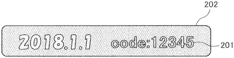
- FIG. 2A is a diagram illustrating how an infrared (IR) image and a jamming image appear when these images are irradiated with infrared light, according to an embodiment of the present disclosure.
- IR infrared
- FIG. 2B is a diagram illustrating how a jamming image appears under visible light, according to an embodiment of the present disclosure.
- FIG. 3A is a sectional view of an IR image and a jamming image when the density of adherence of toner of a jamming image at an overlapping region is equivalent to the density of adherence of toner at the other regions, according to an embodiment of the present disclosure.
- FIG. 3B is a sectional view of an IR image and a jamming image when the density of adherence of toner of the jamming image at an overlapping region is smaller than the density of adherence of toner at the other regions, according to an embodiment of the present disclosure.
- FIG. 4 is a graph illustrating the density of adherence of toner at varying positions of a jamming image, according to an embodiment of the present disclosure.
- FIG. 5 is a sectional view of an IR image and a jamming image, where the density of adherence of toner of both the IR image and the jamming image is reduced at an overlapping region, according to an embodiment of the present disclosure.
- FIG. 6 is a sectional view of an IR image and a jamming image, where an edge face of the jamming image is overlaid with the IR image, according to an embodiment of the present disclosure.
- FIG. 7 is a diagram illustrating an image forming apparatus according to a modification of the above embodiments of the present disclosure.
- FIG. 8 is a diagram illustrating an image forming apparatus according to another modification of the above embodiments of the present disclosure.
- FIG. 9 is a sectional view of the IR image and the jamming image on a mixed image around an IR image where IR toner and normal color toner do not overlap with one another, according to an embodiment of the present disclosure.
- processors may be implemented as program modules or functional processes including routines, programs, objects, components, data structures, etc., that perform particular tasks or implement particular abstract data types and may be implemented using existing hardware at existing network elements or control nodes.
- Such existing hardware may include one or more central processing units (CPUs), digital signal processors (DSPs), application-specific integrated circuits (ASICs), field-programmable gate arrays (FPGAs), computers or the like. These terms may be collectively referred to as processors.
- terms such as “processing” or “computing” or “calculating” or “determining” or “displaying” or the like refer to the action and processes of a computer system, or similar electronic computing device, that manipulates and transforms data represented as physical, electronic quantities within the computer system's registers and memories into other data similarly represented as physical quantities within the computer system memories or registers or other such information storage, transmission or display devices.
- a color printer which serves as an image forming apparatus, to which a method according to an embodiment of the present disclosure is applied is described below with reference to the accompanying drawings.
- Such a color printer according to the present embodiment will be referred to simply as a printer in the following description.
- the apparatus according to an embodiment of the present disclosure is applied to an image forming apparatus with four or less stations.
- the image forming apparatus according to the present embodiment is satisfactory as long as it can form an invisible image onto a recording medium using special toner that forms an invisible image.
- the apparatus according to an embodiment of the present disclosure may be applied not only to a printer but also to a copier alone, facsimile (FAX) alone, or a multifunction peripheral (MFP) that has at least two functions of a printer, a copier, a facsimile, and a scanner.
- FAX facsimile
- MFP multifunction peripheral
- the printer according to the present embodiment uses a special toner to form an invisible image.
- a special toner is used to embed additional information onto a visible image.
- a special toner is used when an invisible image, for example, a textual image such as the image of “COPY” that cannot visually be recognized by human eyes, is to be formed on a recording medium together with a visible image that is formed by color toner.
- an invisible image may also be referred to as, for example, invisible patterns and a ground tint.
- a special toner may be used when a coded image made of a visible image and a coded image made of an invisible image are to be formed on a recording medium in an overlapping manner for the purposes of increasing the amount of information of a coded image such as a bar code image or a quick response (QR) code (registered trademark) image.
- a special toner may be used when only an invisible image is to be formed on a recording medium and no visible image is to be formed.
- an invisible image according to the present embodiment is formed by toner whose transparency is higher than the transparency of normal color toner under visible light, and is made visible as, for example, light emission and color reproduction are performed by the irradiation with infrared light or the like.
- toner that serves as a special-light responsive image forming material
- infrared light absorption toner that has transparency
- fluorescent toner that has transparency and emits fluorescent light when irradiated with ultraviolet (UV) light
- UV ultraviolet
- toner absorbs the light outside the optical range of visible light or emits light within the optical range of visible light in response to the light outside the optical range of visible light is known in the art.
- infrared light absorption toner is used as special toner.
- reference signs are used for some components of the apparatus according to the present embodiment.
- yellow toner, magenta toner, cyan toner, and infrared light absorption toner may be referred to as Y (Y toner), M (M toner), C (C toner), and IR (IR toner), respectively.
- Y toner yellow toner
- M toner M toner
- C C toner
- IR toner IR toner
- clear toner with transparency be used as special toner. The color reproduction of such toner is controlled under visible light. Note also that such clear toner contains a less amount of pigment than normal color toner that serves as special-light irresponsive image forming material.
- a special-light responsive image according to the present embodiment contains a larger amount of infrared light absorber than a special-light irresponsive image per each unit of dimension.
- infrared light absorption toner IR toner
- IR toner infrared light absorption toner
- the transmittance of infrared light of infrared light absorption toner (IR toner) that forms a special-light responsive image according to the present embodiment when a solid image is to be printed is equal to or less than 40%, and the transmittance of infrared light of normal color toner that forms a special-light irresponsive image is equal to or greater than 60%.
- IR toner infrared light absorption toner
- both inorganic materials and organic materials may be used as infrared light absorber that makes up infrared light absorption toner (IR toner).
- infrared light absorber that has transparency and is used to achieve invisibility are under study to implement technologies to embed additional data, and various kinds of materials have been proposed.
- inorganic materials including rare-earth metal such as ytterbium (Yb) and infrared light absorber having copper phosphoric acid crystallized glass are known in the art.
- organic materials including, for example, aluminum compound and croconium pigment are known in the art, and organic materials including infrared light absorber, which have the maximum wavelength for spectral absorption at 750 to 1100 nanometers (nm), have been suggested.
- the absorbance of such organic materials at the wavelength of 650 nanometers (nm) is equal to or smaller than 5% of the absorbance at the maximum wavelength for spectral absorption. Furthermore, the usage of naphthalocyanine pigment has been proposed, and naphthalocyanine pigment is advantageous in difference between the absorbance of visible light and the absorbance of infrared light.
- An infrared light absorber of inorganic materials may be, for example, a glass obtained by adding transition metal ion or a material such as a pigment composed of at least one of inorganic compound and organic compound to a known glass mesh forming material such as phosphoric acid, silica, and boric acid that transmits the light of wavelengths within a visible range, and a crystallized glass obtained by crystallizing the obtained glass with heat treatment.
- a glass obtained by adding transition metal ion or a material such as a pigment composed of at least one of inorganic compound and organic compound to a known glass mesh forming material such as phosphoric acid, silica, and boric acid that transmits the light of wavelengths within a visible range
- a crystallized glass obtained by crystallizing the obtained glass with heat treatment.
- An infrared light absorber of organic materials may be, for example, colored materials such as phthalocyanine compounds and anthraquinone compounds and colorless materials such as aluminum salt compounds and naphthalocyanine compounds.
- colorless materials are preferred. This is because colorless materials do not color the image when the colorless materials are added, and the amount of colorless materials to be added is relatively small as the absorbing power for the range of infrared light is sufficiently large. In most cases, colorless materials do not impair the image quality of the color image.
- naphthalocyanine compounds are preferred from among several kinds of colorless materials. This is because naphthalocyanine compounds have very low absorbance for the range of visible light and are characterized by its absolute colorlessness. Further, naphthalocyanine compounds have little influence on the electrical charge of toner.
- FIG. 1 is a diagram illustrating a schematic configuration of the printer according to the present embodiment.
- the printer according to the present embodiment includes, for example, an image forming unit 1 , a transfer unit 2 , a recording medium supply unit 3 , a fixing device 4 , a recording medium ejection unit 5 , a controller 30 , an image formation controller 40 .
- the image forming unit 1 is provided with four processing units 6 Y, 6 M, 6 C, and 6 IR that serve as a set of image forming units.
- the configuration or structure of the four processing units 6 Y, 6 M, 6 C, and 6 IR is equivalent to each other except that different types of toner are used in each one of the four processing units 6 Y, 6 M, 6 C, and 61 R.
- a processing unit that uses black toner (K) is not provided as a part of the image forming units. Accordingly, a color image or a monochrome image is formed using color toner of Y, M, and C only.
- a processing unit that uses black toner (K) may be added as a part of the image forming units.
- such a configuration could be disadvantageous because size of the apparatus tends to increase.
- the processing unit 61 R that uses IR toner may be configured in a detachable manner, or the printer according to the present embodiment may be configured such that a processing unit that uses K toner may be installed instead of the processing unit that uses the IR toner.
- a processing unit of K toner may be mounted when an image is to be formed without using the IR toner.
- all processing units may be made removable, and the positions at which these processing units are installed may be interchanged with each other.
- the positions of the processing unit that uses IR toner may be interchanged to switch the relative positions of the IR toner image and the multiple color toner image, i.e., the relative positions of the IR toner image and the multiple color toner image in the toner-image stacking direction, on a recording medium on an as-needed basis.
- each one the four processing units 6 Y, 6 M, 6 C, and 61 R includes, for example, a photoconductor 7 that serves as a latent-image bearer and bears a latent image, a charging roller 8 that serves as a charger and evenly charges the surface of the photoconductor 7 , a developing device 9 that serves as a developing unit and develops a latent image on the surface of the photoconductor 7 , and a photoconductor cleaner 10 that serves as a latent-image bearer cleaning unit and cleans the surface of the photoconductor 7 .
- a plurality of exposure devices 11 that serve as latent image forming units and form a latent image on the surfaces of the photoconductors 7 are arranged at positions facing the multiple photoconductors 7 .
- a light-emitting diode (LED) unit is used as the exposure device 11 .
- LED light-emitting diode
- a seamless intermediate transfer belt 12 that serves as an intermediate transferor and is a belt onto which the toner image on the photoconductor 7 is transferred, a plurality of primary transfer rollers 13 that serve as primary transfer units and primarily transfer the image on the photoconductor 7 onto an intermediate transfer belt 12 , a secondary transfer roller 14 that serves as a secondary transfer unit and secondarily transfers the toner image that is transferred to the intermediate transfer belt 12 to the recording medium, and a belt cleaner 17 that serves as an intermediate transferor cleaning unit and cleans the outer circumferential surface of the intermediate transfer belt 12 are arranged.
- the intermediate transfer belt 12 is stretched by a drive roller 15 and at least one driven roller 16 and goes round as the drive roller 15 rotates on the axis.
- the multiple primary transfer rollers 13 are arranged so as to press the intermediate transfer belt 12 against the multiple photoconductors 7 . Due to such a configuration, a plurality of primary transfer nips at which the images on the multiple photoconductors 7 are transferred onto the intermediate transfer belt 12 are formed at a plurality of contact portions where the intermediate transfer belt 12 contacts the multiple photoconductors 7 .
- the secondary transfer roller 14 is arranged so as to contact a portion of the intermediate transfer belt 12 that is wrapped around the drive roller 15 . Due to such a configuration, a secondary transfer nip at which the image on the intermediate transfer belt 12 is transferred onto the recording medium is formed at a contact portion where the intermediate transfer belt 12 contacts the secondary transfer roller 14 through the recording medium.
- a sheet tray 18 that serves as a recording medium storage and stores a sheet of paper P as a recording medium
- a paper feeding roller pair 19 that serves as a recording medium feeding unit and feeds the sheet of paper P from the sheet tray 18
- a timing roller pair 20 that serves as a recording medium conveyance unit and conveys the sheets of paper P that are fed by the paper feeding roller pair 19 to the secondary transfer nip at a prescribed timing
- the recording medium may be, for example, an overhead projector (OHP) sheet, an OHP film, and a fabric in addition to a sheet of paper.
- the sheet of paper may be other various kinds of sheets including, for example, a cardboard, a postcard, an envelope, thin paper, coated paper, art paper, tracing paper, and Japan paper whose surface is uneven and not very smooth.
- a fixing device 21 that serves as a fixing unit and fixes an image onto the sheet of paper P is arranged.
- the fixing device 21 includes, for example, a fixing roller 22 that serves as a fixing unit and is heated by a heat source such as a heater, and a pressure roller 23 that serves as a pressurizer and is pressed against the fixing roller 22 with predetermined level of pressure to form a fixing nip.
- an output roller pair 24 that serves as a recording medium ejection unit and ejects the sheet of paper P that is conveyed through the fixing device 21 to the outside of the apparatus, and an output tray 25 that serves as a recording medium container in which the sheet of paper P ejected through the output roller pair 24 is held are arranged.
- the controller 30 is in charge of the overall control of the printer, and performs image processing on the image data input from, for example, a personal computer (PC) or a reading device such as a scanner.
- the image formation controller 40 controls the image-forming operation performed by each element of the printer such as the image forming unit 1 , the transfer unit 2 , the recording medium supply unit 3 , the fixing device 4 , and the recording medium ejection unit 5 , under control of the controller 30 .
- the printer according to the present embodiment is provided with a plurality of toner cartridges 26 that serve as a granular material container in which a granular material, i.e., toner in the present embodiment, used to form an image is stored.
- Each one of the multiple toner cartridges 26 stores the toner of the color same as the color of the toner inside the corresponding one of the multiple developing devices 9 , and the toner cartridge 26 supplies the developing device 9 with the toner when the amount of the toner inside the corresponding one of the multiple developing devices 9 runs below a predetermined amount.
- the printer according to the present embodiment is provided with a waste-toner container 27 , which serves as another granular material container, in addition to the toner cartridge 26 .
- the waste-toner container 27 stores the waste toner retrieved by the belt cleaner 17 or the photoconductor cleaner 10 .
- the printer according to the present embodiment is provided with a cover 101 used to open and close the upper side of a housing 100 of the image forming apparatus.
- the cover 101 is pivotable in the up-and-down directions around a rotation axis 103 provided for the housing 100 of the image forming apparatus.
- a container holder 102 is arranged in which four toner cartridges 26 can be stored in a removable manner.
- the container holder 102 is pivotable in the up-and-down directions around another rotation axis 104 provided for the housing 100 of the image forming apparatus.
- the processing unit 6 IR that uses IR toner is arranged on the downstream side in the direction of travel of the intermediate transfer belt 12 and the processing units 6 Y, 6 M, and 6 C that use color toner are arranged on the upstream side such that IR toner image composed of IR toner, which may be referred to as a special-toner image, will be formed on the recording medium side compared with the color toner images composed of Y color toner, M color toner, and C color toner.
- the Y toner image, the M toner image, the C toner image, and the IR toner image are stacked on top of each other on the intermediate transfer belt 12 in the order listed from the belt side.
- the IR toner image, the C toner image, the M toner image, and the Y toner image are stacked on top of each other in the order listed from the recording medium side.
- an IR toner image is formed on the recording medium side compared with the color toner images. Due to such a configuration, the IR toner image is hidden by the color toner images as desired, and the visibility of the IR toner image decreases. Moreover, the invisibility of the image formed by IR toner can easily be secured.
- no limitation is indicated thereby, and the relative positions of the IR processing unit 61 R that uses IR toner and the processing units 6 Y, 6 M, and 6 C that use color toner may be adjusted as desired. As described as above, when the positions at which these processing units 6 Y, 6 M, 6 C, and 61 R are installed are configured to be interchangeable with each other, the position of the processing unit that uses IR toner can be changed as desired.
- the multiple photoconductors 7 are driven to rotate, and the surfaces of the photoconductors 7 are evenly charged to a predetermined polarity by the multiple charging rollers 8 .
- the exposure devices 11 irradiate the electrically-conductive surfaces of the multiple photoconductors 7 with laser beams based on the image data input from, for example, a personal computer (PC) or a reading device such as a scanner. Accordingly, an electrostatic latent image is formed.
- PC personal computer
- a reading device such as a scanner.
- the latent image that is formed on each one of the photoconductors 7 is a latent image that is formed based on the single-color image data obtained by separating a desired full-color image into a plurality of color images of Y, M, and C. More specifically, the input image data is converted and decomposed into YCM color data to generate single-color image data using a color conversion and decomposition table with which the color data of the input image, for example, red, green, and blue (RGB) or yellow, cyan, and magenta (YCM), is converted and decomposed into color data (yellow, cyan, or magenta (YCM)) for the printer according to the present embodiment, and the multiple exposure devices 11 that correspond to the yellow, cyan, and magenta (YCM) colors, respectively, form the latent image of each color on the corresponding one of the multiple photoconductors 7 , based on the image data in YCM colors.
- RGB red, green, and blue
- YCM yellow, cyan, and mag
- the infrared (IR) image data is generated based on, for example, the additional information included in the input image data and the additional information added by the printer according to the present embodiment.
- the additional information included in the input image data may be the information added by an application installed onto a personal computer, or may be the information added by the printer driver installed onto a personal computer.
- the exposure device 11 for IR images forms an IR latent image, based on the IR image data, on one of the photoconductors 7 that corresponds to the processing unit 6 IR that uses IR toner.
- the multiple latent image of Y color, C color, M color, or IR that is formed on each one of the photoconductors 7 is supplied with toner from the corresponding one of the developing devices 9 , and is developed as toner image of Y color, C color, M color, or IR.
- the toner images that are formed on the multiple photoconductors 7 are sequentially transferred onto the rotating intermediate transfer belt 12 by superimposing multiple images on top of one another. More specifically, once one of the toner images on the photoconductor 7 is conveyed and reaches the position of the primary transfer nip, the toner images on the multiple photoconductors 7 are sequentially transferred onto the intermediate transfer belt 12 by the transfer electric field formed as a predetermined level of voltage is applied the primary transfer roller 13 .
- a full-color toner image composed of Y color toner, C color toner, and M color toner and an IR toner image (invisible image) composed of IR toner are formed on the surface of the intermediate transfer belt 12 .
- the paper feeding roller 19 starts rotating, and the sheet of paper P is fed from the sheet tray 18 .
- the timing roller pair temporarily halts the sheet P fed through the paper feeding roller pair 19 .
- the timing roller pair 20 starts rotating at a prescribed timing and starts conveying the sheet of paper P to the secondary transfer nip at a timing when the full color toner image formed on the intermediate transfer belt 12 reaches the secondary transfer nip.
- the secondary transfer roller 14 When the sheet of paper P is transferred onto the secondary transfer nip, a predetermined level of voltage is applied the secondary transfer roller 14 . Accordingly, a transfer electric field is formed at the secondary transfer nip, and the toner image on the intermediate transfer belt 12 is transferred onto the sheet P all at once due to the electric field formed at the secondary transfer nip. In so doing, the residual toner that is left on the intermediate transfer belt 12 is removed by the belt cleaner 17 .
- the sheet of paper P is then conveyed to the fixing device 21 , and the toner image is fixed to the sheet of paper P as heated and pressurized by the fixing roller 22 and the pressure roller 23 . Then, the sheet of paper P is ejected to the outside of the apparatus by the output roller pair 24 , and is placed on the output tray 25 .
- the above description relates to an image forming operation when a full-color image is formed on a recording medium.
- an image may be formed using any one of the four processing units 6 Y, 6 M, 6 C, and 61 R.
- an image may be formed using two or three of the four processing units 6 Y, 6 M, 6 C, and 61 R.
- An IR image is not completely colorless but is in pale yellow under visible radiation. For this reason, if the IR image exists on a recording medium on its own, there is some concern that such an IR image could visually be recognized under visible light, and the invisibility of the IR image may not sufficiently be secured.
- FIG. 2A is a diagram illustrating an IR image and a jamming image irradiated with infrared light, according to the present embodiment.
- FIG. 2B is a diagram illustrating a state of a jamming image under visible light, according to the present embodiment.
- a jamming image 202 that serves as a prevention image and prevents the viewability of an IR image 201 under visible light can be formed around the IR image 201 on a recording medium.
- the controller 30 controls the image formation controller 40 to form the jamming image 202 around the IR image 201 in an automatic manner.
- the area of the jamming image 202 may manually be set through the operation of the PC installed with printer driver software.
- the IR image 201 that is formed on the recording medium e.g., “2018.1.1. code: 12345” as illustrated in FIG. 2A , is displayed when manual setting is chosen through the operation of the printer driver software of the PC, and the forming area of the jamming image 202 may manually be specified.
- the jamming image 202 is generated such that its color will be the same as the color of the IR image 201 under visible light, using at least one of the Y color toner, the C color toner, and the M color toner. More specifically, the jamming image 202 is formed such that the difference in gloss value between the IR image 201 and the jamming image 202 will be equal to or smaller than 10% and the color difference ⁇ E between the IR image 201 and that the jamming image 202 will be equal to or smaller than 6.5. Due to such a configuration, as illustrated in FIG. 2B , the IR image 201 is blended into the jamming image 202 , and the IR image 201 cannot visually be recognized easily under visible light.
- the toner of Y color be used. This is because the IR image 201 cannot visually be recognized easily when the image is formed by Y color that is most inconspicuous on a sheet of paper.
- the IR image emits light and reproduces color. As a result, as illustrated in FIG. 2A , the IR image can visually be recognized easily.
- the color difference ⁇ E can be obtained as follows.
- the condition of 2-degree viewing field of the CIE Standard Illuminant D50 that serves as a light source is adopted, and the color of each one of the IR image 201 and the jamming image 202 is measured using a spectrophotometric colorimeter (X-Rite eXact-scan).
- X-Rite eXact-scan a spectrophotometric colorimeter
- the above gloss value is measured and obtained using a glossmeter PG-1, which is produced by Nippon Denshoku Industries, Co. Ltd., at the glancing angle of 60 degrees, according to a method of measuring the gloss value of a specular surface defined in Japanese Industrial Standards (JIS) Z8741.
- JIS Japanese Industrial Standards
- FIG. 3A is a sectional view of the IR image 201 and the jamming image 202 when the density of adherence of toner of the jamming image at an overlapping region 203 is equivalent to the density of adherence of toner at the other regions, according to the present embodiment.
- FIG. 3B is a sectional view of the IR image 201 and the jamming image 202 when the density of adherence of toner of the jamming image 202 at the overlapping region 203 is smaller than the density of adherence of toner at the other regions, according to the present embodiment.
- the jamming image 202 may be displaced from the IR image 201 due to, for example, the decentering of the multiple photoconductors. When such decentering occurs, a bare region may appear in which no toner adheres between the IR image 201 and the jamming image 202 . Under such conditions, there is some concern that an edge face of the IR image 201 may visually be recognized under visible light due to the color difference between the IR image 201 and the white surface of the recording medium at such a bare region. In such cases, the invisibility of the IR image 201 is impaired.
- the jamming image 202 is formed such that the jamming image 202 will overlap with an edge face of the IR image 201 . Due to such a configuration, even if the jamming image 202 is slightly displaced from the IR image 201 , a bare region between the IR image 201 and the jamming image 202 can be prevented. Moreover, an edge face of the IR image 201 can be prevented from being visually recognized under visible light, and the invisibility of the IR image 201 under visible light can be secured as desired.
- the width L of the overlapping region 203 in which the IR image 201 is overlaid with the jamming image 202 is between 50 to 100 ⁇ m.
- the width L of the overlapping region 203 may be equal to or wider than 100 ⁇ m.
- the jamming image 202 may be formed so as to cover the entirety of the IR image 201 .
- the overlapping region 203 in which an edge face of the IR image 201 is overlaid with the jamming image 202 tends to swell by about T1 micrometers ( ⁇ m) compared with the other portions of the image.
- T1 micrometers ⁇ m
- the visible light may be reflected differently between the above overlapping region 203 and its surrounding image area.
- the unevenness at the overlapping region 203 in comparison to the surrounding area is visually recognized, and the IR image 201 is visually recognized due to such unevenness.
- the density of adherence of toner of the jamming image 202 at the overlapping region 203 with the IR image 201 is made smaller than the density of adherence of toner at the other regions. Due to such a configuration, the swelling portion at the overlapping region 203 in which an edge face of the IR image 201 is overlaid with the jamming image 202 can be as small as T2 micrometers ( ⁇ m), and the swelling portion of the overlapping region 203 can be reduced. Note that T2 is smaller than T1, and for example, T2 is equal to or smaller than 10 ⁇ m.
- the unevenness at the overlapping region 203 in which an edge face of the IR image 201 is overlaid with the jamming image 202 in comparison to the surrounding area can be prevented from being visually recognized under visible light, and the invisibility of the IR image 201 can be secured as desired.
- FIG. 4 is a graph illustrating the density of adherence of toner at varying positions of the jamming image 202 , according to the present embodiment.
- the density of adherence of toner indicates the density of the toner that is adhered per each unit of dimension, and the measurement unit of mg/cm 2 is adopted in the present embodiment. Note also that the density of adherence of toner may also be regarded as the amount of adhered toner or the mass of the adhered toner per each unit of dimension. In the present disclosure, the density of toner is indicated in which the toner is so thin that the bare region to which no toner adheres can be seen through. For example, the number of layers of stacked toner is one or less.
- the density of adherence of toner can be obtained as follows. Firstly, a magnified image with the power of two-hundred times is obtained using an optical electron microscope, and the magnified image is binarized. Then, the ratio of the number of pixels of the toner-adhered region to the number of all the pixels is calculated based on the magnified and binarized image.
- the density of adherence of toner of the jamming image 202 at an overlapping region 203 is gradually reduced toward an edge face of the prevention image 202 .
- the density of adherence of toner of the jamming image 202 starts to be reduced from a position B as illustrated in FIG. 4 , which is slightly outside and away from the overlapping region 203 .
- the swelling portion at an edge face A of the IR image 201 i.e., the boundary region between the overlapping region 203 and the jamming image 202 , can be reduced due to such a configuration in which the density of adherence of toner of the jamming image 202 starts to be reduced from a position slightly outside and away from the overlapping region 203 , and the unevenness at an edge face of the IR image 201 can be made inconspicuous and less outstanding under visible light.
- the density of adherence of toner can gradually be reduced from the position B toward an edge face of the jamming image 202 .
- the conditions for primary transfer may be changed to cause dust particles intentionally.
- the density of adherence of toner on the jamming image 202 can gradually be reduced from the position B toward an edge face of the jamming image 202 .
- a known error-diffusion method such as dithering may be adopted, and the printing rate is gradually be reduced by image processing from the position B toward an edge face of the jamming image 202 .
- the density of adherence of toner on the jamming image 202 can gradually be reduced from the position B toward an edge face of the jamming image 202 .
- the exposure value may gradually be reduced, and the amount of adhered toner is gradually reduced.
- a method is adopted to reduce the density of adherence of toner on the jamming image 202 in a gradual manner, there is some concern that the relation between the amount of adhered toner and the exposure value changes depending on, for example, the environment. Further, there is some concern that the density of adherence of toner at the overlapping region 203 cannot be changed to a desired density of adherence in a stable manner. In order to stabilize the density of adherence of toner, the image-forming condition needs to be adjusted as follows.
- a sensor that senses the amount of adhered toner is arranged to form a test image of toner at prescribed time intervals, and the amount of toner adhered to the formed test image is detected by the sensor that senses the amount of adhered toner. By so doing, the image-forming condition can be adjusted as desired.
- the dust particles that are caused by transferring process tend to affect the other images that are formed by toner whose color is same as the color of the toner used to form the jamming image 202 .
- the conditions of dust particle may differ due to, for example, the environment, and there is some concern that the density of adherence of toner at the overlapping region 203 cannot be changed to a desired density of adherence in a stable manner.
- the above method in which the density of adherence of toner on the jamming image 202 is gradually reduced by image processing from the position B toward an edge face of the jamming image 202 is desirable because the density of adherence of toner can be reduced to a desired density of adherence in a stable manner compared with cases in which the density of adherence of toner is reduced by manipulating the exposure value or the image-forming conditions such as the conditions for primary transfer.
- FIG. 5 is a sectional view of the IR image 201 and the jamming image 202 , where the density of adherence of toner of both the IR image 201 and the jamming image 202 is reduced at the overlapping region 203 , according to the present embodiment.
- the density of adherence of toner of the IR image 201 at the overlapping region 203 in which the IR image 201 is overlaid with the jamming image 202 around its edge face may be reduced within a range in which the IR image 201 is not affected in any way.
- the density of adherence of toner of both the 1 R image 201 and the jamming image 202 may be reduced at the overlapping region 203 . Due to such a configuration, the swelling portion of the overlapping region 203 can virtually be eliminated, and the invisibility of the IR image 201 under visible light can further be improved.
- FIG. 6 is a sectional view of the 1 R image 201 and the jamming image 202 , where the IR image 201 overlaps with an edge face of the jamming image 202 , according to the present embodiment.
- an edge face of the jamming image 202 may be overlaid with the IR image 201 .
- the processing unit 6 IR that uses IR toner is arranged on the more downstream side than the processing unit 6 Y, 6 M, and 6 C in the direction where the surface of the intermediate transfer belt 12 travels, as illustrated in FIG. 6 , an edge face of the jamming image 202 may be overlaid with the IR image 201 .
- Each kind of image as illustrated in FIG. 5 and FIG. 6 may be defined as follows depending on the amount of IR toner.
- the IR image 201 may be defined as an image with a relatively large amount of IR toner
- the jamming image 202 may be defined as an image with a relatively small amount of IR toner.
- the above overlapping region 203 may be defined as a mixed image with a not very small and not very large amount of IR toner. In other words, the overlapping region 203 contains both IR toner and color toner in a mixed manner.
- FIG. 9 is a sectional view of the IR image 201 and the jamming image 202 on a mixed image around the IR image 201 where IR toner and normal color toner do not overlap with one another, according to the present embodiment.
- the jamming image 202 may be formed so as to cover the entirety of the IR image 201 .
- the density of adherence of toner of the jamming image 202 at an overlapping region 203 with the IR image 201 is reduced. Due to such a configuration, the increment of the amount of toner adhered to the overlapping region can efficiently be controlled.
- the increment of the image density at an overlapping region is also controlled. Due to such a configuration, even if the jamming image 202 is formed so as to cover the entirety of the IR image 201 , it is not likely that a fixation failure occurs or the image density at a portion of the IR image increases
- the jamming image 202 may be formed so as to cover the entirety of the IR image 201 .
- the IR image 201 is formed using clear or transparent IR toner.
- the IR image may be formed using colored IR toner that is visually be recognized easily under visible light.
- K toner that contains carbon black that serves as an infrared light absorber may be used as colored IR toner.
- the IR image 201 is in black
- a black jamming image 202 is formed using Y color toner, M color toner, and C color toner that do not contain any infrared light absorber such as carbon.
- a coloring material may be added to the above clear or transparent IR toner, and the above clear or transparent IR toner may be used as colored IR toner.
- the jamming image 202 whose color is same as the color of the IR image is formed around the colored IR image 201 that is composed of colored IR toner. As a result, the IR image 201 is blended into the jamming image 202 , and the IR image 201 cannot visually be recognized easily.
- FIG. 7 is a diagram illustrating an image forming apparatus according to a modification of the above embodiments of the present disclosure.
- the image forming apparatus according to a modification of the above embodiments of the present disclosure as illustrated in FIG. 7 is provided with a processing unit 6 T that forms an image using clear toner that serves as a special-light irresponsive image forming material and never absorbs infrared light or reproduces color when irradiated with infrared light.
- the processing unit 6 T is arranged on the more downstream side than the processing unit 61 R in the direction where the surface of the intermediate transfer belt 12 travels.
- clear toner may be used to form the jamming image 202 , and the difference in gloss value between the IR image 201 and the jamming image 202 under visible light can further be reduced. As a result, the degree of invisibility of the IR image 201 under visible light can further be increased.
- the difference in gloss value between the IR image 201 and the jamming image 202 cannot be reduced to 10% or less simply by Y color toner, M color toner, and C color toner when the color tone of the IR toner is low under visible light and the amount of non-IR toner to reproduce the color tone tends to be very small in the first place.
- a processing unit 6 T be provided and that the jamming image be formed using clear toner and at least one of Y color toner, M color toner, and C color toner.
- the difference in gloss value between the IR image 201 and the jamming image 202 can be reduced to a value equal to or smaller than 10%, and the color of the jamming image 202 can be made the same as the color of the IR image 201 .
- FIG. 8 is a diagram illustrating an image forming apparatus according to another modification of the above embodiments of the present disclosure.
- the image forming apparatus includes a full-color image forming apparatus 200 and an IR image forming apparatus 300 that forms an IR image.
- the IR image forming apparatus 300 includes an IR processing unit 306 IR that is optionally installed in the full-color image forming apparatus 200 to form the IR image 201 using IR toner, and a jamming processing unit 306 J that forms the jamming image 202 using jamming toner that serves as special-light irresponsive image forming material.
- the color of such jamming toner is same as the color of the IR toner under visible light, and such jamming toner never absorbs infrared light or reproduces color when irradiated with infrared light.
- the jamming toner according to the present embodiment is adjusted such that its color will be same as the color of the IR toner under visible light, using clear toner and at least one of Y color toner, M color toner, C color toner, and K color toner.
- the sheet of paper P on which an image is formed by the full color image forming apparatus 200 is conveyed to the IR image forming apparatus 300 . Then, an IR toner image is formed at a predetermined position of the sheet of paper P, and a jamming toner image is formed around the IR image. Then, the IR toner image and the jamming toner image are fixed onto the sheet of paper P by the fixing device 304 , and the sheet of paper P is ejected to the output tray 301 .
- the fixing condition needs to be determined such that the images other than the jamming image and the IR image will be formed as desired.
- the fixing condition of the fixing device 304 can be determined without regard for the images other than the jamming image and the IR image. For this reason, for example, the fixing condition of the fixing device 304 can optimally be determined such that there will be no difference in gloss value between the jamming image 202 and the IR image 201 .
- the transfer condition in which dust particles are caused by transferring process may be selected when a jamming toner image is to be transferred to a sheet of paper. Even if such a transfer condition is selected, the other images are not affected.
- the processing unit 6 K that uses K color toner needs to be replaced with the processing unit 6 IR that uses IR toner. However, such replacement is no longer necessary in the configuration as illustrated in FIG. 8 and saving in time can be achieved.
- An image forming apparatus forms, on a recording medium, a special-light responsive image such as the IR image 201 including an image forming material including a special-light responsive image forming material such as IR toner that reacts to special light such as infrared light other than visible light and a special-light irresponsive image including the special-light responsive image forming material.
- the special-light irresponsive image is composed of Y, M, and C toner.
- the special-light responsive image forming material of the special-light irresponsive image is less than the special-light responsive image forming material of the special-light responsive image.
- the special-light irresponsive image is used as a prevention image such as the jamming image 202 that prevents visibility of the special-light responsive image, and at least a portion of one of the special-light irresponsive image and the special-light responsive image is overlaid on top of another one of the special-light irresponsive image and the special-light responsive image.
- the density of adherence of the image forming material over the portion where at least one of the prevention image and the special-light responsive image is overlaid on top of the other one of the prevention image and the special-light responsive image is smaller than the density of adherence of the image forming material at a portion where the one of the prevention image and the special-light responsive image is not overlaid on top of the other one of the prevention image and the special-light responsive image.
- a prevention image such as the jamming image 202 is formed so as to be overlaid on top of a special-light responsive image such as the IR image 201 , the appearance of a bare region between the special-light responsive image and the prevention image can be prevented even if the prevention image is slightly displaced from the special-light responsive image when the prevention image is formed over the special-light responsive image. Due to such a configuration according to the first mode of the present disclosure, the special-light responsive image can be blended into the prevention image as desired under visible light, and the visibility of the special-light responsive image can be prevented as desired.
- the density of adherence of the image forming material such as toner at the overlapping region 203 where the at least one of the prevention image and the special-light responsive image is overlaid with the other one of the prevention image and the special-light responsive image is made smaller than the density of adherence of the image forming material such as toner at the overlapping region 203 where the at least one of the prevention image and the special-light responsive image is not overlaid with the other one of the prevention image and the special-light responsive image.
- the swelling portion of the overlapping region of the two images can be reduced. As a result, the visual recognition of a special-light responsive image under visible light due to the unevenness caused by the swelling portion of the overlapping region of the two images can be prevented.
- the swelling level of the overlapping region of the two images with reference to the non-overlapping region is equal to or less than 10 ⁇ m.
- the unevenness at the overlapping region 203 between a special-light responsive image such as the IR image 201 and a prevention image such as the jamming image 202 in comparison to the surrounding area can be prevented from being visually recognized under visible light, and the invisibility of the special-light responsive image can be secured as desired.
- the area in which the density of adherence is small is broader than the area of the portion in which the at least one of the prevention image and the special-light responsive image is overlaid with the other one of the special-light irresponsive image and the special-light responsive image.
- the swelling portion at the boundary region between the overlapping region 203 and a prevention image such as the jamming image 202 can be reduced, and the unevenness at an edge face of a special-light responsive image such as the IR image 201 can be made inconspicuous and less outstanding under visible light.
- the density of adherence of the image forming material over the portion where the at least one of the special-light irresponsive image and the special-light responsive image is overlaid on top of the other one of the special-light irresponsive image and the special-light responsive image is gradually reduced toward an edge face of the one of the special-light irresponsive image and the special-light responsive image.
- the unevenness at the overlapping region 203 between a special-light responsive image such as the IR image 201 and a prevention image such as the jamming image 202 in comparison to the surrounding area can be prevented from being visually recognized under visible light, and the invisibility of the special-light responsive image can be secured as desired.
- the printing rate at the overlapping region 203 where at least one of the special-light responsive image such as the IR image 201 and the prevention image such as the jamming image 202 is overlaid with the other one of the prevention image and the special-light responsive image is made smaller than the printing rate at an region where the at least one of the special-light responsive image such as the IR image 201 and the prevention image such as the jamming image 202 is not overlaid with the other one of the prevention image and the special-light responsive image.
- the density of adherence of, for example, the density of adherence of toner at the overlapping region 203 can be reduced.
- the density of adherence may be reduced by image processing. By so doing, the density of adherence of toner at the overlapping region 203 may be reduced to a desired density of adherence in a stable manner.
- the density of adherence of both the special-light responsive image such as the IR image 201 and the prevention image such as the jamming image 202 is reduced over the overlapping region.
- the swelling portion of the overlapping region 203 can further be reduced, and the visual recognition of a special-light responsive image such as an IR image due to the swelling portion of the overlapping region 203 can further be prevented.
- a prevention image and a special-light responsive image are formed such that these two kinds of images will be overlaid on top of each other only at an edge face of a prevention image such as the jamming image 202 or an area within a prescribed range from the edge face of the prevention image and an edge face of a special-light responsive image such as the IR image 201 or an area within a prescribed range from the edge face of the special-light responsive image. Due to such a configuration according to the seventh mode of the present disclosure, the consumption of toner can be reduced, and the appearance of a bare region between the special-light responsive image and the prevention image can be prevented.
- the density of adherence of an overlapping region in which a special-light responsive image such as the IR image 201 and a prevention image such as the jamming image 202 overlaid on top of each other is gradually reduced toward an edge face of the special-light responsive image
- the density of adherence of the overlapping region in which the special-light responsive image sand the prevention image overlaid on top of each other is gradually reduced toward an edge face of the prevention image
- the swelling portion of the overlapping region 203 can further be reduced, and the visual recognition of a special-light responsive image such as an IR image due to the swelling portion of the overlapping region 203 can further be prevented.
- An image forming apparatus forms, on a recording medium, a special-light responsive image such as the IR image 201 including an image forming material including a special-light responsive image forming material such as IR toner that reacts to special light such as infrared light other than visible light and a special-light irresponsive image including the special-light responsive image forming material.
- the special-light irresponsive image is composed of Y, M, and C toner.
- the special-light responsive image forming material of the special-light irresponsive image is less than the special-light responsive image forming material of the special-light responsive image.
- the special-light irresponsive image is used as a prevention image such as the jamming image 202 that prevents visibility of the special-light responsive image, and the prevention image and the special-light responsive image are formed such that these two kinds of images will be overlaid on top of each other only at an edge face of the prevention image or an area within a prescribed range from the edge face of the prevention image and an edge face of a special-light responsive image or an area within a prescribed range from the edge face of the special-light responsive image.
- the consumption of toner can be reduced, and the appearance of a bare region between the special-light responsive image and the prevention image can be prevented.
- the color difference ⁇ E between a special-light responsive image such as the IR image 201 and a prevention image such as the jamming image 202 under visible light is equal to or smaller than 6.5.
- the color of a prevention image such as the jamming image 202 can be made substantially the same as the color of a special-light responsive image such as an IR image under visible light. Accordingly, the visibility of the special-light responsive image under visible light can be prevented as desired by the jamming image 202 .
- the difference in gloss value between a special-light responsive image such as the IR image 201 and a prevention image such as the jamming image 202 is equal to or smaller than 10%. Due to such a configuration according to the eleventh mode of the present disclosure, as described above in the embodiment of the present disclosure, the visual recognition of the IR image 201 under visible light due to the difference in gloss value between a special-light responsive image such as the IR image 201 and a prevention image such as the jamming image 202 can be prevented.
- the special light is infrared light.
- a special-light responsive image such as an IR image can be read and obtained by performing irradiation with infrared light.
- a method of forming an image comprising: forming, on a recording medium, a special-light responsive image such as the IR image 201 including an image forming material including a special-light responsive image forming material such as IR toner that reacts to special light such as infrared light other than visible light and a special-light irresponsive image including the special-light responsive image forming material.
- the special-light irresponsive image is composed of Y, M, and C toner.
- the special-light responsive image forming material of the special-light irresponsive image is less than the special-light responsive image forming material of the special-light responsive image.
- the special-light irresponsive image is used as a prevention image such as the jamming image 202 that prevents visibility of the special-light responsive image, and at least a portion of one of the special-light irresponsive image and the special-light responsive image is overlaid on top of another one of the special-light irresponsive image and the special-light responsive image.
- the density of adherence of the image forming material over the portion of the one of the special-light irresponsive image and the special-light responsive image is smaller than density of adherence of the image forming material of the one of the special-light irresponsive image and the special-light responsive image at which the special-light irresponsive image and the special-light responsive image are not overlaid on top of one another.
- a method of forming an image comprising: forming, on a recording medium, a special-light responsive image such as the IR image 201 including an image forming material including a special-light responsive image forming material such as IR toner that reacts to special light such as infrared light other than visible light and a special-light irresponsive image including the special-light responsive image forming material.
- the special-light irresponsive image is composed of Y, M, and C toner.
- the special-light responsive image forming material of the special-light irresponsive image is less than the special-light responsive image forming material of the special-light responsive image.
- the special-light irresponsive image is used as a prevention image such as the jamming image 202 that prevents visibility of the special-light responsive image, and the prevention image and the special-light responsive image are formed such that these two kinds of images will be overlaid on top of each other only at an edge face of the prevention image or an area within a prescribed range from the edge face of the prevention image and an edge face of a special-light responsive image or an area within a prescribed range from the edge face of the special-light responsive image.
- a method of forming an image comprising: forming, on a recording medium, a special-light responsive image such as the IR image 201 including an image forming material including a special-light responsive image forming material such as IR toner that reacts to special light such as infrared light other than visible light and a special-light irresponsive image including the special-light responsive image forming material.
- the special-light irresponsive image is composed of Y, M, and C toner.
- the special-light responsive image forming material of the special-light irresponsive image is less than the special-light responsive image forming material of the special-light responsive image.
- the method according to the fifteenth mode of the present disclosure comprises:
- the mixed image including the special-light responsive image forming material less than the special-light responsive image forming material of the special-light responsive image and more than the special-light responsive image forming material of the special-light irresponsive image; and forming the special-light irresponsive image around the mixed image.
- a data recording medium such as the sheet of paper P on which an image is to be formed, the data recording medium comprising at least one of a character, a sign, a code, and an image formed by the method according to any one of the thirteenth mode to the fifteenth mode.
- a data recording medium on which the visibility of the special-light responsive image is prevented as desired can be provided.
- any one of the above-described and other methods of the present disclosure may be embodied in the form of a computer program stored on any kind of storage medium.
- storage media include, but are not limited to, flexible disks, hard disks, optical discs, magneto-optical discs, magnetic tape, nonvolatile memory cards, read only memory (ROM), etc.
- any one of the above-described and other methods of the present disclosure may be implemented by ASICs, prepared by interconnecting an appropriate network of conventional component circuits, or by a combination thereof with one or more conventional general-purpose microprocessors and/or signal processors programmed accordingly.
Landscapes
- Physics & Mathematics (AREA)
- General Physics & Mathematics (AREA)
- Engineering & Computer Science (AREA)
- Microelectronics & Electronic Packaging (AREA)
- Developing Agents For Electrophotography (AREA)
- Color Electrophotography (AREA)
Abstract
Description
forming the special-light irresponsive image around the mixed image.
Claims (20)
Applications Claiming Priority (6)
| Application Number | Priority Date | Filing Date | Title |
|---|---|---|---|
| JPJP2020-082085 | 2020-05-07 | ||
| JP2020082085 | 2020-05-07 | ||
| JP2020-082085 | 2020-05-07 | ||
| JP2020169368A JP7627434B2 (en) | 2020-05-07 | 2020-10-06 | Image forming apparatus, image forming method, and information recording medium |
| JPJP2020-169368 | 2020-10-06 | ||
| JP2020-169368 | 2020-10-06 |
Publications (2)
| Publication Number | Publication Date |
|---|---|
| US20210349410A1 US20210349410A1 (en) | 2021-11-11 |
| US11314184B2 true US11314184B2 (en) | 2022-04-26 |
Family
ID=78412595
Family Applications (1)
| Application Number | Title | Priority Date | Filing Date |
|---|---|---|---|
| US17/239,810 Active US11314184B2 (en) | 2020-05-07 | 2021-04-26 | Image forming apparatus, image forming method, and data recording medium |
Country Status (1)
| Country | Link |
|---|---|
| US (1) | US11314184B2 (en) |
Citations (9)
| Publication number | Priority date | Publication date | Assignee | Title |
|---|---|---|---|---|
| JPH10882A (en) | 1996-06-14 | 1998-01-06 | Tokin Corp | Magnetic card with ir bar code |
| JP2005161792A (en) | 2003-12-05 | 2005-06-23 | Omron Corp | RECORDING MEDIUM, RECORDING MEDIUM ISSUING DEVICE, AND RECORDING MEDIUM READING DEVICE |
| JP2007003944A (en) | 2005-06-24 | 2007-01-11 | Fuji Xerox Co Ltd | Electrophotographic toner set, electrophotographic developer, and image forming method using same |
| JP2012224017A (en) | 2011-04-21 | 2012-11-15 | National Printing Bureau | Halftone dot printed matter, and method of preparing the same |
| JP2013001077A (en) | 2011-06-21 | 2013-01-07 | Kobayashi Create Co Ltd | Optical reading form |
| US20150063865A1 (en) | 2013-08-30 | 2015-03-05 | Yuusuke Furuichi | Toner container, process cartridge, and image forming apparatus |
| JP2015219407A (en) | 2014-05-19 | 2015-12-07 | 株式会社リコー | Image forming apparatus, image forming method, and image forming program |
| US20180267452A1 (en) | 2017-03-17 | 2018-09-20 | Shinji Aoki | Image forming apparatus |
| CN109976121A (en) * | 2017-12-27 | 2019-07-05 | 株式会社理光 | Image forming apparatus and printed matter |
-
2021
- 2021-04-26 US US17/239,810 patent/US11314184B2/en active Active
Patent Citations (9)
| Publication number | Priority date | Publication date | Assignee | Title |
|---|---|---|---|---|
| JPH10882A (en) | 1996-06-14 | 1998-01-06 | Tokin Corp | Magnetic card with ir bar code |
| JP2005161792A (en) | 2003-12-05 | 2005-06-23 | Omron Corp | RECORDING MEDIUM, RECORDING MEDIUM ISSUING DEVICE, AND RECORDING MEDIUM READING DEVICE |
| JP2007003944A (en) | 2005-06-24 | 2007-01-11 | Fuji Xerox Co Ltd | Electrophotographic toner set, electrophotographic developer, and image forming method using same |
| JP2012224017A (en) | 2011-04-21 | 2012-11-15 | National Printing Bureau | Halftone dot printed matter, and method of preparing the same |
| JP2013001077A (en) | 2011-06-21 | 2013-01-07 | Kobayashi Create Co Ltd | Optical reading form |
| US20150063865A1 (en) | 2013-08-30 | 2015-03-05 | Yuusuke Furuichi | Toner container, process cartridge, and image forming apparatus |
| JP2015219407A (en) | 2014-05-19 | 2015-12-07 | 株式会社リコー | Image forming apparatus, image forming method, and image forming program |
| US20180267452A1 (en) | 2017-03-17 | 2018-09-20 | Shinji Aoki | Image forming apparatus |
| CN109976121A (en) * | 2017-12-27 | 2019-07-05 | 株式会社理光 | Image forming apparatus and printed matter |
Also Published As
| Publication number | Publication date |
|---|---|
| US20210349410A1 (en) | 2021-11-11 |
Similar Documents
| Publication | Publication Date | Title |
|---|---|---|
| US7180631B2 (en) | Gloss-imparting device and color image-forming apparatus | |
| US5915144A (en) | Multicolor image forming method | |
| JP5085715B2 (en) | Image forming apparatus, program, and recording medium | |
| WO2012026625A1 (en) | Image forming device | |
| JP2009139561A (en) | Image forming apparatus | |
| US8078075B2 (en) | Image forming apparatus and method to clean stained portion of image forming apparatus | |
| US8488218B2 (en) | Document reading apparatus | |
| US11314184B2 (en) | Image forming apparatus, image forming method, and data recording medium | |
| US20080063421A1 (en) | Image forming apparatus | |
| US20050058465A1 (en) | Image forming apparatus using two or more toners for ordinary paper or OHP sheet | |
| JP2004309721A (en) | Color image forming apparatus | |
| US20080025774A1 (en) | Image forming method and apparatus | |
| JP5866977B2 (en) | Image forming apparatus and image forming system | |
| US11754959B2 (en) | Image forming apparatus and method to form an invisible image and a visible image in a multi-pass simplex manner | |
| JP4207967B2 (en) | Electrophotographic photoreceptor, image forming method, image forming apparatus and process cartridge using the same | |
| JP7545105B2 (en) | Image forming apparatus and image forming method | |
| US7208251B2 (en) | Method for producing image-recorded medium, image forming apparatus and image-recorded medium | |
| JP7627434B2 (en) | Image forming apparatus, image forming method, and information recording medium | |
| JPH11249377A (en) | Image forming method | |
| JP3368130B2 (en) | Image forming apparatus and method of manufacturing intermediate transfer body | |
| KR20070065364A (en) | Electrophotographic image recording apparatus and image processing apparatus | |
| JP2002116631A (en) | Image forming device | |
| US20240019806A1 (en) | Printed material, image forming apparatus, and data acquisition device | |
| JP7596899B2 (en) | Image forming device | |
| US6852457B2 (en) | Image fixing method |
Legal Events
| Date | Code | Title | Description |
|---|---|---|---|
| AS | Assignment |
Owner name: RICOH COMPANY, LTD., JAPAN Free format text: ASSIGNMENT OF ASSIGNORS INTEREST;ASSIGNORS:HASEGAWA, KEI;KUNIMI, KEIJI;TAKEGUCHI, KYOKO;SIGNING DATES FROM 20210406 TO 20210414;REEL/FRAME:056035/0078 |
|
| FEPP | Fee payment procedure |
Free format text: ENTITY STATUS SET TO UNDISCOUNTED (ORIGINAL EVENT CODE: BIG.); ENTITY STATUS OF PATENT OWNER: LARGE ENTITY |
|
| STPP | Information on status: patent application and granting procedure in general |
Free format text: DOCKETED NEW CASE - READY FOR EXAMINATION |
|
| STPP | Information on status: patent application and granting procedure in general |
Free format text: NOTICE OF ALLOWANCE MAILED -- APPLICATION RECEIVED IN OFFICE OF PUBLICATIONS |
|
| STPP | Information on status: patent application and granting procedure in general |
Free format text: PUBLICATIONS -- ISSUE FEE PAYMENT VERIFIED |
|
| STCF | Information on status: patent grant |
Free format text: PATENTED CASE |
|
| FEPP | Fee payment procedure |
Free format text: MAINTENANCE FEE REMINDER MAILED (ORIGINAL EVENT CODE: REM.); ENTITY STATUS OF PATENT OWNER: LARGE ENTITY |