US11310929B2 - Display device - Google Patents
Display device Download PDFInfo
- Publication number
- US11310929B2 US11310929B2 US16/961,658 US201816961658A US11310929B2 US 11310929 B2 US11310929 B2 US 11310929B2 US 201816961658 A US201816961658 A US 201816961658A US 11310929 B2 US11310929 B2 US 11310929B2
- Authority
- US
- United States
- Prior art keywords
- frame
- display module
- disposed
- display device
- partial
- Prior art date
- Legal status (The legal status is an assumption and is not a legal conclusion. Google has not performed a legal analysis and makes no representation as to the accuracy of the status listed.)
- Active
Links
Images


Classifications
-
- G—PHYSICS
- G06—COMPUTING OR CALCULATING; COUNTING
- G06F—ELECTRIC DIGITAL DATA PROCESSING
- G06F1/00—Details not covered by groups G06F3/00 - G06F13/00 and G06F21/00
- G06F1/16—Constructional details or arrangements
- G06F1/1601—Constructional details related to the housing of computer displays, e.g. of CRT monitors, of flat displays
-
- H—ELECTRICITY
- H05—ELECTRIC TECHNIQUES NOT OTHERWISE PROVIDED FOR
- H05K—PRINTED CIRCUITS; CASINGS OR CONSTRUCTIONAL DETAILS OF ELECTRIC APPARATUS; MANUFACTURE OF ASSEMBLAGES OF ELECTRICAL COMPONENTS
- H05K5/00—Casings, cabinets or drawers for electric apparatus
- H05K5/0017—Casings, cabinets or drawers for electric apparatus with operator interface units
-
- H—ELECTRICITY
- H05—ELECTRIC TECHNIQUES NOT OTHERWISE PROVIDED FOR
- H05K—PRINTED CIRCUITS; CASINGS OR CONSTRUCTIONAL DETAILS OF ELECTRIC APPARATUS; MANUFACTURE OF ASSEMBLAGES OF ELECTRICAL COMPONENTS
- H05K5/00—Casings, cabinets or drawers for electric apparatus
- H05K5/02—Details
- H05K5/0217—Mechanical details of casings
-
- H—ELECTRICITY
- H10—SEMICONDUCTOR DEVICES; ELECTRIC SOLID-STATE DEVICES NOT OTHERWISE PROVIDED FOR
- H10K—ORGANIC ELECTRIC SOLID-STATE DEVICES
- H10K71/00—Manufacture or treatment specially adapted for the organic devices covered by this subclass
-
- H—ELECTRICITY
- H10—SEMICONDUCTOR DEVICES; ELECTRIC SOLID-STATE DEVICES NOT OTHERWISE PROVIDED FOR
- H10K—ORGANIC ELECTRIC SOLID-STATE DEVICES
- H10K77/00—Constructional details of devices covered by this subclass and not covered by groups H10K10/80, H10K30/80, H10K50/80 or H10K59/80
- H10K77/10—Substrates, e.g. flexible substrates
- H10K77/111—Flexible substrates
-
- H10P72/30—
-
- H10P72/3202—
-
- H01L51/5237—
-
- H—ELECTRICITY
- H10—SEMICONDUCTOR DEVICES; ELECTRIC SOLID-STATE DEVICES NOT OTHERWISE PROVIDED FOR
- H10K—ORGANIC ELECTRIC SOLID-STATE DEVICES
- H10K50/00—Organic light-emitting devices
- H10K50/80—Constructional details
- H10K50/84—Passivation; Containers; Encapsulations
-
- Y—GENERAL TAGGING OF NEW TECHNOLOGICAL DEVELOPMENTS; GENERAL TAGGING OF CROSS-SECTIONAL TECHNOLOGIES SPANNING OVER SEVERAL SECTIONS OF THE IPC; TECHNICAL SUBJECTS COVERED BY FORMER USPC CROSS-REFERENCE ART COLLECTIONS [XRACs] AND DIGESTS
- Y02—TECHNOLOGIES OR APPLICATIONS FOR MITIGATION OR ADAPTATION AGAINST CLIMATE CHANGE
- Y02E—REDUCTION OF GREENHOUSE GAS [GHG] EMISSIONS, RELATED TO ENERGY GENERATION, TRANSMISSION OR DISTRIBUTION
- Y02E10/00—Energy generation through renewable energy sources
- Y02E10/50—Photovoltaic [PV] energy
- Y02E10/549—Organic PV cells
Definitions
- the present disclosure relates to a display device.
- LCD liquid crystal display device
- PDP plasma display panel
- ELD electroluminescent display
- VFD vacuum fluorescent display
- a display device using an organic light emitting diode has advantages in that it has excellent luminance characteristics and viewing angle characteristics compared to a liquid crystal display device, and can be implemented in an ultra-thin form without requiring a backlight unit.
- the present disclosure aims to solve the above-mentioned problems and other problems.
- the present disclosure aims to provide a display device capable of adjusting a screen angle while sliding along a frame bent in a curved line.
- the present disclosure provides a display device including a display module, a first frame that is disposed to be long along an upper side of the display module and is convexly bent toward a front side of the display module, a second frame that is spaced apart from the first frame in the vertical direction, is disposed to be long along a lower side of the display module, and is convexly bent in the same direction as the first frame, a third frame disposed between one side of the first frame and one side of the second frame, a fourth frame spaced apart from the third frame in the left-right direction and disposed between the other side of the first frame and the other side of the second frame, an upper sliding member mounted movably in the first frame and fixed to the upper side of the display module, and a lower sliding member mounted movably in the second frame and fixed to the lower side of the display module.
- the lower sliding member may include a second sliding member mounted movably in the second frame and a third sliding member mounted movably in the second frame and spaced apart from the second sliding member in the left-right direction.
- the first frame may include a first partial frame convexly bent toward the front side of the display module, a second partial frame disposed on one side of the first partial frame and formed to be long in a straight line to be connected to an upper side of the third frame, and a third partial frame disposed on the other side of the first partial frame and formed to be long in a straight line to be connected to an upper side of the fourth frame.
- the first sliding member may be mounted on the first partial frame and may move within the first partial frame.
- the first frame may be disposed behind the display module, and a central part of the second frame may protrude more than a front surface of the display module.
- a radius of curvature of the first partial frame may be shorter than a radius of curvature of the second frame.
- a center of curvature of the first partial frame may be the same as a center of curvature of the second frame.
- the first sliding member may include an upper mounting member, an upper roller housing disposed at a lower part or a lower end of the upper mounting member, and an upper roller disposed inside the upper roller housing, wherein the upper roller may include a first upper roller in contact with an upper side of the first partial frame, a second upper roller facing or in contact with a lower side of the first partial frame, a third upper roller spaced apart from the first upper roller in the left-right direction and in contact with the upper side of the first partial frame, and a fourth upper roller spaced apart from the second upper roller in the left-right direction and facing or in contact with the lower side of the first partial frame.
- the second and third sliding members may include a lower mounting member, a lower roller housing disposed at a lower part or a lower end of the lower mounting member, and a lower roller disposed inside the lower roller housing, wherein the lower roller may be in contact with an upper side of the second frame.
- the upper sliding member may be coupled to a back surface of the display module, and an adhesive member may be disposed between the back surface of the display module and the upper sliding member.
- the screen angle can be adjusted while sliding along a frame bent in a curved line.
- the user's convenience can be improved by easily adjusting the screen angle of the display panel depending on the user's location.
- the display panel can be stably supported by using a frame bent in a curved line.
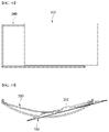
- FIG. 1 is diagrams illustrating an example of a display device according to an embodiment of the present disclosure.
- FIGS. 2 to 5 are diagrams illustrating examples of a frame according to an embodiment of the present disclosure.
- FIGS. 6 to 9 are diagrams illustrating examples of a first sliding member according to an embodiment of the present disclosure.
- FIGS. 10 to 12 are diagrams illustrating examples of second and third sliding members according to an embodiment of the present disclosure.
- FIGS. 13 to 22 are diagrams illustrating an operation of a display device according to an embodiment of the present disclosure.
- FIG. 23 is a diagram illustrating an example of a first sliding member according to another embodiment of the present disclosure.
- first, second, etc. may be used to describe various components, but the components are not limited by such terms. The terms are used only for the purpose of distinguishing one component from other components.
- a singular expression can include a plural expression as long as it does not have an apparently different meaning in context.
- OLED organic light emitting diode display panel
- PDP plasma display panel
- FED field emission display
- LCD liquid crystal panel
- a display device 1000 may include a display module 100 and a frame 200 .
- the display module 100 may include a display panel 110 , a module cover 130 (see FIG. 3 ), and a back cover 150 (see FIG. 3 ).
- the display panel 110 may include a first long side LS 1 , a second long side LS 2 opposite the first long side LS 1 , a first short side SS 1 adjacent to the first long side LS 1 and the second long side LS 2 , and a second short side SS 2 opposite the first short side SS 1 .
- the first short side area SS 1 is referred to as a first side area
- the second short side area SS 2 is referred to as a second side area opposite the first side area
- the first long side area LS 1 is referred to as a third side area adjacent to the first side area and the second side area and positioned between the first side area and the second side area
- the second long side area LS 2 is referred to as a fourth side area adjacent to the first side area and the second side area and positioned between the first side area and the second side area and opposite the third side area.
- first and second long sides LS 1 and LS 2 are longer than lengths of the first and second short sides SS 1 and SS 2
- the lengths of the first and second long sides LS 1 and LS 2 may be approximately equal to the lengths of the first and second short sides SS 1 and SS 2 .
- a first direction X(DR 1 ) may be a direction parallel to the long sides LS 1 and LS 2 of a display panel 110
- a second direction Y(DR 2 ) may be a direction parallel to the short sides SS 1 and SS 2 of the display panel 110
- a third direction DR 3 may be a direction perpendicular to the first direction (X,DR 1 ) and/or the second direction (Y,DR 2 ).
- a side where the display panel 110 of the display device 1000 displays images may be referred to as a front side or a front surface.
- a side where the images cannot be observed may be referred to as a back side or a back surface.
- the first long side LS 1 may be referred to as an upper side or an upper surface.
- the second long side LS 2 may be referred to as a lower side or a lower surface.
- the first short side SS 1 may be referred to as a right side or a right surface
- the second short side SS 2 may be referred to as a left side or a left surface.
- first long side LS 1 , the second long side LS 2 , the first short side SS 1 , and the second short side SS 2 may be referred to as edges of the display panel 110 of the display device 1000 .
- a point at which the first long side LS 1 , the second long side LS 2 , the first short side SS 1 , and the second short side SS 2 meet each other may be referred to as a corner.
- a point where the first long side LS 1 meets the first short side SS 1 may be a first corner C 1
- a point where the second short side SS 2 meets the second long side LS 2 may be a second corner C 2
- a point where the second long side LS 2 meets the first short side SS 1 may be a third corner C 3
- a point where the first long side LS 1 meets the second short side SS 2 may be a fourth corner C 4 .
- a direction from the first short side SS 1 to the second short side SS 2 or a direction from the second short side SS 2 to the first short side SS 1 may be referred to as a left-right direction LR.
- a direction from the first long side LS 1 to the second long side LS 2 or a direction from the second long side LS 2 to the first long side LS 1 may be referred to as an up-down direction UD.
- the display panel 110 may be an organic light emitting diode (OLED) panel.
- OLED organic light emitting diode
- An active matrix type organic light emitting display panel includes an organic light emitting diode (hereinafter referred to as “OLED”) that emits light by itself, and has advantages such as a fast response speed, high light emission efficiency, high brightness, and a wide viewing angle.
- the OLED which is a self-emission device, includes an anode electrode, a cathode electrode, and organic compound layers (HIL, HTL, EML, ETL, EIL) formed therebetween.
- the organic compound layer is formed of a hole injection layer (HIL), a hole transport layer (HTL), an emission layer (EML), an electron transport layer (ETL), and an electron injection layer (EIL).
- HIL hole injection layer
- HTL hole transport layer
- EML emission layer
- ETL electron transport layer
- EIL electron injection layer
- the OLED does not require a separate light source, and the volume and weight of the display device 1000 can be reduced.
- the response speed of the OLED is 1000 times faster than that of the liquid crystal display device, an afterimage may not remain when displaying an image.
- the frame 200 may be disposed below and behind the display module 100 .
- the frame 200 may be mounted on the module cover 130 (see FIG. 3 ) and the back cover 150 (see FIG. 3 ) positioned at a back side of the display panel 110 .
- the frame 200 may be referred to as a stand 200 .
- the frame 200 may be formed to be longer than the first long side LS 1 and the second long side LS 2 of the display panel 100 .
- the display module 100 may include the display panel 110 , the module cover 130 , and the back cover 150 .
- the display panel 110 may be an organic light emitting diode (OLED) panel.
- OLED organic light emitting diode
- the module cover 130 may be disposed on a back surface or a rear surface of the display panel 110 .
- the back cover 130 may be disposed behind the display panel 110 and may be disposed on a back surface or a rear surface of the module cover 130 .
- the frame 200 may be bent in a curved form.
- the frame 200 may be convexly bent toward a front of the display module 100 .
- the frame 200 may include a first frame 210 to a fourth frame 240 .
- the first frame 210 may be disposed around an upper part or upper side of the display module 100 .
- the first frame 210 may be disposed to be long in the left-right direction X corresponding to the first long side LS 1 (see FIG. 1 ) of the display panel 100 .
- the first frame 210 may be formed to be longer than the first long side LS 1 (see FIG. 1 ) of the display module 100 .
- the first frame 210 may be bent in a curved shape.
- the first frame 210 may be referred to as an upper frame, a top frame, a first rail, an upper rail, and a top rail.
- the second frame 220 may be disposed opposite the first frame 210 in the vertical direction Y. An upper part of the second frame 220 may be disposed to face a lower part or a lower side of the display module 100 .
- the second frame 220 may be disposed to be long in the left-right direction X corresponding to the second long side LS 2 (see FIG. 1 ) of the display module 100 .
- the second frame 220 may be formed to be longer than the second long side LS 2 (see FIG. 1 ) of the display module 100 .
- the second frame 220 210 may be bent in a curved shape.
- the second frame 220 may be referred to as a lower frame, a bottom frame, a second rail, a lower rail, and a bottom rail.
- the third frame 230 may be disposed between one side of the first frame 210 and one side of the second frame 220 .
- the one side of the first and second frames 210 and 220 may be referred to as a right side of the first and second frames 210 and 220 .
- the third frame 230 may be disposed to be long in the vertical direction Y corresponding to the first short side SS 1 (see FIG. 1 ) of the display module 100 .
- the third frame 230 may be formed to be substantially the same as or shorter than the first short side SS 1 (see FIG. 1 ) of the display module 100 .
- the third frame 230 may be referred to as a right side frame, a right frame or a supporting frame.
- the fourth frame 240 may be disposed opposite the third frame 230 in the left-right direction X.
- the fourth frame 240 may be disposed between the other side of the first frame 210 and the other side of the second frame 220 .
- the other side of the first and second frames 210 and 220 may be referred to as a left side of the first and second frames 210 and 220 .
- the fourth frame 240 may be disposed to be long in the vertical direction Y corresponding to the second short side SS 2 (see FIG. 1 ) of the display module 100 .
- the fourth frame 240 may be formed to be substantially the same or shorter than the second short side SS 2 (see FIG. 1 ) of the display module 100 .
- the fourth frame 240 may be referred to as a left side frame, a left frame, or a supporting frame.
- Sliding members 310 , 330 , and 350 may be disposed on a back surface or a rear surface and a lower part or a lower surface of the display module 100 .
- the sliding members 310 , 330 , and 350 may be fastened or mounted to the first frame 210 and the second frame 220 .
- the sliding members 310 , 330 , and 350 may be referred to as sliders.
- the sliding members 310 , 330 , and 350 may include a first sliding member 310 to a third sliding member 350 .
- the first sliding member 310 may be disposed between the display module 100 and the first frame 210 .
- the first sliding member 310 may be disposed near or around the first long side LS 1 (see FIG. 1 ) of the display module 100 .
- the first sliding member 310 is fixed to the back surface or the rear surface of the module cover 130 and may be mounted on the first frame 210 .
- the first sliding member 310 may be referred to as an upper sliding member or an upper slider.
- the second sliding member 330 may be disposed to be spaced apart from the first sliding member 310 in the vertical direction Y.
- the second sliding member 330 may be disposed near or around the second long side LS 2 (see FIG. 1 ) of the display module 100 .
- the second sliding member 330 may be disposed between the display module 100 and the second frame 220 .
- the second sliding member 330 may be fixed to the lower surface or a bottom surface of the display module 100 and may be mounted on the second frame 220 .
- the second sliding member 330 may be referred to as a lower sliding member or a lower slider.
- the third sliding member 350 may be disposed to be spaced apart from the first sliding member 310 in the vertical direction Y, and may be disposed to be spaced apart from the second sliding member 330 in the left-right direction X.
- the third sliding member 350 may be disposed near or around the second long side LS 2 (see FIG. 1 ) of the display module 100 .
- the third sliding member 350 may be disposed between the display module 100 and the second frame 220 .
- the third sliding member 350 may be fixed to the lower surface or the bottom surface of the display module 100 and may be mounted on the second frame 220 .
- the third sliding member 350 may be referred to as a lower sliding member or lower slider.
- the display module 100 may be placed or positioned on the second sliding member 330 and the third sliding member 350 which are lower sliding members. Accordingly, the first sliding member 310 may be disposed to be in contact with or face an upper side of the back surface of the display module 100 , and the second and third sliding members 310 , 330 and 350 may be disposed to be in contact with or face the lower surface or the bottom surface of the display module 100 . Since the first sliding member 310 to the third sliding member 350 are disposed on each of the upper and lower sides of the display module 100 together, it is possible to prevent the display module 100 having a thin thickness from being shaken or bent. Accordingly, the first sliding member 310 to the third sliding member 350 are simultaneously disposed on the upper and lower sides of the display module 100 , so that the display module 100 having a relatively thin thickness can be stably supported.
- An adhesive member may be disposed between the sliding members 310 , 330 and 350 and the display module 100 .
- the adhesive member (not shown) may fix or fasten the sliding members 310 , 330 , 350 to the display module 100 .
- the adhesive member (not shown) may include double-sided tape, silicone, or the like.
- a fastening member 201 may connect the first frame 210 to the fourth frame 240 with each other and fix or fasten them.
- the fastening member 201 may include a plurality of connecting members 201 a to 201 d and a plurality of fastening parts S.
- the connecting members 201 a to 201 d may be bent at least once.
- the connecting members 201 a to 201 d may have an alphabetic capital letter “L” shape.
- the fastening part S may penetrate the connecting members 201 a to 201 d to fix the first frame 210 to the fourth frame 240 .
- the fastening portion S may include screws, bolts, washers, and the like.
- the connecting members 201 a to 201 d may include a first connecting member 201 a to a fourth connecting member 201 d.
- the first connecting member 201 a may connect the one side of the first frame 210 and an upper side of the third frame 230 .
- the plurality of fastening parts S may penetrate the first connecting member 201 a being in contact with or facing the one side of the first frame 210 and the upper side of the third frame 230 to fix them.
- the second connecting member 201 b may connect the one side of the second frame 220 and a lower side of the third frame 230 .
- the plurality of fastening parts S may penetrate the second connecting member 201 b being in contact with or facing the one side of the second frame 220 and the lower side of the third frame 230 to fix them.
- the third connecting member 201 c may connect the other side of the second frame 220 and an upper side of the fourth frame 240 .
- the plurality of fastening parts S may penetrate the third connecting member 201 c being in contact with or facing the other side of the second frame 220 and the upper side of the fourth frame 240 to fix them.
- the fourth connecting member 201 d may connect the other side of the second frame 220 and a lower side of the fourth frame 240 .
- the plurality of fastening parts S may penetrate the fourth connecting member 201 d being in contact with or facing the other side of the second frame 220 and the lower side of the fourth frame 240 to fix them.
- the first frame 210 may include a plurality of partial frames 211 , 212 and 213 .
- the first frame 210 may include a first partial frame 211 to a third partial frame 213 .
- the first partial frame 211 may be bent in a curved shape.
- the first sliding member 310 may be mounted on the first partial frame 211 .
- the first sliding member 310 may slide within the first partial frame 211 .
- the second partial frame 212 may be elongated or formed in a straight line.
- the second partial frame 212 may be disposed between the first partial frame 211 and the third frame 230 .
- the second partial frame 212 may connect one side of the first partial frame 211 and the upper side of the third frame 230 .
- the one side of the first partial frame 211 may be referred to as a right side of the first partial frame 211 .
- the third partial frame 213 may be elongated or formed in a straight line.
- the third partial frame 213 may be disposed between the first partial frame 211 and the fourth frame 240 .
- the third partial frame 213 may connect the other side of the first partial frame 211 and the upper side of the fourth frame 240 .
- the other side of the first partial frame 211 may be referred to as a left side of the first partial frame 211 .
- the first partial frame 211 may be disposed between the second partial frame 212 and the third partial frame 213 .
- the first sliding member 310 may be positioned between the second sliding member 330 and the third sliding member 350 .
- the first frame 210 is always disposed at the back B of the display module 100 , but a part of the bent second frame 220 may protrude more toward the front F of the display module 100 than a front surface of the display module 100 .
- the first frame 210 may have a first length L 1
- the second frame 220 may have a second length L 2 .
- the first length L 1 and the second length L 2 may be values measuring lengths protruding from the fourth frame 240 when looking at the display device 1000 from the right side (or left side) to the left side (or right side).
- a third length L 3 may be a value measuring a length spaced from the fourth frame 240 to the back surface or the rear surface of the display panel 100 .
- the first length L 1 may be shorter than the second length L 2 .
- the second length L 2 may be longer than the third length L 3 .
- the third length L 3 may be longer than the first length L 1 and shorter than the second length L 2 .
- the first frame 210 may be disposed at the back B of the display module 100 . Since the second length L 2 is formed to be longer than the third length L 3 , the second frame 220 may further protrude to the front F of the display module 100 .
- the second frame 220 is disposed to face the lower part or lower surface of the display module 100 and is formed to protrude more than the display module 100
- the first frame 210 is disposed on the upper part of display module 100 and is formed to be disposed at the back B of the display module 100 , it is possible to prevent the display module 100 from falling down to the front F.
- the first sliding member 310 may include an upper mounting member 311 , upper rollers 315 , 316 , 317 , and upper roller housings 312 , 313 .
- the upper mounting member 311 may include a central area (a) having a first width W 1 and an outer area (b) having a second width W 2 less than the first width.
- the outer area (b) may extend in the left-right direction X around the central area (a). In other words, the central area (a) of the upper mounting member 311 may protrude toward the back than the outer area (b).
- An adhesive member may fix the central area (a) and the outer area (b) of the upper mounting member 311 to the back or rear surface of the display module 100 .
- the first frame 210 may be disposed below the central area (a) of the upper mounting member 311 .
- the upper mounting member 311 may include a plurality of fastening holes h 1 on the upper part.
- the plurality of fastening holes h 1 may penetrate the upper part of the upper mounting member 311 .
- the upper roller housings 312 and 313 may be disposed at a lower part or a lower end of the upper mounting member 311 . An upper end or an upper part of the upper roller housings 312 and 313 may be open.
- the first frame 210 may penetrate the upper roller housings 312 and 313 in the left-right direction X.
- the upper roller housings 312 and 313 may surround the first frame 210 and may be spaced apart from the first frame 210 at a predetermined interval.
- the upper roller housings 312 and 313 may include a first upper roller housing 312 and a second upper roller housing 313 .
- the first upper roller housing 312 and the second upper roller housing 313 may be disposed adjacent to each other.
- the second upper roller housing 313 may face or be in contact with the first upper roller housing 312 in the left-right direction X.
- the first upper roller housing 312 and the second upper roller housing 313 may include a plurality of roller holes Rh 1 and Rh 2 on side surfaces.
- the plurality of roller holes Rh 1 and Rh 2 may penetrate the side surfaces of the first and second upper roller housings 312 and 313 .
- the upper roller housings 312 and 313 may include a plurality of fastening grooves h 2 on an upper part.
- the fastening groove h 2 may correspond to the fastening hole h 1 .
- a fastening member (not shown) may penetrate the fastening hole h 1 and be inserted into the fastening groove h 1 .
- the fastening member (not shown) may fix the upper mounting member 311 and the upper roller housings 312 and 313 .
- the upper rollers 315 , 316 , and 317 may be disposed inside the upper roller housings 312 , 313 . Both sides of the upper rollers 315 , 316 and 317 may be inserted into the roller holes Rh 1 and Rh 2 disposed on the side surfaces of the first and second upper roller housings 312 and 313 .
- the upper rollers 315 , 316 , 317 may be referred to as upper sliding rollers.
- the upper rollers 315 , 316 , and 317 may include a first upper roller 315 to a fourth upper roller (not shown).
- the first upper roller 315 may be disposed inside the first upper roller housing 312 .
- the first upper roller 315 may be disposed between the central area (a) of the upper mounting member 311 and the first frame 210 .
- the first upper roller 315 may face the central area (a) of the upper mounting member 311 and may be in contact with an upper end or an upper part of the first frame 210 .
- the second upper roller 316 may be spaced apart from the first upper roller 315 in the vertical direction Y to be disposed inside the first upper roller housing 312 .
- the second upper roller 316 may be disposed between a lower part of the first upper roller housing 312 and the first frame 210 .
- the second upper roller 316 may face an inner lower part of the first upper roller housing 312 and may be in contact with a lower end or a lower part of the first frame 210 . Accordingly, the first frame 210 may be disposed between the first upper roller 315 and the second upper roller 316 .
- the third upper roller 317 may be spaced apart from the first upper roller 315 in the left-right direction X to be disposed inside the second upper roller housing 313 .
- the third upper roller 317 may be disposed between the central area (a) of the upper mounting member 311 and the first frame 210 .
- the third upper roller 317 may face the central area (a) of the upper mounting member 311 and may be in contact with the upper end or the upper part of the first frame 210 .
- the fourth upper roller may be spaced apart from the third upper roller 317 in the vertical direction Y to be disposed inside the second upper roller housing 313 .
- the fourth upper roller may be disposed between a lower part of the second upper roller housing 313 and the first frame 210 .
- the fourth upper roller (not shown) may face an inner lower part of the second upper roller housing 313 and may be in contact with the lower end or the lower part of the first frame 210 . Accordingly, the first frame 210 may be disposed between the third upper roller 317 and the fourth upper roller (not shown).
- sliding covers 311 c and 312 c may include a first sliding cover 311 c and a second sliding cover 312 c .
- the first sliding cover 311 c may cover the upper part or upper surface of the upper mounting member 311 .
- the second sliding cover 312 c may cover the first upper roller housing 312 and the second upper roller housing 313 .
- the first sliding member 310 covers the upper mounting member 311 and the upper roller housings 312 and 313 using the first sliding cover 311 c and the second sliding cover 312 c , so that it is possible to prevent dust or foreign matter from entering the upper mounting member 311 and the upper roller housings 312 and 313 .
- the second sliding member 330 may include a lower mounting member 331 , a lower roller 335 and a lower roller housing 333 .
- the lower mounting member 331 may be formed in a shape capable of having a width wider than that of the second frame 220 .
- the lower mounting member 331 may face the lower surface or the bottom surface of the display module 100 .
- An adhesive member (not shown) may fix the lower surface or the bottom surface of the display module 100 placed on the lower mounting member 331 .
- the second frame 220 may be disposed below the display module 100 or the lower mounting member 331 .
- the lower mounting member 331 may include a plurality of fastening holes h 3 on an upper part.
- the plurality of fastening holes h 3 may penetrate the upper part of the lower mounting member 331 .
- the lower roller housing 333 may be disposed on a lower part or a lower end of the lower mounting member 331 .
- the second frame 220 may penetrate the lower roller housing 333 in the left-right direction X.
- the lower roller housing 333 may surround both sides of the second frame 220 , and may be spaced apart from the second frame 220 at a predetermined interval.
- the lower roller housing 333 may include a plurality of fastening grooves h 4 on an upper part.
- the fastening member 201 may penetrate the fastening hole h 3 and be inserted into the fastening groove h 4 .
- the fastening member 201 may fix the lower mounting member 331 and the lower roller housing 333 .
- the plurality of fastening grooves h 4 may be formed in a larger number than the fastening holes h 3 disposed in the lower mounting member 331 .
- the fastening groove h 4 of the lower roller housing 333 is formed more than the fastening hole h 3 of the lower mounting member 331 , a length between the second sliding member 330 and the third sliding member 350 can be easily adjusted depending on the size of the display module 100 . Accordingly, the second sliding member 330 and the third sliding member 350 can more stably sustain or support the display module 100 .
- the lower roller 335 may be disposed inside the lower roller housing 333 .
- the lower roller 335 may be referred to as a lower sliding roller.
- the lower roller 335 may be disposed between the lower mounting member 331 and the second frame 220 .
- the lower roller 335 may face the lower mounting member 331 and may be in contact with an upper end or an upper part of the second frame 220 .
- the second frame 220 may be bent in a curved shape.
- the first partial frame 211 among the first frames 210 may be bent in a curved shape.
- the remaining second and third partial frames 212 and 213 except for the first partial frame 211 may be formed in a straight line.
- the first partial frame 211 may have a first radius of curvature R 1 from a center of curvature C.
- the center of curvature C may be a center of a circle having the first radius of curvature R 1 as the length of the radius.
- the first radius of curvature R 1 may be referred to as a first radius.
- the second frame 220 may have a second radius of curvature R 2 from the center of curvature C.
- the center of curvature C may be the center of a circle having the second radius of curvature R 2 as the length of the radius.
- the second radius of curvature R 2 may be referred to as a second radius.
- the center of curvature C of the first partial frame 211 is the same as the center of curvature C of the second frame 220 .
- the upper rollers 315 , 316 , 317 and the lower roller 335 are disposed in a normal direction of the curvature based on the center of curvature C to easily implement a sliding operation.
- the center of curvature C of the first partial frame 211 is disposed substantially to be the same as the center of curvature C of the second frame 220 , the upper rollers 315 , 316 , 317 of the first sliding member 310 sliding on the first partial frame 211 and the lower roller 335 of the second and third sliding members 330 and 350 sliding on the second frame 220 may operate smoothly along the bent first and second frames 210 and 220 .
- the display device 1000 can move the display module 100 mounted on the bent first frame 210 and the second frame 220 in a curved manner it may freely adjust a screen angle of the display panel 100 depending on the user's location.
- the first radius of curvature R 1 may be less than the second radius of curvature R 2 .
- the second frame 220 may protrude more toward the front of the display module 100 than the first frame 210 .
- the first sliding member 310 may be attached to the back surface of the display module 100 and mounted on the frame 200 .
- the display module 100 may be placed on the second sliding member 330 (see FIG. 13 ) and the third sliding member 350 (see FIG. 13 ) and mounted on the frame.
- all of the first sliding member 310 to the third sliding member 350 are collectively referred to as the sliding member 310 .
- the display module 100 may be basically disposed at the center of the frame 200 .
- the display module 100 may naturally move the display module 100 mounted on the frame 200 to the left along the curved frame 200 along the sliding member 310 .
- FIGS. 17 to 19 illustrate the display module 100 moved to the right at various angles.
- the display module 100 may naturally move the display module 100 mounted on the frame 200 to the left along the curved frame 200 along the sliding member 310 .
- FIGS. 20 to 22 illustrate the display module 100 moved to the left at various angles.
- a first frame 211 a may include a first upper frame 211 a 1 , a second upper frame 211 a 2 , and an upper groove 211 a 3 .
- the first upper frame 211 a 1 may be disposed around the upper part or upper side of the display module 100 .
- the first upper frame 211 a 1 may be disposed to be long in the left-right direction X corresponding to the first long side LS 1 (refer to FIG. 1 ) of the display module 100 .
- the second upper frame 211 a 2 may be disposed to be spaced apart from the first upper frame 211 a 1 in the vertical direction.
- the second upper frame 211 a 2 may be disposed around the upper part or upper side of the display module 100 .
- the second upper frame 211 a 2 may be disposed to be long in the left-right direction X corresponding to the first long side LS 1 (refer to FIG. 1 ) of the display module 100 .
- the upper groove 211 a 3 may be formed concavely between the first upper frame 211 a 1 and the second upper frame 211 a 2 .
- a fourth sliding member 310 a may include an upper mounting member 311 a , an upper roller 313 a , and an upper roller housing 312 a.
- the upper mounting member 311 may be disposed to be long along the first long side LS 1 (see FIG. 1 ) of the display module 100 .
- the upper roller housing 312 a may protrude from the upper mounting member 311 to the back of the display module 100 and may be bent below the display module 100 .
- the upper roller housing 312 a may be spaced apart from the upper part or upper side of the first upper frame 211 a 1 .
- the upper roller 313 a may be disposed inside the upper roller housing 312 a .
- One side of the upper roller 313 a may be fastened to the inner side of the upper roller housing 312 a.
- the upper roller 313 a may be inserted into the upper groove 211 a 3 , face the first upper frame 211 a 1 , and be in contact with the second upper frame 211 a 2 .
- Certain embodiments or other embodiments of the present disclosure described above are not mutually exclusive or distinct from each other.
- the certain embodiments or other embodiments of the present disclosure described above may be used together or combined with each other in configuration or function.
Landscapes
- Engineering & Computer Science (AREA)
- General Engineering & Computer Science (AREA)
- Theoretical Computer Science (AREA)
- Manufacturing & Machinery (AREA)
- Computer Hardware Design (AREA)
- Physics & Mathematics (AREA)
- General Physics & Mathematics (AREA)
- Human Computer Interaction (AREA)
- Microelectronics & Electronic Packaging (AREA)
- Devices For Indicating Variable Information By Combining Individual Elements (AREA)
- Condensed Matter Physics & Semiconductors (AREA)
- Power Engineering (AREA)
Abstract
Description
Claims (13)
Applications Claiming Priority (3)
| Application Number | Priority Date | Filing Date | Title |
|---|---|---|---|
| KR1020180005690A KR102502881B1 (en) | 2018-01-16 | 2018-01-16 | Display device |
| KR10-2018-0005690 | 2018-01-16 | ||
| PCT/KR2018/006730 WO2019142980A1 (en) | 2018-01-16 | 2018-06-14 | Display device |
Publications (2)
| Publication Number | Publication Date |
|---|---|
| US20200367377A1 US20200367377A1 (en) | 2020-11-19 |
| US11310929B2 true US11310929B2 (en) | 2022-04-19 |
Family
ID=67301480
Family Applications (1)
| Application Number | Title | Priority Date | Filing Date |
|---|---|---|---|
| US16/961,658 Active US11310929B2 (en) | 2018-01-16 | 2018-06-14 | Display device |
Country Status (4)
| Country | Link |
|---|---|
| US (1) | US11310929B2 (en) |
| KR (1) | KR102502881B1 (en) |
| DE (1) | DE112018006868B4 (en) |
| WO (1) | WO2019142980A1 (en) |
Families Citing this family (5)
| Publication number | Priority date | Publication date | Assignee | Title |
|---|---|---|---|---|
| KR102807724B1 (en) * | 2020-12-28 | 2025-05-13 | 엘지디스플레이 주식회사 | Display device |
| JP1756097S (en) * | 2022-03-03 | 2023-10-24 | bendable computer screen | |
| JP1756099S (en) * | 2022-03-03 | 2023-10-24 | bendable computer screen | |
| KR102900543B1 (en) * | 2023-02-20 | 2025-12-15 | 엘지전자 주식회사 | Display device |
| CN116293280A (en) * | 2023-04-13 | 2023-06-23 | 深圳市福瑞达显示技术有限公司 | A smart home display screen with fully intelligent angle adjustment and its control method |
Citations (16)
| Publication number | Priority date | Publication date | Assignee | Title |
|---|---|---|---|---|
| US20110222248A1 (en) * | 2008-11-25 | 2011-09-15 | Nec Corporation | Mounting structure of flexible printed circuit board and sliding-type electronic device |
| KR20140141400A (en) | 2013-05-29 | 2014-12-10 | 삼성전자주식회사 | Display apparatus |
| US20150097923A1 (en) * | 2013-10-08 | 2015-04-09 | Samsung Electronics Co., Ltd. | Display apparatus and display method using the same |
| US20150145837A1 (en) * | 2013-11-28 | 2015-05-28 | Samsung Electronics Co., Ltd. | Disply apparatus and method of controlling the same |
| US9116662B1 (en) * | 2014-04-23 | 2015-08-25 | Lg Electronics Inc. | Image display device |
| US20150243194A1 (en) | 2014-02-21 | 2015-08-27 | Educational Equipment Corp. | Display board assembly |
| US20150346537A1 (en) * | 2014-05-26 | 2015-12-03 | Shenzhen China Star Optoelectronics Technology Co. Ltd. | Curved liquid crystal display device |
| KR20150136810A (en) | 2014-05-28 | 2015-12-08 | 삼성전자주식회사 | Display apparatus |
| CN106033654A (en) | 2015-03-11 | 2016-10-19 | 冠捷投资有限公司 | Curved surface display |
| US9843758B2 (en) * | 2013-07-25 | 2017-12-12 | Samsung Electronics Co., Ltd. | Display apparatus and control method for the same |
| US20180220537A1 (en) * | 2017-01-31 | 2018-08-02 | Lg Electronics Inc. | Display device |
| US10165697B2 (en) * | 2016-08-31 | 2018-12-25 | Samsung Electronics Co., Ltd. | Display apparatus |
| US10278300B2 (en) * | 2016-06-28 | 2019-04-30 | Samsung Display Co., Ltd. | Display device |
| US20200212326A1 (en) * | 2018-12-26 | 2020-07-02 | Lg Display Co., Ltd. | Display device |
| US20200278722A1 (en) * | 2019-02-28 | 2020-09-03 | Stand Steady Company, Llc | Attachable display device |
| US10845631B2 (en) * | 2017-08-30 | 2020-11-24 | Lg Display Co., Ltd. | Display device |
Family Cites Families (1)
| Publication number | Priority date | Publication date | Assignee | Title |
|---|---|---|---|---|
| CN104155791B (en) | 2014-07-11 | 2017-01-18 | 京东方科技集团股份有限公司 | Double-sided display panel and double-sided display device |
-
2018
- 2018-01-16 KR KR1020180005690A patent/KR102502881B1/en active Active
- 2018-06-14 DE DE112018006868.4T patent/DE112018006868B4/en active Active
- 2018-06-14 US US16/961,658 patent/US11310929B2/en active Active
- 2018-06-14 WO PCT/KR2018/006730 patent/WO2019142980A1/en not_active Ceased
Patent Citations (19)
| Publication number | Priority date | Publication date | Assignee | Title |
|---|---|---|---|---|
| US20110222248A1 (en) * | 2008-11-25 | 2011-09-15 | Nec Corporation | Mounting structure of flexible printed circuit board and sliding-type electronic device |
| US9560775B2 (en) * | 2013-05-29 | 2017-01-31 | Samsung Electronics Co., Ltd. | Curved display apparatus |
| KR20140141400A (en) | 2013-05-29 | 2014-12-10 | 삼성전자주식회사 | Display apparatus |
| US9843758B2 (en) * | 2013-07-25 | 2017-12-12 | Samsung Electronics Co., Ltd. | Display apparatus and control method for the same |
| US20150097923A1 (en) * | 2013-10-08 | 2015-04-09 | Samsung Electronics Co., Ltd. | Display apparatus and display method using the same |
| KR20150041482A (en) | 2013-10-08 | 2015-04-16 | 삼성전자주식회사 | Display apparatus and display method using the same |
| US20150145837A1 (en) * | 2013-11-28 | 2015-05-28 | Samsung Electronics Co., Ltd. | Disply apparatus and method of controlling the same |
| US9548007B2 (en) * | 2014-02-21 | 2017-01-17 | Educational Equipment Corporation | Display board assembly |
| US20150243194A1 (en) | 2014-02-21 | 2015-08-27 | Educational Equipment Corp. | Display board assembly |
| US9116662B1 (en) * | 2014-04-23 | 2015-08-25 | Lg Electronics Inc. | Image display device |
| US20150346537A1 (en) * | 2014-05-26 | 2015-12-03 | Shenzhen China Star Optoelectronics Technology Co. Ltd. | Curved liquid crystal display device |
| KR20150136810A (en) | 2014-05-28 | 2015-12-08 | 삼성전자주식회사 | Display apparatus |
| CN106033654A (en) | 2015-03-11 | 2016-10-19 | 冠捷投资有限公司 | Curved surface display |
| US10278300B2 (en) * | 2016-06-28 | 2019-04-30 | Samsung Display Co., Ltd. | Display device |
| US10165697B2 (en) * | 2016-08-31 | 2018-12-25 | Samsung Electronics Co., Ltd. | Display apparatus |
| US20180220537A1 (en) * | 2017-01-31 | 2018-08-02 | Lg Electronics Inc. | Display device |
| US10845631B2 (en) * | 2017-08-30 | 2020-11-24 | Lg Display Co., Ltd. | Display device |
| US20200212326A1 (en) * | 2018-12-26 | 2020-07-02 | Lg Display Co., Ltd. | Display device |
| US20200278722A1 (en) * | 2019-02-28 | 2020-09-03 | Stand Steady Company, Llc | Attachable display device |
Non-Patent Citations (1)
| Title |
|---|
| PCT International Application No. PCT/KR2018/006730, International Search Report dated Oct. 15, 2018, 3 pages. |
Also Published As
| Publication number | Publication date |
|---|---|
| WO2019142980A1 (en) | 2019-07-25 |
| US20200367377A1 (en) | 2020-11-19 |
| KR102502881B1 (en) | 2023-02-24 |
| DE112018006868T5 (en) | 2020-10-15 |
| KR20190087198A (en) | 2019-07-24 |
| DE112018006868B4 (en) | 2024-07-11 |
Similar Documents
| Publication | Publication Date | Title |
|---|---|---|
| US11310929B2 (en) | Display device | |
| US10905019B2 (en) | Display device | |
| US12219793B2 (en) | Display device | |
| US10709025B2 (en) | Display device | |
| US10290240B2 (en) | Display device | |
| US9839148B2 (en) | Display device wall mounting apparatus | |
| US20180070467A1 (en) | Display device | |
| US20180184534A1 (en) | Display device | |
| CN107657898B (en) | Display device | |
| KR102557654B1 (en) | Display device | |
| US10656672B2 (en) | Display device | |
| US20170248815A1 (en) | Display device | |
| KR102671605B1 (en) | Display device | |
| US20170347467A1 (en) | Display device | |
| US20230247812A1 (en) | Display device | |
| US8531349B2 (en) | Dual display module and display apparatus having the same | |
| KR102317485B1 (en) | Display device | |
| KR20240095144A (en) | OLED Module and Display Device having the Same | |
| KR102492451B1 (en) | Display apparatus | |
| US20260009452A1 (en) | Display device | |
| US12538442B2 (en) | Display device | |
| US20230337378A1 (en) | Display device |
Legal Events
| Date | Code | Title | Description |
|---|---|---|---|
| FEPP | Fee payment procedure |
Free format text: ENTITY STATUS SET TO UNDISCOUNTED (ORIGINAL EVENT CODE: BIG.); ENTITY STATUS OF PATENT OWNER: LARGE ENTITY |
|
| AS | Assignment |
Owner name: LG ELECTRONICS INC., KOREA, REPUBLIC OF Free format text: ASSIGNMENT OF ASSIGNORS INTEREST;ASSIGNORS:SHO, WEONYOUNG;DO, HONGHAE;IM, SUNGMO;AND OTHERS;REEL/FRAME:053267/0976 Effective date: 20200622 |
|
| STPP | Information on status: patent application and granting procedure in general |
Free format text: DOCKETED NEW CASE - READY FOR EXAMINATION |
|
| STPP | Information on status: patent application and granting procedure in general |
Free format text: NON FINAL ACTION MAILED |
|
| STPP | Information on status: patent application and granting procedure in general |
Free format text: RESPONSE TO NON-FINAL OFFICE ACTION ENTERED AND FORWARDED TO EXAMINER |
|
| STPP | Information on status: patent application and granting procedure in general |
Free format text: NOTICE OF ALLOWANCE MAILED -- APPLICATION RECEIVED IN OFFICE OF PUBLICATIONS |
|
| STPP | Information on status: patent application and granting procedure in general |
Free format text: PUBLICATIONS -- ISSUE FEE PAYMENT VERIFIED |
|
| STCF | Information on status: patent grant |
Free format text: PATENTED CASE |
|
| MAFP | Maintenance fee payment |
Free format text: PAYMENT OF MAINTENANCE FEE, 4TH YEAR, LARGE ENTITY (ORIGINAL EVENT CODE: M1551); ENTITY STATUS OF PATENT OWNER: LARGE ENTITY Year of fee payment: 4 |