US11301007B2 - Portable information device - Google Patents
Portable information device Download PDFInfo
- Publication number
- US11301007B2 US11301007B2 US16/930,491 US202016930491A US11301007B2 US 11301007 B2 US11301007 B2 US 11301007B2 US 202016930491 A US202016930491 A US 202016930491A US 11301007 B2 US11301007 B2 US 11301007B2
- Authority
- US
- United States
- Prior art keywords
- chassis
- sheet
- front side
- cover member
- spine member
- Prior art date
- Legal status (The legal status is an assumption and is not a legal conclusion. Google has not performed a legal analysis and makes no representation as to the accuracy of the status listed.)
- Active, expires
Links
Images


Classifications
-
- G—PHYSICS
- G06—COMPUTING OR CALCULATING; COUNTING
- G06F—ELECTRIC DIGITAL DATA PROCESSING
- G06F1/00—Details not covered by groups G06F3/00 - G06F13/00 and G06F21/00
- G06F1/16—Constructional details or arrangements
- G06F1/1613—Constructional details or arrangements for portable computers
- G06F1/1615—Constructional details or arrangements for portable computers with several enclosures having relative motions, each enclosure supporting at least one I/O or computing function
- G06F1/1616—Constructional details or arrangements for portable computers with several enclosures having relative motions, each enclosure supporting at least one I/O or computing function with folding flat displays, e.g. laptop computers or notebooks having a clamshell configuration, with body parts pivoting to an open position around an axis parallel to the plane they define in closed position
-
- G—PHYSICS
- G06—COMPUTING OR CALCULATING; COUNTING
- G06F—ELECTRIC DIGITAL DATA PROCESSING
- G06F1/00—Details not covered by groups G06F3/00 - G06F13/00 and G06F21/00
- G06F1/16—Constructional details or arrangements
- G06F1/1613—Constructional details or arrangements for portable computers
- G06F1/1633—Constructional details or arrangements of portable computers not specific to the type of enclosures covered by groups G06F1/1615 - G06F1/1626
- G06F1/1675—Miscellaneous details related to the relative movement between the different enclosures or enclosure parts
- G06F1/1681—Details related solely to hinges
-
- G—PHYSICS
- G06—COMPUTING OR CALCULATING; COUNTING
- G06F—ELECTRIC DIGITAL DATA PROCESSING
- G06F1/00—Details not covered by groups G06F3/00 - G06F13/00 and G06F21/00
- G06F1/16—Constructional details or arrangements
- G06F1/1613—Constructional details or arrangements for portable computers
- G06F1/1615—Constructional details or arrangements for portable computers with several enclosures having relative motions, each enclosure supporting at least one I/O or computing function
- G06F1/1616—Constructional details or arrangements for portable computers with several enclosures having relative motions, each enclosure supporting at least one I/O or computing function with folding flat displays, e.g. laptop computers or notebooks having a clamshell configuration, with body parts pivoting to an open position around an axis parallel to the plane they define in closed position
- G06F1/1618—Constructional details or arrangements for portable computers with several enclosures having relative motions, each enclosure supporting at least one I/O or computing function with folding flat displays, e.g. laptop computers or notebooks having a clamshell configuration, with body parts pivoting to an open position around an axis parallel to the plane they define in closed position the display being foldable up to the back of the other housing with a single degree of freedom, e.g. by 360° rotation over the axis defined by the rear edge of the base enclosure
-
- G—PHYSICS
- G06—COMPUTING OR CALCULATING; COUNTING
- G06F—ELECTRIC DIGITAL DATA PROCESSING
- G06F1/00—Details not covered by groups G06F3/00 - G06F13/00 and G06F21/00
- G06F1/16—Constructional details or arrangements
- G06F1/1613—Constructional details or arrangements for portable computers
- G06F1/1633—Constructional details or arrangements of portable computers not specific to the type of enclosures covered by groups G06F1/1615 - G06F1/1626
- G06F1/1637—Details related to the display arrangement, including those related to the mounting of the display in the housing
- G06F1/1641—Details related to the display arrangement, including those related to the mounting of the display in the housing the display being formed by a plurality of foldable display components
-
- G—PHYSICS
- G06—COMPUTING OR CALCULATING; COUNTING
- G06F—ELECTRIC DIGITAL DATA PROCESSING
- G06F1/00—Details not covered by groups G06F3/00 - G06F13/00 and G06F21/00
- G06F1/16—Constructional details or arrangements
- G06F1/1613—Constructional details or arrangements for portable computers
- G06F1/1633—Constructional details or arrangements of portable computers not specific to the type of enclosures covered by groups G06F1/1615 - G06F1/1626
- G06F1/1637—Details related to the display arrangement, including those related to the mounting of the display in the housing
- G06F1/1652—Details related to the display arrangement, including those related to the mounting of the display in the housing the display being flexible, e.g. mimicking a sheet of paper, or rollable
Definitions
- the present invention relates to a portable information device in which left and right chassis thereof are rotatably coupled to each other.
- the Applicant has proposed a portable information device in which left and right chassis thereof are rotatably coupled to each other in Japanese Patent Publication No. 6429909, for example.
- This portable information device includes a spine member for hiding a gap that appears between the left and right chassis when they are rotated to be folded.
- the portable information device employs a flexible display extending across the left and right chassis, and a back side thereof is supported by left and right plates. End surfaces of the left and right plates then protrude toward the spine member when the portable information device is folded, which possibly results in that the end surfaces and the spine member interfere with each other and edges of the end surfaces are thus damaged. If the portable information device does not include any such plate, a motherboard or others and the spine member may interfere with each other. Or, if the portable information device includes dual displays, i.e., each of the left and right chassis is provided with a display, end surfaces of the displays may interfere with the spine member.
- the present invention has been made in view of the above-described problems with the prior art, and an object thereof is to provide a portable information device which can prevent a failure caused by interferences between the spine member and other components.
- a portable information device is a portable information device including: a first chassis; a second chassis provided adjacent to the first chassis, the second chassis being coupled to the first chassis so as to be relatively rotatable between a flat form in which the first and second chassis are arranged side by side in a direction perpendicular to a surface direction thereof and a stacked form in which the first and the second chassis are stacked to overlap each other in the surface direction thereof; a spine member provided across adjacent end portions of the first and second chassis, the spine member covering a gap generated between the adjacent end portions of the first and second chassis in the stacked form; and a cushion portion provided in at least a part of a front side of the spine member, the cushion portion facing an internal space generated between the first and second chassis in the stacked form.
- the portable information device may further include a cover member provided to cover the front side of the spine member at least partially.
- the cushion portion may be provided in a part of the cover member.
- a groove is provided that extends along an arrangement direction of the first and second chassis, the groove serving as a passage for a cable extending across the first and second chassis.
- the cover member may cover the groove.
- the cushion portion of the cover member may include: a front side sheet forming a front side of the cover member; a back side sheet forming a back side of the cover member; a protection sheet laminated on a back side of the front side sheet; a cushion material laminated on a back side of the protection sheet; and a base sheet laminated between a back side of the cushion material and a front side of the back side sheet.
- the cushion material may be formed of sponge or rubber, and the cushion material may have a greatest thickness among the front side sheet, the back side sheet, the protection sheet, the base sheet, and the cushion material.
- the spine member may be supported to be movable relative to the first chassis along the arrangement direction of the first and second chassis and fixed to be immovable relative to the second chassis.
- a first end portion on the first chassis side of the cover member may be supported to be moveable relative to the spine member and a second end portion on the second chassis side of the cover member may be fixed to be immovable relative to the spine member.
- the cover member may include a distal sheet portion in a predetermined area thereof on the first end portion side, the distal sheet portion being made thinner than the cushion portion by omitting the protection sheet and the cushion material.
- the front side of the spine member may be provided with an opening penetrating in the arrangement direction, the distal sheet portion being slidably inserted into the opening along the arrangement direction.
- the cover member may include a transparent portion or a translucent portion at least in a part thereof.
- the portable information device may further include: a display extending across the first and second chassis and including a bending region at least in an area across the adjacent end portions; a first plate provided on an inner surface of the first chassis, the first plate supporting an area of the display on the first chassis side; and a second plate provided on an inner surface of the second chassis so as to be adjacent to the first plate, the second plate supporting an area of the display on the second chassis side, wherein the cushion portion is arranged to face end surfaces of the first and second plates in the stacked form.
- Each of the first and second plates may be a fiber-reinforced resin plate produced by impregnating reinforced fibers in a matrix resin.
- the above aspect of the present invention can prevent a failure caused by interferences between the spine member and other components.
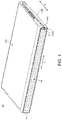
- FIG. 1 is a perspective view illustrating a portable information device according to an embodiment that has been closed into a stacked form.
- FIG. 2 is a schematic plan view of the portable information device illustrated in FIG. 1 that has been opened into a flat form.
- FIG. 3 is a plan view schematically illustrating an internal structure of the portable information device illustrated in FIG. 2 .
- FIG. 4A is a side cross-sectional view schematically illustrating an internal structure of the portable information device in the flat form.
- FIG. 4B is a side cross-sectional view of the portable information device illustrated in FIG. 4A in the stacked form.
- FIG. 5 is a plan view of a spine member.
- FIG. 6 is a schematic side view of the spine member.
- FIG. 7A is an enlarged perspective view schematically illustrating a part of the spine member.
- FIG. 7B is a perspective view illustrating that a cover member is attached to the spine member illustrated in FIG. 7A .
- FIG. 8A is a schematic plan view of the cover member.
- FIG. 8B is a schematic cross-sectional view along a line B-B in FIG. 8A .
- FIG. 1 is a perspective view illustrating a portable information device 10 according to an embodiment that has been closed into a stacked form.
- FIG. 2 is a schematic plan view of the portable information device 10 illustrated in FIG. 1 that has been opened into a flat form.
- FIG. 3 is a plan view schematically illustrating an internal structure of the portable information device 10 illustrated in FIG. 2 .
- the portable information device 10 includes a first chassis 12 A, a second chassis 12 B, a spine member 14 , and a display 16 .
- the portable information device 10 of this embodiment is a tablet PC that is foldable into a double-folded state like a folio.
- the portable information device 10 may alternatively be a mobile phone, a smartphone, an electronic notebook, a portable game machine or the like.
- the chassis 12 A and 12 B are disposed adjacently to each other.
- Each of the chassis 12 A and 12 B is formed of a rectangular plate member having a side wall that is erected from three sides thereof except for a side corresponding to the spine member 14 (adjacent end portions 12 Aa or 12 Ba), for example.
- Each of the chassis 12 A and 12 B is formed of a metal plate of stainless steel, magnesium, aluminum or the like or a fiber-reinforced resin plate containing reinforced fibers such as carbon fibers.
- a direction in which the chassis 12 A and 12 b are arranged side by side, i.e., a transverse direction (width direction) of the spine member 14 is referred to as an X direction
- a direction that is orthogonal to the X direction and extends along the adjacent end portions 12 Aa and 12 Ba, i.e., a longitudinal direction of the spine member 14 is referred to as a Y direction.
- the chassis 12 A and 12 B are coupled to each other by a pair of hinges 17 at the adjacent end portions 12 Aa and 12 Ba.
- the hinges 17 allow the chassis 12 A and 12 B to be relatively rotated between a stacked form illustrated in FIG. 1 and a flat form illustrated in FIG. 2 .
- the hinges 17 are respectively disposed at both ends in the Y direction of the adjacent end portions 12 Aa and 12 Ba of the chassis 12 A and 12 B and are thus located outside the outer peripheral edge portion of the display 16 .
- a rotation center of the chassis 12 A and 12 B defined by the hinges 17 coincides with a front side 16 a of the display 16 .
- the chassis 12 A and 12 B are arranged side by side in the X direction perpendicular to a surface direction thereof and the adjacent end portions 12 Aa and 12 Ba are in contact with each other (see FIGS. 2 and 4A ).
- the chassis 12 A and 12 B are stacked to overlap each other in the surface direction thereof and the adjacent end portions 12 Aa and 12 Ba are separated to form a big gap therebetween (see FIG. 4B ).
- a motherboard 18 , a communication module 19 , a cooling fan 20 , and others are fixed to an inner surface 12 Ab of the first chassis 12 A using a screw or the like.
- An antenna 21 , a battery unit 22 , and others are fixed to an inner surface 12 Bb of the second chassis 12 B using a screw or the like.
- the motherboard 18 is an electronic substrate for controlling the portable information device 10 in general, and unillustrated various electronic components such as a central processing unit (CPU) and a memory are mounted thereon.
- the communication module 19 is a device which processes information transmitted and received by an antenna 21 via various wireless communications such as wireless local area network (WLAN) or wireless wide area network (WWAN).
- the antenna 21 is usually provided in plurality.
- the cooling fan 20 is a device for cooling the CPU and others mounted on the motherboard 18 .
- the battery unit 22 is a power supply for the portable information device 10 and can be charged from an external power source via an unillustrated power cable. Electronic components other than the above may be mounted in the chassis 12 A and 12 B.
- FIG. 4A is a side cross-sectional view schematically illustrating an internal structure of the portable information device 10 in the flat form.
- FIG. 4B is a side cross-sectional view of the portable information device 10 illustrated in FIG. 4A in the stacked form.
- FIGS. 4A and 4B illustrate, in an enlarged manner, the adjacent end portions 12 Aa and 12 Ba of the left and right chassis 12 A and 12 B as well as the periphery thereof.
- the display 16 extends across the chassis 12 A and 12 B.
- the display 16 is a touch panel type liquid crystal display, for example.
- the display 16 is a flexible display such as an organic EL having a paper structure with high flexibility.
- the display 16 is supported by a first plate 24 A and a second plate 24 B and extends across these plates 24 A and 24 B.
- the first plate 24 A is disposed to cover a top opening of the first chassis 12 A.
- the second plate 24 B is disposed to cover a top opening of the second chassis 12 B.
- the plates 24 A and 24 B are arranged adjacent to each other.
- the plates 24 A and 24 B support the display 16 on front sides 24 Ab and 24 Bb thereof.
- a back side 16 b of the display 16 is stuck onto the front sides 24 Ab and 24 Bb of the plates 24 A and 24 B using an adhesive such as a double-sided tape.
- Each of the plates 24 A and 24 B is a thin and hard plate-like member.
- Each of the plates 24 A and 24 B of this embodiment is a fiber-reinforced resin plate produced by impregnating reinforced fibers such as carbon fibers in a matrix resin such as an epoxy resin.
- Each of the plates 24 A and 24 B may be a metal plate of stainless steel or the like.
- Each of the plates 24 A and 24 B is provided with a plurality of attachment pieces 25 that are projected from three outer peripheral end surfaces other than the adjacent end surfaces 24 Aa and 24 Ba (see FIG. 2 ).
- the attachment pieces 25 are respectively screwed to boss portions (not illustrated) erecting from the inner surfaces of the chassis 12 A and 12 B, for example.
- the display 16 is relatively fixed to the chassis 12 A and 12 B via the plates 24 A and 24 B. This causes the plates 24 A and 24 B to be rotated integrally with the chassis 12 A and 12 B, which results in bending the display 16 .
- the plates 24 A and 24 B may be fixed to the chassis by screwing back sides thereof directly to the boss portion or the like instead of screwing a part or all of the attachment pieces 25 .
- the plates 24 A and 24 B are arranged adjacent to each other in a direction perpendicular to the surface direction thereof so that the adjacent end surfaces 24 Aa and 24 Ba are in contact with each other.
- the display 16 serves as a large screen opened into a flat shape.
- the adjacent end surfaces 24 Aa and 24 Ba of the plates 24 A and 24 B are separated from each other.
- the display 16 is folded into a substantial U-shape.
- the display 16 includes a bending region R in an area across the adjacent end surfaces 24 Aa and 24 Ba of the plates 24 A and 24 B.
- the bending region R which is a belt-like region that is shorter in the X direction and longer in the Y direction, is provided to bridge the adjacent end portions 12 Aa and 12 Ba of the chassis 12 A and 12 B. It is the bending region R that is bent when the chassis 12 A and 12 B change from the flat form into the stacked form.
- the display 16 may be flexible only in the bending region R.
- An area of the back side 16 b of the display 16 other than the bending region R is fixed to the front side 24 Ab of the first plate 24 A.
- An area of the back side 16 b of the display 16 other than the bending region R is fixed to the front side 24 Bb of the second plate 24 B.
- an adhesive such as a double-sided tape is used, for example.
- the bending region R which is not fixed to the plates 24 A and 24 B, is movable relative to the front sides 24 Ab and 24 Bb.
- Each of the plates 24 A and 24 B is provided with a locking claw 26 A and 26 B on the back sides thereof.
- the locking claw 26 A provided on the back side of the first plate 24 A protrudes beyond the adjacent end surfaces 24 Aa and 24 Ba to contact the back side of the second plate 24 B.
- the locking claw 26 B provided on the back side of the second plate 24 B protrudes beyond the adjacent end surfaces 24 Ba and 24 Aa to contact the back side of the first plate 24 A.
- the locking claws 26 A and 26 B are provided in plurality (three) each and arranged in parallel (see FIG. 2 ). For example, the three locking claws 26 A and 26 B each are aligned along a side of a plate.
- upper surfaces of tips of locking claws 26 A and 26 B are respectively in contact with the back sides of the plates 24 B and 24 A to suppress a level difference between the plates 24 A and 24 B. This allows an extremely flat plane to be formed and maintained by the front sides 24 Ab and 24 Bb of the plates 24 A and 24 B.
- the locking claws 26 A and 26 B may be omitted.
- FIG. 5 is a plan view of a spine member 14 .
- FIG. 6 is a schematic side view of the spine member 14 .
- FIG. 6 some of a plurality of cover members 52 described below are illustrated as attached and some as exploded.
- FIG. 7A is an enlarged perspective view schematically illustrating a part of the spine member 14 .
- the spine member 14 covers a gap between the adjacent end portions 12 Aa and 12 Ba that is generated when the chassis 12 A and 12 B change from the flat form into the stacked form.
- the spine member 14 thus prevents components such as the display 16 , the plates 24 A and 24 B, the motherboard 18 , and the battery unit 22 housed in the chassis 12 A and 12 B from being exposed to an outside in the stacked form.
- the spine member 14 is a thin plate member that is flexible in the X direction.
- the spine member 14 is provided across the inner surfaces 12 Ab and 12 Bb of the chassis 12 A and 12 B to bridge and cover the adjacent end portions 12 Aa and 12 Ba from an inside.
- the spine member 14 includes a sheet member 32 , a distal post member 34 , a proximal post member 35 , and a plurality of post members 36 a , 36 b , 36 c , and 36 d.
- the sheet member 32 is a flexible, high-strength sheet and has such a width dimension in the X direction that, in the stacked form, it can cover the gap between the adjacent end portions 12 Aa and 12 Ba of the chassis 12 A and 12 B (see FIG. 4B ).
- the sheet member 32 is a triaxial woven fabric made of carbon fibers, glass fibers, polyethylene terephthalate (PET) fibers or the like that have been triaxially woven together, for example. In particular, such a triaxial woven fabric is impregnated in a matrix resin to produce a triaxial woven prepreg.
- the sheet member 32 may alternatively be another fabric such as a biaxial fabric, a resin sheet, a metal sheet, or the like.
- Each of the post members 34 , 35 , and 36 a to 36 d is a thin and narrow strip-like plate formed of a resin, metal, or the like.
- the distal post member 34 and the proximal post member 35 are wider in the X direction than the post members 36 a to 36 d therebetween.
- the post members 34 , 35 , and 36 a to 36 d may all have same or different width dimensions in the X direction as appropriate.
- the distal post member 34 , the post members 36 a to 36 d , and the proximal post member 35 are arranged side by side in this order from the first chassis 12 A toward the second chassis 12 B.
- the post members 34 , 35 , and 36 a to 36 d are adhered to be fixed to a front side of the sheet member 32 using a gluing agent or an adhesive such as a double-sided tape.
- the spine member 14 is bent from a flat shape to a substantial U-shape.
- the post members 34 , 35 , and 36 a to 36 d and the sheet member 32 may be integrally molded by a resin.
- Thin plate portions 38 are provided at longitudinal end portions of the post members 34 , 35 , and 36 a to 36 d .
- the thin plate portions 38 are slidably held on a bottom surface side of the hinges 17 (see FIG. 3 ).
- the distal post member 34 has a trapezoidal cross section, and a leg thereof on the first chassis 12 A side is orthogonal to upper and lower bases thereof.
- the distal post member 34 is placed on the inner surface 12 Ab of the first chassis 12 A and is slidable in the X direction relative to the inner surface 12 Ab.
- a side surface 34 a of the distal post member 34 on the second chassis 12 B side faces a side surface 40 a of the adjacent post member 36 a .
- the side surface 34 a is an inclined surface inclined in a direction from the second chassis 12 B toward the first chassis 12 A as it goes from a back side (a surface on the sheet member 32 side) toward a front side (a surface on the first plate 24 A side) of the spine member 14 (see FIG. 4A ). In other words, the side surface 34 a is inclined in a direction away from the post member 36 a as it goes upward.
- the distal post member 34 is biased by a spring 42 in the X direction (see FIG. 3 ).
- the spring 42 continuously biases the spine member 14 in the X direction toward the first chassis 12 A side via the distal post member 34 .
- the proximal post member 35 has a trapezoidal cross section, and a leg thereof on the second chassis 12 B side is orthogonal to upper and lower bases thereof.
- the proximal post member 35 is placed on the inner surface 12 Bb of the second chassis 12 B and is fixed to be immovable relative to the inner surface 12 Bb.
- the proximal post member 35 is provided with an attachment hole 43 penetrating in a thickness direction at an appropriate longitudinal location (see FIG. 5 ).
- a screw 44 is inserted through the attachment hole 43 .
- the screw 44 is screwed through the attachment hole 43 into an unillustrated female threaded portion provided on the inner surface 12 Bb of the second chassis 12 B.
- the proximal post member 35 i.e., the spine member 14 is thus fixed to the second chassis 12 B.
- a side surface 35 a of the proximal post member 35 on the first chassis 12 A side faces a side surface 40 b of the adjacent post member 36 d .
- the side surface 35 a is an inclined surface inclined in a direction from the first chassis 12 A toward the second chassis 12 B as it goes from the back side toward the front side of the spine member 14 (see FIG. 4A ). In other words, the side surface 35 a is inclined in a direction away from the post member 36 d as it goes upward.
- Each of the post members 36 a to 36 d has a trapezoidal cross section.
- the post members 36 a to 36 d are placed on the inner surface 12 Ab of the first chassis 12 A and are slidable in the X direction relative to the inner surface 12 Ab.
- Each of the post members 36 a to 36 d has a side surface 40 a on the first chassis 12 A side and a side surface 40 b on the second chassis 12 B side.
- the side surface 40 a is an inclined surface inclined in a direction from the first chassis 12 A toward the second chassis 12 B as it goes from the back side toward the front side of the spine member 14 .
- the side surface 40 b is an inclined surface inclined in a direction from the second chassis 12 B toward the first chassis 12 A as it goes from the back side toward the front side of the spine member 14 .
- the outermost post members 36 a and 36 d are shaped symmetrically to each other and the intermediate post members 36 b and 36 c are shaped symmetrically to each other.
- the number of the post members 36 a to 36 d to be provided can be changed as appropriate.
- the proximal post member 35 is fixed to the second chassis 12 B, and the distal post member 34 and the post members 36 a to 36 d are supported to be movable in the X direction relative to the first chassis 12 A.
- the proximal post member 35 may be fixed to the first chassis 12 A and the distal post member 34 may be arranged on the second chassis 12 B side.
- a plurality of grooves 46 and a plurality of relief grooves 48 are provided on the front side 14 a of the spine member 14 .
- Each groove 46 is formed by partially recessing the front side 14 a of the spine member 14 and extends along the X direction like a canal. In other words, each groove 46 is formed by recessing a part of each post member 34 , 35 , and 36 a to 36 d at same locations in the Y direction on the front side 14 a so that the grooves together form a continuous groove shape in the X direction.
- Each groove 46 serves as a passage for a cable 50 extending across the left and right chassis 12 A and 12 B (see FIGS. 3, 6, and 7A ). Passing through the groove 46 prevents the cable 50 from being displaced or lifted on the front side 14 a during the rotation of the chassis 12 A and 12 B. Accordingly, the cable 50 will not be caught between other components or subjected to such an excessive force that causes a connection terminal thereof to come off during the rotation of the chassis 12 A and 12 B.
- Each relief groove 48 is provided in a longitudinal direction of the spine member 14 , for example.
- Each relief groove 48 is formed in the same manner as the groove 46 but has a smaller width dimension in the Y direction than that of the groove 46 .
- the relief grooves 48 serve as escape spaces so that the locking claws 26 A and 26 B protruding beyond the adjacent end surfaces 24 Aa and 24 Ba of the plates 24 A and 24 B do not interfere with the front side 14 a during the rotation of the chassis 12 A and 12 B.
- cover members 52 that cover the grooves 46 are attached to the front side 14 a of the spine member 14 . Note that the cover members 52 are detached in FIGS. 3, 5, and 7A .
- FIG. 7B is a perspective view illustrating that the cover member 52 is attached to the spine member 14 illustrated in FIG. 7A .
- FIG. 8A is a schematic plan view of the cover member 52 .
- FIG. 8B is a schematic cross-sectional view along a line B-B in FIG. 8A .
- the cover member 52 serves as a cap that covers the groove 46 to prevent the cable 50 from lifting and coming off.
- the cover member 52 also serves as a protection member that protects components (in this embodiment, the plates 24 A and 24 B) in the chassis 12 A and 12 B from contact with the spine member 14 .
- the cover member 52 extends over the entire X-direction length of the groove 46 and thus covers the groove 46 .
- the cover member 52 may extend over the entire Y-direction length of the spine member 14 .
- the cover member 52 includes a distal sheet portion 52 a , a cushion portion 52 b , an attachment portion 52 c and an auxiliary cover portion 52 d.
- the distal sheet portion 52 a is a laminated sheet thinner than the cushion portion 52 b .
- the distal sheet portion 52 a occupies a predetermined area of the cover member on the first chassis 12 A side including a first end portion.
- the distal sheet portion 52 a is a three-layer structure formed by laminating a front side sheet 54 , a base sheet 55 , and a back side sheet 56 in this order from a front side (the plates 24 A and 24 B side) to a back side (the spine member 14 side) of the cover member 52 (see FIG. 8B ).
- the front side sheet 54 extends across the entire X-direction length of the cover member 52 and forms a front side thereof.
- the front side sheet 54 is adhered to be fixed to a front side of the base sheet 55 using a gluing agent or an adhesive.
- the front side sheet 54 is a flexible thin sheet formed of polytetrafluoroethylene (PTFE), for example.
- a thickness of the front side sheet 54 is about 0.08 mm, for example.
- the front side sheet 54 is preferably formed of a resin with self-lubricity such as PTFE so that friction and wear can be reduced when the distal sheet portion is slid into an opening 60 a as will be described later.
- the front side sheet 54 may be formed of a resin other than PTFE such as a nylon-based resin or the like.
- the front side sheet 54 is preferably transparent or translucent.
- the base sheet 55 extends over the entire X-direction length of the cover member 52 and serves as a base thereof.
- the base sheet 55 is laminated between the front side sheet 54 and the back side sheet 56 and is adhered to be fixed to the sheets 54 and 56 using a gluing agent or an adhesive.
- the base sheet 55 is a flexible thin sheet formed of PET, for example.
- a thickness of the base sheet 55 is about 0.2 mm, for example, which is greater than that of the front side sheet 54 .
- the base sheet 55 may be formed of a nylon-based resin or the like or a thin metal film such as stainless steel.
- the base sheet 55 is preferably transparent or translucent.
- the back side sheet 56 extends over the entire X-direction length of the cover member 52 and forms a back side thereof.
- the back side sheet 56 is laminated on a back side of the base sheet 55 and is adhered to be fixed to the base sheet 55 using a gluing agent or an adhesive.
- the back side sheet 56 may be formed of the same material as the front side sheet 54 (PTFE, for example) and may have the same thickness (0.08 mm, for example).
- the back side sheet 56 may be formed of a different material and may have a different thickness from the front side sheet 54 .
- the back side sheet 56 is preferably transparent or translucent.
- the cushion portion 52 b is a laminated sheet thicker than the distal sheet portion 52 a and the auxiliary cover portion 52 d .
- the cushion portion 52 b is provided between the distal sheet portion 52 a and the attachment portion 52 c in the X direction and overlaps at least partially with the front side 14 a of the post members 36 b to 36 d .
- the cushion portion 52 b faces an internal space between the chassis 12 A and 12 B, i.e., the bending region R of the display 16 and the plates 24 A and 24 B (see FIG. 4B ).
- the cushion portion 52 b is of a five-layer structure formed by laminating the front side sheet 54 , a protection sheet 57 , a cushion material 58 , the base sheet 55 and the back side sheet 56 in this order from the front side to the back side of the cover member 52 .
- the front side sheet 54 , the base sheet 55 and the back side sheet 56 of the cushion portion 52 b are common with those of the distal sheet portion 52 a.
- the protection sheet 57 extends over the entire X-direction length of the cushion portion 52 b . More specifically, the protection sheet 57 is provided to cover only a front side of the cushion material 58 .
- the protection sheet 57 is laminated between the front side sheet 54 and the cushion material 58 and is adhered to be fixed to a back side of the front side sheet 54 and a front side of the cushion material 58 using a gluing agent or an adhesive.
- the protection sheet 57 is a flexible thin sheet formed of PET, for example.
- a thickness of the protection sheet 57 is smaller than that of the front side sheet 54 or the base sheet 55 and is about 0.05 mm, for example.
- the protection sheet 57 can protect the front side of the cushion material 58 , it may be formed of a resin other than PET, a metal foil, or others.
- the cushion material 58 is laminated between the protection sheet 57 and the base sheet 55 and is adhered to be fixed to a back side of the protection sheet 57 and a front side of the base sheet 55 using a gluing agent or an adhesive.
- the cushion material 58 is a flexible spongy sheet formed of a polyurethane resin, for example. Among the five layers of the cushion portion 52 b , a thickness of the cushion material 58 is the greatest and is 0.25 mm, for example. This allows the cushion material 58 to exhibit high shock absorbing performance.
- the cushion material 58 on the front side of which the protection sheet 57 has been stuck in advance, is disposed between the base sheet 55 and the front side sheet 54 .
- the cushion material 58 may be of a material and/or structure having certain cushioning property. For example, it may be formed of a spongy resin material other than polyurethane or flexible rubber.
- the attachment portion 52 c attaches the cover member 52 to the spine member 14 .
- the attachment portion 52 c is formed of a hard resin and has a rectangular sectional shape.
- the attachment portion 52 c extends over the entire Y-direction width of the cover member 52 , and an X-direction length dimension of the attachment portion is somewhat smaller than or equal to the width dimension of the proximal post member 35 .
- the attachment portion 52 c is disposed next to the cushion portion 52 b and is fixed to a front side of the front side sheet 54 using a double-sided tape or a gluing agent.
- the attachment portion 52 c is provided with attachment holes 59 formed through respective longitudinal (Y-direction) end portions thereof. A screw 44 is inserted into each attachment hole 59 to fix the spine member 14 to the second chassis 12 B. The cover member 52 is then co-fastened to the second chassis 12 B together with the spine member 14 .
- the cover member 52 may alternatively be fixed only to the spine member 14 using a screw, a gluing agent, or others.
- the attachment portion 52 c may be omitted. In that case, a part of the cushion portion 52 b or the auxiliary cover portion 52 d may be adhered to be fixed to the front side 14 a of the spine member 14 using a gluing agent, a double-sided tape or the like.
- the attachment portion 52 c may also be provided with the front side sheet 54 .
- the attachment portion 52 c may not be provided with the base sheet 55 and the back side sheet 56 .
- the auxiliary cover portion 52 d is arranged at a location off the groove 46 when seen in plan view.
- the auxiliary cover portion 52 d prevents the cable 50 drawn out of the groove 46 (to the second chassis 12 B side) from lifting.
- the auxiliary cover portion 52 d is a piece of thin sheet extending farther to the second chassis 12 B side than the attachment portion 52 c.
- the auxiliary cover portion 52 d is of a three-layer structure formed by laminating the front side sheet 54 , the base sheet 55 and the back side sheet 56 .
- the auxiliary cover portion 52 d is of the same structure and thickness as the distal sheet portion 52 a .
- the auxiliary cover portion 52 d may omit the front side sheet 54 , for example.
- the auxiliary cover portion 52 d protrudes from an X-direction end side of the attachment portion 52 c to the second chassis 12 B side and has a substantially trapezoidal shape in plan view.
- the auxiliary cover portion 52 d may have a rectangular shape in plan view or may protrude from an entire Y-direction length of the attachment portion 52 c to the second chassis 12 B side.
- the auxiliary cover portion 52 d may be omitted.
- the cover member 52 is disposed to cover the groove 46 as a whole, and the attachment portion 52 c is arranged on the front side 14 a of the proximal post member 35 .
- the cover member 52 is fixed to the second chassis 12 B together with the spine member 14 by tightening the screws 44 through the attachment holes 59 and 43 .
- the distal sheet portion 52 a is placed on a bottom surface of a step 60 a which is lower than the front side 14 a of the walls on both sides in the Y direction of the groove 46 in the distal post member 34 (see FIG. 6 ).
- a retaining member 60 spanning above the distal sheet portion 52 a is disposed on the front side 14 a of the distal post member 34 .
- the retaining member 60 is fixed by inserting a screw 62 (see FIG. 7B ) into a screw hole 34 c provided on the front side 14 a of the distal post member 34 (see FIG. 5 ).
- a gap for a height of the step 60 a is generated between the retaining member 60 and the bottom surface of the step 60 a (note that this gap is denoted with the same symbol as the step 60 a and is called an “opening 60 a ”).
- the distal sheet portion 52 a is inserted in a slidable manner in the X direction. It is thus preferable that the distal sheet portion 52 a is as thin as possible.
- the distal sheet portion 52 a of the cover member 52 of this embodiment is not provided with the cushion material 58 and the protection sheet 57 .
- the distal sheet portion 52 a may be of the same structure as the cushion portion 52 b .
- An external surface of the distal sheet portion 52 a is constituted by the front side sheet 54 and the back side sheet 56 formed of PTFE, which allows a smooth sliding of the distal sheet portion 52 a into the opening 60 a.
- the attachment portion 52 c (and the auxiliary cover portion 52 d ) of the cover member 52 on the second chassis 12 B side is fixed to be immovable relative to the spine member 14 , while the distal sheet portion 52 a and the cushion portion 52 b on the first chassis 12 A side are supported to be movable relative to the spine member 14 . It is alternatively possible to arrange the attachment portion 52 c of the cover member 52 on the first chassis 12 A side and the distal sheet portion 52 a on the second chassis 12 B side, of course.
- the cover member 52 of this embodiment is provided with positioning holes 52 e to prevent the cover member from being attached to the spine member 14 upside down or at a wrong position.
- the positioning holes 52 e are respectively provided in Y-direction end portions of the attachment portion 52 c and are respectively spaced apart from the attachment holes 59 by different distances.
- On the front side 14 a of the proximal post member 35 positioning pins 35 b are projected at positions corresponding to the positioning holes 52 e (see FIG. 5 ). Inserting the positioning pins 35 b into the positioning holes 52 e of the attachment portion 52 c prevents the cover member 52 from being attached upside down or at a wrong position.
- the positioning holes 52 e and the positioning pins 35 b are particularly important for the cushion portion 52 b to be placed at a right position so that the front side of the cushion material 58 is protected by the protection sheet 57 as described later.
- a pair of positioning holes 60 b is provided in the retaining member 60
- a pair of positioning pins 34 b to be inserted into the positioning holes 60 b is provided on the front side 14 a of the distal post member 34 .
- the distal post member 34 , the post members 36 a to 36 d , and the proximal post member 35 of the spine member 14 are arranged planarly along the X direction across the adjacent end portions 12 Aa and 12 Ba of the chassis 12 A and 12 B that are in contact with each other.
- the distal post member 34 of the spine member 14 has been slid to a position farthest to the first chassis 12 A side.
- Substantially V-shaped gaps have been respectively formed between the opposing side surfaces 34 a and 40 a , 40 b and 40 a , and 40 b and 35 a.
- the attachment portion 52 c of the cover member 52 is fixed to the proximal post member 35 and extends in the X direction on the front side 14 a of the spine member 14 to the first chassis 12 A side.
- a distal tip of the distal sheet portion 52 a of the cover member 52 is inserted into the opening 60 a provided at the distal post member 34 .
- the spine member 14 As the spine member 14 is located on the outer side than the rotation center, it receives a tensile force in the X direction during the rotation.
- the proximal post member 35 which is fixed to the second chassis 12 B, then pulls the distal post member 34 toward the second chassis 12 B side, so that the spine member 14 is slid over the inner surface 12 Ab of the first chassis 12 A.
- the cover member 52 also receives a tensile force in the X direction during the rotation because it is located on the outer side than the rotation center.
- the attachment portion 52 c which is fixed to the second chassis 12 B, then pulls the distal sheet portion 52 a toward the second chassis 12 B side, so that the cover member 52 is slid over the front side 14 a of the spine member 14 .
- the now curved spine member 14 cover and hide the big gap generated between the adjacent end portions 12 Aa and 12 Ba of the chassis 12 A and 12 B from an inside.
- the opposing side surfaces 34 a and 40 a , 40 b and 40 a , 40 b and 35 a of the spine member 14 are then in contact with each other to serve together as a highly-rigid post in which the distal post member 34 , the post members 36 a to 36 d , and the proximal post member 35 are continued to form a curve like a backbone.
- the spine member 14 then functions as a post that reinforces the gap between the separated chassis 12 A and 12 B.
- the adjacent end surfaces 24 Aa and 24 Ba must be in contact with each other without any gap so that the plates 24 A and 24 B form a stepless flat surface to support the display 16 .
- the adjacent end surfaces 24 Aa and 24 Ba are therefore formed as sharp edges and, in the stacked form, protrude toward the front side 14 a of the spine member 14 (see FIG. 4B ). If the portable information device 10 is subjected to a shock such as dropping in the stacked form, these adjacent end surfaces 24 Aa and 24 Ba may violently contact the hard front side 14 a of the spine member 14 and be chipped, cracked or damaged in other ways.
- the edges are particularly easily chipped by impact because the plates 24 A and 24 B are formed of a fiber-reinforced resin plate.
- the cover member 52 of this embodiment curves along the front side 14 a of the spine member 14 in the stacked form so that the cushion portion 52 b (cushion material 58 ) faces the adjacent end surfaces 24 Aa and 24 Ba of the plates 24 A and 24 B (see FIG. 4B ).
- the cushion 52 b then absorb the shock, which prevents the edges of the adjacent end surfaces 24 Aa and 24 Ba from being damaged despite the interference between the adjacent end surfaces 24 Aa and 24 Ba and the cover member 52 .
- the cover member 52 is disposed to overlap only the groove 46 .
- the cover member 52 is positioned closer to the adjacent end surfaces 24 A and 24 Ba than the front side 14 a of the spine member 14 by a thickness of the cushion portion 52 b , when the portable information device 10 is subjected to a shock in the stacked form, the adjacent end surfaces 24 Aa and 24 Ba come in touch with the cushion portion 52 b first and are thus prevented from interfering with the hard front side 14 a .
- the front side of the cushion material 58 is provided with the protection sheet 57 that is formed of PET, for example, and is more resistant to scratch or curling up than the front side sheet 54 .
- the cushion portion 52 b of this embodiment includes the protection sheet 57 to provide a hard front side. This prevents the front side sheet 54 and the cushion material 58 from being caught by the edges of the plates 24 A and 24 B when they slide on the front side and thus from damaging one another.
- the relief groove 48 provided on the front side 14 a of the spine member 14 allows the interference between the locking claws 26 A and 26 B and the front side 14 a to be avoided.
- the cover member 52 is provided because it plays an important role to prevent the lifting of the cable 50 passing through the spine member 14 in the X direction.
- the cushion portion 52 b may be provided elsewhere than on the cover member 52 . That is, the cushion portion 52 b may be directly stuck onto the front side 14 a of the spine member 14 , for example. The cushion portion 52 b would then still prevent the cushion material 58 from being damaged as long as the protection sheet 57 is provided on the front side of the cushion material 58 .
- the cover member 52 may be provided not to restrain the cable 50 but only to dispose the cushion portion 52 b thereon. Providing the cover member 52 makes it easy to dispose the cushion portion 52 b . As the cover member 52 is slid in accordance with the movement of the spine member 14 , the cushion portion 52 b can smoothly follow the movement of the spine member 14 .
- the cover member 52 of this embodiment is partially provided with the cushion portion 52 b including the cushion material 58 formed of polyurethane or the like which is opaque and makes the cable 50 therebehind invisible.
- the three sheets 54 to 56 laminated to form the distal sheet portion 52 a are all transparent or translucent.
- the cable 50 behind the distal sheet portion 52 a can therefore be easily viewed therethrough, which contributes to prevention of an erroneous assembly in manufacturing, for example.
- the cushion material 58 may also be transparent or translucent.
- the attachment portion 52 c may be omitted to allow the cable 50 behind the entire cover member 52 to be viewed.
- the display 16 has been exemplarily shown as a flexible display having the bending region R.
- the top surfaces of the chassis 12 A and 12 B are respectively provided with displays (dual displays).
- the plates 24 A and 24 B are no longer necessary.
- Providing the cushion portion 52 b at a position facing the end surface of each display in the stacked form prevents the end surface of each display from being damaged.
- the plates 24 A and 24 B may not always be necessary depending on specification of the portable information device 10 . Providing the cushion portion 52 b in such a portable information device 10 would prevent the motherboard 18 from being damaged due to an interference between an end surface of the motherboard 18 and the spine member 14 .
- the portable information device 10 may be configured not only with two chassis of the same shape connected to each other in a foldable manner, but also with: a larger chassis and two smaller chassis foldably coupled to the left and right edge portions of the larger chassis like double doors; one chassis to each of left and right sides thereof a chassis is coupled, wherein the left and right chassis have different folding directions so that the three chassis form an S-shape; a larger chassis and a smaller chassis foldably connected to either one of left and right edge portions of the larger chassis to form a J-shape, for example.
- Four or more chassis may be coupled to each other.
Landscapes
- Engineering & Computer Science (AREA)
- Computer Hardware Design (AREA)
- Theoretical Computer Science (AREA)
- Physics & Mathematics (AREA)
- Human Computer Interaction (AREA)
- General Engineering & Computer Science (AREA)
- General Physics & Mathematics (AREA)
- Mathematical Physics (AREA)
- Casings For Electric Apparatus (AREA)
- Telephone Set Structure (AREA)
Abstract
Description
Claims (9)
Applications Claiming Priority (3)
| Application Number | Priority Date | Filing Date | Title |
|---|---|---|---|
| JP2020090148 | 2020-05-23 | ||
| JP2020090148A JP2021185444A (en) | 2020-05-23 | 2020-05-23 | Portable information device |
| JPJP2020090148 | 2020-05-23 |
Publications (2)
| Publication Number | Publication Date |
|---|---|
| US20210365072A1 US20210365072A1 (en) | 2021-11-25 |
| US11301007B2 true US11301007B2 (en) | 2022-04-12 |
Family
ID=78608985
Family Applications (1)
| Application Number | Title | Priority Date | Filing Date |
|---|---|---|---|
| US16/930,491 Active 2040-08-19 US11301007B2 (en) | 2020-05-23 | 2020-07-16 | Portable information device |
Country Status (2)
| Country | Link |
|---|---|
| US (1) | US11301007B2 (en) |
| JP (1) | JP2021185444A (en) |
Cited By (3)
| Publication number | Priority date | Publication date | Assignee | Title |
|---|---|---|---|---|
| US20220397936A1 (en) * | 2021-06-11 | 2022-12-15 | Samsung Electronics Co., Ltd. | Hinge apparatus and electronic device including the same |
| US20230088731A1 (en) * | 2021-09-21 | 2023-03-23 | Microsoft Technology Licensing, Llc | Fabric Hinged Device |
| US20250190022A1 (en) * | 2022-03-30 | 2025-06-12 | Microsoft Technology Licensing, Llc | Computing device slider plate |
Families Citing this family (9)
| Publication number | Priority date | Publication date | Assignee | Title |
|---|---|---|---|---|
| JP2022047813A (en) * | 2020-09-14 | 2022-03-25 | レノボ・シンガポール・プライベート・リミテッド | Portable information device and cover device |
| JP2022067198A (en) * | 2020-10-20 | 2022-05-06 | レノボ・シンガポール・プライベート・リミテッド | Portable information device and display assembly |
| KR102829215B1 (en) * | 2020-12-14 | 2025-07-02 | 엘지디스플레이 주식회사 | Foldable display device |
| JP2022112403A (en) * | 2021-01-21 | 2022-08-02 | 株式会社Joled | Display device |
| KR20220106258A (en) * | 2021-01-21 | 2022-07-29 | 삼성디스플레이 주식회사 | Electronic device |
| JP7170086B2 (en) * | 2021-04-22 | 2022-11-11 | レノボ・シンガポール・プライベート・リミテッド | Electronics |
| KR102933928B1 (en) * | 2022-02-09 | 2026-03-04 | 삼성디스플레이 주식회사 | Display device |
| US12061499B2 (en) | 2022-03-28 | 2024-08-13 | Microsoft Technology Licensing, Llc | Computing device hinge with sliding cover |
| US12194852B2 (en) * | 2022-04-28 | 2025-01-14 | Panasonic Automotive Systems Co., Ltd. | Display device and input device |
Citations (4)
| Publication number | Priority date | Publication date | Assignee | Title |
|---|---|---|---|---|
| US9506279B2 (en) * | 2013-11-13 | 2016-11-29 | Nokia Technologies Oy | Apparatus and method of providing an apparatus comprising a bendable portion |
| US20170300089A1 (en) * | 2016-04-19 | 2017-10-19 | Dell Products L.P. | Information Handling System Low Profile Housing and Hinge Assembly |
| JP2018112834A (en) | 2017-01-10 | 2018-07-19 | レノボ・シンガポール・プライベート・リミテッド | Portable information equipment |
| US10558242B2 (en) * | 2017-12-27 | 2020-02-11 | Lg Display Co., Ltd. | Foldable display device |
-
2020
- 2020-05-23 JP JP2020090148A patent/JP2021185444A/en active Pending
- 2020-07-16 US US16/930,491 patent/US11301007B2/en active Active
Patent Citations (5)
| Publication number | Priority date | Publication date | Assignee | Title |
|---|---|---|---|---|
| US9506279B2 (en) * | 2013-11-13 | 2016-11-29 | Nokia Technologies Oy | Apparatus and method of providing an apparatus comprising a bendable portion |
| US20170300089A1 (en) * | 2016-04-19 | 2017-10-19 | Dell Products L.P. | Information Handling System Low Profile Housing and Hinge Assembly |
| JP2018112834A (en) | 2017-01-10 | 2018-07-19 | レノボ・シンガポール・プライベート・リミテッド | Portable information equipment |
| US10082827B2 (en) * | 2017-01-10 | 2018-09-25 | Lenovo (Singapore) Pte. Ltd. | Portable information device |
| US10558242B2 (en) * | 2017-12-27 | 2020-02-11 | Lg Display Co., Ltd. | Foldable display device |
Cited By (5)
| Publication number | Priority date | Publication date | Assignee | Title |
|---|---|---|---|---|
| US20220397936A1 (en) * | 2021-06-11 | 2022-12-15 | Samsung Electronics Co., Ltd. | Hinge apparatus and electronic device including the same |
| US12277004B2 (en) * | 2021-06-11 | 2025-04-15 | Samsung Electronics Co., Ltd. | Hinge apparatus and electronic device including the same |
| US20230088731A1 (en) * | 2021-09-21 | 2023-03-23 | Microsoft Technology Licensing, Llc | Fabric Hinged Device |
| US12079045B2 (en) * | 2021-09-21 | 2024-09-03 | Microsoft Technology Licensing, Llc | Fabric hinged device |
| US20250190022A1 (en) * | 2022-03-30 | 2025-06-12 | Microsoft Technology Licensing, Llc | Computing device slider plate |
Also Published As
| Publication number | Publication date |
|---|---|
| JP2021185444A (en) | 2021-12-09 |
| US20210365072A1 (en) | 2021-11-25 |
Similar Documents
| Publication | Publication Date | Title |
|---|---|---|
| US11301007B2 (en) | Portable information device | |
| US10386886B2 (en) | Portable information device | |
| US10185355B2 (en) | Portable information device | |
| US11096294B2 (en) | Portable information device and display assembly | |
| US10481634B2 (en) | Portable information device | |
| US11455004B2 (en) | Portable information device | |
| US10416710B2 (en) | Portable information device | |
| US10863635B2 (en) | Portable information device | |
| JP6535353B2 (en) | Portable information equipment | |
| CN116469308A (en) | Foldable electronic device including display protective structure | |
| US11287854B2 (en) | Portable information apparatus | |
| US8416561B2 (en) | Battery-mounting structure | |
| US8373979B2 (en) | Electronic apparatus | |
| US20220137669A1 (en) | Portable information device and double-sided adhesive tape | |
| JP6491770B2 (en) | Portable information equipment | |
| JP6636125B1 (en) | Portable information equipment | |
| JP6686115B1 (en) | Portable information equipment | |
| US11409331B2 (en) | Portable information device and cover device | |
| JP6532972B2 (en) | Portable information equipment | |
| US20070023733A1 (en) | Electronic apparatus | |
| JP6421263B2 (en) | Portable information equipment | |
| JP6928153B2 (en) | Portable information equipment | |
| US20250231595A1 (en) | Display assembly and electronic apparatus | |
| KR20240085936A (en) | The cellphone case that have a radiant heat function |
Legal Events
| Date | Code | Title | Description |
|---|---|---|---|
| AS | Assignment |
Owner name: LENOVO (SINGAPORE) PTE. LTD., SINGAPORE Free format text: ASSIGNMENT OF ASSIGNORS INTEREST;ASSIGNORS:KINOSHITA, HIROAKI;USHIODA, TATSUYA;YAMAUCHI, TAKEHITO;AND OTHERS;REEL/FRAME:053225/0480 Effective date: 20200715 |
|
| FEPP | Fee payment procedure |
Free format text: ENTITY STATUS SET TO UNDISCOUNTED (ORIGINAL EVENT CODE: BIG.); ENTITY STATUS OF PATENT OWNER: LARGE ENTITY |
|
| STPP | Information on status: patent application and granting procedure in general |
Free format text: NON FINAL ACTION MAILED |
|
| STPP | Information on status: patent application and granting procedure in general |
Free format text: RESPONSE TO NON-FINAL OFFICE ACTION ENTERED AND FORWARDED TO EXAMINER |
|
| STPP | Information on status: patent application and granting procedure in general |
Free format text: PUBLICATIONS -- ISSUE FEE PAYMENT RECEIVED |
|
| STPP | Information on status: patent application and granting procedure in general |
Free format text: PUBLICATIONS -- ISSUE FEE PAYMENT VERIFIED |
|
| STCF | Information on status: patent grant |
Free format text: PATENTED CASE |
|
| AS | Assignment |
Owner name: LENOVO SWITZERLAND INTERNATIONAL GMBH, SWITZERLAND Free format text: ASSIGNMENT OF ASSIGNORS INTEREST;ASSIGNOR:LENOVO PC INTERNATIONAL LIMITED;REEL/FRAME:070269/0092 Effective date: 20241231 |
|
| MAFP | Maintenance fee payment |
Free format text: PAYMENT OF MAINTENANCE FEE, 4TH YEAR, LARGE ENTITY (ORIGINAL EVENT CODE: M1551); ENTITY STATUS OF PATENT OWNER: LARGE ENTITY Year of fee payment: 4 |