CROSS-REFERENCE TO RELATED APPLICATIONS
Not Applicable
STATEMENT REGARDING FEDERALLY SPONSORED RESEARCH OR DEVELOPMENT
Not Applicable
THE NAMES OF THE PARTIES TO A JOINT RESEARCH AGREEMENT
Not Applicable
INCORPORATION-BY-REFERENCE OF MATERIAL SUBMITTED ON A COMPACT DISC OR AS A TEXT FILE VIA THE OFFICE ELECTRONIC FILING SYSTEM
Not Applicable
STATEMENT REGARDING PRIOR DISCLOSURES BY THE INVENTOR OR JOINT INVENTOR
Not Applicable
BACKGROUND OF THE INVENTION
(1) Field of the Invention
The disclosure relates to hot object protective covering and more particularly pertains to a new hot object protective covering for an iron to prevent injuries from burns caused by a base of heated iron.
(2) Description of Related Art Including Information Disclosed Under 37 CFR 1.97 and 1.98
The prior art relates to hot object protective coverings used to prevent accidental burns.
BRIEF SUMMARY OF THE INVENTION
An embodiment of the disclosure meets the needs presented above by generally comprising a panel that has a top side, a bottom side and a perimeter edge. The top side has a size and shape of a base of an iron. The panel comprises a flexible and heat resistant material. A securing member is configured to releasably secure the panel to the base of the iron.
There has thus been outlined, rather broadly, the more important features of the disclosure in order that the detailed description thereof that follows may be better understood, and in order that the present contribution to the art may be better appreciated. There are additional features of the disclosure that will be described hereinafter and which will form the subject matter of the claims appended hereto.
The objects of the disclosure, along with the various features of novelty which characterize the disclosure, are pointed out with particularity in the claims annexed to and forming a part of this disclosure.
BRIEF DESCRIPTION OF SEVERAL VIEWS OF THE DRAWING(S)
The disclosure will be better understood and objects other than those set forth above will become apparent when consideration is given to the following detailed description thereof. Such description makes reference to the annexed drawings wherein:
FIG. 1 is a bottom isometric view of a hot iron covering assembly according to an embodiment of the disclosure.
FIG. 2 is a top view of an embodiment of the disclosure.
FIG. 3 is a bottom view of an embodiment of the disclosure.
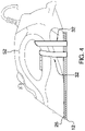
FIG. 4 is a side in-use view of an embodiment of the disclosure.
DETAILED DESCRIPTION OF THE INVENTION
With reference now to the drawings, and in particular to FIGS. 1 through 4 thereof, a new hot object protective covering embodying the principles and concepts of an embodiment of the disclosure and generally designated by the reference numeral 10 will be described.
As best illustrated in FIGS. 1 through 4, the hot iron covering assembly 10 generally comprises a panel 12 that has a top side 14, a bottom side 16 and a perimeter edge 18. The top side 14 has a size and shape of a base 50 of a conventional iron 52. Thus, it would typically include a straight rear edge 20, a pair of lateral edges 22 that come to a pointed front edge 24.
A perimeter lip 26 is attached and is coextensive with the perimeter edge 18. The perimeter lip 26 extends upwardly from the panel 12. The perimeter lip 26 and the panel 12 will typically comprise a unitary structure. The panel 12 comprises a flexible and heat resistant material. One material in particular which may be used is a silicone material. Silicone is heat resistant to a temperature which is much higher than is achieved by a conventional iron.
A securing member 28 is configured to releasably secure the panel 12 to the base 50 of the iron 52. In one embodiment, the securing member 28 includes a magnet 30 that is mounted in the panel 12. The magnet 30 may be positioned in the surface of the top side 14 or may be embedded between the top 14 and bottom 16 sides. The magnet 30 is magnetically attracted to the base 50 of the iron 52. As can be seen in the Figures, the magnet 30 may include multiple magnets 30. In another embodiment, the securing member 28 comprises a strap 32 that is attached to the panel 12. The strap 32 is configured to be extended around the iron 52 to secure the panel 12 to the iron 52. More particularly, the strap 32 may include a first section 34 attached to the panel 12 and a second section 36 attached to the panel 12. The first 34 and second 36 sections are securable to each other a hook and loop coupler 38. The strap 32 may include a pair of straps 32.
In use, after the iron 52 has been used and has an elevated temperature, the panel 12 is placed on the base 50 of the iron 52 to cover the base 50 and prevent the base 50 from inadvertently burning a person or burning/melting another object.
With respect to the above description then, it is to be realized that the optimum dimensional relationships for the parts of an embodiment enabled by the disclosure, to include variations in size, materials, shape, form, function and manner of operation, assembly and use, are deemed readily apparent and obvious to one skilled in the art, and all equivalent relationships to those illustrated in the drawings and described in the specification are intended to be encompassed by an embodiment of the disclosure.
Therefore, the foregoing is considered as illustrative only of the principles of the disclosure. Further, since numerous modifications and changes will readily occur to those skilled in the art, it is not desired to limit the disclosure to the exact construction and operation shown and described, and accordingly, all suitable modifications and equivalents may be resorted to, falling within the scope of the disclosure. In this patent document, the word “comprising” is used in its non-limiting sense to mean that items following the word are included, but items not specifically mentioned are not excluded. A reference to an element by the indefinite article “a” does not exclude the possibility that more than one of the element is present, unless the context clearly requires that there be only one of the elements.