US11296970B2 - Method for detecting a disruption in a vehicle's communication system by checking for abnormalities in communication - Google Patents
Method for detecting a disruption in a vehicle's communication system by checking for abnormalities in communication Download PDFInfo
- Publication number
- US11296970B2 US11296970B2 US16/619,374 US201816619374A US11296970B2 US 11296970 B2 US11296970 B2 US 11296970B2 US 201816619374 A US201816619374 A US 201816619374A US 11296970 B2 US11296970 B2 US 11296970B2
- Authority
- US
- United States
- Prior art keywords
- message
- anomaly
- detecting
- signal
- identifier
- Prior art date
- Legal status (The legal status is an assumption and is not a legal conclusion. Google has not performed a legal analysis and makes no representation as to the accuracy of the status listed.)
- Active, expires
Links
Images


Classifications
-
- H—ELECTRICITY
- H04—ELECTRIC COMMUNICATION TECHNIQUE
- H04L—TRANSMISSION OF DIGITAL INFORMATION, e.g. TELEGRAPHIC COMMUNICATION
- H04L43/00—Arrangements for monitoring or testing data switching networks
- H04L43/50—Testing arrangements
-
- G—PHYSICS
- G06—COMPUTING OR CALCULATING; COUNTING
- G06F—ELECTRIC DIGITAL DATA PROCESSING
- G06F11/00—Error detection; Error correction; Monitoring
- G06F11/07—Responding to the occurrence of a fault, e.g. fault tolerance
- G06F11/0703—Error or fault processing not based on redundancy, i.e. by taking additional measures to deal with the error or fault not making use of redundancy in operation, in hardware, or in data representation
- G06F11/0706—Error or fault processing not based on redundancy, i.e. by taking additional measures to deal with the error or fault not making use of redundancy in operation, in hardware, or in data representation the processing taking place on a specific hardware platform or in a specific software environment
- G06F11/0736—Error or fault processing not based on redundancy, i.e. by taking additional measures to deal with the error or fault not making use of redundancy in operation, in hardware, or in data representation the processing taking place on a specific hardware platform or in a specific software environment in functional embedded systems, i.e. in a data processing system designed as a combination of hardware and software dedicated to performing a certain function
- G06F11/0739—Error or fault processing not based on redundancy, i.e. by taking additional measures to deal with the error or fault not making use of redundancy in operation, in hardware, or in data representation the processing taking place on a specific hardware platform or in a specific software environment in functional embedded systems, i.e. in a data processing system designed as a combination of hardware and software dedicated to performing a certain function in a data processing system embedded in automotive or aircraft systems
-
- G—PHYSICS
- G06—COMPUTING OR CALCULATING; COUNTING
- G06F—ELECTRIC DIGITAL DATA PROCESSING
- G06F11/00—Error detection; Error correction; Monitoring
- G06F11/07—Responding to the occurrence of a fault, e.g. fault tolerance
- G06F11/0703—Error or fault processing not based on redundancy, i.e. by taking additional measures to deal with the error or fault not making use of redundancy in operation, in hardware, or in data representation
- G06F11/0751—Error or fault detection not based on redundancy
- G06F11/0754—Error or fault detection not based on redundancy by exceeding limits
-
- G—PHYSICS
- G06—COMPUTING OR CALCULATING; COUNTING
- G06F—ELECTRIC DIGITAL DATA PROCESSING
- G06F11/00—Error detection; Error correction; Monitoring
- G06F11/07—Responding to the occurrence of a fault, e.g. fault tolerance
- G06F11/0703—Error or fault processing not based on redundancy, i.e. by taking additional measures to deal with the error or fault not making use of redundancy in operation, in hardware, or in data representation
- G06F11/0751—Error or fault detection not based on redundancy
- G06F11/0763—Error or fault detection not based on redundancy by bit configuration check, e.g. of formats or tags
-
- G—PHYSICS
- G06—COMPUTING OR CALCULATING; COUNTING
- G06F—ELECTRIC DIGITAL DATA PROCESSING
- G06F11/00—Error detection; Error correction; Monitoring
- G06F11/22—Detection or location of defective computer hardware by testing during standby operation or during idle time, e.g. start-up testing
-
- G—PHYSICS
- G06—COMPUTING OR CALCULATING; COUNTING
- G06F—ELECTRIC DIGITAL DATA PROCESSING
- G06F11/00—Error detection; Error correction; Monitoring
- G06F11/22—Detection or location of defective computer hardware by testing during standby operation or during idle time, e.g. start-up testing
- G06F11/2289—Detection or location of defective computer hardware by testing during standby operation or during idle time, e.g. start-up testing by configuration test
-
- G—PHYSICS
- G06—COMPUTING OR CALCULATING; COUNTING
- G06F—ELECTRIC DIGITAL DATA PROCESSING
- G06F11/00—Error detection; Error correction; Monitoring
- G06F11/30—Monitoring
- G06F11/3003—Monitoring arrangements specially adapted to the computing system or computing system component being monitored
- G06F11/3013—Monitoring arrangements specially adapted to the computing system or computing system component being monitored where the computing system is an embedded system, i.e. a combination of hardware and software dedicated to perform a certain function in mobile devices, printers, automotive or aircraft systems
-
- G—PHYSICS
- G06—COMPUTING OR CALCULATING; COUNTING
- G06F—ELECTRIC DIGITAL DATA PROCESSING
- G06F11/00—Error detection; Error correction; Monitoring
- G06F11/30—Monitoring
- G06F11/3003—Monitoring arrangements specially adapted to the computing system or computing system component being monitored
- G06F11/3027—Monitoring arrangements specially adapted to the computing system or computing system component being monitored where the computing system component is a bus
-
- G—PHYSICS
- G06—COMPUTING OR CALCULATING; COUNTING
- G06F—ELECTRIC DIGITAL DATA PROCESSING
- G06F11/00—Error detection; Error correction; Monitoring
- G06F11/30—Monitoring
- G06F11/3051—Monitoring arrangements for monitoring the configuration of the computing system or of the computing system component, e.g. monitoring the presence of processing resources, peripherals, I/O links, software programs
-
- G—PHYSICS
- G06—COMPUTING OR CALCULATING; COUNTING
- G06F—ELECTRIC DIGITAL DATA PROCESSING
- G06F21/00—Security arrangements for protecting computers, components thereof, programs or data against unauthorised activity
- G06F21/50—Monitoring users, programs or devices to maintain the integrity of platforms, e.g. of processors, firmware or operating systems
- G06F21/55—Detecting local intrusion or implementing counter-measures
- G06F21/554—Detecting local intrusion or implementing counter-measures involving event detection and direct action
-
- G—PHYSICS
- G06—COMPUTING OR CALCULATING; COUNTING
- G06F—ELECTRIC DIGITAL DATA PROCESSING
- G06F21/00—Security arrangements for protecting computers, components thereof, programs or data against unauthorised activity
- G06F21/70—Protecting specific internal or peripheral components, in which the protection of a component leads to protection of the entire computer
- G06F21/82—Protecting input, output or interconnection devices
- G06F21/85—Protecting input, output or interconnection devices interconnection devices, e.g. bus-connected or in-line devices
-
- H—ELECTRICITY
- H04—ELECTRIC COMMUNICATION TECHNIQUE
- H04L—TRANSMISSION OF DIGITAL INFORMATION, e.g. TELEGRAPHIC COMMUNICATION
- H04L43/00—Arrangements for monitoring or testing data switching networks
- H04L43/08—Monitoring or testing based on specific metrics, e.g. QoS, energy consumption or environmental parameters
- H04L43/0823—Errors, e.g. transmission errors
-
- H—ELECTRICITY
- H04—ELECTRIC COMMUNICATION TECHNIQUE
- H04L—TRANSMISSION OF DIGITAL INFORMATION, e.g. TELEGRAPHIC COMMUNICATION
- H04L63/00—Network architectures or network communication protocols for network security
- H04L63/14—Network architectures or network communication protocols for network security for detecting or protecting against malicious traffic
- H04L63/1408—Network architectures or network communication protocols for network security for detecting or protecting against malicious traffic by monitoring network traffic
- H04L63/1425—Traffic logging, e.g. anomaly detection
-
- H—ELECTRICITY
- H04—ELECTRIC COMMUNICATION TECHNIQUE
- H04L—TRANSMISSION OF DIGITAL INFORMATION, e.g. TELEGRAPHIC COMMUNICATION
- H04L43/00—Arrangements for monitoring or testing data switching networks
- H04L43/02—Capturing of monitoring data
- H04L43/026—Capturing of monitoring data using flow identification
Definitions
- Embodiments relate to detecting possible intrusions and disruptions of a vehicle's communication system.
- Modern vehicles are equipped with numerous computers and electrical components that control various vehicle systems. These computers and components communicate by sending and receiving messages to and from each other.
- the messages that computers and components send and receive include a message identifier followed by a plurality of signals. It is possible to change a vehicle's behavior by disrupting communication between computers and electrical components in the vehicle. With the increased reliance on and use of computer-controlled systems comes the risk of messages and signals being falsely transmitted due to anomalies caused by unexpected vehicle behavior or attacks from outside sources. An intrusion detection system can be used to detect these potential anomalies. The undesired outcomes resulting from messages being improperly transmitted include driver annoyance, driver distraction, or changes in vehicle behavior.
- Embodiments provide, among other things, a system for detecting a disruption in a communication system of a vehicle.
- the system includes a vehicle bus and an electronic processor.
- the electronic processor is configured to receive a message, from a vehicle bus.
- the message has a format and a plurality of signals.
- the electronic processor is configured to detect anomalies in a bus identifier, the message format, a time the message is received, and a signal parameter of a signal of the plurality of signals.
- the electronic processor is also configured to generate an error if an anomaly is detected in the message format, an anomaly is detected in the time the message is received, or an anomaly is detected in the signal parameter of the signal of the plurality of signals.
- Another embodiment provides a method for detecting a disruption in a communication system of a vehicle.
- the method includes receiving, with an electronic processor, a message from a vehicle bus.
- the message received from the vehicle bus has a format and plurality of signals.
- the method also includes testing the message, with the electronic processor, by detecting an anomaly in a bus identifier, detecting an anomaly in the format of the message, detecting an anomaly in a time a message is received and detecting an anomaly in a signal parameter of a signal of the plurality of signals.
- the method also includes generating an error if the anomaly in the format of the message, the anomaly in the time the message is received, or the anomaly in the signal parameter of the signal of the plurality of signals is detected.
- FIG. 1 is a simplified diagram of a vehicle including a communication system.
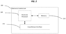
- FIG. 2 is a diagram of an electronic control unit configured to receive and analyze messages.
- FIG. 3 is a flowchart of a method for determining if a communication system (for example, the system of FIG. 1 ) has been compromised (for example, hacked).
- FIG. 4 is a flowchart of a method for checking a bus identifier of a message.
- FIG. 5 is a flowchart of a method for checking that an identifier of a message is known.
- FIG. 6 is a flowchart of a method for checking that a length of a message is correct.
- FIG. 7 is a flowchart of a method for checking that reserved bits of a message are not being used.
- FIG. 8 is a flowchart of a method for checking that messages are being received at the correct time and rate.
- FIG. 9 is a flowchart of a method for checking signal parameters of signals included in a message.
- a plurality of hardware and software based devices may be used to implement various embodiments.
- embodiments may include hardware, software, and electronic components or modules that, for purposes of discussion, may be illustrated and described as if the majority of the components were implemented solely in hardware.
- the electronic based aspects of the invention may be implemented in software (for example, stored on non-transitory computer-readable medium) executable by one or more processors.
- control units” and “controllers” described in the specification can include one or more electronic processors, one or more memory modules including non-transitory computer-readable medium, one or more input/output interfaces, one or more application specific integrated circuits (ASICs), and various connections (for example, a system bus) connecting the various components.
- ASICs application specific integrated circuits
- FIG. 1 illustrates a communication system 100 of a vehicle 105 .
- the vehicle 105 although illustrated as a four-wheeled vehicle, may encompass various types and designs of vehicles.
- the vehicle 105 may be an automobile, a motorcycle, a truck, a bus, a semi-tractor, and others.
- the communication system 100 allows several systems to communicate with each other by sending messages to each other via various wired or wireless connections. Examples of systems which communicate with each other are an engine control system 115 , a motion control system 120 , a transmission control system 125 , a brake control system 130 , and the instrument panel display system 135 . These systems may be of various constructions and may use various communication types and protocols.
- systems which communicate with each other are communicatively coupled via a shared communication link such as a vehicle communication bus (vehicle bus) 140 (for example, a controller area network (CAN) bus) or a wireless vehicle network.
- vehicle bus vehicle bus
- CAN controller area network
- Each of the above-listed systems interacting with each other over the communication system 100 may include dedicated processing circuitry including an electronic control unit for receiving, processing, and transmitting data associated with the functions of each system.
- the engine control system 115 may include an electronic control unit that receives messages, checks that there are no potentially harmful anomalies associated with the received messages, and sends messages.
- FIG. 1 provides but one example of the components and connections of the communication system 100 . It should be understood that these components and connections may be constructed in ways other than those illustrated and described herein.
- FIG. 2 is a block diagram of an electronic control unit 200 of the communication system 100 .
- the electronic control unit 200 includes a plurality of electrical and electronic components that provide power, operation control, and protection to the components and modules within the electronic control unit 200 .
- the electronic control unit 200 includes, among other things, an electronic processor 205 (such as a programmable electronic microprocessor, microcontroller, or similar device), a memory 210 (for example, non-transitory, machine readable memory), and an input/output interface 215 . It should be understood that the electronic control unit 200 is illustrated in FIG. 2 as having a single input/output interface 215 purely for illustrative purposes.
- the electronic control unit 200 may have any number of input/output interfaces and the single input/output interface 215 illustrated herein should not be considered in any way limiting.
- the electronic processor 205 is communicatively connected to the memory 210 and the input/output interface 215 .
- the electronic processor 205 in coordination with the memory 210 and the input/output interface 215 , is configured to implement, among other things, the methods described herein.
- the electronic control unit 200 may be implemented in several independent controllers (for example, programmable electronic control units) each configured to perform specific functions or sub-functions. Additionally, the electronic control unit 200 may contain sub-modules that include additional electronic processors, memory, or application specific integrated circuits (ASICs) for handling input/output functions and application of the methods listed below. In other embodiments, the electronic control unit 200 includes additional, fewer, or different components.
- controllers for example, programmable electronic control units
- ASICs application specific integrated circuits
- FIG. 3 illustrates an example method 300 for determining if the communication system 100 is compromised.
- a bus identifier of a bus for example, the vehicle bus 140
- the format of the message is analyzed.
- the format of the message includes, for example, a message identifier, a length of the message, and reserved bits of the message.
- the time that the message is received is also analyzed.
- the message identifier is analyzed first (block 315 ). If the message identifier is known (no anomaly is found in the message identifier (block 320 )), the length of the message is analyzed (block 325 ), the reserved bits of the message are analyzed (block 330 ), the rate that messages are received is analyzed (block 335 ) and signal parameters of one or more signals included in the message are analyzed (block 340 ). After completing the analysis of the message, the method 300 waits for the electronic control unit 200 to receive a new message (block 302 ). In some embodiments, the electronic processor 205 may perform tests additional to the tests described as being performed in the method 300 .
- the electronic processor 205 may analyze the message in fewer steps than described in the method 300 .
- the number of tests that the electronic processor 205 performs on a message may depend on the results of the tests that the electronic processor 205 has performed on the message.
- Each of the analysis steps or tests of the method 300 are described in further detail below.
- FIG. 4 illustrates an example method 400 for checking the bus identifier associated with a message received by the electronic processor 205 .
- the bus identifier associated with the bus that delivered the message is determined (block 402 ).
- the bus identifier is extracted from the message.
- the bus identifier is determined based on which input/output interface (assuming that the electronic control unit 200 has multiple input/output interfaces similar to the input/output interface 215 ) receives the message and sends the message to the electronic processor 205 .
- the electronic processor 205 searches one or more tables for the determined bus identifier (block 405 ). Each table is associated with a viable bus identifier (for example a CAN bus identifier).
- the electronic processor 205 if the electronic processor 205 does not find a table associated with the determined bus identifier, the electronic processor 205 aborts testing the message and aborts the execution of the message (block 415 ). If the electronic processor 205 finds a table associated with the determined bus identifier, the electronic processor 205 continues to analyze the message (block 420 ).
- FIG. 5 illustrates an example method 500 for checking the message identifier of the received message.
- the message identifier is extracted from the message (block 502 ).
- the electronic processor 205 searches a table for the message identifier of the message (block 505 ).
- the table contains valid message identifiers for the bus identifier of the message.
- the electronic processor 205 if the electronic processor 205 does not find the message identifier of the message in the table containing valid message identifiers for the bus identifier of the message, the electronic processor 205 generates an error, stops testing the message, and aborts the execution of the message (block 515 ). If the electronic processor 205 finds the message identifier of the message in the table, the electronic processor 205 continues to analyze the message (block 520 ).
- FIG. 6 illustrates an example method 600 for checking the length of the received message.
- a predetermined requirement for valid message length is stored in the memory 210 .
- the predetermined requirement for valid message length may be a minimum message length, a maximum message length, or other message length.
- the electronic processor 205 extracts the length of the message (for example, the data length code (DLC) of the message) (block 602 ) and compares the length of the message to the predetermined requirement for valid message length stored in the memory 210 (block 605 ). If the length of the message does not meet the predetermined requirement for valid message length (block 610 ), the electronic processor 205 generates an error (block 615 ) and, in some embodiments, continues to test the message. If the length of the message meets the predetermined requirement for valid message length (block 610 ), the electronic processor 205 continues to test the message (block 620 ).
- DLC data length code
- FIG. 7 illustrates an example method 700 for checking that reserved bits of the message are valid.
- Reserved bits are defined as bits that should not be used or are not assigned to a signal.
- the electronic processor 205 extracts data, including the reserved bits, from the message (block 702 ) and checks that the reserved bits are not being used (block 705 ). If the reserved bits of the message are being used (block 710 ), the electronic processor 205 generates an error (block 715 ) and, in some embodiments, continues to test the message. If the received message's reserved bits are not being used (block 710 ), the electronic processor 205 continues to test the message (block 720 ).
- FIG. 8 illustrates an example method 800 for checking that messages are being received at an appropriate rate and time (detecting anomalies in a time that a message is received).
- the electronic processor 205 calculates an amount of time that has elapsed (a time difference) between receiving a current message and receiving a previous message with the same message identifier as the current message (block 802 ). For every message identifier, the electronic processor 205 has (stored in the memory 210 ) an amount of time which should have elapsed between messages (a previously established time difference). The electronic processor 205 checks that the amount of time that has elapsed is greater than or equal to the amount of time which should have elapsed (block 805 ).
- the electronic processor 205 If the amount of time that has elapsed is not greater than or equal to (or the amount of time that has elapsed is less than) the amount of time which should have elapsed, the electronic processor 205 generates an error (block 810 ) and, in some embodiments, continues to test the message. If the electronic processor 205 determines the rate that messages are received is too fast (block 820 ) (for example, by determining if the time difference is above a first predetermined threshold value), the electronic processor 205 generates an error (block 825 ) and, in some embodiments, continues to test the message.
- the electronic processor 205 determines the rate that messages are received is too slow (block 830 ) (for example, by determining if the time difference is below a second predetermined threshold value), the electronic processor 205 generates an error (block 835 ) and, in some embodiments, continues to test the message.
- FIG. 9 illustrates an example method 900 for checking the signal parameters of a signal.
- the electronic processor 205 checks that the signal is within a predetermined allowable range (block 910 ).
- the allowable range is, for example, a range of linear values. If the signal is not within the predetermined allowable range, the electronic processor 205 generates an error (block 915 ).
- the electronic processor 205 may check that the signal is not within a predetermined unallowable range.
- the unallowable range is, for example, a range of linear values. If the signal is within the predetermined unallowable range, the electronic processor 205 generates an error (block 915 ).
- a table of valid signal values is stored in memory 210 .
- the electronic processor 205 searches the table for the signal value of the signal (block 925 ). If the signal value of the signal is not in the table, the electronic processor 205 generates an error (block 930 ). In some embodiments, a table of invalid signal values is stored in memory 210 . The electronic processor 205 searches the table for the signal value of the signal. If the signal value of the signal is in the table, the electronic processor 205 generates an error. The electronic processor 205 also checks if the signal is a counter value or, more simply, a counter. If the signal is a counter, the electronic processor 205 checks if the counter has increased or decreased by one (or been updated correctly) (block 940 ). If the counter has increased or decreased by more than one, the electronic processor 205 generates an error (block 945 ). In some embodiments, the electronic processor 205 also generates an error if the counter that is supposed to continually increase (or decrease) has not increased (or decreased).
- the electronic processor 205 also checks that the value of the signal changes at an allowable rate (block 955 ).
- Checking the rate at which the value of the signal changes includes a plurality of tests. For example, a test included in the plurality of tests for checking the rate at which the value of the signal changes checks if the value of the signal changes by more than a predetermined threshold between two messages received consecutively. If the value of the signal changes by more than the predetermined threshold, the electronic processor 205 generates an error (block 960 ). Another example of a test included in the plurality of tests compares, to a predetermined threshold, an amount the signal has changed from the beginning of a predetermined time period to the end of the predetermined time period.
- the electronic processor 205 will compare the value of 5 to the predetermined threshold. If the value of the signal changes by more than the predetermined threshold in the predetermined time period, the electronic processor 205 generates an error (block 960 ).
- a test included in the plurality of tests checks if fluctuations of the signal value within a predetermined time period are greater than a predetermined amount. In some embodiments, the fluctuations of the signal value are the absolute value of the sum of delta values of the signal over the predetermined period of time.
- the absolute value of the sum of the delta values of the signal is twenty-five. If the value of the signal fluctuates by more than the predetermined amount in the predetermined time period, the electronic processor 205 generates an error (block 960 ).
Landscapes
- Engineering & Computer Science (AREA)
- Theoretical Computer Science (AREA)
- General Engineering & Computer Science (AREA)
- Physics & Mathematics (AREA)
- General Physics & Mathematics (AREA)
- Quality & Reliability (AREA)
- Computing Systems (AREA)
- Computer Hardware Design (AREA)
- Computer Security & Cryptography (AREA)
- Signal Processing (AREA)
- Computer Networks & Wireless Communication (AREA)
- Software Systems (AREA)
- Mathematical Physics (AREA)
- Environmental & Geological Engineering (AREA)
- Small-Scale Networks (AREA)
Abstract
Description
Claims (20)
Priority Applications (1)
| Application Number | Priority Date | Filing Date | Title |
|---|---|---|---|
| US16/619,374 US11296970B2 (en) | 2017-06-23 | 2018-04-11 | Method for detecting a disruption in a vehicle's communication system by checking for abnormalities in communication |
Applications Claiming Priority (3)
| Application Number | Priority Date | Filing Date | Title |
|---|---|---|---|
| US201762524068P | 2017-06-23 | 2017-06-23 | |
| US16/619,374 US11296970B2 (en) | 2017-06-23 | 2018-04-11 | Method for detecting a disruption in a vehicle's communication system by checking for abnormalities in communication |
| PCT/EP2018/059212 WO2018233889A1 (en) | 2017-06-23 | 2018-04-11 | METHOD FOR DETECTING AN INTERRUPTION IN A COMMUNICATION SYSTEM OF A VEHICLE BY VERIFYING ANOMALIES DURING COMMUNICATION |
Publications (2)
| Publication Number | Publication Date |
|---|---|
| US20200162361A1 US20200162361A1 (en) | 2020-05-21 |
| US11296970B2 true US11296970B2 (en) | 2022-04-05 |
Family
ID=61972120
Family Applications (1)
| Application Number | Title | Priority Date | Filing Date |
|---|---|---|---|
| US16/619,374 Active 2038-04-16 US11296970B2 (en) | 2017-06-23 | 2018-04-11 | Method for detecting a disruption in a vehicle's communication system by checking for abnormalities in communication |
Country Status (6)
| Country | Link |
|---|---|
| US (1) | US11296970B2 (en) |
| EP (1) | EP3642715B1 (en) |
| JP (1) | JP6931094B2 (en) |
| KR (1) | KR102505993B1 (en) |
| CN (1) | CN110753912A (en) |
| WO (1) | WO2018233889A1 (en) |
Cited By (1)
| Publication number | Priority date | Publication date | Assignee | Title |
|---|---|---|---|---|
| US20220006821A1 (en) * | 2018-10-11 | 2022-01-06 | Nippon Telegraph And Telephone Corporation | Information processing apparatus, data analysis method and program |
Families Citing this family (5)
| Publication number | Priority date | Publication date | Assignee | Title |
|---|---|---|---|---|
| US11201884B2 (en) * | 2018-11-30 | 2021-12-14 | Raytheon Company | Bus monitoring system for detecting anomalies indicative of malfunctions or cyber-attacks |
| CN111891134B (en) * | 2019-05-06 | 2022-09-30 | 北京百度网讯科技有限公司 | Automatic driving processing system, system on chip and method for monitoring processing module |
| JP7759811B2 (en) * | 2022-01-18 | 2025-10-24 | 本田技研工業株式会社 | Inspection device and inspection method |
| DE102022207919A1 (en) * | 2022-08-01 | 2024-02-01 | Robert Bosch Gesellschaft mit beschränkter Haftung | Subscriber station for a serial bus system and method for communication in a serial bus system |
| US12613761B1 (en) * | 2022-10-14 | 2026-04-28 | Blackrock Finance, Inc. | Data science anomaly detection |
Citations (29)
| Publication number | Priority date | Publication date | Assignee | Title |
|---|---|---|---|---|
| US20050283831A1 (en) | 2004-06-21 | 2005-12-22 | Lg N-Sys Inc. | Security system and method using server security solution and network security solution |
| US20060036727A1 (en) | 2004-08-13 | 2006-02-16 | Sipera Systems, Inc. | System and method for detecting and preventing denial of service attacks in a communications system |
| US20060123481A1 (en) | 2004-12-07 | 2006-06-08 | Nortel Networks Limited | Method and apparatus for network immunization |
| JP2007067812A (en) | 2005-08-31 | 2007-03-15 | Fujitsu Ten Ltd | Frame monitoring device |
| US20080178294A1 (en) | 2006-11-27 | 2008-07-24 | Guoning Hu | Wireless intrusion prevention system and method |
| US20100318794A1 (en) | 2009-06-11 | 2010-12-16 | Panasonic Avionics Corporation | System and Method for Providing Security Aboard a Moving Platform |
| US20120210178A1 (en) | 2009-06-17 | 2012-08-16 | Robert Bosch Gmbh | Method for Operating a Bus System, in particular a CAN Bus |
| US20130212680A1 (en) | 2012-01-12 | 2013-08-15 | Arxceo Corporation | Methods and systems for protecting network devices from intrusion |
| WO2014061021A1 (en) | 2012-10-17 | 2014-04-24 | Tower-Sec Ltd. | A device for detection and prevention of an attack on a vehicle |
| US20140165191A1 (en) | 2012-12-12 | 2014-06-12 | Hyundai Motor Company | Apparatus and method for detecting in-vehicle network attack |
| DE102012224234A1 (en) | 2012-12-21 | 2014-06-26 | Continental Teves Ag & Co. Ohg | Method for controlling data frames with redundant identifier on e.g. controller area network bus, involves initiating termination of transmission of data frames, if identifier of frames is matched with identifier of second bus device |
| WO2014115455A1 (en) | 2013-01-28 | 2014-07-31 | 日立オートモティブシステムズ株式会社 | Network device and data sending and receiving system |
| JP2014236248A (en) | 2013-05-30 | 2014-12-15 | 日立オートモティブシステムズ株式会社 | Electronic control device and electronic control system |
| US8955130B1 (en) | 2014-04-10 | 2015-02-10 | Zephyr Technology Co., Limited | Method for protecting vehicle data transmission system from intrusions |
| US20150113638A1 (en) | 2013-10-23 | 2015-04-23 | Christopher Valasek | Electronic system for detecting and preventing compromise of vehicle electrical and control systems |
| US20150150124A1 (en) | 2013-11-27 | 2015-05-28 | Cisco Technology, Inc. | Cloud-assisted threat defense for connected vehicles |
| US20150172306A1 (en) | 2013-12-13 | 2015-06-18 | Hyundai Motor Company | Method and apparatus for enhancing security in an in-vehicle communication network |
| US20150191151A1 (en) | 2014-01-06 | 2015-07-09 | Argus Cyber Security Ltd. | Detective watchman |
| WO2015159486A1 (en) | 2014-04-17 | 2015-10-22 | パナソニック インテレクチュアル プロパティ コーポレーション オブ アメリカ | Vehicle-mounted network system, invalidity detection electronic control unit, and invalidity detection method |
| WO2016046819A1 (en) | 2014-09-25 | 2016-03-31 | Tower-Sec Ltd. | Vehicle correlation system for cyber attacks detection and method thereof |
| JP2016134913A (en) | 2015-01-20 | 2016-07-25 | パナソニック インテレクチュアル プロパティ コーポレーション オブ アメリカPanasonic Intellectual Property Corporation of America | Unauthorized frame handling method, unauthorized detection electronic control unit and on-vehicle network system |
| WO2016151566A1 (en) | 2015-03-26 | 2016-09-29 | Tower-Sec Ltd | Security system and methods for identification of in-vehicle attack originator |
| EP3096257A1 (en) | 2015-05-22 | 2016-11-23 | Nxp B.V. | In-vehicle network (ivn) device and method for operating an ivn device |
| US20160359893A1 (en) * | 2014-12-01 | 2016-12-08 | Panasonic Intellectual Property Corporation Of America | Anomaly detection electronic control unit, onboard network system, and anomaly detection method |
| US20160381068A1 (en) | 2015-06-29 | 2016-12-29 | Argus Cyber Security Ltd. | System and method for time based anomaly detection in an in-vehicle communication network |
| US20160381055A1 (en) | 2015-06-29 | 2016-12-29 | Argus Cyber Security Ltd. | System and method for providing security to a communication network |
| US20170013005A1 (en) | 2015-06-29 | 2017-01-12 | Argus Cyber Security Ltd. | System and method for consistency based anomaly detection in an in-vehicle communication network |
| WO2017021970A1 (en) | 2015-08-06 | 2017-02-09 | Tower-Sec Ltd | Means and methods for regulating can communication |
| US20180152472A1 (en) | 2015-09-29 | 2018-05-31 | Panasonic Intellectual Property Corporation Of America | Invalidity detection electronic control unit, in-vehicle network system, and communication method |
Family Cites Families (3)
| Publication number | Priority date | Publication date | Assignee | Title |
|---|---|---|---|---|
| CN104320295B (en) * | 2014-10-08 | 2018-05-29 | 清华大学 | CAN message method for detecting abnormality and system |
| JP6573819B2 (en) * | 2015-01-20 | 2019-09-11 | パナソニック インテレクチュアル プロパティ コーポレーション オブ アメリカPanasonic Intellectual Property Corporation of America | Fraud detection rule update method, fraud detection electronic control unit and in-vehicle network system |
| US9531750B2 (en) * | 2015-05-19 | 2016-12-27 | Ford Global Technologies, Llc | Spoofing detection |
-
2018
- 2018-04-11 CN CN201880041518.6A patent/CN110753912A/en active Pending
- 2018-04-11 EP EP18717583.1A patent/EP3642715B1/en active Active
- 2018-04-11 US US16/619,374 patent/US11296970B2/en active Active
- 2018-04-11 JP JP2019570917A patent/JP6931094B2/en active Active
- 2018-04-11 WO PCT/EP2018/059212 patent/WO2018233889A1/en not_active Ceased
- 2018-04-11 KR KR1020197037784A patent/KR102505993B1/en active Active
Patent Citations (36)
| Publication number | Priority date | Publication date | Assignee | Title |
|---|---|---|---|---|
| US20050283831A1 (en) | 2004-06-21 | 2005-12-22 | Lg N-Sys Inc. | Security system and method using server security solution and network security solution |
| US20060036727A1 (en) | 2004-08-13 | 2006-02-16 | Sipera Systems, Inc. | System and method for detecting and preventing denial of service attacks in a communications system |
| US20060123481A1 (en) | 2004-12-07 | 2006-06-08 | Nortel Networks Limited | Method and apparatus for network immunization |
| JP2007067812A (en) | 2005-08-31 | 2007-03-15 | Fujitsu Ten Ltd | Frame monitoring device |
| US20080178294A1 (en) | 2006-11-27 | 2008-07-24 | Guoning Hu | Wireless intrusion prevention system and method |
| US20100318794A1 (en) | 2009-06-11 | 2010-12-16 | Panasonic Avionics Corporation | System and Method for Providing Security Aboard a Moving Platform |
| US20120210178A1 (en) | 2009-06-17 | 2012-08-16 | Robert Bosch Gmbh | Method for Operating a Bus System, in particular a CAN Bus |
| US20130212680A1 (en) | 2012-01-12 | 2013-08-15 | Arxceo Corporation | Methods and systems for protecting network devices from intrusion |
| WO2014061021A1 (en) | 2012-10-17 | 2014-04-24 | Tower-Sec Ltd. | A device for detection and prevention of an attack on a vehicle |
| US9560071B2 (en) | 2012-10-17 | 2017-01-31 | Tower-Sec Ltd. | Device for detection and prevention of an attack on a vehicle |
| US20140165191A1 (en) | 2012-12-12 | 2014-06-12 | Hyundai Motor Company | Apparatus and method for detecting in-vehicle network attack |
| DE102012224234A1 (en) | 2012-12-21 | 2014-06-26 | Continental Teves Ag & Co. Ohg | Method for controlling data frames with redundant identifier on e.g. controller area network bus, involves initiating termination of transmission of data frames, if identifier of frames is matched with identifier of second bus device |
| WO2014115455A1 (en) | 2013-01-28 | 2014-07-31 | 日立オートモティブシステムズ株式会社 | Network device and data sending and receiving system |
| US9794286B2 (en) | 2013-01-28 | 2017-10-17 | Hitachi Automotive Systems, Ltd. | Network device, and data sending and receiving system |
| JP2014236248A (en) | 2013-05-30 | 2014-12-15 | 日立オートモティブシステムズ株式会社 | Electronic control device and electronic control system |
| US20150113638A1 (en) | 2013-10-23 | 2015-04-23 | Christopher Valasek | Electronic system for detecting and preventing compromise of vehicle electrical and control systems |
| US20150150124A1 (en) | 2013-11-27 | 2015-05-28 | Cisco Technology, Inc. | Cloud-assisted threat defense for connected vehicles |
| US20150172306A1 (en) | 2013-12-13 | 2015-06-18 | Hyundai Motor Company | Method and apparatus for enhancing security in an in-vehicle communication network |
| US20150191136A1 (en) | 2014-01-06 | 2015-07-09 | Argus Cyber Security Ltd. | Hosted watchman |
| US20150191151A1 (en) | 2014-01-06 | 2015-07-09 | Argus Cyber Security Ltd. | Detective watchman |
| US20150191135A1 (en) | 2014-01-06 | 2015-07-09 | Argus Cyber Security Ltd. | Bus watchman |
| US8955130B1 (en) | 2014-04-10 | 2015-02-10 | Zephyr Technology Co., Limited | Method for protecting vehicle data transmission system from intrusions |
| WO2015159486A1 (en) | 2014-04-17 | 2015-10-22 | パナソニック インテレクチュアル プロパティ コーポレーション オブ アメリカ | Vehicle-mounted network system, invalidity detection electronic control unit, and invalidity detection method |
| WO2016046819A1 (en) | 2014-09-25 | 2016-03-31 | Tower-Sec Ltd. | Vehicle correlation system for cyber attacks detection and method thereof |
| US20160359893A1 (en) * | 2014-12-01 | 2016-12-08 | Panasonic Intellectual Property Corporation Of America | Anomaly detection electronic control unit, onboard network system, and anomaly detection method |
| JP2016134913A (en) | 2015-01-20 | 2016-07-25 | パナソニック インテレクチュアル プロパティ コーポレーション オブ アメリカPanasonic Intellectual Property Corporation of America | Unauthorized frame handling method, unauthorized detection electronic control unit and on-vehicle network system |
| WO2016151566A1 (en) | 2015-03-26 | 2016-09-29 | Tower-Sec Ltd | Security system and methods for identification of in-vehicle attack originator |
| EP3096257A1 (en) | 2015-05-22 | 2016-11-23 | Nxp B.V. | In-vehicle network (ivn) device and method for operating an ivn device |
| US20160381059A1 (en) | 2015-06-29 | 2016-12-29 | Argus Cyber Security Ltd. | System and method for time based anomaly detection in an in-vehicle communication network |
| US20160381055A1 (en) | 2015-06-29 | 2016-12-29 | Argus Cyber Security Ltd. | System and method for providing security to a communication network |
| EP3113529A1 (en) | 2015-06-29 | 2017-01-04 | Argus Cyber Security Ltd | System and method for time based anomaly detection in an in-vehicle communication network |
| US20170013005A1 (en) | 2015-06-29 | 2017-01-12 | Argus Cyber Security Ltd. | System and method for consistency based anomaly detection in an in-vehicle communication network |
| US20160381067A1 (en) | 2015-06-29 | 2016-12-29 | Argus Cyber Security Ltd. | System and method for content based anomaly detection in an in-vehicle communication network |
| US20160381068A1 (en) | 2015-06-29 | 2016-12-29 | Argus Cyber Security Ltd. | System and method for time based anomaly detection in an in-vehicle communication network |
| WO2017021970A1 (en) | 2015-08-06 | 2017-02-09 | Tower-Sec Ltd | Means and methods for regulating can communication |
| US20180152472A1 (en) | 2015-09-29 | 2018-05-31 | Panasonic Intellectual Property Corporation Of America | Invalidity detection electronic control unit, in-vehicle network system, and communication method |
Non-Patent Citations (2)
| Title |
|---|
| International Search Report and Written Opinion dated Jul. 11, 2018, Appl. No. PCT/EP2018/059212, filed Apr. 11, 2018. |
| Japanese Patent Office Action for Application No. 2019-570917 dated Jan. 25, 2021 (4 pages including machine translation). |
Cited By (2)
| Publication number | Priority date | Publication date | Assignee | Title |
|---|---|---|---|---|
| US20220006821A1 (en) * | 2018-10-11 | 2022-01-06 | Nippon Telegraph And Telephone Corporation | Information processing apparatus, data analysis method and program |
| US11962605B2 (en) * | 2018-10-11 | 2024-04-16 | Nippon Telegraph And Telephone Corporation | Information processing apparatus, data analysis method and program |
Also Published As
| Publication number | Publication date |
|---|---|
| US20200162361A1 (en) | 2020-05-21 |
| KR20200020720A (en) | 2020-02-26 |
| JP2020524951A (en) | 2020-08-20 |
| CN110753912A (en) | 2020-02-04 |
| EP3642715A1 (en) | 2020-04-29 |
| KR102505993B1 (en) | 2023-03-03 |
| JP6931094B2 (en) | 2021-09-01 |
| EP3642715B1 (en) | 2021-04-07 |
| WO2018233889A1 (en) | 2018-12-27 |
Similar Documents
| Publication | Publication Date | Title |
|---|---|---|
| US11296970B2 (en) | Method for detecting a disruption in a vehicle's communication system by checking for abnormalities in communication | |
| KR101564901B1 (en) | Protocol protection | |
| US11032300B2 (en) | Intrusion detection system based on electrical CAN signal for in-vehicle CAN network | |
| US10713106B2 (en) | Communication device, communication method and non-transitory storage medium | |
| CN102933443B (en) | Error detection device and method for dual controller system | |
| US20170134358A1 (en) | Communication system, communication control device, and fraudulent information-transmission preventing method | |
| JP5393932B1 (en) | Data processing apparatus and communication system | |
| US9531750B2 (en) | Spoofing detection | |
| US20200336504A1 (en) | Log generation method, log generation device, and recording medium | |
| US10243941B2 (en) | Need based controller area network bus authentication | |
| CN107306185A (en) | Method and apparatus for avoiding the manipulation to data transfer | |
| GB2592967A (en) | A method for monitoring a network | |
| US11526605B2 (en) | Extraction device, extraction method, recording medium, and detection device | |
| US12141275B2 (en) | Graphical user interface tool for configuring a vehicle's intrusion detection system | |
| US11757745B2 (en) | Gateway apparatus, abnormality monitoring method, and storage medium | |
| US9619310B2 (en) | High speed data transmission methods and systems upon error detection | |
| US20160011932A1 (en) | Method for Monitoring Software in a Road Vehicle | |
| KR20200124470A (en) | Apparatus for gateway of a vehicle, system having the same and method for detect invasion thereof | |
| US12101203B2 (en) | Relay device, communication network system, and communication control method | |
| US11084495B2 (en) | Monitoring apparatus, monitoring method, and program | |
| CN112333038A (en) | Vehicle gateway detection method and device | |
| US11258755B2 (en) | Method and system for processing coherent data |
Legal Events
| Date | Code | Title | Description |
|---|---|---|---|
| FEPP | Fee payment procedure |
Free format text: ENTITY STATUS SET TO UNDISCOUNTED (ORIGINAL EVENT CODE: BIG.); ENTITY STATUS OF PATENT OWNER: LARGE ENTITY |
|
| STPP | Information on status: patent application and granting procedure in general |
Free format text: NON FINAL ACTION MAILED |
|
| STPP | Information on status: patent application and granting procedure in general |
Free format text: RESPONSE TO NON-FINAL OFFICE ACTION ENTERED AND FORWARDED TO EXAMINER |
|
| STPP | Information on status: patent application and granting procedure in general |
Free format text: FINAL REJECTION MAILED |
|
| STCV | Information on status: appeal procedure |
Free format text: NOTICE OF APPEAL FILED |
|
| STCV | Information on status: appeal procedure |
Free format text: APPEAL BRIEF (OR SUPPLEMENTAL BRIEF) ENTERED AND FORWARDED TO EXAMINER |
|
| STPP | Information on status: patent application and granting procedure in general |
Free format text: NOTICE OF ALLOWANCE MAILED -- APPLICATION RECEIVED IN OFFICE OF PUBLICATIONS |
|
| STPP | Information on status: patent application and granting procedure in general |
Free format text: PUBLICATIONS -- ISSUE FEE PAYMENT VERIFIED |
|
| STCF | Information on status: patent grant |
Free format text: PATENTED CASE |
|
| MAFP | Maintenance fee payment |
Free format text: PAYMENT OF MAINTENANCE FEE, 4TH YEAR, LARGE ENTITY (ORIGINAL EVENT CODE: M1551); ENTITY STATUS OF PATENT OWNER: LARGE ENTITY Year of fee payment: 4 |