US11291805B2 - Medical elongated body and medical elongated body set - Google Patents
Medical elongated body and medical elongated body set Download PDFInfo
- Publication number
- US11291805B2 US11291805B2 US16/519,723 US201916519723A US11291805B2 US 11291805 B2 US11291805 B2 US 11291805B2 US 201916519723 A US201916519723 A US 201916519723A US 11291805 B2 US11291805 B2 US 11291805B2
- Authority
- US
- United States
- Prior art keywords
- proximal
- valve body
- marker
- marker portion
- cap member
- Prior art date
- Legal status (The legal status is an assumption and is not a legal conclusion. Google has not performed a legal analysis and makes no representation as to the accuracy of the status listed.)
- Active, expires
Links
Images


Classifications
-
- A—HUMAN NECESSITIES
- A61—MEDICAL OR VETERINARY SCIENCE; HYGIENE
- A61M—DEVICES FOR INTRODUCING MEDIA INTO, OR ONTO, THE BODY; DEVICES FOR TRANSDUCING BODY MEDIA OR FOR TAKING MEDIA FROM THE BODY; DEVICES FOR PRODUCING OR ENDING SLEEP OR STUPOR
- A61M25/00—Catheters; Hollow probes
- A61M25/01—Introducing, guiding, advancing, emplacing or holding catheters
- A61M25/06—Body-piercing guide needles or the like
- A61M25/0662—Guide tubes
-
- A—HUMAN NECESSITIES
- A61—MEDICAL OR VETERINARY SCIENCE; HYGIENE
- A61M—DEVICES FOR INTRODUCING MEDIA INTO, OR ONTO, THE BODY; DEVICES FOR TRANSDUCING BODY MEDIA OR FOR TAKING MEDIA FROM THE BODY; DEVICES FOR PRODUCING OR ENDING SLEEP OR STUPOR
- A61M25/00—Catheters; Hollow probes
- A61M25/01—Introducing, guiding, advancing, emplacing or holding catheters
- A61M25/0105—Steering means as part of the catheter or advancing means; Markers for positioning
- A61M25/0133—Tip steering devices
- A61M25/0138—Tip steering devices having flexible regions as a result of weakened outer material, e.g. slots, slits, cuts, joints or coils
-
- A—HUMAN NECESSITIES
- A61—MEDICAL OR VETERINARY SCIENCE; HYGIENE
- A61M—DEVICES FOR INTRODUCING MEDIA INTO, OR ONTO, THE BODY; DEVICES FOR TRANSDUCING BODY MEDIA OR FOR TAKING MEDIA FROM THE BODY; DEVICES FOR PRODUCING OR ENDING SLEEP OR STUPOR
- A61M25/00—Catheters; Hollow probes
- A61M25/01—Introducing, guiding, advancing, emplacing or holding catheters
- A61M25/02—Holding devices, e.g. on the body
- A61M25/04—Holding devices, e.g. on the body in the body, e.g. expansible
-
- A—HUMAN NECESSITIES
- A61—MEDICAL OR VETERINARY SCIENCE; HYGIENE
- A61M—DEVICES FOR INTRODUCING MEDIA INTO, OR ONTO, THE BODY; DEVICES FOR TRANSDUCING BODY MEDIA OR FOR TAKING MEDIA FROM THE BODY; DEVICES FOR PRODUCING OR ENDING SLEEP OR STUPOR
- A61M39/00—Tubes, tube connectors, tube couplings, valves, access sites or the like, specially adapted for medical use
- A61M39/02—Access sites
- A61M39/06—Haemostasis valves, i.e. gaskets sealing around a needle, catheter or the like, closing on removal thereof
-
- A—HUMAN NECESSITIES
- A61—MEDICAL OR VETERINARY SCIENCE; HYGIENE
- A61M—DEVICES FOR INTRODUCING MEDIA INTO, OR ONTO, THE BODY; DEVICES FOR TRANSDUCING BODY MEDIA OR FOR TAKING MEDIA FROM THE BODY; DEVICES FOR PRODUCING OR ENDING SLEEP OR STUPOR
- A61M25/00—Catheters; Hollow probes
- A61M25/0043—Catheters; Hollow probes characterised by structural features
- A61M2025/0059—Catheters; Hollow probes characterised by structural features having means for preventing the catheter, sheath or lumens from collapsing due to outer forces, e.g. compressing forces, or caused by twisting or kinking
-
- A—HUMAN NECESSITIES
- A61—MEDICAL OR VETERINARY SCIENCE; HYGIENE
- A61M—DEVICES FOR INTRODUCING MEDIA INTO, OR ONTO, THE BODY; DEVICES FOR TRANSDUCING BODY MEDIA OR FOR TAKING MEDIA FROM THE BODY; DEVICES FOR PRODUCING OR ENDING SLEEP OR STUPOR
- A61M25/00—Catheters; Hollow probes
- A61M25/01—Introducing, guiding, advancing, emplacing or holding catheters
- A61M25/02—Holding devices, e.g. on the body
- A61M2025/0246—Holding devices, e.g. on the body fixed on the skin having a cover for covering the holding means
-
- A—HUMAN NECESSITIES
- A61—MEDICAL OR VETERINARY SCIENCE; HYGIENE
- A61M—DEVICES FOR INTRODUCING MEDIA INTO, OR ONTO, THE BODY; DEVICES FOR TRANSDUCING BODY MEDIA OR FOR TAKING MEDIA FROM THE BODY; DEVICES FOR PRODUCING OR ENDING SLEEP OR STUPOR
- A61M25/00—Catheters; Hollow probes
- A61M25/01—Introducing, guiding, advancing, emplacing or holding catheters
- A61M25/02—Holding devices, e.g. on the body
- A61M2025/0293—Catheter, guide wire or the like with means for holding, centering, anchoring or frictionally engaging the device within an artificial lumen, e.g. tube
-
- A—HUMAN NECESSITIES
- A61—MEDICAL OR VETERINARY SCIENCE; HYGIENE
- A61M—DEVICES FOR INTRODUCING MEDIA INTO, OR ONTO, THE BODY; DEVICES FOR TRANSDUCING BODY MEDIA OR FOR TAKING MEDIA FROM THE BODY; DEVICES FOR PRODUCING OR ENDING SLEEP OR STUPOR
- A61M25/00—Catheters; Hollow probes
- A61M25/01—Introducing, guiding, advancing, emplacing or holding catheters
- A61M25/06—Body-piercing guide needles or the like
- A61M25/0662—Guide tubes
- A61M2025/0681—Systems with catheter and outer tubing, e.g. sheath, sleeve or guide tube
-
- A—HUMAN NECESSITIES
- A61—MEDICAL OR VETERINARY SCIENCE; HYGIENE
- A61M—DEVICES FOR INTRODUCING MEDIA INTO, OR ONTO, THE BODY; DEVICES FOR TRANSDUCING BODY MEDIA OR FOR TAKING MEDIA FROM THE BODY; DEVICES FOR PRODUCING OR ENDING SLEEP OR STUPOR
- A61M29/00—Dilators with or without means for introducing media, e.g. remedies
Definitions
- the present invention generally relates to a medical elongated body and a medical elongated body set each having a tubular body insertable into a body lumen.
- a medical elongated body having a tubular body insertable into a body lumen is used when medical devices such as various catheters are percutaneously introduced into a living body.
- the medical elongated body is, for example, an introducer sheath including a tubular body insertable into a body lumen, a hub disposed in the proximal portion of the tubular body, and a valve body disposed in the hub.
- the introducer sheath is percutaneously introduced into the body lumen from the distal side of the tubular body so that an access path connecting the inside of a living body and the outside of the living body is formed.
- a dilator (medical instrument) is inserted into the lumen of the introducer sheath at this time so that the rigidity of the tubular body is enhanced.
- a medical instrument such as a guide wire and a catheter is inserted into the introducer sheath in a state where the distal side of the tubular body is in the body lumen and the proximal side of the tubular body is exposed to the outside of the living body (in a state where the access path connecting the inside of the living body and the outside of the living body is formed).
- Japanese Patent Application Publication No. 2013-208428 discloses a medical elongated body including, for example, a device for guiding a medical instrument to a valve body.
- the number of parts increases by the amount of the device and the structure of the medical elongated body as a whole becomes complicated. Problems arise as a result, including an increase in medical elongated body manufacturing cost.
- the medical elongated body and medical elongated body set disclosed here have a relatively simple structure capable of expediting medical instrument insertion into a tubular body lumen via a valve body.
- a medical elongated body comprises a tubular body insertable into a body lumen of a patient, wherein the tubular body includes a lumen; a hub that includes an internal space communicating with the lumen of the tubular body and disposed in a proximal portion of the tubular body; a valve body disposed in the internal space of the hub and including an insertion portion through which is insertable a medical instrument when the tubular body is positioned in the body lumen of the patient to introduce the medical instrument into the body lumen of the patient; and a cap member attached to the valve body in a manner fixing the valve body in the internal space of the hub.
- the cap member includes a proximal opening portion configured to communicate with the internal space via the insertion portion.
- the cap member also includes a marker portion that guides the medical instrument to the valve body during insertion of the medical instrument into the tubular body, and the marker portion is of a color that is visually distinguishable from a periphery of the marker portion
- a medical elongated body comprises a tubular body insertable into a body lumen of a patient, with the tubular body including a lumen; a hub that includes an internal space communicating with the lumen of the tubular body and disposed in a proximal portion of the tubular body; a valve body disposed in the internal space of the hub and including an insertion portion through which is insertable a medical instrument when the tubular body is positioned in the body lumen of the patient to introduce the medical instrument into the body lumen of the patient; and a cap member attached to the valve body in a manner fixing the valve body in the internal space of the hub.
- the cap member includes a proximal opening portion configured to communicate with the internal space via the insertion portion.
- the valve body including a marker portion that guides the medical instrument to the insertion portion during insertion of the medical instrument into the tubular body, and the marker portion is of a color that is visually distinguishable from a periphery of the marker portion
- a medical elongated body set for achieving the above-described object includes the medical elongated body and a dilator insertable into a lumen of the medical elongated body.
- the medical elongated body is an introducer sheath, and a distal end marker portion is of a color distinguishable from a surrounding is provided in a distal portion of the dilator.
- a medical elongated body comprises: a tubular body possessing a lumen into which a medical instrument is insertable, with the tubular body possessing a proximal portion; a hub connected to the proximal portion of the tubular body, with the hub possessing an internal space communicating with the lumen of the tubular body and also possessing an inner surface and a proximal portion.
- a valve body is disposed in the proximal portion of the hub and covers the internal space so that the internal space is bounded by the valve body and the inner surface of the hub, with the valve body possessing a center and including an insertion portion into which a medical instrument is insertable, and the valve body possessing a proximal surface facing away from the tubular body and a distal surface facing toward the tubular body.
- the valve body includes a proximal surface and a distal surface positioned on opposite surfaces of the valve body, and a cap member is attached to the proximal portion of the hub and is in direct contact with the proximal surface of the valve body.
- the cap member possesses a centrally located proximal opening portion passing through the cap member.
- the insertion portion is exposed in the proximal opening portion of the cap member so that the medical instrument is insertable into the insertion portion of the valve body while passing through the proximal opening portion of the cap member.
- the cap member includes a marker portion that guides the medical instrument to the insertion portion of the valve body during insertion of the medical instrument into the tubular body.
- the insertion portion includes a proximal side slit located on the proximal surface of the valve body and a distal side slit located on the distal surface of the valve body, with the proximal side slit including oppositely disposed end portions, and with the distal side slit intersecting the proximal end slit.
- the cap member is in direct contact with the proximal surface of the valve body at a position that is closer to the center of the valve body than both end portions of the proximal side slit of the valve body, and the marker portion is disposed at a position surrounding the proximal side slit while covering both end portions of the proximal side slit.
- an operator can easily grasp the position of a hemostatic valve by visually recognizing the marker portion during insertion of a medical instrument into the tubular body lumen via the valve body. Accordingly, the operator can easily guide the distal portion of the medical instrument to the vicinity of the center of the hemostatic valve by aiming at the position indicated by the marker portion. Accordingly, it is possible to provide a medical elongated body and a medical elongated body set each having a simple structure that allows quick insertion of a medical instrument into a tubular body lumen via a valve body.
- FIG. 1 is a diagram illustrating an introducer set according to Embodiment 1.
- FIG. 2 is a cross-sectional view of an introducer sheath according to Embodiment 1.
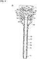
- FIG. 3 is an enlarged view of Dashed Line Portion 3 in FIG. 2 .
- FIG. 4 is a plan view of the introducer sheath according to Embodiment 1.
- FIG. 5 is an enlarged view corresponding to FIG. 3 and illustrating an introducer set according to Modification Example 1 of Embodiment 1.
- FIG. 6 is a plan view of an introducer sheath according to Modification Example 1 of Embodiment 1.
- FIG. 7 is a plan view of an introducer sheath according to Modification Example 2 of Embodiment 1.
- FIG. 8 is a plan view of an introducer sheath according to Embodiment 2.
- FIG. 9 is a plan view of an introducer sheath according to a modification example of Embodiment 2.
- FIGS. 1 to 4 are diagrams illustrating each portion of the introducer set 10 .
- the introducer set 10 that is in a state where a dilator 30 is inserted in a catheter main body 110 of an introducer sheath 20 is referred to as an introducer assembly in this specification.
- the side on which a hub 120 of the introducer sheath 20 and a dilator hub 32 of the dilator 30 are disposed (upper side in FIG. 1 ) is referred to as the “proximal side” (proximal end).
- proximal side proximal end
- distal side distal end
- distal portion means a certain range including the distal end (the most distal end) and the periphery of the distal end (the most distal end) and “proximal portion” means a certain range including the proximal end (the most proximal end) and the periphery of the proximal end (the most proximal end).
- the introducer set 10 includes the introducer sheath 20 (corresponding to a medical elongated body) and the dilator 30 (corresponding to a medical instrument).
- the introducer sheath 20 and the dilator 30 will be described in detail below.
- the introducer sheath 20 is placed into or positioned in a body lumen such as a blood vessel and forms an access path connecting the inside of a living body and the outside of the living body.
- the introducer sheath 20 is used for inserting medical instruments such as a catheter and a guide wire through a lumen 111 of the introducer sheath 20 and inserting or introducing the medical instruments into a body lumen in a state where the introducer sheath 20 is placed or positioned in the body lumen.
- PTCA/PCI percutaneous coronary intervention
- Approach methods for the percutaneous coronary intervention include trans femoral intervention (TFI) for introducing the introducer sheath 20 from a foot blood vessel and trans radial intervention (TRI) for introducing the introducer sheath 20 from an arm blood vessel.
- the introducer sheath 20 includes the catheter main body 110 (corresponding to a tubular body) insertable into a body lumen, the hub 120 having an internal space 121 communicating with the lumen 111 of the catheter main body 110 and disposed at a proximal portion 114 of the catheter main body 110 , a hemostatic valve 130 (corresponding to a valve body) disposed in the internal space 121 and having an insertion portion 131 , a cap 140 (corresponding to a cap member) fixing the hemostatic valve 130 , and a strain relief 150 surrounding a predetermined range on the proximal side of the catheter main body 110 .
- the catheter main body 110 corresponding to a tubular body
- the hub 120 having an internal space 121 communicating with the lumen 111 of the catheter main body 110 and disposed at a proximal portion 114 of the catheter main body 110
- a hemostatic valve 130 disposed in the internal space 121 and having an insertion portion 131
- a cap 140 corresponding to a cap member fixing the hemostatic valve 130
- a substantially cylindrical tubular member having the lumen 111 constitutes the catheter main body 110 .
- the catheter main body 110 has a tapered distal portion 112 , a main body portion 113 located on the proximal side of the distal portion 112 , and the proximal portion 114 located on the proximal side of the main body portion 113 and connected to the hub 120 .
- the constituent material from which the catheter main body 110 may be fabricated is not particularly limited.
- the constituent material include a polyolefin (such as polyethylene, polypropylene, polybutene, an ethylene-propylene copolymer, an ethylene-vinyl acetate copolymer, an ionomer, and a mixture of two or more of the materials), a polyolefin elastomer, a cross-linked polyolefin, polyvinyl chloride, a polyamide, a polyamide elastomer, a polyester, a polyester elastomer, polyurethane, a polyurethane elastomer, fluororesin, polycarbonate, polystyrene, polyacetal, polyimide, polyetherimide, an ethylene-tetrafluoroethylene copolymer (ETFE), a tetrafluoroethylene-hexafluoropropylene copolymer (FEP), polyether ether ketone (
- a hydrophilic lubricating layer 116 which provides surface lubricity when wet, is disposed on an outer surface 115 of the catheter main body 110 .
- the material that constitutes the hydrophilic lubricating layer 116 exhibits hydrophilicity and swelling when in contact with an aqueous solvent.
- the material that constitutes the hydrophilic lubricating layer 116 is not particularly limited insofar as the material exhibits hydrophilicity and swelling when in contact with an aqueous solvent. Known materials can be used as the material.
- the hub 120 has the internal space 121 and a side port 122 communicating with the internal space 121 .
- the internal space 121 communicates with the lumen 111 of the catheter main body 110 .
- the hemostatic valve 130 is disposed in the internal space 121 .
- a flexible tube 71 (see FIG. 1 ) is connected in a liquid-tight manner to the side port 122 .
- a three-way stopcock 72 is mounted at the other end of the tube 71 .
- the side port 122 allows a liquid such as a physiological salt solution (saline solution) to be injected from the port of the three-way stopcock 72 into the lumen 111 of the catheter main body 110 via the tube 71 .
- the tube 71 may be, for example, a known tube made of polyvinyl chloride.
- the dilator hub 32 (described later) is fitted from the outside to the hub 120 (see FIG. 3 ).
- the hub 120 has an engagement groove 171 , which engages with an engagement claw 172 of the dilator hub 32 .
- the engagement groove 171 is shaped so as to be recessed from the outer surface 128 of the hub 120 toward the center side of the catheter main body 110 .
- the engagement groove 171 is annularly formed along the circumferential direction of the catheter main body 110 .
- the constituent material from which the hub 120 may be fabricated is not particularly limited.
- a rigid material such as a rigid resin is suitable as the constituent material for the hub 120 .
- Specific examples of the rigid resin include a polyolefin such as polyethylene and polypropylene, a polyamide, polycarbonate, and polystyrene.
- the hemostatic valve 130 is disposed in the internal space 121 of the hub 120 .
- the hemostatic valve 130 is attached to a proximal portion 126 of the hub 120 .
- the hemostatic valve 130 has a substantially elliptical membrane shape (disk shape). The hemostatic valve 130 prevents the blood that has flowed into the catheter main body 110 from leaking to the outside.
- the hemostatic valve 130 includes the insertion portion 131 .
- the insertion portion 131 is configured to allow insertion of the dilator 30 and a medical instrument such as a catheter and a guide wire used for the target procedure.
- the hemostatic valve 130 has a proximal surface 132 facing toward the proximal side of the catheter main body 110 and a distal surface 133 facing toward the distal side of the catheter main body 110 .
- the constituent material from which the hemostatic valve 130 may be fabricated is not particularly limited.
- Examples of the constituent material include silicone rubber, latex rubber, butyl rubber, and isoprene rubber as elastic members.
- the proximal portion 114 of the catheter main body 110 is fixed to an interlock portion 127 of the hub 120 .
- the proximal portion 114 of the catheter main body 110 and the interlock portion 127 of the hub 120 can be fixed by an adhesive or the like.
- the cap 140 is attached to the hemostatic valve 130 .
- the hemostatic valve 130 is fixed in the internal space 121 by being pinched between the hub 120 and the cap 140 .
- the cap 140 fixes the hemostatic valve 130 in the internal space 121 by being attached to the hemostatic valve 130 disposed in the concave portion of the hub 120 as illustrated in FIG. 2 .
- the cap 140 has a proximal opening portion 141 , which is capable of communicating with the internal space 121 via the insertion portion 131 .
- the strain relief 150 is externally fitted to the catheter main body 110 and the hub 120 .
- the strain relief 150 covers a distal portion 125 of the hub 120 and surrounds a predetermined range on the proximal side of the catheter main body 110 .
- the constituent material from which the strain relief 150 may be fabricated is not particularly limited.
- Examples of the constituent material include natural rubber and silicone resins.
- the dilator 30 includes a dilator main body 31 and the dilator hub 32 , which is configured to be connectable to the hub 120 .
- the dilator main body 31 is insertable into the lumen 111 of the catheter main body 110 .
- a substantially cylindrical tubular member having a lumen 31 a constitutes the dilator main body 31 .
- the lumen 31 a is configured to allow insertion of a medical instrument such as a guide wire.
- a distal portion 31 b of the dilator main body 31 is formed in a tapered shape and tapers in a narrowing manner toward the distal side.
- the dilator hub 32 is connected to the hub 120 of the catheter main body 110 in a state where the dilator main body 31 is inserted or positioned in the lumen 111 of the catheter main body 110 .
- the dilator hub 32 is fitted to the hub 120 of the catheter main body 110 from the outside of the catheter main body 110 .
- the dilator hub 32 has the engagement claw 172 , which engages the engagement groove 171 of the hub 120 of the catheter main body 110 .
- the distal portion 31 b of the dilator main body 31 protrudes from the distal portion 112 of the catheter main body 110 in a state where the hub 120 of the introducer sheath 20 and the dilator hub 32 are connected to each other.
- the introducer sheath 20 is inserted into a body lumen in the state of the introducer assembly in which the dilator main body 31 is positioned in the lumen 111 of the catheter main body 110 and the distal portion 31 b of the dilator main body 31 protrudes from (i.e., distally beyond) the distal portion 112 of the catheter main body 110 .
- the introducer sheath 20 is capable of widening a skin perforation with the distal portion 31 b of the dilator main body 31 and preventing folding of the catheter main body 110 during introducer assembly insertion into a body lumen.
- the material from which the dilator main body 31 may be fabricated is not particularly limited. Materials similar to conventionally used materials can be used for the dilator main body 31 . Specific examples of the material include polyolefins such as polypropylene (PP) and polyethylene (PE), polyesters such as nylon and polyethylene terephthalate (PET), and fluorine-based polymers such as polyvinylidene fluoride (PVDF) and a tetrafluoroethylene-hexafluoropropylene copolymer (FEP).
- PP polypropylene
- PE polyethylene
- PET polyethylene terephthalate
- FEP tetrafluoroethylene-hexafluoropropylene copolymer
- the constituent material from which the dilator hub 32 may be fabricated is also not particularly limited.
- a rigid material such as a rigid resin is suitable for the dilator hub 32 .
- Specific examples of the rigid resin include a polyolefin such as polyethylene and polypropylene, a polyamide, polycarbonate, and polystyrene.
- the cap 140 has a marker portion 160 , which guides a medical instrument inserted into the catheter main body 110 to the valve body.
- the marker portion 160 has a color that is color-perceptually distinguishable from the periphery of the marker portion 160 . That is, there is a visually-observable color difference between the color of the marker portion 160 and the color of the portion of the cap 140 surrounding the marker portion 160 .
- the color of the marker portion 160 is not particularly limited in terms of color type.
- the color of the marker portion 160 may be different from the color of the periphery the marker portion 160 . It is preferable for marker portion visibility improvement that the color of the marker portion 160 is different from the color of the periphery of the marker portion 160 and the color of the hemostatic valve 130 .
- the marker portion 160 can be white in a case where the hemostatic valve 130 is colorless and transparent and the cap 140 is green. It is preferable that the hue difference between the colors of the marker portion 160 and the cap 140 is large (i.e., there is preferably a significant hue difference between the color of the marker portion 160 and color of the cap 140 ).
- the colors of the marker portion 160 and the cap 140 may be complementary to each other.
- the center side of the hemostatic valve 130 refers to the direction from the catheter main body 110 toward the insertion hole 136 .
- the marker portion 160 may have a point-symmetrical shape with reference to the center portion of the hemostatic valve 130 in the radial direction of the catheter main body 110 .
- the center portion of the hemostatic valve 130 in the radial direction of the catheter main body 110 is the insertion hole 136 .
- the marker portion 160 may have a ring shape or annular shape in plan view and may be spaced radially outwardly from the center of the valve body 130 .
- a center side end portion 161 of the marker portion 160 forms the peripheral edge portion (inner peripheral edge) of the marker portion 160
- the center side end portion 161 of the marker portion 160 i.e., the inner peripheral edge of the marker portion 160
- the center side end portion 161 of the marker portion 160 is the place at which the inner periphery of the marker portion 160 intersects an axially outwardly facing surface of the hemostatic valve 130 .
- the marker portion 160 is disposed on the cap 140 so as to surround a surface 132 a of the hemostatic valve 130 that is visually recognizable via the proximal opening portion 141 .
- the surface 132 a of the hemostatic valve 130 visually recognizable via the proximal opening portion 141 refers to the region that constitutes the proximal surface 132 of the hemostatic valve 130 and is visually recognizable from the proximal opening portion 141 in plan view of the introducer sheath 20 .
- the cap 140 has a guiding wall surface portion 142 , which forms the proximal opening portion 141 .
- the guiding wall surface portion 142 has a slope portion 143 , which is inclined from the proximal side toward the distal side (inclined inwardly in a narrowing manner in the distal direction).
- the marker portion 160 is disposed on the slope portion 143 .
- the insertion portion 131 includes a proximal side slit 134 disposed in the proximal surface 132 and open to the proximal side and a distal side slit 135 disposed in the distal surface 133 and open to the distal side.
- the insertion portion 131 includes the insertion hole 136 at the place where the proximal side slit 134 and the distal side slit 135 intersect each other.
- a medical instrument is insertable into the lumen 111 of the catheter main body 110 via the insertion hole 136 .
- a curved surface directed from the proximal side toward the distal side constitutes the entire surface of the guiding wall surface portion 142 .
- the center side end portion 161 (peripheral edge portion) of the marker portion 160 is disposed closer to the center side of the hemostatic valve 130 than end portions 134 a and 135 a of the slits 134 and 135 constituting the insertion portion 131 .
- the end portions 134 a and 135 a of the slits 134 and 135 are positioned further radially outwardly than the center side end portion 161 (peripheral edge portion) of the marker portion 160 as shown in FIG. 4 .
- the center side end portion 161 (peripheral edge portion) of the marker portion 160 is in contact with the hemostatic valve 130 .
- the marker portion 160 disposed on the cap 140 is in contact with the hemostatic valve 130 by the cap 140 pressing the elastic hemostatic valve 130 .
- the marker portion 160 disposed on the cap 140 is disposed so as to cover a projection portion 144 (described later), and thus the marker portion 160 disposed on the cap 140 comes into contact with the hemostatic valve 130 when the cap 140 is attached to the hemostatic valve 130 .
- the cap 140 has the projection portion 144 , which protrudes toward the hemostatic valve 130 and presses the center of the hemostatic valve 130 so as to be concave to the distal side.
- the proximal surface 132 of the hemostatic valve 130 includes a curved surface 132 b , which is concavely curved by the projection portion 144 .
- the curved surface of the guiding wall surface portion 142 is smoothly continuous with the curved surface 132 b.
- the distal portion 31 b of the dilator 30 is provided with a distal end marker portion 33 , which has a color that is color-perceptually distinguishable (i.e., a color that is visually distinguishable) from the surrounding.
- the distal end marker portion 33 can be red in a case where, for example, the dilator main body 31 is blue.
- the cap 140 has the marker portion 160 , which guides a medical instrument inserted into the catheter main body 110 to the hemostatic valve 130 .
- the marker portion 160 has a color distinguishable (visually distinguishable) from the periphery or surrounding portion of the marker portion 160 .
- the operator can easily guide the distal portion of the medical instrument to the vicinity of the center of the hemostatic valve 130 by aiming at the position indicated by the marker portion 160 . Accordingly, it is possible to provide an introducer sheath having a simple structure that allows quick insertion of a medical instrument into a catheter main body lumen via a hemostatic valve.
- the operator can easily guide the distal portion of the medical instrument to the vicinity of the center of the hemostatic valve 130 .
- contact between the most distal end of the medical instrument and a place other than the hemostatic valve 130 can be suppressed or reduced when the operator inserts the medical instrument into the lumen 111 of the catheter main body 110 via the hemostatic valve 130 . Accordingly, it is possible to inhibit damage to the distal portion of the medical instrument attributable to contact with a place other than the hemostatic valve 130 .
- the operator can easily inhibit damage to the dilator 30 attributable to contact between the distal portion 31 b of the dilator 30 and a place other than the hemostatic valve 130 by aligning the distal portion 31 b of the dilator 30 in the marker portion 160 .
- the marker portion 160 is disposed on the cap 140 so as to surround the surface 132 a of the hemostatic valve 130 that is visually recognizable via the proximal opening portion 141 .
- the operator can more easily grasp the position of the hemostatic valve 130 by visually recognizing the marker portion 160 on the hand-side of the introducer sheath 20 . Accordingly, the operator can more easily guide the distal portion of the medical instrument to the vicinity of the center of the hemostatic valve 130 .
- the marker portion 160 is disposed on the slope portion 143 of the guiding wall surface portion 142 .
- the distal portion of the medical instrument comes into contact with the slope portion 143 even in the event of deviation of the distal portion of the medical instrument from the vicinity of the center of the hemostatic valve 130 to the marker portion 160 side.
- the distal portion of the medical instrument that is in contact with the slope portion 143 is guided to the hemostatic valve 130 along the slope portion 143 , and thus damage to the medical instrument can be inhibited. Accordingly, the necessity for the operator to pay attention such that the distal portion of the medical instrument does not come into contact with a place other than the hemostatic valve 130 is reduced.
- the slope portion 143 inclined toward the hemostatic valve 130 is easily visible in plan view. Accordingly, the operator can easily grasp the position of the marker portion 160 and the medical instrument and the marker portion 160 are aligned with ease.
- the center side end portion 161 of the marker portion 160 is disposed closer to the center side of the hemostatic valve 130 than the end portions 134 a and 135 a of the slits 134 and 135 constituting the insertion portion 131 . That is, that the center side end portion 161 of the marker portion 160 is disposed inwardly (radially inwardly) of the end portions 134 a , 135 a of the slits 134 , 135 .
- the operator can easily grasp the positions of the slits 134 and 135 by using the marker portion 160 as a mark. Accordingly, it is possible to easily inhibit damage to the hemostatic valve 130 attributable to contact between the distal portion 31 b of the dilator 30 and a place other than the insertion portion 131 of the hemostatic valve 130 .
- a curved surface directed from the proximal side toward the distal side constitutes the entire surface of the guiding wall surface portion 142 . Accordingly, damage to the medical instrument can be inhibited even in the event of contact between the medical instrument and the guiding wall surface portion 142 .
- the center side end portion 161 of the marker portion 160 is in contact with the hemostatic valve 130 .
- the operator can more clearly distinguish the boundary between the hemostatic valve 130 and the part other than the hemostatic valve 130 by visually recognizing the marker portion 160 .
- the operator can more easily guide the distal portion of the medical instrument to the vicinity of the center of the hemostatic valve 130 by aiming at the position indicated by the marker portion 160 .
- the medical elongated body is the introducer sheath 20 and the distal portion 31 b of the dilator 30 is provided with the distal end marker portion 33 , which has a color distinguishable from the surrounding.
- the operator can more easily guide the distal portion 31 b of the dilator 30 to the vicinity of the center of the hemostatic valve 130 by aligning the marker portion 160 of the introducer sheath 20 and the distal end marker portion 33 of the dilator 30 in forming the introducer assembly by inserting the dilator 30 into the lumen 111 of the catheter main body 110 .
- the cap 140 has the projection portion 144 , which protrudes toward the hemostatic valve 130 and presses the center of the hemostatic valve 130 so as to be concave to the distal side.
- the proximal surface 132 of the hemostatic valve 130 includes the curved surface 132 b , which is concavely curved by the projection portion 144 .
- the curved surface of the guiding wall surface portion 142 is smoothly continuous with the curved surface 132 b .
- the medical instrument is guided by the curved surface 132 b smoothly continuous from the guiding wall surface portion 142 and guided to the middle portion of the hemostatic valve 130 , which has a small resistance force at a time of insertion, even in the case of contact with a place other than the insertion portion 131 of the hemostatic valve 130 or the guiding wall surface portion 142 . Accordingly, injuries to the medical instrument and the hemostatic valve 130 can be inhibited.
- the dilator 30 is fitted to the outside of the introducer sheath 20 .
- the dilator 30 may be fitted to the inside of the introducer sheath 20 .
- FIG. 5 which corresponds to FIG. 3 , is an enlarged view illustrating an introducer set according to the present modification example.
- FIG. 6 is a plan view of an introducer sheath according to the present modification example.
- the cap 140 has an engagement claw 281 , which engages with an engagement claw 282 of the dilator hub 32 .
- the engagement claw 281 protrudes toward the center side of the catheter main body 110 in the proximal opening portion 141 of the cap 140 .
- the dilator hub 32 has the engagement claw 282 , which engages with the engagement claw 281 of the cap 140 .
- the engagement claw 282 protrudes from a surface of the dilator hub 32 that faces the distal side and extends along the axial direction.
- the guiding wall surface portion 142 has a slope portion 243 , which forms the proximal opening portion 141 .
- the slope portion 243 has a first slope portion 243 a and a second slope portion 243 b , which is formed closer to the distal side than the first slope portion 243 a .
- the first slope portion 243 a functions as the engagement claw 281 of the introducer sheath 20 .
- the second slope portion 243 b protrudes to the center side of the catheter main body 110 beyond the first slope portion 243 a.
- a marker portion 260 has a first marker portion 261 disposed on the first slope portion 243 a and a second marker portion 262 disposed on the second slope portion 243 b.
- the colors of the first marker portion 261 and the second marker portion 262 are color-perceptually distinguishable from each other, the first marker portion 261 and the second marker portion 262 may have the same color.
- the first marker portion 261 can be black and the second marker portion 262 can be white.
- the first marker portion 261 and the second marker portion 262 are disposed so as to surround the surface 132 a of the hemostatic valve 130 that is visually recognizable via the proximal opening portion 141 .
- the first marker portion 261 and the second marker portion 262 have a ring shape or annular shape in plan view.
- a center side end portion 262 a of the second marker portion 262 forms the peripheral edge portion of the marker portion 260 that is on the distal side along the circumferential direction of the catheter main body 110 .
- the center side end portion 262 a (peripheral edge portion) of the second marker portion 262 is disposed closer to the center side of the hemostatic valve 130 than the end portions 134 a and 135 a of the slits 134 and 135 constituting the insertion portion 131 .
- the end portions 134 a and 135 a of the slits 134 and 135 are positioned further radially outwardly than the center side end portion 262 a of the second marker portion 262 .
- the center side end portion 262 a (peripheral edge portion) of the second marker portion 262 is in contact with the hemostatic valve 130 .
- the present modification example is similar in action and effect to the introducer set 10 according to the embodiment described above.
- the marker portion may be comprised of a plurality of colors.
- FIG. 7 is a plan view of an introducer sheath according to such a modification example.
- a marker portion 360 of the introducer sheath according to the present modification example includes a first region 361 and a second region 362 , which is different in color from the first region 361 .
- several of the first regions 361 and several of the second regions 362 are provided, with the first regions 361 and the second regions 362 circumferentially alternating with one another as depicted by way of example in FIG. 7 .
- the overall configuration of the marker portion 360 is the same as the overall configuration of the marker portion 160 according to the above-described embodiment, except that the marker portion 360 depicted in the FIG. 7 embodiment is defined by the circumferentially alternating first and second regions 361 , 362 .
- Each of the second regions 362 is disposed at a predetermined position between two of the first regions 361 , and the first regions 361 and the second regions 362 are located at a radially outward portion of the hemostatic valve 130 .
- a width L of the second region 362 decreases from the outer periphery of the cap 140 toward the hemostatic valve 130 .
- “width” means the length of the second region 362 along the circumferential direction of the catheter main body 110 .
- the visibility of the marker portion 360 is improved. Accordingly, the distal portion of a medical instrument can be more easily guided to the vicinity of the center of the hemostatic valve 130 by a simple structure, that is, by the marker portion 360 being provided.
- the colors that constitute the marker portion 360 are not limited to the two colors described above. Alternatively, three or more colors may constitute the marker portion 360 .
- the first marker portion 261 and/or the second marker portion 262 of Modification Example 1 described above may be similar in configuration to the marker portion 360 according to the present modification example.
- the marker portion 160 is provided on the cap 140 .
- a marker portion may be provided on the hemostatic valve 130 .
- An introducer set according to the present embodiment is similar in configuration to the introducer sets according to the above-described embodiment and modification examples except for the configuration of the marker portion. Accordingly, only the marker portion will be described below.
- FIG. 8 is a plan view of an introducer sheath according to the present embodiment.
- the hemostatic valve 130 has a marker portion 460 , which guides a medical instrument inserted into catheter main body 110 to the insertion portion 131 .
- the marker portion 460 has a color that is color-perceptually distinguishable from the periphery of the marker portion 460 . That is, the color of the marker portion 460 is visually distinguishable from the color of the periphery of the marker portion 460 .
- the marker portion 460 is not particularly limited in terms of color type.
- the marker portion 160 can be white in a case where the hemostatic valve 130 is colorless and transparent and the cap 140 is green.
- the marker portion 460 may be a circular or disk-shaped marker portion.
- the marker portion 460 is provided so as to surround the insertion hole 136 of the hemostatic valve 130 on the curved surface 132 b (see FIG. 2 ) of the hemostatic valve 130 .
- the introducer sheath may also include a slit distinguishing portion 480 that makes the proximal side slit 134 and the distal side slit 135 distinguishable from each other.
- the slit distinguishing portion 480 indicates the position of the proximal side slit 134 .
- the slit distinguishing portion 480 is positioned on the proximal facing surface of the valve body 130 and may be configured as an arrow shape indicating the position of the proximal side slit 134 .
- the distal surface of the valve body 13 may be devoid of any slit distinguishing portions.
- the slit distinguishing portion 480 is disposed in the marker portion 460 .
- the slit distinguishing portion 480 may be of a color that is color-perceptually distinguishable from the marker portion 460 . That is, the color of the slit distinguishing portion 480 is visually distinguishable from the color of the marker portion 460 .
- the introducer sheath according to the present embodiment has the following actions and effects in addition to the actions and effects of the introducer sheath 20 according to the above-described embodiment.
- an operator can easily grasp the position of the insertion portion 131 of the hemostatic valve 130 by visually recognizing the position of the marker portion 460 in inserting a medical instrument into the lumen 111 of the catheter main body 110 via the hemostatic valve 130 . Accordingly, it is possible to easily inhibit damage to the hemostatic valve 130 attributable to contact between the distal portion of the medical instrument and a place other than the insertion portion 131 of the hemostatic valve 130 when the operator inserts the medical instrument into the lumen 111 of the catheter main body 110 via the hemostatic valve 130 .
- the marker portion 460 is provided so as to surround the insertion hole 136 . Accordingly, it is possible to prevent contact between the distal portion of the medical instrument and a place other than the insertion hole 136 when the operator inserts the medical instrument into the lumen 111 of the catheter main body 110 via the hemostatic valve 130 . Accordingly, damage to the hemostatic valve 130 can be easily and more reliably inhibited.
- the distal side slit 135 is provided in the distal surface 133 of the hemostatic valve 130 and is open to the distal side. Accordingly, the risk of the hemostatic valve 130 being injured by the distal portion of the medical instrument is high in a case where the medical instrument is moved in toward the distal side slit 135 instead of the insertion hole 136 .
- the proximal side slit 134 is provided in the proximal surface 132 of the hemostatic valve 130 and is open to the proximal side.
- the operator can insert the medical instrument through the insertion hole 136 while inhibiting or avoiding damage to the hemostatic valve 130 , by moving the distal portion of the medical instrument along the proximal side slit 134 , even with the medical instrument moved in toward the proximal side slit 134 instead of the insertion hole 136 .
- the introducer sheath With the introducer sheath according to the present embodiment, it is possible to distinguish the proximal side slit 134 and the distal side slit 135 from each other by visually recognizing the slit distinguishing portion 480 . Accordingly, it is possible to reduce the risk that the operator erroneously moves the medical instrument into the distal side slit 135 when the operator inserts the medical instrument into the lumen of the catheter main body via the hemostatic valve. As a result, it is possible to provide an introducer sheath having a simple structure that allows more reliable prevention of damage to the hemostatic valve 130 during insertion of the medical instrument into the lumen 111 of the catheter main body 110 via the hemostatic valve 130 .
- the marker portion may have a plurality of colors.
- FIG. 9 is a plan view of an introducer sheath according to the present modification example.
- a marker portion 560 according to the present modification example includes a first region 561 and a second region 562 , which is different in color from the first region 561 .
- the configuration of the first region 561 is the same as the configuration of the marker portion 460 according to Embodiment 2 described above.
- the second region 562 is disposed closer to the center side of the introducer sheath 20 (center side of the hemostatic valve 130 ) than the first region 561 .
- the second region 562 has a circular shape about the insertion hole 136 .
- the second region 562 can be, for example, red.
- FIG. 9 exemplifies a case where the marker portion has two colors
- the colors that constitute the marker portion are not limited to the two colors described above and three or more colors may constitute the marker portion. It is possible to improve the visibility of the marker portion by changing the shape of the marker portion or the colors constituting the marker portion and the combination of the colors.
- the marker portion is provided on either the hemostatic valve 130 or the cap 140 .
- the marker portion may be provided on both the hemostatic valve 130 and the cap 140 .
- the form of the slit distinguishing portion 480 is a form that has an arrow shape indicating the position of the proximal side slit 134 .
- the slit distinguishing portion 480 may have any form as long as it can make the proximal side slit 134 and the distal side slit 135 distinguishable from each other.
- the form may be a triangular or rhombic shape that indicates the position of the proximal side slit 134 .
- a belt-shaped site having a color that is color-perceptually distinguishable from the surrounding may be formed along the proximal side slit 134 and the site may be used as the slit distinguishing portion 480 .
- the slit distinguishing portion 480 may be provided on the cap 140 .
- the hemostatic valve 130 and/or the cap 140 of the introducer sheaths according to Embodiment 1 and the modification examples of Embodiment 1 may also be provided with the slit distinguishing portion.
- the dilator is connected to the hub of the catheter main body in Embodiment 1, Modification Example 2 of Embodiment 1, Embodiment 2, and the modification example of Embodiment 2.
- the dilator may be configured to be connected to the cap.
- Methods for connecting the dilator and the cap to each other are not particularly limited.
- the dilator and the cap can be connected to each other by, for example, a method of forming an engagement claw on the cap as in Modification Example 1 of Embodiment 1.
Landscapes
- Health & Medical Sciences (AREA)
- Life Sciences & Earth Sciences (AREA)
- Heart & Thoracic Surgery (AREA)
- Biomedical Technology (AREA)
- Engineering & Computer Science (AREA)
- Anesthesiology (AREA)
- Pulmonology (AREA)
- Hematology (AREA)
- Animal Behavior & Ethology (AREA)
- General Health & Medical Sciences (AREA)
- Public Health (AREA)
- Veterinary Medicine (AREA)
- Biophysics (AREA)
- Media Introduction/Drainage Providing Device (AREA)
- Infusion, Injection, And Reservoir Apparatuses (AREA)
Abstract
Description
Claims (22)
Applications Claiming Priority (3)
| Application Number | Priority Date | Filing Date | Title |
|---|---|---|---|
| JP2017023529 | 2017-02-10 | ||
| JP2017-023529 | 2017-02-10 | ||
| PCT/JP2018/004439 WO2018147380A1 (en) | 2017-02-10 | 2018-02-08 | Medical long body and medical long body set |
Related Parent Applications (1)
| Application Number | Title | Priority Date | Filing Date |
|---|---|---|---|
| PCT/JP2018/004439 Continuation WO2018147380A1 (en) | 2017-02-10 | 2018-02-08 | Medical long body and medical long body set |
Publications (2)
| Publication Number | Publication Date |
|---|---|
| US20190344051A1 US20190344051A1 (en) | 2019-11-14 |
| US11291805B2 true US11291805B2 (en) | 2022-04-05 |
Family
ID=63107591
Family Applications (1)
| Application Number | Title | Priority Date | Filing Date |
|---|---|---|---|
| US16/519,723 Active 2038-05-23 US11291805B2 (en) | 2017-02-10 | 2019-07-23 | Medical elongated body and medical elongated body set |
Country Status (4)
| Country | Link |
|---|---|
| US (1) | US11291805B2 (en) |
| JP (1) | JP7084324B2 (en) |
| CN (1) | CN109952125B (en) |
| WO (1) | WO2018147380A1 (en) |
Cited By (4)
| Publication number | Priority date | Publication date | Assignee | Title |
|---|---|---|---|---|
| US12403296B2 (en) | 2018-05-30 | 2025-09-02 | Kardion Gmbh | Apparatus for anchoring a ventricular assist system in a blood vessel, operating method, production method for producing an apparatus and ventricular assist system |
| US12415055B2 (en) | 2017-09-29 | 2025-09-16 | Terumo Kabushiki Kaisha | Catheter assembly and medical valve |
| US12478775B2 (en) | 2018-07-09 | 2025-11-25 | Kardion Gmbh | Cardiac assist system, and method for monitoring the integrity of a retaining structure of a cardiac assist system |
| US12508402B2 (en) | 2019-03-28 | 2025-12-30 | Terumo Kabushiki Kaisha | Catheter assembly |
Families Citing this family (4)
| Publication number | Priority date | Publication date | Assignee | Title |
|---|---|---|---|---|
| DE112020005548T5 (en) * | 2019-11-14 | 2022-08-25 | Abiomed, Inc. | HEMOSTASIS VALVE FOR SHEATH ASSEMBLY |
| WO2021144915A1 (en) * | 2020-01-16 | 2021-07-22 | 朝日インテック株式会社 | Medical tool gripper |
| US20220054817A1 (en) * | 2020-08-18 | 2022-02-24 | Baylis Medical Company Inc. | Cover for use with sheath hub and dilator hub |
| US20240058582A1 (en) * | 2022-08-19 | 2024-02-22 | Cook Medical Technologies Llc | Medical introducer and sheath |
Citations (6)
| Publication number | Priority date | Publication date | Assignee | Title |
|---|---|---|---|---|
| US20030233083A1 (en) | 2002-06-12 | 2003-12-18 | Vincent Houwaert | Port, a container and a method for accessing a port |
| CN101020093A (en) | 2006-02-14 | 2007-08-22 | 朝日印帝克股份有限公司 | A medical apparatus, tubular insertion device and a tubular insertion device having the same medical apparatus |
| US20130158519A1 (en) | 2002-10-08 | 2013-06-20 | Boston Scientific Scimed, Inc. | Catheter with formed guide wire ramp |
| JP2013208428A (en) | 2012-03-23 | 2013-10-10 | Terumo Medical Corp | Dilator centering device and assembly |
| CN103619399A (en) | 2011-07-04 | 2014-03-05 | 泰尔茂株式会社 | Introducer sheath |
| US20140276037A1 (en) | 2013-03-15 | 2014-09-18 | Devicor Medical Products, Inc. | Biopsy site marker applier |
-
2018
- 2018-02-08 CN CN201880004287.1A patent/CN109952125B/en active Active
- 2018-02-08 JP JP2018567496A patent/JP7084324B2/en not_active Expired - Fee Related
- 2018-02-08 WO PCT/JP2018/004439 patent/WO2018147380A1/en not_active Ceased
-
2019
- 2019-07-23 US US16/519,723 patent/US11291805B2/en active Active
Patent Citations (12)
| Publication number | Priority date | Publication date | Assignee | Title |
|---|---|---|---|---|
| US20030233083A1 (en) | 2002-06-12 | 2003-12-18 | Vincent Houwaert | Port, a container and a method for accessing a port |
| CN1658814A (en) | 2002-06-12 | 2005-08-24 | 巴克斯特国际公司 | Port, container and method of using a port |
| JP2009189861A (en) | 2002-06-12 | 2009-08-27 | Baxter Internatl Inc | Port, container and how to access the port |
| US20130158519A1 (en) | 2002-10-08 | 2013-06-20 | Boston Scientific Scimed, Inc. | Catheter with formed guide wire ramp |
| CN101020093A (en) | 2006-02-14 | 2007-08-22 | 朝日印帝克股份有限公司 | A medical apparatus, tubular insertion device and a tubular insertion device having the same medical apparatus |
| US20080039823A1 (en) | 2006-02-14 | 2008-02-14 | Asahi Intecc Co. Ltd. | Medical Equipment, Tubular Insertion Device and Tubular Insertion Device Having the Same Medical Equipment |
| CN103619399A (en) | 2011-07-04 | 2014-03-05 | 泰尔茂株式会社 | Introducer sheath |
| US20140114286A1 (en) * | 2011-07-04 | 2014-04-24 | Terumo Kabushiki Kaisha | Introducer sheath |
| JP2016215026A (en) | 2011-07-04 | 2016-12-22 | テルモ株式会社 | Sheath for introducer |
| JP2013208428A (en) | 2012-03-23 | 2013-10-10 | Terumo Medical Corp | Dilator centering device and assembly |
| US20140276037A1 (en) | 2013-03-15 | 2014-09-18 | Devicor Medical Products, Inc. | Biopsy site marker applier |
| CN105073022A (en) | 2013-03-15 | 2015-11-18 | 德维克医疗产品公司 | Biopsy site marker releaser |
Non-Patent Citations (4)
| Title |
|---|
| An English Translation of the International Search Report (Form PCT/ISA/210) and the Written Opinion of the International Searching Authority (Form PCT/ISA/237) dated May 1, 2018, by the Japanese Patent Office in corresponding International Application No. PCT/JP2018/004439. (9 pages). |
| International Search Report (PCT/ISA/210) dated May 1, 2018, by the Japanese Patent Office as the International Searching Authority for International Application No. PCT/JP2018/004439. |
| Office Action (The First Office Action) dated Apr. 26, 2021, by the State Intellectual Property Office of People's Republic of China in corresponding Chinese Patent Application No. 201880004287.1 and an English Translation of the Office Action. (17 pages). |
| Written Opinion (PCT/ISA/237) dated May 1, 2018, by the Japanese Patent Office as the International Searching Authority for International Application No. PCT/JP2018/004439. |
Cited By (4)
| Publication number | Priority date | Publication date | Assignee | Title |
|---|---|---|---|---|
| US12415055B2 (en) | 2017-09-29 | 2025-09-16 | Terumo Kabushiki Kaisha | Catheter assembly and medical valve |
| US12403296B2 (en) | 2018-05-30 | 2025-09-02 | Kardion Gmbh | Apparatus for anchoring a ventricular assist system in a blood vessel, operating method, production method for producing an apparatus and ventricular assist system |
| US12478775B2 (en) | 2018-07-09 | 2025-11-25 | Kardion Gmbh | Cardiac assist system, and method for monitoring the integrity of a retaining structure of a cardiac assist system |
| US12508402B2 (en) | 2019-03-28 | 2025-12-30 | Terumo Kabushiki Kaisha | Catheter assembly |
Also Published As
| Publication number | Publication date |
|---|---|
| JPWO2018147380A1 (en) | 2019-12-12 |
| JP7084324B2 (en) | 2022-06-14 |
| CN109952125A (en) | 2019-06-28 |
| CN109952125B (en) | 2022-04-29 |
| WO2018147380A1 (en) | 2018-08-16 |
| US20190344051A1 (en) | 2019-11-14 |
Similar Documents
| Publication | Publication Date | Title |
|---|---|---|
| US11291805B2 (en) | Medical elongated body and medical elongated body set | |
| US10835712B2 (en) | Medical tube | |
| US9149608B2 (en) | Handle having hub with rotating infusion sideport | |
| US11202897B2 (en) | Closed system catheter vent cap | |
| US7985232B2 (en) | Detachable hemostasis valve and splittable sheath assembly | |
| US6719772B2 (en) | Retaining device for axially restraining movement between tubular elements of a medical device | |
| US20140081210A1 (en) | Access device | |
| WO2018043427A1 (en) | Introducer sheath | |
| JP2005514114A (en) | Blood vessel | |
| WO2015085123A1 (en) | Cuttable catheter hub with integrated hemostasis valve | |
| US10625048B2 (en) | Introducer sheath | |
| US20230106587A1 (en) | Catheter | |
| US20140180325A1 (en) | Dilator | |
| TW202327682A (en) | Low profile access sheaths | |
| EP2165731A1 (en) | Detachable and freely rotating hemostasis valve | |
| US11786705B2 (en) | Catheter insertion devices | |
| JP2023146443A (en) | introducer | |
| US20230218877A1 (en) | Medical elongated body and medical elongated body set | |
| US20230218860A1 (en) | Medical elongated body | |
| JP2023110184A (en) | Connection member, medical assembly, and sheath introducer | |
| JP2022018318A (en) | Introducer assembly and use method of introducer assembly | |
| HK1053991A (en) | Retaining device for axially restraining movement between tubular elements of a medical device |
Legal Events
| Date | Code | Title | Description |
|---|---|---|---|
| AS | Assignment |
Owner name: TERUMO KABUSHIKI KAISHA, JAPAN Free format text: ASSIGNMENT OF ASSIGNORS INTEREST;ASSIGNORS:OUCHI, TATSUYA;OKAMURA, RYO;REEL/FRAME:049835/0302 Effective date: 20190718 |
|
| FEPP | Fee payment procedure |
Free format text: ENTITY STATUS SET TO UNDISCOUNTED (ORIGINAL EVENT CODE: BIG.); ENTITY STATUS OF PATENT OWNER: LARGE ENTITY |
|
| STPP | Information on status: patent application and granting procedure in general |
Free format text: DOCKETED NEW CASE - READY FOR EXAMINATION |
|
| STPP | Information on status: patent application and granting procedure in general |
Free format text: NON FINAL ACTION MAILED |
|
| STPP | Information on status: patent application and granting procedure in general |
Free format text: RESPONSE TO NON-FINAL OFFICE ACTION ENTERED AND FORWARDED TO EXAMINER |
|
| STPP | Information on status: patent application and granting procedure in general |
Free format text: NOTICE OF ALLOWANCE MAILED -- APPLICATION RECEIVED IN OFFICE OF PUBLICATIONS |
|
| STPP | Information on status: patent application and granting procedure in general |
Free format text: AWAITING TC RESP., ISSUE FEE NOT PAID |
|
| STPP | Information on status: patent application and granting procedure in general |
Free format text: NOTICE OF ALLOWANCE MAILED -- APPLICATION RECEIVED IN OFFICE OF PUBLICATIONS |
|
| STPP | Information on status: patent application and granting procedure in general |
Free format text: PUBLICATIONS -- ISSUE FEE PAYMENT VERIFIED |
|
| FEPP | Fee payment procedure |
Free format text: PETITION RELATED TO MAINTENANCE FEES GRANTED (ORIGINAL EVENT CODE: PTGR); ENTITY STATUS OF PATENT OWNER: LARGE ENTITY |
|
| STCF | Information on status: patent grant |
Free format text: PATENTED CASE |
|
| FEPP | Fee payment procedure |
Free format text: MAINTENANCE FEE REMINDER MAILED (ORIGINAL EVENT CODE: REM.); ENTITY STATUS OF PATENT OWNER: LARGE ENTITY |