US11288224B2 - Semiconductor system and semiconductor device - Google Patents
Semiconductor system and semiconductor device Download PDFInfo
- Publication number
- US11288224B2 US11288224B2 US16/860,915 US202016860915A US11288224B2 US 11288224 B2 US11288224 B2 US 11288224B2 US 202016860915 A US202016860915 A US 202016860915A US 11288224 B2 US11288224 B2 US 11288224B2
- Authority
- US
- United States
- Prior art keywords
- state
- controller
- connection
- port
- usb port
- Prior art date
- Legal status (The legal status is an assumption and is not a legal conclusion. Google has not performed a legal analysis and makes no representation as to the accuracy of the status listed.)
- Active
Links
Images


Classifications
-
- G—PHYSICS
- G06—COMPUTING OR CALCULATING; COUNTING
- G06F—ELECTRIC DIGITAL DATA PROCESSING
- G06F13/00—Interconnection of, or transfer of information or other signals between, memories, input/output devices or central processing units
- G06F13/10—Program control for peripheral devices
- G06F13/12—Program control for peripheral devices using hardware independent of the central processor, e.g. channel or peripheral processor
- G06F13/124—Program control for peripheral devices using hardware independent of the central processor, e.g. channel or peripheral processor where hardware is a sequential transfer control unit, e.g. microprocessor, peripheral processor or state-machine
-
- G—PHYSICS
- G06—COMPUTING OR CALCULATING; COUNTING
- G06F—ELECTRIC DIGITAL DATA PROCESSING
- G06F13/00—Interconnection of, or transfer of information or other signals between, memories, input/output devices or central processing units
- G06F13/38—Information transfer, e.g. on bus
- G06F13/40—Bus structure
- G06F13/4063—Device-to-bus coupling
- G06F13/4068—Electrical coupling
-
- G—PHYSICS
- G06—COMPUTING OR CALCULATING; COUNTING
- G06F—ELECTRIC DIGITAL DATA PROCESSING
- G06F1/00—Details not covered by groups G06F3/00 - G06F13/00 and G06F21/00
- G06F1/26—Power supply means, e.g. regulation thereof
-
- G—PHYSICS
- G06—COMPUTING OR CALCULATING; COUNTING
- G06F—ELECTRIC DIGITAL DATA PROCESSING
- G06F1/00—Details not covered by groups G06F3/00 - G06F13/00 and G06F21/00
- G06F1/26—Power supply means, e.g. regulation thereof
- G06F1/28—Supervision thereof, e.g. detecting power-supply failure by out of limits supervision
-
- G—PHYSICS
- G06—COMPUTING OR CALCULATING; COUNTING
- G06F—ELECTRIC DIGITAL DATA PROCESSING
- G06F13/00—Interconnection of, or transfer of information or other signals between, memories, input/output devices or central processing units
- G06F13/38—Information transfer, e.g. on bus
- G06F13/42—Bus transfer protocol, e.g. handshake; Synchronisation
- G06F13/4282—Bus transfer protocol, e.g. handshake; Synchronisation on a serial bus, e.g. I2C bus, SPI bus
-
- G—PHYSICS
- G06—COMPUTING OR CALCULATING; COUNTING
- G06F—ELECTRIC DIGITAL DATA PROCESSING
- G06F2213/00—Indexing scheme relating to interconnection of, or transfer of information or other signals between, memories, input/output devices or central processing units
- G06F2213/0016—Inter-integrated circuit (I2C)
-
- G—PHYSICS
- G06—COMPUTING OR CALCULATING; COUNTING
- G06F—ELECTRIC DIGITAL DATA PROCESSING
- G06F2213/00—Indexing scheme relating to interconnection of, or transfer of information or other signals between, memories, input/output devices or central processing units
- G06F2213/0042—Universal serial bus [USB]
-
- Y—GENERAL TAGGING OF NEW TECHNOLOGICAL DEVELOPMENTS; GENERAL TAGGING OF CROSS-SECTIONAL TECHNOLOGIES SPANNING OVER SEVERAL SECTIONS OF THE IPC; TECHNICAL SUBJECTS COVERED BY FORMER USPC CROSS-REFERENCE ART COLLECTIONS [XRACs] AND DIGESTS
- Y02—TECHNOLOGIES OR APPLICATIONS FOR MITIGATION OR ADAPTATION AGAINST CLIMATE CHANGE
- Y02D—CLIMATE CHANGE MITIGATION TECHNOLOGIES IN INFORMATION AND COMMUNICATION TECHNOLOGIES [ICT], I.E. INFORMATION AND COMMUNICATION TECHNOLOGIES AIMING AT THE REDUCTION OF THEIR OWN ENERGY USE
- Y02D10/00—Energy efficient computing, e.g. low power processors, power management or thermal management
Definitions
- the present invention relates to a semiconductor system and a semiconductor device, for example, the present invention relates to a semiconductor system and a semiconductor device for controlling Universal Serial Bus ports.
- USB ports conforming to USB Type-C (registered trademark) specifications (Non Patent Document 1) have been adopted.
- one Power Delivery Controller is required for each of the ports.
- Non Patent Document 2 there is a Type-C Port Controller Interface (TCPCI specification (Non Patent Document 2) as a specification of controllers for Type-C.
- the Port Manager (Type-C Port Manager; TCPM) and Port Controller (Type-C Port Controller; TCPC) are specified in the specifications for Non Patent Document 2.
- TCPC Type-C Port Controller
- system can be built with one port manager and one or more port controllers per port.
- the port manager and the port controllers are connected by I2C (Inter-Integrated Circuit) buses.
- I2C Inter-Integrated Circuit
- the port manager and the port controller communicate in the process of connecting to the USB port. Therefore, in the connection processing to the USB port, the communication time between the port manager and the port controller via the I2C bus may be a bottleneck. Therefore, as the number of ports increases, communication time may increase.
- a semiconductor system comprises a port controller configured to control a USB (Universal Serial Bus) port, and a port manager configured to control the port controller and being connected to the port controller via a I2C bus, wherein the port controller comprises a state machine configured to realize transition of a connection state in the USB port, and a controller configured to control transition in the state machine and output a connected state transition notification when the connection state transitions to a connected state that is a state in which the connection state is electrically stably connected, wherein the port manager comprises a connection detection unit configured to receive the connected state transition notification and detect a connection of the USB port, and wherein the port manager performs a process according to a connection detected by the connection detection unit.
- the port controller comprises a state machine configured to realize transition of a connection state in the USB port, and a controller configured to control transition in the state machine and output a connected state transition notification when the connection state transitions to a connected state that is a state in which the connection state is electrically stably connected
- the port manager comprises a
- a semiconductor device comprises an interface configured to be connected to a port controller which control a USB (Universal Serial Bus) port via a bus, and a connection detector configured to receive a notification transmitted from the port controller and detect a connection of the USB port, and wherein the semiconductor device performs a process according to the connection detected by the connection detector.
- a port controller which control a USB (Universal Serial Bus) port via a bus
- a connection detector configured to receive a notification transmitted from the port controller and detect a connection of the USB port, and wherein the semiconductor device performs a process according to the connection detected by the connection detector.
- a semiconductor system and a semiconductor device capable of reducing a processing time in connecting a USB port can be provided.
- FIG. 1 is a diagram showing a configuration of a semiconductor system according to a first embodiment.
- FIG. 2 is a diagram illustrating a state-transition diagram realized in the semiconductor system according to the first embodiment.
- FIG. 3 is a diagram illustrating a state-transition diagram realized in the semiconductor system according to the first embodiment.
- FIG. 4 is a sequential diagram showing the process performed by the semiconductor system according to the first embodiment.
- FIG. 5 is a sequential diagram showing the process performed by the semiconductor system according to the first embodiment.
- FIG. 6 is a diagram showing a configuration of a semiconductor system according to the comparative example.
- FIG. 7 is a sequence diagram showing a process performed by the semiconductor system according to the comparative example.
- FIG. 8 is a sequence diagram showing a process performed by the semiconductor system according to the comparative example.
- FIG. 9 is a diagram showing another example of a state-transition diagram realized in the semiconductor system according to the first embodiment.
- FIG. 10 is a diagram showing another example of a state-transition diagram realized in the semiconductor system according to the first embodiment.
- FIG. 11 is a diagram showing another example of a state-transition diagram realized in the semiconductor system according to the first embodiment.
- FIG. 12 is a diagram showing another example of a state-transition diagram realized in the semiconductor system according to the first embodiment.
- FIG. 13 is a diagram showing a configuration of a semiconductor system according to a second embodiment.
- FIG. 14 is a diagram showing a configuration of a semiconductor system according to a third embodiment.
- FIG. 15 is a flowchart showing a control method executed by the control unit according to the third embodiment.
- the constituent elements are not necessarily essential except in the case where they are specifically specified and the case where they are considered to be obviously essential in principle.
- the shapes and the like are substantially approximate to or similar to the shapes and the like, except for the case in which they are specifically specified and the case in which they are considered to be obvious in principle, and the like. The same applies to the above-mentioned numbers and the like, including the number, the numerical value, the amount, the range, and the like.
- Non-transitory computer readable media includes various types of tangible storage media.
- Examples of non-transitory computer-readable media include magnetic recording media (e.g., flexible disks, magnetic tapes, hard disk drives), magneto-optical recording media (e.g., magneto-optical disks), CD-ROM (Read Only Memory, a CD-R, a CD-R/W, solid-state memories (e.g., masked ROM, PROM (Programmable ROM), EPROM (Erasable PROM, flash ROM, RAM (Random Access Memory)).
- the program may also be supplied to the computer by various types of transitory computer-readable media. Examples of transitory computer-readable media include electrical signals, optical signals, and electromagnetic waves.
- the transitory computer readable medium may provide the program to the computer via wired or wireless communication paths, such as electrical wires and optical fibers.
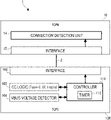
- FIG. 1 is a diagram showing a configuration of a semiconductor system 1 according to the first embodiment.
- the semiconductor system 1 is mounted on a device having a USB port, such as a personal computer and a smartphone.
- the semiconductor system 1 according to the first embodiment has the TCPM 10 (port manager) and a TCPC 100 (port controller).
- the TCPM 10 and the TCPC 100 are communicably connected via an I2C bus 2 (Inter-Integrated Circuit bus).
- the TCPM 10 can be realized by, for example, a microcomputer.
- the TCPC 100 may be mounted on a separate Integrated Circuit from the TCPM 10 . In other words, the TCPM 10 and the TCPC 100 are semiconductor devices.
- the TCPC 100 controls the USB port.
- the TCPM 10 controls the TCPC 100 .
- the TCPC 100 is connected to a USB port (Type-C connector) (not shown in FIG. 1 ).
- the TCPC 100 is provided for each USB port.
- two TCPC 100 can be provided in the semiconductor system 1 . That is, in FIG. 1 , although the semiconductor system 1 has one TCPC 100 , the number of TCPC 100 is not limited to one.
- one TCPM 10 may be provided in the semiconductor system 1 .
- the TCPM 10 may be provided two or more.
- the TCPM 10 includes an interface 12 and a connection detection unit 14 .
- the TCPC 100 has a CC logic 102 , a VBUS voltage detector 104 , an interface 106 , and a controller 110 .
- the controller 110 has a timer 112 .
- the TCPM 10 may have components (e.g., a Policy Engine) related to power Power Delivery (PD).
- PD power Power Delivery
- the TCPC 100 may have a power supply-related component, such as a Physical Layer.
- the interface 12 , the CC logic 102 , the VBUS voltage detector 104 , and the interface 106 are not essential components in the semiconductor system 1 in accordance with present embodiment.
- the interface 12 functions as an I2C master.
- the interface 106 acts as an I2C slave.
- the VBUS voltage detector 104 detects the voltage of VBUS lines (bus voltage lines) of the corresponding USB port.
- the VBUS voltage detector 104 when detecting the voltage of VBUS line, to the controller 110 , and outputs a voltage detection signal.
- the CC logic 102 corresponds to Type-C CC logic in TCPCI specifications (non Patent Document 2).
- the CC logic 102 realizes a state machine.
- the state machine transitions the state (connection state) in the USB port.
- the CC logic 102 according to present embodiment performs at least a process for transition among “disconnected state”, “connection confirmation state”, and “connected state”.
- the “disconnected state” is a state in which there is no connection (via Type-C cable) with an opposite device to the USB port.
- the “connection confirmation state” is a state in which it is confirmed whether or not the USB port is electrically stably connected to the opposite device.
- the “connected state” is a state in which an electrically stable connection is made to the USB port.
- the USB port can act as sink (SNK) or source (SRC) depending on the opposite device. Each connection state then has a different state, depending on whether the USB port functions as a sink or as a source.
- the “disconnected state” may correspond to the “Unattached” state (the “Unattached.SNK” state and the “Unattached.SRC” state) in Type-C specifications (non Patent Document 1).
- the “disconnected state” may correspond to the “Apply Rd” and “Apply Rp” states in TCPCI specifications. Thereafter, the “Apply Rd” and “Apply Rp” states may be collectively referred to as the “Apply” states.
- connection confirmation state may correspond to the “AttachWait” state (the “AttachWait. SNK” state) and the “AttachWait. SRC” state) in Type-C specifications.
- the “connection confirmation state” may correspond to the “Potential_Connect_As_Snk” and “Potential_Connect_As_Src” states in TCPCI specifications. Thereafter, the Potential_Connect_As_Snk state and Potential_Connect_As_Src state are sometimes collectively referred to as the Potential_Connect state.
- the “connected state” may correspond to the “Attached” state (the “Attached.SNK” state and the “Attached.SRC” state) in Type-C specifications.
- the ““connected state”” may correspond to the ““Attached”” state (““Attached. Snk”” and ““Attached. Src”” states) in TCPCI specifications.
- the CC logic 102 controls the CC (Configuration Channel) signals of Type-C connector (USB port) in accordance with Type-C specifications. Then, the CC logic 102 detects the state (connection state) of the USB port. According to Type-C specifications, the CC logic 102 controls the two CC signals (CC 1 signal and CC 2 signal), Rp (Pullup resistor) connection or Rd (Pulldown resistance) connection.
- the opposite device (consumer) having the sink function controls a CC signal to be Rd connection (i.e., on the sink side).
- the CC logic 102 controls the CC signal to the Rd connection
- the voltage of the resistor Rd falls to a ground level, a state in which is not divided by the resistor Rp and the resistor Rd.
- the CC logic 102 does not detect that the opposite device is connected.
- the CC logic 102 controls the CC signal to the Rp connection, the potential in the CC signal is a state of being divided by the resistor Rp and the resistor Rd. At this time, the CC logic 102 detects that the opposite device is connected.
- connection status of the USB port changes from “disconnected state” to “connection confirmation state”.
- the CC logic 102 outputs a state detection signal indicating that the opposite device is connected, that is, the “connection confirmation state” is detected, to the controller 110 .
- an opposite device having a source function controls the CC signal to be Rp-connected (i.e., on the source side).
- the CC logic 102 controls the CC signal to the Rp connection, the voltage of the resistor Rp becomes a high state, a state in which is not divided by the resistor Rp and the resistor Rd. At this time, the CC logic 102 does not detect that the opposite device is connected.
- the CC logic 102 controls the CC signal to the Rd connection, the potential in the CC signal is a state of being divided by the resistor Rp and the resistor Rd. At this time, the CC logic 102 detects that the opposite device is connected.
- connection status of the USB port changes from “disconnected state” to “connection confirmation state”.
- the CC logic 102 outputs a state detection signal indicating that the opposite device is connected, that is, the “connection confirmation state” is detected, to the controller 110 .
- the controller 110 controls the transition of the connection state in the USB port. That is, the controller 110 controls the transition in the state machine.
- the controller 110 outputs a connected state transition notification (Attached state transition notification) when the connected state transitions to the connected state (Attached state).
- the connected state transition notification is transmitted to the connection detection unit 14 via the interface 106 , the I2C bus 2 , and the interface 12 .
- the connected state transition notification may indicate whether the USB port functions as a sink or as a source.
- the controller 110 when receiving a state detection signal indicating that it has detected the “connection confirmation state” from the CC logic 102 , using the timer 112 , to measure the duration of the connection confirmation state. That is, the timer 112 measures the time from when the connection state transitions from the disconnected state to the connection confirmation state. Then, when the duration of the connection confirmation state has elapsed a predetermined period of time, i.e., the first period of time, the controller 110 transitions the connection state to the connected state. At this time, the controller 110 outputs the connected state transition notification.
- the controller 110 when the duration of the connection confirmation state has elapsed the first time, and when receiving a voltage detection signal, the controller 110 may transition to the connection state to the connected state.
- the connection to the USB port is released before the duration of the connection confirmation state elapses a predetermined period of time, i.e., the first period of time, the controller 110 may transition the connection state to the disconnected state.
- the connection detection unit 14 receives the connected state transition notification and detects the connection of the USB port. That is, the connection detection unit 14 detects that the USB port and the opposite device are electrically stably connected to each other. In addition, the connection detection unit 14 detections whether the USB port functions as a sink or as a source. At this time, the TCPM 10 performs processing corresponding to the connection detected by the connection detection unit 14 , for example, processing relating to at least one of power receiving and power supply. Specifically, the TCPM 10 controls a power supply circuit or performs a Power Delivery process. Thus, if the USB port functions as a sink, power is supplied to the device on which the semiconductor system 1 is mounted via the USB port. Further, when the USB port functions as a source, the device on which the semiconductor system 1 is mounted provides power to the opposite device connected to the USB port.
- FIGS. 2 and 3 are diagrams illustrating state transition diagrams realized in the semiconductor system 1 according to the first embodiment.
- FIGS. 2 and 3 illustrate state transition diagrams for Dual Role Power devices in accordance with TCPCI specifications.
- descriptions of states and transitions unrelated to present embodiment are appropriately omitted.
- FIG. 2 shows a state transition diagram until the connected state transitions to the connected state.
- the state machine (connected state) alternately transitions between the “Apply Rd” state St 101 (disconnected state) and the “Apply Rp” state St 102 (disconnected state) at regular intervals. That is, the state machine toggles the state between the “Apply Rd” state St 101 and the “Apply Rp” state St 102 at regular intervals.
- the “Apply Rd” state St 101 is a state in which the CC signal of the CC signal itself is controlled to be connected to the Rd signal.
- the “Apply Rp” state St 102 is a state in which the CC signal of the CC signal itself is controlled to be connected to the Rp signal.
- the state machine When the state machine is in the “Apply Rd” state St 101 , it is assumed that an opposite device having a source function is connected to the USB port, and the potential of the CC signal is divided as described above. Then, as described above, the state machine transitions to the “Potential_Connect_As_Snk” state St 111 . In this state, when the opposite device having a source function is removed from the USB port, the state machine enters the “Apply Rp” state St 102 . On the other hand, when the state in which the potential in the CC signal is divided continues for a first time (tCCDebounce) and the voltage of VBUS line is detected, the state machine transitions to the “Attached. Snk” state St 121 .
- FIG. 3 shows a state transition diagram from the connected state to the disconnected state. Assume that, when the state machine is in the “Attached.Snk” state St 121 , the voltages of VBUS lines are not detected, and the disconnection with the opposite device having the source function is detected. The state machine then transitions to the “Disconnected_As_Snk” state St 131 . The state machine then unconditionally transitions to the “Apply Rd” state St 101 .
- FIGS. 4 and 5 are sequence diagrams showing processes executed by the semiconductor system 1 according to the first embodiment.
- the TCPM 10 initializes and the State Machine starts (step S 102 ).
- the state machine is then toggled between the “Apply Rp” and “Apply Rd” states.
- the state machine transitions to the “Potential_Connect_As_Snk” state or the “Potential_Connect_As_Src” state.
- the controller 110 of the TCPC 100 determines whether or not the connection confirmation state has continued for the first time (step S 104 ). If the connection confirmation state does not continue for the first time (NO, in S 104 ), the controller 110 controls the state machine to transition to the “Apply Rp” state or the “Apply Rd” state (step S 105 ).
- connection confirmation state continues for the first time (YES, in S 104 )
- the controller 110 controls the state machine so that the state transitions to the connected state.
- the state machine transitions to the “Attached.Snk” state or the “Attached.Src” state.
- the controller 110 transmits to the TCPM 10 a notification indicating that the connected state has changed to the connected state.
- the connection detection unit 14 receives this notification, the TCPM 10 executes a process in the “Attached.Snk” state or the “Attached.Src” state (step S 108 ).
- the TCPC 100 notifies the detection of VbusSinkDisconnected or a change in the status of the CC signal to the TCPM 10 (step S 112 ).
- the TCPC 100 then switches off VBUS and discharges VBUS, step S 114 .
- the state machine then transitions to the “Apply Rd” state and then toggles between the “Apply Rp” and “Apply Rd” states.
- FIG. 6 is a diagram showing a configuration of a semiconductor system 80 according to the comparative example.
- Semiconductor system 80 includes a TCPM 90 (a port manager) and a TCPC 82 (a port controller).
- the TCPM 90 and the TCPC 82 are communicably connected via the I2C bus 2 .
- the comparative examples correspond to system conforming to TCPCI specifications.
- the TCPM 90 includes the interface 12 and a TCPC state controller 92 .
- the TCPC 82 includes the CC logic 102 , the VBUS detector 104 , and the interface 106 .
- the TCPC 82 according to the comparative embodiment differs from the TCPC 100 according to the first embodiment in that it does not have the controller 110 .
- the TCPM 90 according to the comparative embodiment differs from the TCPM 10 according to the first embodiment in that it does not have the connection detection unit 14 but has the TCPC state controller 92 .
- Other components are substantially the same as those associated with the first embodiment.
- FIGS. 7 and 8 are sequence diagrams showing processing executed by the semiconductor system 80 according to the comparative example.
- the TCPM 90 zero times and the State Machine starts (step S 902 ).
- the state machine is then toggled between the “Apply Rp” and “Apply Rd” states.
- the state machine transitions to the “Potential_Connect_As_Snk” state or the “Potential_Connect_As_Src” state.
- the TCPC 82 notifies the TCPM 90 of a change in the status (CC status) of the CC signals (step S 904 ).
- the TCPC state controller 92 of the TCPM 90 reads the CC status for tCCDebounce period via the I2C bus 2 (step S 906 ). Specifically, the TCPC state controller 92 accesses the CC status register of the TCPC 82 to read the CC status.
- the TCPC state controller 92 determines whether or not connection confirmation state has continued for tCCDebounce period in step S 908 .
- the TCPC state controller 92 transmits an instruction to the TCPC 82 to transition to the “Apply Rp” state or the “Apply Rd” state (step S 909 ).
- the state machine then transitions through the “Maintain State” ( FIG. 3 ) to the “Apply Rp” or “Apply Rd” state.
- the TCPC state controller 92 transmits to the TCPC 82 an instruction to transition to the connected state (step S 910 ). Specifically, the TCPC state controller 92 accesses the CC status register of the TCPC 82 to write the control content. This causes the state machine to transition to the “Attached. Snk” state or the “Attached. Src” state through the “MAINTAIN_STATE” ( FIG. 3 ). The TCPM 90 performs operations in the “Attached. Snk” or “Attached. Src” state (step S 912 ).
- the TCPC 82 notifies the detection of VbusSinkDisconnected or of a change of the status of the CC signal to the TCPM 90 (step S 914 ). the TCPC 82 then switches off VBUS and discharges VBUS, step S 916 .
- the TCPM 90 (TCPC state controller 92 ) receives the notification and transmits an instruction that changes the state to “Apply Rd” to the TCPC 82 (step S 918 ). This causes the state machine to transition to the “Apply Rd” state through the “Maintain State” ( FIG. 3 ). The state machine then toggles between the “Apply Rp” and “Apply Rd” states.
- the TCPM 90 (TCPC state controller 92 ) accesses the TCPC 82 registers through the I2C bus 2 , thereby transiting the state machine to the connected state.
- the communication time may increase. Therefore, since the communication time further increases as the number of ports increases, it is difficult to increase the number of ports in the system according to the comparative example.
- AC adapters for Type-A connectors there are many products with more than four ports. Therefore, it is desirable to increase the number of ports even in Type-C products.
- present embodiment is configured as described above so that the TCPC 100 can change the state machine to the connected state in the process of connecting the USB port.
- present embodiment allows the state machine to transition to the connected state without the TCPM 10 intervention in the connection process on the USB port.
- This makes it possible to reduce the communication time through the I2C bus 2 .
- present embodiment can reduce the amount of time it takes to process a connection to a USB port in connection processing to the USB port. As a result, even if the number of ports is increased, it is possible to suppress an increase in processing time.
- the controller 110 of the first embodiment uses the timer 112 to measure the duration of the connection check status in which the USB port is connected to the USB port. Then, the controller 110 transitions the connected state to the connected state when the duration has elapsed a predetermined first period of time (tCCDebounce period). This allows the TCPC 100 to efficiently transition state machines to the connected state without the TCPM 10 intervention.
- the controller 110 on the first embodiment transits the connection state to the disconnected state. This allows the state machine to go to the disconnected state without the TCPM intervention. Therefore, even when the state machine is shifted to the disconnected state, the communication time through the I2C bus 2 can be reduced.
- FIGS. 9 to 12 are diagrams showing another example of the state transition diagram realized in the semiconductor system 1 according to the first embodiment.
- states and transitions unrelated to present embodiment will be omitted as appropriate.
- FIG. 9 illustrates a state-transition diagram for DRP devices that conform to Type-C specifications.
- the state machine (connected state) alternately transitions between the “Unattached.SNK” state St 201 and the “Unattached.SRC” state St 202 at regular intervals. That is, the state machine toggles states between the “Unattached.SNK” state St 201 and the “Unattached.SRC” state St 202 at regular intervals.
- the “Unattached. SNK” state and the “Unattached. SRC” state correspond to the “disconnected state” described above.
- the “Unattached.SNK” state St 201 is a state in which the CC signal of the CC signal itself is controlled to be connected to the Rd signal. In the “Unattached.SRC” state St 202 , its own CC signal is controlled to be connected to the Rp signal.
- the state machine transitions to the “AttachWait.SNK” state St 211 .
- the “AttachWait.SNK” state corresponds to the “connection confirmation state” described above.
- the controller 110 measures the time from the transition to the “AttachWait.SNK” state St 211 by using the timer 112 .
- the state machine transitions to the “Unattached.SRC” state St 202 under the control of the controller 110 .
- the state in which the potential in the CC signal is divided is continued for a first time (tCCDebounce), the voltage of VBUS line is detected.
- the state machine transitions to the “Attached.SNK” state St 221 .
- the “Attached.SNK” state corresponds to the “connected state” described above.
- the state machine transitions to the “Unattached.SNK” state St 201 .
- the state machine transitions to the “AttachWait.SRC” state St 212 .
- the “AttachWait.SRC” state corresponds to the “connection confirmation state” described above.
- the controller 110 measures the time from the transition to the “AttachWait.SNK” state St 211 by using the timer 112 .
- FIGS. 10 and 11 illustrate state-transition diagrams for Try.SRC devices corresponding to TCPCI specifications.
- FIG. 10 shows a state transition diagram until the connection state transitions to the connected state.
- the Try.SRC device is a DRP device that acts as a source when connecting to other DRP devices.
- FIGS. 10 and 11 an example of the Try.SRC device is shown in FIGS. 10 and 11 , the same applies to the Try.SNK device.
- the Try.SNK device is a DRP device that acts as a sink when connecting to other DRP devices.
- the “Apply Rd” state St 301 and the “Apply Rp” state St 302 shown in FIG. 10 are substantially the same as St 101 and St 102 shown in FIG. 2 , respectively.
- the “Potential_Connect_As_Snk” state St 311 shown in FIG. 10 is substantially the same as St 111 shown in FIG. 2 .
- the “Potential_Connect_As_Src” state St 312 shown in FIG. 10 is substantially the same as St 112 shown in FIG. 2 .
- the “Attached.Snk” state St 321 shown in FIG. 10 is substantially the same as St 121 shown in FIG. 2 .
- the “Attached.Src” state St 322 shown in FIG. 10 is substantially the same as St 122 shown in FIG. 2 .
- the transition between St 301 and St 302 shown in FIG. 10 is substantially similar to the transition between St 101 and St 102 shown in FIG. 2 .
- the transition from St 301 to St 311 shown in FIG. 10 is substantially the same as the transition from St 101 to St 111 shown in FIG. 2 .
- the transition from St 302 to St 312 shown in FIG. 10 is substantially the same as the transition from St 102 to St 112 shown in FIG. 2 .
- the transition from St 311 to St 302 shown in FIG. 10 is substantially the same as the transition from St 111 to St 102 shown in FIG. 2 .
- the transition from St 312 to St 301 shown in FIG. 10 is substantially the same as the transition from St 112 to St 101 shown in FIG. 2 .
- the transition from St 312 to St 322 shown in FIG. 10 is substantially the same as the transition from St 112 to St 122 shown in FIG. 2 .
- the state machine transitions to the “Try.SRC” state St 316 .
- the TCPC 100 will check if the opposite device connected to the USB port has a sink function.
- the device connects a resistor Rp to the CC signals, and the state machine confirms whether the opposing device makes an Rd connection or not.
- the controller 110 when it is St 311 , a state in which the potential in the CC signal is divided is continued for a tCCDebounce period, determines whether the voltage of VBUS line is detected. Then, the state in which the potential in the CC signal is divided continues for a tCCDebounce period, when the voltage of VBUS line is detected, the controller 110 transits the connection state to the opposite device confirmation state (St 316 ).
- the state machine When the state machine is in the “Try.SRC” state St 316 , the CC signals of the opposite device are Rd-connected during tTryCCDebounce period to divide the potential, and the sink is detected. At this time, under the control of the controller 110 , the state machine transitions to the “Attached.Src” state St 322 . That is, the controller 110 , when it is St 316 , when the opposite device detects that it has a power receiving function (specific function; first function) is tTryCCDebounce period (second time) continues, to transit the connection state to the connected state.
- a power receiving function specific function; first function
- the state machine when the state machine is in the “Try.SRC” state St 316 , it is assumed that no sink is detected after tDRPTry period has elapsed and the voltage of VBUS line is vSafe0V. At this time, under the control of the controller 110 , the state machine transitions to the “TryWait.SNK” state St 318 . In this St 318 , the state machine waits for the USB port to be connected as sinks. That is, the controller 110 , when it is St 316 , when the opposite device side after tDRPTry time (third time) elapses is not detected that has a power receiving function, the connection state to transit to “TryWait. SNK”.
- the controller 110 when it is St 316 , after the lapse of the third time, when the opposite device side does not detect that it has a specific function, transits the connection state to the “specific function standby state”.
- “specific function state state” is a state in which the USB port is waiting for a specific function.
- the device connects the CC signal to the resistor Rd, and the state machine determines whether or not the counterpart device makes the Rp connection.
- the state machine transitions to the “Attached.Snk” state St 321 .
- the state machine transitions to the “Apply Rd” state St 301 under the control of the controller 110 .
- the controller 110 when it is St 318 , when the state of detecting that the opposite device side has a power supply function continues for a tCCDebounce period, transits the connection state to the “connected state”.
- the controller 110 when it is St 318 , when the state in which the opposite device side is not detecting that it has a power supply function continues for a tPDDebounce period (fourth time), transits the connection state to the “disconnected state”.
- FIG. 11 shows a state transition diagram from a connected state to a disconnected state.
- the “Disconnected_As_Snk” state St 331 shown in FIG. 11 is substantially the same as St 131 shown in FIG. 3 .
- the “Disconnected_As_Src” state St 332 shown in FIG. 11 is substantially the same as St 132 shown in FIG. 3 .
- the transition from St 321 to St 331 shown in FIG. 11 is substantially the same as the transition from St 121 to St 131 shown in FIG. 2 .
- the transition from St 322 to St 332 shown in FIG. 11 is substantially the same as the transition from St 122 to St 132 shown in FIG. 2 .
- the transition from St 331 to St 301 shown in FIG. 11 is substantially the same as the transition from St 131 to St 101 shown in FIG. 2 .
- FIG. 12 illustrates a state transition diagram for Try.SRC device corresponding to Type-C specifications.
- the “Unattached.SNK” state St 401 and the “Unattached.SRC” state St 402 shown in FIG. 12 are substantially the same as St 201 and St 202 shown in FIG. 9 , respectively.
- the “AttachWait.SNK” state St 411 shown in FIG. 12 is substantially the same as St 211 shown in FIG. 9 .
- the “AttachWait.SRC” state St 412 shown in FIG. 12 is substantially the same as St 212 shown in FIG. 9 .
- the “Attached.SNK” state St 421 shown in FIG. 12 is substantially the same as St 221 shown in FIG. 9 .
- the “Attached.SRC” state St 422 shown in FIG. 12 is substantially the same as St 222 shown in FIG. 9 .
- the transition between St 401 and St 402 shown in FIG. 12 is substantially the same as the transition between St 2101 and St 202 shown in FIG. 9 .
- the transition from St 401 to St 411 shown in FIG. 12 is substantially the same as the transition from St 201 to St 211 shown in FIG. 9 .
- the transition from St 402 to St 412 shown in FIG. 12 is substantially the same as the transition from St 202 to St 212 shown in FIG. 9 .
- the transition from St 411 to St 402 shown in FIG. 12 is substantially the same as the transition from St 211 to St 202 shown in FIG. 9 .
- the transition from St 412 to St 401 shown in FIG. 12 is substantially the same as the transition from St 212 to St 201 shown in FIG. 9 .
- the transition from St 412 to St 422 shown in FIG. 12 is substantially the same as the transition from St 212 to St 222 shown in FIG. 9 .
- the transition from St 421 to St 401 shown in FIG. 12 is substantially the same as the transition from St 221 to St 201 shown in FIG. 9 .
- the state machine when the state machine is in the “AttachWait. SNK” state St 411 , the potential in the CC signal continues for a tCCDebounce period and the voltage in VBUS line is detected. At this time, under the control of the controller 110 , the state machine transitions to the “Try.SRC” state St 416 . In this St 416 , the TCPC 100 will check if the opposite device connected to the USB port has a sink function.
- the state machine When the state machine is in the “Try.SRC” state St 416 , the CC signals of the opposite device is Rd connection during tTryCCDebounce period to divide the potential, and the sink is detected. At this time, under the control of the controller 110 , the state machine transitions to the “Attached.SRC” state St 422 .
- the state machine when the state machine is in the “Try.SRC” state St 416 , no sinks are detected in tDRPTry periods, and the voltages of VBUS lines are vSafe0V. At this time, under the control of the controller 110 , the state machine transitions to the “TryWait.SNK” state St 418 . In this St 418 , the state machine waits for the USB port to be connected as sinks.
- a controller 110 in the TCPC 100 state transitions in any state machine can be performed by the TCPC 100 without the TCPM 10 intervention. This makes it possible to reduce the communication time through the I2C bus 2 . Accordingly, present embodiment can reduce the processing time for connection processing to the USB port for the semiconductor system 1 with respect to any state machine during connection processing to the USB port. As a result, even if the number of ports is increased, it is possible to suppress the processing time from being applied to the image.
- the above-described specific function may be a power supply function. Then, the controller 110 performs processing for the “Try.SNK” state instead of the processing for the “Try.SRC” state described above. Similarly, the controller 110 performs processing for the “TryWait. SRC” state instead of the processing for the “TryWait. SNK” state described above.
- Semiconductor system in the second embodiment differ from semiconductor system in the first embodiment in that the TCPC 100 controls the power supply circuitry.
- the rest of the configuration is substantially the same as the configuration according to the first embodiment.
- FIG. 13 is a diagram showing a configuration of the semiconductor system 1 according to the second embodiment.
- the semiconductor system 1 according to the second embodiment includes the TCPM 10 and a port IC 20 .
- the TCPM 10 and the port IC 20 are communicably connected via the I2C bus 2 .
- the configuration of the TCPM 10 for the second embodiment is essentially the same as the configuration of the TCPM 10 for the first embodiment.
- a port IC 20 is provided for each USB port.
- the port IC 20 handles the corresponding USB port.
- the port IC 20 include the TCPC 100 and power supply circuit 22 .
- the configuration of the TCPC 100 according to the second embodiment is substantially the same as the configuration of the TCPC 100 according to the first embodiment.
- Power supply circuit 22 performs at least one of the power receiving and power supply.
- the controller 110 of the TCPC 100 controls the power supply circuit 22 when the connected state transitions to the connected state. In present embodiment, the controller 110 transitions the connected state to the connected state, so that the controller 110 can directly control the power supply circuit 22 instead of the TCPM 10 circuit.
- the controller 110 when the connection state transitions to the “Attached. SNK” state, the controller 110 , so that the power receiving process to the power supply circuit 22 , controls the power supply circuit 22 .
- the control of the controller 110 the power supply circuit 22 turns on the switch of VBUS power receiving circuit, to enable VBUS power receiving circuit.
- the device on which the semiconductor system 1 is mounted power is supplied from the opposite device.
- the controller 110 when the connection state transitions to the “Attached. SRC” state, the controller 110 , so as to power the power supply circuit 22 , controls the power supply circuit 22 . In this case, the control of the controller 110 , the power supply circuit 22 outputs VBUS to the opposite device. Furthermore, when VCONN is supported, the power supply circuitry 22 outputs VCONN to the cables.
- the power supply circuit 22 is incorporated in the port IC 20
- present embodiment is not limited to such a configuration.
- the power supply circuit 22 may not be built in the port IC 20 , but may be external to the port IC 20 .
- the power supply circuit 22 may be connected to the port IC 20 (TCPC 100 ) via a gate control signal line or the like.
- controller 110 when the connection state transitions to the connected state, via a bus, transmits a control signal to the power supply circuit 22 .
- Power supply circuit 22 receives a control signal, performs power receiving treatment or power supply processing according to the control signal.
- the semiconductor system 1 according to the second embodiment is capable of transitioning the state machine to the connected state without involving the TCPM 10 in the connecting process in the USB port. This makes it possible to reduce the communication time through the I2C bus 2 . Therefore, the semiconductor system 1 of the second embodiment can have substantially the same effects as those on the first embodiment.
- the controller 110 provided on the TCPC 100 controls the power supply circuit 22 .
- the TCPC 100 can directly control the power supply circuit 22 without involvement of the TCPM 10 . Therefore, as compared to when the TCPM 10 controls the power supply circuit 22 , efficiently, it is possible to control the power supply circuit 22 . In other words, as compared to when the TCPM 10 controls the power supply circuitry 22 , efficiently, it is possible to perform the power receiving process or power supply process.
- the third embodiment differs from the other embodiments in that it is considered that Type-C specification or TCPCI specification (hereinafter referred to as the “Type-C specification, etc.”) is updated.
- Type-C specifications and the like may be updated after the semiconductor system 1 according to present embodiment is mounted on the semiconductor system 1 .
- state addition, change of transition conditions, and the like in the state machine may be performed.
- the semiconductor system 1 according to the third embodiment is configured to be able to cope with such a case.
- FIG. 14 is a diagram showing a configuration of the semiconductor system 1 according to the third embodiment. Similar to the semiconductor system 1 related to the first embodiment, the semiconductor system 1 related to third embodiment has the TCPM 10 and the TCPC 100 .
- the TCPM 10 includes interface 12 , the connection detection unit 14 , and a state controller 16 .
- the TCPM 10 required for the third embodiment differs from TCPM 10 of the other embodiments in that it has the state controller 16 .
- Other configurations of the TCPM 10 according to the third embodiment are substantially the same as those of the TCPM 10 according to the other embodiments.
- the state controller 16 performs substantially the same process as the TCPC state controller 92 when receiving a notification from the TCPC 100 . Details will be described later.
- the TCPC 100 has the CC logic 102 , the VBUS voltage detector 104 , the interface 106 , and the controller 110 .
- the controller 110 includes the timer 112 and the register 114 .
- the TCPC 100 required for the third embodiment differs from the TCPC 100 of other embodiments in that the controller 110 has the register 114 .
- Other configurations of the TCPC 100 according to the third embodiment are substantially the same as those of the TCPC 100 according to the other embodiments.
- the register 114 sets a predetermined state (first state) in the state machine.
- the first state (set state) set in the register 114 corresponds to the state about the state or transition condition changed in the state machine when Type-C specifications, etc. are updated. Details will be described later.
- FIG. 15 is a flow chart showing control methods executed by the controller 110 according to the third embodiment.
- the controller 110 sets a predetermined state in the register 114 (Step S 300 ).
- the setting state can be the state from which the added state transitions.
- the setting state may be a state which is a transition source of the changed transition condition.
- the controller 110 determines whether or not the connected state (state machine) has transitioned to the set state (step S 302 ).
- the controller 110 stops the state machine (Step S 304 ). That is, the controller 110 has a function of stopping the state machine when the connection state transitions to the first state.
- step S 306 the controller 110 transmits a notification indicating that the state machine has been stopped to the outside. That is, the controller 110 has a function of notifying the outside that the state machine has been stopped.
- the process in TCPM 10 begins. Specifically, the state controller 16 controls the state or the transition condition changed in the updated Type-C specifications or the like.
- step S 308 the controller 110 determines whether or not the process in the above-described the TCPM 10 has been completed.
- the controller 110 restarts the state machine from the state controlled by the state controller 16 or the state of the transition destination of the transition condition (Step S 310 ).
- the controller 110 can perform control relating to the state or the transition condition that has not been changed in the same manner as in the above-described embodiment.
- the controller 110 sets the “Try.SRC” state St 316 in the register 114 as the setting state (S 300 ).
- the controller 110 stops the state machine (S 304 ).
- the state controller 16 performs control relating to the newly added state.
- the controller 110 restarts the state machine from the state to which the added state is transferred (S 310 ). That is, the controller 110 restarts the state machine from the “TryWait.SNK” state St 318 .
- the controller 110 sets the “TryWait.SNK” state St 318 in the register 114 as the setting state (S 300 ).
- the controller 110 stops the state machine (S 304 ).
- the state controller 16 performs a process of determining the changed transitional condition.
- the controller 110 restarts the state machine from the state to which the transition condition was changed (S 310 ). That is, the controller 110 restarts the state machine from the “Apply Rd” state St 301 .
- the semiconductor system 1 according to the third embodiment is capable of transitioning the state machine to the connected state without involving the TCPM 10 in the connecting process in the USB port. This makes it possible to reduce the communication time through the I2C bus 2 . Therefore, the semiconductor system 1 of the third embodiment can have substantially the same effects as those on the first embodiment.
- the controller 110 stops the state machine and transmits a notification that the state machine has been stopped to the outside.
- the TCPM 10 can control the changed state or transition condition.
- it is unnecessary to reimplement the controller 110 of the hardware mounted on the TCPC 100 .
- the controller 110 restarts the state machine from the state (connected state) controlled by the state controller 16 or the state of the transition destination of the transition condition.
- the TCPC 100 can continue to process the state or transition condition that has not been changed. Therefore, even when Type-C specifications and the like are updated, the semiconductor system 1 according to the third embodiment can exhibit the effects of the semiconductor system 1 according to first embodiment.
- the controller 110 includes the register 114 for setting the setting state.
- the original state of the changed part can be arbitrarily set. Therefore, the semiconductor system 1 according to present embodiment can be flexibly applied to any updates such as Type-C specifications.
- the state machine realized by the TCPC 100 according to present embodiment is not limited to the state machine illustrated in FIG. 2 , FIG. 3 , and FIG. 9 to FIG. 12 .
Landscapes
- Engineering & Computer Science (AREA)
- Theoretical Computer Science (AREA)
- General Engineering & Computer Science (AREA)
- Physics & Mathematics (AREA)
- General Physics & Mathematics (AREA)
- Computer Hardware Design (AREA)
- Microelectronics & Electronic Packaging (AREA)
- Information Transfer Systems (AREA)
Abstract
Description
- [Non Patent Document 1] Universal Serial Bus Type-C Cable and Connector Specification, Release 1.4, Mar. 29, 2019
- [Non Patent Document 2] Universal Serial Bus Type-CTM Port Controller Interface Specification, Revision 2.0, Version 1.0, October 2017
Claims (18)
Applications Claiming Priority (3)
| Application Number | Priority Date | Filing Date | Title |
|---|---|---|---|
| JP2019099978A JP7213755B2 (en) | 2019-05-29 | 2019-05-29 | Semiconductor system and semiconductor device |
| JP2019-099978 | 2019-05-29 | ||
| JPJP2019-099978 | 2019-05-29 |
Publications (2)
| Publication Number | Publication Date |
|---|---|
| US20200379937A1 US20200379937A1 (en) | 2020-12-03 |
| US11288224B2 true US11288224B2 (en) | 2022-03-29 |
Family
ID=73507086
Family Applications (1)
| Application Number | Title | Priority Date | Filing Date |
|---|---|---|---|
| US16/860,915 Active US11288224B2 (en) | 2019-05-29 | 2020-04-28 | Semiconductor system and semiconductor device |
Country Status (3)
| Country | Link |
|---|---|
| US (1) | US11288224B2 (en) |
| JP (1) | JP7213755B2 (en) |
| CN (1) | CN112015682B (en) |
Families Citing this family (2)
| Publication number | Priority date | Publication date | Assignee | Title |
|---|---|---|---|---|
| US20220276687A1 (en) * | 2019-10-15 | 2022-09-01 | Hewlett-Packard Development Company, L.P. | Port role assignments |
| TW202411853A (en) * | 2022-09-01 | 2024-03-16 | 宏碁股份有限公司 | Electronic system using usb type-c port and abnormal elimination method thereof |
Citations (21)
| Publication number | Priority date | Publication date | Assignee | Title |
|---|---|---|---|---|
| US4835737A (en) * | 1986-07-21 | 1989-05-30 | American Telephone And Telegraph Company, At&T Bell Laboratories | Method and apparatus for controlled removal and insertion of circuit modules |
| US5386567A (en) * | 1992-01-20 | 1995-01-31 | International Business Machines Corp. | Hot removable and insertion of attachments on fully initialized computer systems |
| US5644731A (en) * | 1995-07-07 | 1997-07-01 | Sun Microsystems, Inc. | Method and apparatus for hot plugging/unplugging a sub-system to an electrically powered system |
| US5664118A (en) * | 1994-03-28 | 1997-09-02 | Kabushiki Kaisha Toshiba | Computer system having detachable expansion unit |
| US5721836A (en) * | 1994-01-27 | 1998-02-24 | Compaq Computer Corporation | Method and apparatus for sensing and changing the state of a computer before connecting the computer to or disconnecting the computer from an expansion unit |
| US5787261A (en) * | 1994-11-28 | 1998-07-28 | Hitachi, Ltd | Data transfer system, computer system and active-line inserted/withdrawn functional circuit board |
| US5790958A (en) * | 1995-10-16 | 1998-08-04 | Mmgt Enterprises, Inc. | Radio reception system for general purpose computer |
| US6073196A (en) * | 1996-06-05 | 2000-06-06 | Compaq Computer Corporation | Using communication cycles for connecting and disconnecting devices in a computer system |
| US6662119B1 (en) * | 2002-08-02 | 2003-12-09 | 3Com Corporation | Method and apparatus for monitoring connector degradation |
| US20060066573A1 (en) * | 2004-09-24 | 2006-03-30 | Fujitsu Limited | Device control system |
| US20080005258A1 (en) * | 2006-06-30 | 2008-01-03 | Microsoft Corporation | Efficiently polling to determine completion of a DMA copy operation |
| US7414335B2 (en) * | 2004-04-15 | 2008-08-19 | Seagate Technology | Inrush current controller |
| US20110131344A1 (en) * | 2009-11-27 | 2011-06-02 | Samsung Electronics Co., Ltd. | Terminal apparatus and method for controlling usb apparatus thereof |
| US20120246523A1 (en) * | 2011-03-25 | 2012-09-27 | Adc Telecommunications, Inc. | Dynamically detecting a defective connector at a port |
| US20140208134A1 (en) * | 2013-01-21 | 2014-07-24 | Texas Instruments Incorporated | Host controller interface for universal serial bus (usb) power delivery |
| US20150309954A1 (en) * | 2014-04-29 | 2015-10-29 | Mcci Corporation | Apparatus and methods for dynamic role switching among usb hosts and devices |
| US20170139467A1 (en) * | 2015-11-13 | 2017-05-18 | Texas Instruments Incorporated | Usb interface circuit and method for low power operation |
| US20180148045A1 (en) * | 2016-11-30 | 2018-05-31 | Mando Corporation | Driver assistance system having controller and controlling method thereof |
| US20180189223A1 (en) * | 2016-12-31 | 2018-07-05 | Intel Corporation | Universal serial bus type-c power delivery |
| US20190213159A1 (en) * | 2018-01-11 | 2019-07-11 | Nuvoton Technology Corporation | Universal serial bus type-c interface circuit and pin bypass method thereof |
| US20200119540A1 (en) * | 2018-10-11 | 2020-04-16 | Texas Instruments Incorporated | Usb short circuit protection |
Family Cites Families (5)
| Publication number | Priority date | Publication date | Assignee | Title |
|---|---|---|---|---|
| US7447874B1 (en) * | 2005-10-18 | 2008-11-04 | Qlogic, Corporation | Method and system for designing a flexible hardware state machine |
| US8843664B2 (en) * | 2011-09-29 | 2014-09-23 | Cypress Semiconductor Corporation | Re-enumeration of USB 3.0 compatible devices |
| JP6936543B2 (en) | 2015-11-13 | 2021-09-15 | テキサス インスツルメンツ インコーポレイテッド | USB interface circuits and methods for low power operation |
| JP2017187933A (en) * | 2016-04-06 | 2017-10-12 | ルネサスエレクトロニクス株式会社 | SEMICONDUCTOR DEVICE, SEMICONDUCTOR DEVICE CONTROL METHOD, AND POWER SUPPLY SYSTEM |
| TWI683198B (en) * | 2018-09-14 | 2020-01-21 | 威鋒電子股份有限公司 | Multi-port power supply apparatus and power suppling method thereof |
-
2019
- 2019-05-29 JP JP2019099978A patent/JP7213755B2/en active Active
-
2020
- 2020-04-28 US US16/860,915 patent/US11288224B2/en active Active
- 2020-05-28 CN CN202010469522.1A patent/CN112015682B/en active Active
Patent Citations (22)
| Publication number | Priority date | Publication date | Assignee | Title |
|---|---|---|---|---|
| US4835737A (en) * | 1986-07-21 | 1989-05-30 | American Telephone And Telegraph Company, At&T Bell Laboratories | Method and apparatus for controlled removal and insertion of circuit modules |
| US5386567A (en) * | 1992-01-20 | 1995-01-31 | International Business Machines Corp. | Hot removable and insertion of attachments on fully initialized computer systems |
| US5721836A (en) * | 1994-01-27 | 1998-02-24 | Compaq Computer Corporation | Method and apparatus for sensing and changing the state of a computer before connecting the computer to or disconnecting the computer from an expansion unit |
| US5664118A (en) * | 1994-03-28 | 1997-09-02 | Kabushiki Kaisha Toshiba | Computer system having detachable expansion unit |
| US5787261A (en) * | 1994-11-28 | 1998-07-28 | Hitachi, Ltd | Data transfer system, computer system and active-line inserted/withdrawn functional circuit board |
| US5644731A (en) * | 1995-07-07 | 1997-07-01 | Sun Microsystems, Inc. | Method and apparatus for hot plugging/unplugging a sub-system to an electrically powered system |
| US5790958A (en) * | 1995-10-16 | 1998-08-04 | Mmgt Enterprises, Inc. | Radio reception system for general purpose computer |
| US6073196A (en) * | 1996-06-05 | 2000-06-06 | Compaq Computer Corporation | Using communication cycles for connecting and disconnecting devices in a computer system |
| US6662119B1 (en) * | 2002-08-02 | 2003-12-09 | 3Com Corporation | Method and apparatus for monitoring connector degradation |
| US7414335B2 (en) * | 2004-04-15 | 2008-08-19 | Seagate Technology | Inrush current controller |
| US20060066573A1 (en) * | 2004-09-24 | 2006-03-30 | Fujitsu Limited | Device control system |
| US20080005258A1 (en) * | 2006-06-30 | 2008-01-03 | Microsoft Corporation | Efficiently polling to determine completion of a DMA copy operation |
| US20110131344A1 (en) * | 2009-11-27 | 2011-06-02 | Samsung Electronics Co., Ltd. | Terminal apparatus and method for controlling usb apparatus thereof |
| US8612634B2 (en) * | 2009-11-27 | 2013-12-17 | Samsung Electronics Co., Ltd. | Terminal apparatus and method for controlling USB apparatus thereof |
| US20120246523A1 (en) * | 2011-03-25 | 2012-09-27 | Adc Telecommunications, Inc. | Dynamically detecting a defective connector at a port |
| US20140208134A1 (en) * | 2013-01-21 | 2014-07-24 | Texas Instruments Incorporated | Host controller interface for universal serial bus (usb) power delivery |
| US20150309954A1 (en) * | 2014-04-29 | 2015-10-29 | Mcci Corporation | Apparatus and methods for dynamic role switching among usb hosts and devices |
| US20170139467A1 (en) * | 2015-11-13 | 2017-05-18 | Texas Instruments Incorporated | Usb interface circuit and method for low power operation |
| US20180148045A1 (en) * | 2016-11-30 | 2018-05-31 | Mando Corporation | Driver assistance system having controller and controlling method thereof |
| US20180189223A1 (en) * | 2016-12-31 | 2018-07-05 | Intel Corporation | Universal serial bus type-c power delivery |
| US20190213159A1 (en) * | 2018-01-11 | 2019-07-11 | Nuvoton Technology Corporation | Universal serial bus type-c interface circuit and pin bypass method thereof |
| US20200119540A1 (en) * | 2018-10-11 | 2020-04-16 | Texas Instruments Incorporated | Usb short circuit protection |
Non-Patent Citations (2)
| Title |
|---|
| Universal Serial Bus Type-C Cable and Connector Specification, Release 1.4, Mar. 29, 2019. |
| Universal Serial Bus Type-CTM Port Controller Interface Specification, Revision 2.0, Version 1.0, Oct. 2017. |
Also Published As
| Publication number | Publication date |
|---|---|
| CN112015682B (en) | 2025-01-14 |
| US20200379937A1 (en) | 2020-12-03 |
| JP2020194384A (en) | 2020-12-03 |
| CN112015682A (en) | 2020-12-01 |
| JP7213755B2 (en) | 2023-01-27 |
Similar Documents
| Publication | Publication Date | Title |
|---|---|---|
| US6062480A (en) | Hot docking system and methods for detecting and managing hot docking of bus cards | |
| CN107797955B (en) | Semiconductor device and method of operation thereof | |
| US8898363B2 (en) | Multiple connections to a single serial interface | |
| CN107480086B (en) | Terminal and control method thereof | |
| JP2015103256A (en) | System and method for detecting universal serial bus device | |
| US9234930B2 (en) | Determination of physical connectivity status of devices based on electrical measurement | |
| US20170255585A1 (en) | Method and system for switching role of usb otg device and otg device thereof | |
| US20200341530A1 (en) | Usb type-c power delivery management | |
| TWI623836B (en) | Control chip, method and connection device utilizing the same | |
| KR102091508B1 (en) | Power supply circuit and method for controlling thereof | |
| US20150253842A1 (en) | Semiconductor device, and power control method for usbotg | |
| JP5386931B2 (en) | Memory card control device and memory card control method | |
| EP3759713A1 (en) | Dynamic memory power management | |
| US11288224B2 (en) | Semiconductor system and semiconductor device | |
| CN104345869A (en) | Safety digital input and output device, system and control method thereof | |
| US20190213159A1 (en) | Universal serial bus type-c interface circuit and pin bypass method thereof | |
| JP6196380B2 (en) | Power management in circuits | |
| CN106063196B (en) | Communicator and method | |
| US9331492B2 (en) | Detection control device and method thereof | |
| US10795421B2 (en) | Power transfer synchronization for information handling system and external device | |
| KR101438341B1 (en) | Programmable control system | |
| CN109800198B (en) | A USB port connected to three devices to realize hardware autonomous switching circuit | |
| EP4239449A1 (en) | Motherboard | |
| CN108513656A (en) | Control method, USB system and electronic device | |
| CN108241117B (en) | System and method for testing semiconductor devices |
Legal Events
| Date | Code | Title | Description |
|---|---|---|---|
| FEPP | Fee payment procedure |
Free format text: ENTITY STATUS SET TO UNDISCOUNTED (ORIGINAL EVENT CODE: BIG.); ENTITY STATUS OF PATENT OWNER: LARGE ENTITY |
|
| AS | Assignment |
Owner name: RENESAS ELECTRONICS CORPORATION, JAPAN Free format text: ASSIGNMENT OF ASSIGNORS INTEREST;ASSIGNOR:AOKI, DAN;REEL/FRAME:052536/0857 Effective date: 20200115 |
|
| STPP | Information on status: patent application and granting procedure in general |
Free format text: DOCKETED NEW CASE - READY FOR EXAMINATION |
|
| STPP | Information on status: patent application and granting procedure in general |
Free format text: NON FINAL ACTION MAILED |
|
| STPP | Information on status: patent application and granting procedure in general |
Free format text: RESPONSE TO NON-FINAL OFFICE ACTION ENTERED AND FORWARDED TO EXAMINER |
|
| STPP | Information on status: patent application and granting procedure in general |
Free format text: NOTICE OF ALLOWANCE MAILED -- APPLICATION RECEIVED IN OFFICE OF PUBLICATIONS |
|
| STPP | Information on status: patent application and granting procedure in general |
Free format text: PUBLICATIONS -- ISSUE FEE PAYMENT VERIFIED |
|
| STCF | Information on status: patent grant |
Free format text: PATENTED CASE |
|
| MAFP | Maintenance fee payment |
Free format text: PAYMENT OF MAINTENANCE FEE, 4TH YEAR, LARGE ENTITY (ORIGINAL EVENT CODE: M1551); ENTITY STATUS OF PATENT OWNER: LARGE ENTITY Year of fee payment: 4 |