US11283224B1 - Adapter mechanism - Google Patents

Adapter mechanism Download PDF

Info

Publication number
US11283224B1
US11283224B1 US17/067,883 US202017067883A US11283224B1 US 11283224 B1 US11283224 B1 US 11283224B1 US 202017067883 A US202017067883 A US 202017067883A US 11283224 B1 US11283224 B1 US 11283224B1
Authority
US
United States
Prior art keywords
attachment device
adapter
complementary connector
electrical
extended position
Prior art date
Legal status (The legal status is an assumption and is not a legal conclusion. Google has not performed a legal analysis and makes no representation as to the accuracy of the status listed.)
Active
Application number
US17/067,883
Other versions
US20220115825A1 (en
Inventor
Yao Wang
Yongjun Chen
Bin Shi
Current Assignee (The listed assignees may be inaccurate. Google has not performed a legal analysis and makes no representation or warranty as to the accuracy of the list.)
Ademco Inc
Original Assignee
Ademco Inc
Priority date (The priority date is an assumption and is not a legal conclusion. Google has not performed a legal analysis and makes no representation as to the accuracy of the date listed.)
Filing date
Publication date
Application filed by Ademco Inc filed Critical Ademco Inc
Priority to US17/067,883 priority Critical patent/US11283224B1/en
Assigned to ADEMCO INC. reassignment ADEMCO INC. ASSIGNMENT OF ASSIGNORS INTEREST (SEE DOCUMENT FOR DETAILS). Assignors: CHEN, YONGJUN, SHI, BIN, WANG, YAO
Priority to CN202180069701.9A priority patent/CN116349096A/en
Priority to PCT/US2021/050478 priority patent/WO2022081291A1/en
Priority to EP21790701.3A priority patent/EP4226468A1/en
Application granted granted Critical
Publication of US11283224B1 publication Critical patent/US11283224B1/en
Publication of US20220115825A1 publication Critical patent/US20220115825A1/en
Active legal-status Critical Current
Anticipated expiration legal-status Critical

Links

Images

Classifications

    • HELECTRICITY
    • H01ELECTRIC ELEMENTS
    • H01RELECTRICALLY-CONDUCTIVE CONNECTIONS; STRUCTURAL ASSOCIATIONS OF A PLURALITY OF MUTUALLY-INSULATED ELECTRICAL CONNECTING ELEMENTS; COUPLING DEVICES; CURRENT COLLECTORS
    • H01R31/00Coupling parts supported only by co-operation with counterpart
    • H01R31/06Intermediate parts for linking two coupling parts, e.g. adapter
    • HELECTRICITY
    • H01ELECTRIC ELEMENTS
    • H01RELECTRICALLY-CONDUCTIVE CONNECTIONS; STRUCTURAL ASSOCIATIONS OF A PLURALITY OF MUTUALLY-INSULATED ELECTRICAL CONNECTING ELEMENTS; COUPLING DEVICES; CURRENT COLLECTORS
    • H01R13/00Details of coupling devices of the kinds covered by groups H01R12/70 or H01R24/00 - H01R33/00
    • H01R13/73Means for mounting coupling parts to apparatus or structures, e.g. to a wall
    • HELECTRICITY
    • H01ELECTRIC ELEMENTS
    • H01RELECTRICALLY-CONDUCTIVE CONNECTIONS; STRUCTURAL ASSOCIATIONS OF A PLURALITY OF MUTUALLY-INSULATED ELECTRICAL CONNECTING ELEMENTS; COUPLING DEVICES; CURRENT COLLECTORS
    • H01R24/00Two-part coupling devices, or either of their cooperating parts, characterised by their overall structure
    • H01R24/66Two-part coupling devices, or either of their cooperating parts, characterised by their overall structure with pins, blades or analogous contacts and secured to apparatus or structure, e.g. to a wall
    • HELECTRICITY
    • H01ELECTRIC ELEMENTS
    • H01RELECTRICALLY-CONDUCTIVE CONNECTIONS; STRUCTURAL ASSOCIATIONS OF A PLURALITY OF MUTUALLY-INSULATED ELECTRICAL CONNECTING ELEMENTS; COUPLING DEVICES; CURRENT COLLECTORS
    • H01R43/00Apparatus or processes specially adapted for manufacturing, assembling, maintaining, or repairing of line connectors or current collectors or for joining electric conductors
    • H01R43/26Apparatus or processes specially adapted for manufacturing, assembling, maintaining, or repairing of line connectors or current collectors or for joining electric conductors for engaging or disengaging the two parts of a coupling device
    • HELECTRICITY
    • H02GENERATION; CONVERSION OR DISTRIBUTION OF ELECTRIC POWER
    • H02GINSTALLATION OF ELECTRIC CABLES OR LINES, OR OF COMBINED OPTICAL AND ELECTRIC CABLES OR LINES
    • H02G3/00Installations of electric cables or lines or protective tubing therefor in or on buildings, equivalent structures or vehicles
    • H02G3/02Details
    • H02G3/08Distribution boxes; Connection or junction boxes

Definitions

  • This disclosure relates generally to adapter mechanisms and methods relating to such adapter mechanisms. More specifically, this disclosure describes adapter mechanism embodiments that can be configured to transition between installation configurations.
  • Electrical adapters are used by many electrical devices to convert one or more attributes of an electrical device or system to those of the electrical devices.
  • some electrical devices include an electrical adapter to modify power or signal attributes of a power supply system to be compatible with the power consumption characteristics of the electrical device.
  • the electrical adapter may provide the electrical device with a more stable power supply.
  • regions can have different installation requirements for electrical adapters. For example, while some regions may require that an electrical adapter be solely plugged into an electrical outlet, other regions may require that an electrical adapter be fixed to a wall adjacent the electrical outlet in addition to be plugged into that outlet. Accordingly, for electrical adapters to comply with different installation requirements in different regions, different electrical adapter installation configurations can be needed. However, the costs associated with designing and manufacturing distinct electrical adapter installation structures can be significant and lead to resource inefficiencies.
  • the present disclosure describes adapter mechanism embodiments that can facilitate multiple electrical adapter installation configurations that can comply with different installation requirements for electrical adapters.
  • certain adapter mechanism embodiments disclosed herein can transition an electrical adapter from one installation configuration adapted for a first installation requirement at a first region to another, different installation configuration adapted for a second, different installation requirement at a second region.
  • such embodiments can allow for the manufacture of one electrical adapter installation structure that can, during installation of the electrical adapter, be selectively configured to meet different installations requirements.
  • such embodiments can allow for reduced costs associated with manufacturing electrical adapters.
  • such embodiments can simplify the installation process by reducing the number of different electrical adapter structures needed to meet various installation requirements due to the modular configuration of various adapter mechanism embodiments disclosed herein.
  • One embodiment includes an adapter mechanism.
  • This adapter mechanism embodiment includes an electrical adapter and an attachment device.
  • the electrical adapter includes an adapter housing and a pair of conductive prongs.
  • the adapter housing includes a first complementary connector, and the pair of conductive prongs is configured to be inserted into an electrical outlet.
  • the attachment device includes a fixation aperture and a second complementary connector.
  • the attachment device is configured to move relative to the adapter housing between a retracted position and an extended position. When the attachment device is in the retracted position, the second complementary connector is uncoupled from the first complementary connector. When the attachment device is in the extended position, the fixation aperture is extended out from the adapter housing and the second complementary connector is coupled to the first complementary connector to secure the attachment device in place at the adapter housing.
  • the fixation aperture when the attachment device is in the retracted position, interfaces with the adapter housing.
  • the adapter housing blocks the fixation aperture from receiving a fixation element through the fixation aperture.
  • the fixation aperture can be configured to receive a fixation element, for instance, to fix the electrical adapter to a wall adjacent the electrical outlet.
  • the attachment device further includes a prong opening extending through the attachment device.
  • the prong opening can be configured to receive the pair of conductive prongs to extend through the attachment device.
  • the fixation aperture and the second complementary connector can be spaced apart on the attachment device by the prong opening.
  • the adapter mechanism includes an electrical adapter and an attachment device.
  • the method includes the step of moving the attachment device, relative to an adapter housing of the electrical adapter, from a retracted position to an extended position. When the attachment device is in the retracted position, a second complementary connector of the attachment device is uncoupled from a first complementary connector of the adapter housing. When the attachment device is in the extended position a fixation aperture of the attachment device is extended out from the adapter housing and the second complementary connector is coupled to the first complementary connector to secure the attachment device in place at the adapter housing.
  • the method further includes the step of plugging a pair of conductive prongs of the electrical adapter into an electrical outlet.
  • the method also includes the step of fixing the electrical adapter to a wall adjacent the electrical outlet, via at least the fixation aperture, when the attachment device is in the extended position.
  • the pair of conductive prongs can be plugged into the electrical outlet when the attachment device is in the extended position. And, in a still further embodiment of this method, when the attachment device is in the retracted position the fixation aperture interfaces with the adapter housing.
  • the electrical adapter is fixed to the wall adjacent the electrical outlet, when the attachment device is in the extended position, by a fixation element placed through the fixation aperture.
  • FIGS. 1A-1D illustrate one embodiment of an adapter mechanism.
  • FIG. 1A is a perspective view of the adapter mechanism embodiment with an attachment device embodiment of the adapter mechanism in a retracted position
  • FIG. 1B is a perspective view of the adapter mechanism embodiment with the attachment device in an extended position
  • FIG. 1C is a perspective view of an electrical adapter of the adapter mechanism embodiment
  • FIG. 1D is a perspective view of the attachment device embodiment.
  • FIGS. 2A-2D illustrate another embodiment of an adapter mechanism.
  • FIG. 2A is a perspective view of the adapter mechanism embodiment with an attachment device embodiment of the adapter mechanism in a retracted position
  • FIG. 2B is a perspective view of the adapter mechanism embodiment with the attachment device in an extended position
  • FIG. 2C is a perspective view of an electrical adapter of the adapter mechanism embodiment
  • FIG. 2D is a perspective view of the attachment device embodiment.
  • FIGS. 3A-3B illustrate a further embodiment of an adapter mechanism.
  • FIG. 3A is a perspective view of the adapter mechanism embodiment with an attachment device embodiment of the adapter mechanism in an extended position
  • FIG. 3B is a perspective view of the adapter mechanism embodiment with the attachment device being moved to a retracted position.
  • FIG. 4 is a flow diagram of a method of installing an adapter mechanism at an electrical outlet.
  • FIGS. 1A-1D show one embodiment of an adapter mechanism 100 .
  • the adapter mechanism 100 can include an electrical adapter 105 and an attachment device 110 .
  • the attachment device 110 can be configured to move between a retracted position, an example of which is shown in FIG. 1A , and an extended position, an example of which is shown in FIG. 1B .
  • FIG. 1C illustrates a perspective view of the electrical adapter 105 in isolation.
  • the electrical adapter 105 can include an adapter housing 115 and a pair of conductive prongs 120 .
  • the pair of conductive prongs 120 can be configured to be inserted into an electrical outlet so as to receive power from a power source accessible via the electrical outlet.
  • the adapter housing 115 can include one or more components thereat configured to convert one or more attributes of the power source to those of an electrical device electrically connected to the electrical adapter 105 .
  • one or more components at the adapter housing 115 can be configured to modify power or signal attributes of the power source to be compatible with the power consumption characteristics of the electrical device electrically connected to the electrical adapter 105 .
  • the adapter housing 115 can further include an electrical coupling (e.g., spaced apart from the pair of conductive prongs 120 ) for electrically connecting to the electrical device.
  • the electrical adapter 105 can receive power from the power source via the pair of conductive prongs 120 , modify one or more characteristics of the power received from the power source, and supply the modified power to an electrical device electrically coupled to the electrical adapter 105 .
  • the adapter housing 115 can include one or more complementary connectors configured to couple to the attachment device 110 .
  • the adapter housing 115 can include a first complementary connector 125 .
  • the first complementary connector 125 can be configured to couple to the attachment device 110 , for instance, when the attachment device 110 is in a particular position relative to the adapter housing 115 .
  • the first complementary connector 125 is configured to couple to the attachment device 110 when the attachment device 110 is in an extended position so as to thereby secure the attachment device 110 in place at the adapter housing 115 when the attachment device 110 is in the extended position.
  • the first complementary connector 125 includes a first receptacle 125 a and a second receptacle 125 b that is spaced apart from the first receptacle 125 a .
  • Each of the first and second receptacles 125 a , 125 b can be defined by the adapter housing 115 (e.g., adjacent the pair of conductive prongs 120 ).
  • each of the first and second receptacles 125 a , 125 b is defined as a slot at the adapter housing 115 .
  • the slot defined by each of the of the first and second receptacles 125 a , 125 b is open at one end portion 126 of each of the first and second receptacles 125 a , 125 b and closed at a second, opposite end portion 127 of each of the first and second receptacles 125 a , 125 b.
  • the adapter housing 115 in the illustrated embodiment also includes a third complementary connector 130 .
  • the third complementary connector 130 can also be configured to couple to the attachment device 110 , for instance when the attachment device 110 is in a particular position relative to the adapter housing 115 .
  • the third complementary connector 130 is configured to couple to the attachment device 110 when the attachment device 110 is in a retracted position so as to thereby secure the attachment device 110 in place at the adapter housing 115 when the attachment device 110 is in the retracted position.
  • the third complementary connector 130 includes a third receptacle 130 a that can be defined by the adapter housing 115 (e.g., adjacent the pair of conductive prongs 120 ).
  • the third receptacle 130 a is defined as a slot at the adapter housing 115 , and the third receptacle 130 a is offset from each of the first and second receptacles 125 a , 125 b .
  • the third receptacle 130 a is open at a side of the pair of conductive prongs 120 opposite the one end portion 126 of each of the first and second receptacles 125 a , 125 b.
  • FIG. 1D illustrates a perspective view of the attachment device 110 in isolation.
  • the attachment device 110 can include a fixation aperture 135 .
  • the fixation aperture 135 can be configured to receive a fixation element to fix the electrical adapter 105 to a wall adjacent an electrical outlet (e.g., into which the pair of electrical prongs 120 are configured to be inserted).
  • the fixation aperture 135 can be sized so as to receive the fixation element, such as a screw, bolt, nail, other appropriate fixation element, therethrough.
  • the fixation aperture 135 can define threading for coupling to the inserted fixation element depending on the type of fixation element that is to be used with the fixation aperture 135 , the fixation aperture 135 can define threading for coupling to the inserted fixation element.
  • the attachment device 110 can also include a second complementary connector 140 and a prong opening 150 .
  • the prong opening 150 can extend through the attachment device 110 .
  • the prong opening 150 can be configured to receive the pair of conductive prongs 120 so that the pair of conductive prongs 120 extend through the attachment device 100 at the prong opening 150 .
  • the fixation aperture 135 and the second complementary connector 140 can be spaced apart on the attachment device 110 by the prong opening 150 .
  • the attachment device 110 can include one or more complementary connectors configured to couple to the adapter housing 115 .
  • This can include the second complementary connector 140 .
  • the second complementary connector 140 can be configured to couple to the adapter housing 115 , for instance, when the attachment device 110 is in a particular position relative to the adapter housing 115 .
  • the second complementary connector 140 is configured to couple to the adapter housing 115 when the attachment device 110 is in the extended position so as to thereby secure the attachment device 110 in place at the adapter housing 115 when the attachment device 110 is in the extended position.
  • the second complementary connector 140 includes a first projection 140 a and a second projection 140 b that is spaced from the first projection 140 a .
  • the first projection 140 a can be configured to couple to the first receptacle 125 a when the attachment device 110 is in the extended position
  • the second projection 140 b can be configured to couple to the second receptable 125 b when the attachment device 110 is in the extended position.
  • each of the first and second projections 140 a , 140 b is defined at, and extends from, a first end portion 151 of the prong opening 150 opposite a second end portion 152 of the prong opening 150 adjacent the fixation aperture 135 .
  • the attachment device 110 in the illustrated embodiment also includes a fourth complementary connector 145 .
  • the fourth complementary connector 145 can also be configured to couple to the adapter housing 115 , for instance, when the attachment device 110 is in a particular position relative to the adapter housing 115 .
  • the fourth complementary connector 145 is configured to couple to the adapter housing 115 when the attachment device 110 is in the retracted position so as to thereby secure the attachment device 110 in place at the adapter housing 115 when the attachment device 110 is in the retracted position.
  • the fourth complementary connector 145 includes a third projection 145 a .
  • the third projection 145 a can be configured to couple to the third receptacle 130 a when the attachment device 110 is in the retracted position. As shown in the illustrated example, the third projection 145 a is defined at, and extends from, the second end portion 152 of the prong opening 150 adjacent the fixation aperture 135 .
  • FIGS. 1A and 1B illustrate the attachment device 110 in retracted and extended positions.
  • FIG. 1A is a perspective view of the adapter mechanism 100 with the attachment device 110 in an exemplary retracted position
  • FIG. 1B is a perspective view of the adapter mechanism 100 with the attachment device 110 in an exemplary extended position.
  • the attachment device 110 can be configured to move, relative to the adapter housing 115 , between a retracted position, such as that shown in FIG. 1A , and an extended position, such as that shown in FIG. 1B .
  • the second complementary connector 140 can be uncoupled from the first complementary connector 125 .
  • the fourth complementary connector 140 can be coupled to the third complementary connector 130 .
  • the fixation aperture 135 can interface with the adapter housing 115 .
  • the adapter housing 115 can block the fixation aperture 135 from receiving a fixation element through the fixation aperture 135 .
  • an end on the fixation aperture 135 interfacing with the adapter housing 115 , can contact the adapter housing 115 .
  • the adapter mechanism 100 can be relatively more compact than when the attachment device 110 is in the extended position.
  • the fixation aperture 135 can be extended out from the adapter housing 115 and the second complementary connector 140 can be coupled to the first complementary connector 125 to secure the attachment device 110 in place at the adapter housing 115 .
  • the fourth complementary connector 140 can be uncoupled from the third complementary connector 130 .
  • the adapter mechanism 100 can be relatively less compact than when the attachment device 110 is in the extended position.
  • the attachment device 110 can extend out from the adapter housing 115 an extension distance 155 .
  • the extension distance 155 can be greater when the attachment device 110 is in the extended position than when the attachment device 110 is in the retracted position, thus rendering the adapter mechanism 100 relatively more compact when in the retracted position than when in the extended position.
  • the attachment device 110 configured to move, relative to the adapter housing 115 , between the retracted and extended positions.
  • the attachment device 110 is configured to slide along, and relative to, the adapter housing 115 from the retracted position to the extended position.
  • the fixation aperture 135 can be positioned so as to receive a fixation element through the fixation aperture.
  • the adapter mechanism 100 can be selectively placed into an installation configuration (e.g., the extended position of the attachment device) in which a fixation element is needed to fix the electrical adapter 105 to a wall adjacent the electrical outlet at which the pair of conductive prongs 120 .
  • the adapter mechanism 100 can be selectively placed into a relatively more compact installation configuration (e.g., the retracted position of the attachment device 110 ) when a fixation element is not needed to fix the electrical adapter 105 to a wall.
  • FIGS. 2A-2D show another embodiment of an adapter mechanism 200 .
  • the adapter mechanism 200 can be similar to the adapter mechanism 100 described previously herein and like reference characters are used to denote like elements.
  • the adapter mechanism 200 can include the electrical adapter 105 and the attachment device 110 .
  • the attachment device 110 can be configured to move between the retracted position, an example of which is shown in FIG. 2A , and the extended position, an example of which is shown in FIG. 2B .
  • FIG. 2C illustrates a perspective view of the electrical adapter 105 in isolation.
  • the electrical adapter 105 can include the adapter housing 115 and the pair of conductive prongs 120 , such as described previously.
  • the adapter housing 115 can include one or more complementary connectors configured to couple to the attachment device 110 .
  • the adapter housing 115 can include a first complementary connector 225 .
  • the first complementary connector 225 can be configured to couple to the attachment device 110 , for instance, when the attachment device 110 is in a particular position relative to the adapter housing 115 .
  • the first complementary connector 225 is configured to couple to the attachment device 110 when the attachment device 110 is in an extended position so as to thereby secure the attachment device 110 in place at the adapter housing 115 when the attachment device 110 is in the extended position.
  • the first complementary connector 225 includes a first receptacle 225 a , a second receptacle 225 b that is spaced apart from the first receptacle 225 a , and a third receptacle 225 c that is spaced apart from each of the first receptacle 225 a and the second receptacle 225 c .
  • Each of the first, second, and third receptacles 225 a , 225 b , 225 c can be defined by the adapter housing 115 (e.g., adjacent the pair of conductive prongs 120 ).
  • each of the first, second, and third receptacles 225 a , 225 b , 225 c is defined as a slot at the adapter housing 115 .
  • the slot defined by each of the of the first, second, and third receptacles 225 a , 225 b , 225 c is open at one end portion 226 of each of the first, second, and third receptacles 225 a , 225 b , 225 c and closed at a second, opposite end portion 227 of each of the first, second, and third receptacles 225 a , 225 b , 225 c .
  • the illustrated embodiment of the adapter housing 115 may not include the third complementary connector 130 as is present in the embodiment illustrated in FIGS. 1A-1D .
  • FIG. 2D illustrates a perspective view of the attachment device 110 in isolation.
  • the attachment device 110 can include the fixation aperture 135 , a second complementary connector 240 , and the prong opening 150 .
  • the second complementary connector 240 can be configured to couple to the adapter housing 115 , for instance, when the attachment device 110 is in a particular position relative to the adapter housing 115 .
  • the second complementary connector 240 is configured to couple to the adapter housing 115 when the attachment device 110 is in the extended position so as to thereby secure the attachment device 110 in place at the adapter housing 115 when the attachment device 110 is in the extended position.
  • the second complementary connector 240 includes a first projection 240 a , a second projection 240 b that is spaced from the first projection 240 a , and a third projection 240 c that is spaced from each of the first and second projections 240 a , 240 b .
  • the first projection 240 a can be configured to couple to the first receptacle 225 a
  • the second projection 240 b can be configured to couple to the second receptable 225 b
  • the third projection 240 c can be configured to couple to the third receptacle 225 c .
  • each of the first, second, and third projections 240 a , 240 b , 240 c is defined at, and extends from, the first end portion 151 of the prong opening 150 opposite the second end portion 152 of the prong opening 150 adjacent the fixation aperture 135 .
  • the illustrated embodiment of the adapter housing 115 may not include the fourth complementary connector 145 as is present in the embodiment illustrated in FIGS. 1A-1D .
  • FIGS. 2A and 2B illustrate the attachment device 110 in retracted and extended positions.
  • FIG. 2A is a perspective view of the adapter mechanism 200 with the attachment device 110 in an exemplary retracted position
  • FIG. 2B is a perspective view of the adapter mechanism 200 with the attachment device 110 in an exemplary extended position.
  • the attachment device 110 can be configured to move, relative to the adapter housing 115 , between a retracted position, such as that shown in FIG. 2A , and an extended position, such as that shown in FIG. 2B .
  • the second complementary connector 240 can be uncoupled from the first complementary connector 225 .
  • the fixation aperture 135 can interface with the adapter housing 115 as described previously with respect to the embodiment of the adapter mechanism 100 of FIGS. 1A-1D .
  • the adapter mechanism 200 can be relatively more compact than when the attachment device 110 is in the extended position.
  • the fixation aperture 135 can be extended out from the adapter housing 115 and the second complementary connector 240 can be coupled to the first complementary connector 225 to secure the attachment device 110 in place at the adapter housing 115 .
  • the adapter mechanism 200 can be relatively less compact than when the attachment device 110 is in the extended position.
  • the attachment device 110 can extend out from the adapter housing 115 the extension distance 155 as described previously.
  • the attachment device 110 configured to move, relative to the adapter housing 115 , between the retracted and extended positions.
  • the attachment device 110 is configured to slide along, and relative to, the adapter housing 115 from the retracted position to the extended position.
  • the fixation aperture 135 can be positioned so as to receive a fixation element 136 through the fixation aperture 135 .
  • the adapter mechanism 200 can be selectively placed into an installation configuration (e.g., the extended position of the attachment device) in which the fixation element 136 is needed to fix the electrical adapter 105 to a wall adjacent the electrical outlet at which the pair of conductive prongs 120 .
  • the adapter mechanism 200 can be selectively placed into a relatively more compact installation configuration (e.g., the retracted position of the attachment device 110 ) when the fixation element 136 is not needed to fix the electrical adapter 105 to a wall.
  • FIGS. 3A and 3B illustrate yet another embodiment of an adapter mechanism 300 .
  • the adapter mechanism 300 can be similar to the adapter mechanisms 100 and 200 described previously herein and like reference characters are used to denote like elements.
  • the adapter mechanism 300 can include the electrical adapter 105 and the attachment device 110 .
  • the attachment device 110 can be configured to move between the retracted position and the extended position.
  • FIG. 3A is a perspective view of the adapter mechanism 300 with the attachment device 110 in an extended position
  • FIG. 3B is a perspective view of the adapter mechanism 300 with the attachment device 110 being moved toward a retracted position.
  • the adapter housing 115 can include a first complementary connector 325 .
  • the first complementary connector 325 can be configured to couple to the attachment device 110 , for instance, when the attachment device 110 is in an extended position so as to thereby secure the attachment device 110 in place at the adapter housing 115 .
  • the first complementary connector 325 includes a first perforated connector.
  • the first perforated connector can extend along the contacting interface between the attachment device 110 and the adapter housing 115 .
  • the first perforated connector can be defined by the adapter housing 115 and/or be a removable connected component at the adapter housing 115 .
  • the attachment device 110 can include the fixation aperture 135 and a second complementary connector 340 .
  • the second complementary connector 340 can be configured to couple to the adapter housing 115 , for instance, when the attachment device 110 is in the extended position so as to thereby secure the attachment device 110 in place at the adapter housing 115 .
  • the second complementary connector 340 includes a second perforated connector that is complementary to the first perforated connector of the first complementary connector 325 .
  • the second complementary connector 340 can be configured to couple to the first complementary connector 325 such that the first perforated connector and the second perforated connector form a perforated connection between the attachment device 110 and the adapter housing 115 .
  • FIG. 3B illustrates the attachment device 110 being moved to the retracted position.
  • the attachment device 110 can be configured to move, relative to the adapter housing 115 , from the extended position, such as that shown in FIG. 3A , to a retracted position.
  • a retracted position for the adapter mechanism 300 can be defined, for example, as an angle formed between the first complementary connector 325 and the second complementary connector 340 that is other than ninety degrees.
  • the attachment device 110 has been moved relative to the adapter housing 115 to be at an angle between zero and ninety degrees relative to a plane extending along the surface of the adapter housing 115 at which the first and second complementary connectors 325 , 340 are coupled.
  • the retracted position of the attachment device 110 can include removal of the attachment device 110 from the adapter housing 115 .
  • the perforated connection formed by the first perforated connector, of the first complementary connector 325 , and the second perforated connector, of the second complementary connector 340 can be configured to allow the attachment device 110 to be selectively removed from the adapter housing 115 at the interface of the first and second complementary connectors 325 , 340 .
  • moving the attachment device 110 to the retracted position can include rotating the attachment device 110 relative to the adapter housing 115 via the perforated connection therebetween so as to uncouple the second complementary connector 340 from the first complementary connector 325 and remove the attachment device 110 from the adapter housing 115 .
  • the fixation aperture 135 can be extended out from the adapter housing 115 and the second complementary connector 340 can be coupled to the first complementary connector 325 to secure the attachment device 110 in place at the adapter housing 115 .
  • the second complementary connector 340 can be rotated relative to the first complementary connector 25 and/or uncoupled from the first complementary connector 325 via the interface between the first and second complementary connectors 325 , 340 .
  • FIG. 4 is a flow diagram of a method 400 of installing an adapter mechanism at an electrical outlet.
  • the adapter mechanism can include an electrical adapter, such as the electrical adapter illustrated and/or described elsewhere herein, and an attachment device, such as the attachment device illustrated and/or described elsewhere herein.
  • an electrical adapter such as the electrical adapter illustrated and/or described elsewhere herein
  • an attachment device such as the attachment device illustrated and/or described elsewhere herein.
  • other features described with respect to the method 400 can be the same as, or similar to, the corresponding features illustrated and/or described elsewhere herein
  • the method 400 includes moving the attachment device, relative to an adapter housing of the electrical adapter, from a retracted position to an extended position.
  • moving the attachment device, relative to an adapter housing of the electrical adapter, from the retracted position to the extended position includes sliding the attachment device along the adapter housing from the retracted position to the extended position.
  • moving the attachment device, relative to an adapter housing of the electrical adapter, from the retracted position to the extended position includes rotating the attachment device relative to the adapter housing from the extended position to the retracted position.
  • a second complementary connector of the attachment device can be uncoupled from a first complementary connector of the adapter housing.
  • the fixation aperture can interface with the adapter housing.
  • a fixation aperture of the attachment device can be extended out from the adapter housing and the second complementary connector can be coupled to the first complementary connector to secure the attachment device in place at the adapter housing.
  • the electrical adapter can be fixed to the wall adjacent the electrical outlet by a fixation element placed through the fixation aperture.
  • the method 400 includes plugging a pair of conductive prongs of the electrical adapter into an electrical outlet.
  • the pair of conductive prongs can be plugged into the electrical outlet when the attachment device is in the extended position.
  • the pair of conductive prongs of the electrical adapter can extend through the attachment device via a prong opening defined at the attachment device.
  • the pair of conductive prongs of the electrical adapter can extend through the attachment device via the prong opening when the attachment device is in the retracted position and when the attachment device is in the extended position.
  • the fixation aperture and the second complementary connector can be spaced apart on the attachment device by the prong opening.
  • the second complementary connector of the attachment device can be defined at a first end portion of the prong opening opposite a second end portion of the prong opening adjacent the fixation aperture.
  • the method 400 includes fixing the electrical adapter to a wall adjacent the electrical outlet, via at least the fixation aperture, when the attachment device is in the extended position.

Landscapes

  • Engineering & Computer Science (AREA)
  • Manufacturing & Machinery (AREA)
  • Details Of Connecting Devices For Male And Female Coupling (AREA)
  • Connector Housings Or Holding Contact Members (AREA)

Abstract

An adapter mechanism includes an electrical adapter and an attachment device. The electrical adapter includes an adapter housing and a pair of conductive prongs. The adapter housing includes a first complementary connector, and the pair of conductive prongs is configured to be inserted into an electrical outlet. The attachment device includes a fixation aperture and a second complementary connector. The attachment device is configured to move relative to the adapter housing between a retracted position and an extended position. When the attachment device is in the retracted position, the second complementary connector is uncoupled from the first complementary connector. When the attachment device is in the extended position, the fixation aperture is extended out from the adapter housing and the second complementary connector is coupled to the first complementary connector to secure the attachment device in place at the adapter housing.

Description

TECHNICAL FIELD
This disclosure relates generally to adapter mechanisms and methods relating to such adapter mechanisms. More specifically, this disclosure describes adapter mechanism embodiments that can be configured to transition between installation configurations.
BACKGROUND
Electrical adapters are used by many electrical devices to convert one or more attributes of an electrical device or system to those of the electrical devices. For example, some electrical devices include an electrical adapter to modify power or signal attributes of a power supply system to be compatible with the power consumption characteristics of the electrical device. In such an example, the electrical adapter may provide the electrical device with a more stable power supply.
SUMMARY
This disclosure in general describes adapter mechanism embodiments and related methods. In particular, embodiments disclosed herein can facilitate transitioning an adapter mechanism from one installation configuration to another, different installation configuration.
Various regions can have different installation requirements for electrical adapters. For example, while some regions may require that an electrical adapter be solely plugged into an electrical outlet, other regions may require that an electrical adapter be fixed to a wall adjacent the electrical outlet in addition to be plugged into that outlet. Accordingly, for electrical adapters to comply with different installation requirements in different regions, different electrical adapter installation configurations can be needed. However, the costs associated with designing and manufacturing distinct electrical adapter installation structures can be significant and lead to resource inefficiencies.
Therefore, the present disclosure describes adapter mechanism embodiments that can facilitate multiple electrical adapter installation configurations that can comply with different installation requirements for electrical adapters. For example, certain adapter mechanism embodiments disclosed herein can transition an electrical adapter from one installation configuration adapted for a first installation requirement at a first region to another, different installation configuration adapted for a second, different installation requirement at a second region. In this way, such embodiments can allow for the manufacture of one electrical adapter installation structure that can, during installation of the electrical adapter, be selectively configured to meet different installations requirements. As a result, such embodiments can allow for reduced costs associated with manufacturing electrical adapters. In addition, such embodiments can simplify the installation process by reducing the number of different electrical adapter structures needed to meet various installation requirements due to the modular configuration of various adapter mechanism embodiments disclosed herein.
One embodiment includes an adapter mechanism. This adapter mechanism embodiment includes an electrical adapter and an attachment device. The electrical adapter includes an adapter housing and a pair of conductive prongs. The adapter housing includes a first complementary connector, and the pair of conductive prongs is configured to be inserted into an electrical outlet. The attachment device includes a fixation aperture and a second complementary connector. The attachment device is configured to move relative to the adapter housing between a retracted position and an extended position. When the attachment device is in the retracted position, the second complementary connector is uncoupled from the first complementary connector. When the attachment device is in the extended position, the fixation aperture is extended out from the adapter housing and the second complementary connector is coupled to the first complementary connector to secure the attachment device in place at the adapter housing.
In a further embodiment of the adapter mechanism, when the attachment device is in the retracted position, the fixation aperture interfaces with the adapter housing. For example, when the attachment device is in the retracted position the adapter housing blocks the fixation aperture from receiving a fixation element through the fixation aperture. The fixation aperture can be configured to receive a fixation element, for instance, to fix the electrical adapter to a wall adjacent the electrical outlet.
In a further embodiment of the adapter mechanism, the attachment device further includes a prong opening extending through the attachment device. The prong opening can be configured to receive the pair of conductive prongs to extend through the attachment device. In such an embodiment, the fixation aperture and the second complementary connector can be spaced apart on the attachment device by the prong opening.
Another embodiment includes a method of installing an adapter mechanism at an electrical outlet. The adapter mechanism includes an electrical adapter and an attachment device. The method includes the step of moving the attachment device, relative to an adapter housing of the electrical adapter, from a retracted position to an extended position. When the attachment device is in the retracted position, a second complementary connector of the attachment device is uncoupled from a first complementary connector of the adapter housing. When the attachment device is in the extended position a fixation aperture of the attachment device is extended out from the adapter housing and the second complementary connector is coupled to the first complementary connector to secure the attachment device in place at the adapter housing. The method further includes the step of plugging a pair of conductive prongs of the electrical adapter into an electrical outlet. The method also includes the step of fixing the electrical adapter to a wall adjacent the electrical outlet, via at least the fixation aperture, when the attachment device is in the extended position.
In a further embodiment of this method, the pair of conductive prongs can be plugged into the electrical outlet when the attachment device is in the extended position. And, in a still further embodiment of this method, when the attachment device is in the retracted position the fixation aperture interfaces with the adapter housing.
In a further embodiment of this method, the electrical adapter is fixed to the wall adjacent the electrical outlet, when the attachment device is in the extended position, by a fixation element placed through the fixation aperture.
The details of one or more examples are set forth in the accompanying drawings and the description below. Other features, objects, and advantages will be apparent from the description and drawings, and from the claims.
BRIEF DESCRIPTION OF DRAWINGS
The following drawings are illustrative of particular examples of the present invention and therefore do not limit the scope of the invention. The drawings are not necessarily to scale, though embodiments can include the scale illustrated, and are intended for use in conjunction with the explanations in the following detailed description wherein like reference characters denote like elements. Examples of the present invention will hereinafter be described in conjunction with the appended drawings.
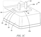
FIGS. 1A-1D illustrate one embodiment of an adapter mechanism. FIG. 1A is a perspective view of the adapter mechanism embodiment with an attachment device embodiment of the adapter mechanism in a retracted position, and FIG. 1B is a perspective view of the adapter mechanism embodiment with the attachment device in an extended position. FIG. 1C is a perspective view of an electrical adapter of the adapter mechanism embodiment. FIG. 1D is a perspective view of the attachment device embodiment.
FIGS. 2A-2D illustrate another embodiment of an adapter mechanism. FIG. 2A is a perspective view of the adapter mechanism embodiment with an attachment device embodiment of the adapter mechanism in a retracted position, and FIG. 2B is a perspective view of the adapter mechanism embodiment with the attachment device in an extended position. FIG. 2C is a perspective view of an electrical adapter of the adapter mechanism embodiment. FIG. 2D is a perspective view of the attachment device embodiment.
FIGS. 3A-3B illustrate a further embodiment of an adapter mechanism. FIG. 3A is a perspective view of the adapter mechanism embodiment with an attachment device embodiment of the adapter mechanism in an extended position, and FIG. 3B is a perspective view of the adapter mechanism embodiment with the attachment device being moved to a retracted position.
FIG. 4 is a flow diagram of a method of installing an adapter mechanism at an electrical outlet.
DETAILED DESCRIPTION
The following detailed description is exemplary in nature and is not intended to limit the scope, applicability, or configuration of the invention in any way. Rather, the following description provides some practical illustrations for implementing examples of the present invention. Those skilled in the art will recognize that many of the noted examples have a variety of suitable alternatives.
FIGS. 1A-1D show one embodiment of an adapter mechanism 100. The adapter mechanism 100 can include an electrical adapter 105 and an attachment device 110. As shown in FIGS. 1A and 1B, and as will be described further below, the attachment device 110 can be configured to move between a retracted position, an example of which is shown in FIG. 1A, and an extended position, an example of which is shown in FIG. 1B.
FIG. 1C illustrates a perspective view of the electrical adapter 105 in isolation. The electrical adapter 105 can include an adapter housing 115 and a pair of conductive prongs 120. The pair of conductive prongs 120 can be configured to be inserted into an electrical outlet so as to receive power from a power source accessible via the electrical outlet. The adapter housing 115 can include one or more components thereat configured to convert one or more attributes of the power source to those of an electrical device electrically connected to the electrical adapter 105. For example, one or more components at the adapter housing 115 can be configured to modify power or signal attributes of the power source to be compatible with the power consumption characteristics of the electrical device electrically connected to the electrical adapter 105. The adapter housing 115 can further include an electrical coupling (e.g., spaced apart from the pair of conductive prongs 120) for electrically connecting to the electrical device. Thus, the electrical adapter 105 can receive power from the power source via the pair of conductive prongs 120, modify one or more characteristics of the power received from the power source, and supply the modified power to an electrical device electrically coupled to the electrical adapter 105.
The adapter housing 115 can include one or more complementary connectors configured to couple to the attachment device 110. As shown in the illustrated embodiment, the adapter housing 115 can include a first complementary connector 125. The first complementary connector 125 can be configured to couple to the attachment device 110, for instance, when the attachment device 110 is in a particular position relative to the adapter housing 115. In the illustrated embodiment, the first complementary connector 125 is configured to couple to the attachment device 110 when the attachment device 110 is in an extended position so as to thereby secure the attachment device 110 in place at the adapter housing 115 when the attachment device 110 is in the extended position. In the illustrated embodiment, the first complementary connector 125 includes a first receptacle 125 a and a second receptacle 125 b that is spaced apart from the first receptacle 125 a. Each of the first and second receptacles 125 a, 125 b can be defined by the adapter housing 115 (e.g., adjacent the pair of conductive prongs 120). In the illustrated embodiment, each of the first and second receptacles 125 a, 125 b is defined as a slot at the adapter housing 115. The slot defined by each of the of the first and second receptacles 125 a, 125 b is open at one end portion 126 of each of the first and second receptacles 125 a, 125 b and closed at a second, opposite end portion 127 of each of the first and second receptacles 125 a, 125 b.
The adapter housing 115 in the illustrated embodiment also includes a third complementary connector 130. The third complementary connector 130 can also be configured to couple to the attachment device 110, for instance when the attachment device 110 is in a particular position relative to the adapter housing 115. In the illustrated embodiment, the third complementary connector 130 is configured to couple to the attachment device 110 when the attachment device 110 is in a retracted position so as to thereby secure the attachment device 110 in place at the adapter housing 115 when the attachment device 110 is in the retracted position. In the illustrated embodiment, the third complementary connector 130 includes a third receptacle 130 a that can be defined by the adapter housing 115 (e.g., adjacent the pair of conductive prongs 120). In the illustrated embodiment, the third receptacle 130 a is defined as a slot at the adapter housing 115, and the third receptacle 130 a is offset from each of the first and second receptacles 125 a, 125 b. In particular, as shown here, the third receptacle 130 a is open at a side of the pair of conductive prongs 120 opposite the one end portion 126 of each of the first and second receptacles 125 a, 125 b.
FIG. 1D illustrates a perspective view of the attachment device 110 in isolation. The attachment device 110 can include a fixation aperture 135. The fixation aperture 135 can be configured to receive a fixation element to fix the electrical adapter 105 to a wall adjacent an electrical outlet (e.g., into which the pair of electrical prongs 120 are configured to be inserted). Accordingly, the fixation aperture 135 can be sized so as to receive the fixation element, such as a screw, bolt, nail, other appropriate fixation element, therethrough. In some examples, depending on the type of fixation element that is to be used with the fixation aperture 135, the fixation aperture 135 can define threading for coupling to the inserted fixation element.
The attachment device 110 can also include a second complementary connector 140 and a prong opening 150. The prong opening 150 can extend through the attachment device 110. The prong opening 150 can be configured to receive the pair of conductive prongs 120 so that the pair of conductive prongs 120 extend through the attachment device 100 at the prong opening 150. The fixation aperture 135 and the second complementary connector 140 can be spaced apart on the attachment device 110 by the prong opening 150.
The attachment device 110 can include one or more complementary connectors configured to couple to the adapter housing 115. This can include the second complementary connector 140. As shown in the illustrated embodiment, the second complementary connector 140 can be configured to couple to the adapter housing 115, for instance, when the attachment device 110 is in a particular position relative to the adapter housing 115. In the illustrated embodiment, the second complementary connector 140 is configured to couple to the adapter housing 115 when the attachment device 110 is in the extended position so as to thereby secure the attachment device 110 in place at the adapter housing 115 when the attachment device 110 is in the extended position. In the illustrated embodiment, the second complementary connector 140 includes a first projection 140 a and a second projection 140 b that is spaced from the first projection 140 a. The first projection 140 a can be configured to couple to the first receptacle 125 a when the attachment device 110 is in the extended position, and the second projection 140 b can be configured to couple to the second receptable 125 b when the attachment device 110 is in the extended position. As shown in the illustrated example, each of the first and second projections 140 a, 140 b is defined at, and extends from, a first end portion 151 of the prong opening 150 opposite a second end portion 152 of the prong opening 150 adjacent the fixation aperture 135.
The attachment device 110 in the illustrated embodiment also includes a fourth complementary connector 145. The fourth complementary connector 145 can also be configured to couple to the adapter housing 115, for instance, when the attachment device 110 is in a particular position relative to the adapter housing 115. In the illustrated embodiment, the fourth complementary connector 145 is configured to couple to the adapter housing 115 when the attachment device 110 is in the retracted position so as to thereby secure the attachment device 110 in place at the adapter housing 115 when the attachment device 110 is in the retracted position. In the illustrated embodiment, the fourth complementary connector 145 includes a third projection 145 a. The third projection 145 a can be configured to couple to the third receptacle 130 a when the attachment device 110 is in the retracted position. As shown in the illustrated example, the third projection 145 a is defined at, and extends from, the second end portion 152 of the prong opening 150 adjacent the fixation aperture 135.
FIGS. 1A and 1B illustrate the attachment device 110 in retracted and extended positions. Specifically, FIG. 1A is a perspective view of the adapter mechanism 100 with the attachment device 110 in an exemplary retracted position, and FIG. 1B is a perspective view of the adapter mechanism 100 with the attachment device 110 in an exemplary extended position. The attachment device 110 can be configured to move, relative to the adapter housing 115, between a retracted position, such as that shown in FIG. 1A, and an extended position, such as that shown in FIG. 1B.
When the attachment device 110 is in the retracted position, such as that shown in FIG. 1A, the second complementary connector 140 can be uncoupled from the first complementary connector 125. But, in this embodiment, to secure the attachment device 110, relative to the adapter housing 115, at the retracted position, the fourth complementary connector 140 can be coupled to the third complementary connector 130. Also, when the attachment device 110 is in the retracted position, such as that shown in FIG. 1A, the fixation aperture 135 can interface with the adapter housing 115. For instance, as shown in the illustrated example, when the attachment device 110 is in the retracted position, the adapter housing 115 can block the fixation aperture 135 from receiving a fixation element through the fixation aperture 135. In some such cases, an end on the fixation aperture 135, interfacing with the adapter housing 115, can contact the adapter housing 115. When the attachment device 110 is in the retracted position, the adapter mechanism 100 can be relatively more compact than when the attachment device 110 is in the extended position.
When the attachment device 110 is in the extended position, such as that shown in FIG. 1B, the fixation aperture 135 can be extended out from the adapter housing 115 and the second complementary connector 140 can be coupled to the first complementary connector 125 to secure the attachment device 110 in place at the adapter housing 115. Likewise, in this embodiment, when the attachment device 110 is in the extended position, the fourth complementary connector 140 can be uncoupled from the third complementary connector 130. When the attachment device 110 is in the extended position, the adapter mechanism 100 can be relatively less compact than when the attachment device 110 is in the extended position. In particular, as shown in FIG. 1B, the attachment device 110 can extend out from the adapter housing 115 an extension distance 155. The extension distance 155 can be greater when the attachment device 110 is in the extended position than when the attachment device 110 is in the retracted position, thus rendering the adapter mechanism 100 relatively more compact when in the retracted position than when in the extended position.
As noted, the attachment device 110 configured to move, relative to the adapter housing 115, between the retracted and extended positions. In in the illustrated embodiment of the adapter mechanism 100, the attachment device 110 is configured to slide along, and relative to, the adapter housing 115 from the retracted position to the extended position. By moving the attachment device 110 from the retracted position to the extended position, the fixation aperture 135 can be positioned so as to receive a fixation element through the fixation aperture. As such, the adapter mechanism 100 can be selectively placed into an installation configuration (e.g., the extended position of the attachment device) in which a fixation element is needed to fix the electrical adapter 105 to a wall adjacent the electrical outlet at which the pair of conductive prongs 120. And, the adapter mechanism 100 can be selectively placed into a relatively more compact installation configuration (e.g., the retracted position of the attachment device 110) when a fixation element is not needed to fix the electrical adapter 105 to a wall.
FIGS. 2A-2D show another embodiment of an adapter mechanism 200. The adapter mechanism 200 can be similar to the adapter mechanism 100 described previously herein and like reference characters are used to denote like elements. The adapter mechanism 200 can include the electrical adapter 105 and the attachment device 110. And, as shown in FIGS. 2A and 2B, and as will be described further below, the attachment device 110 can be configured to move between the retracted position, an example of which is shown in FIG. 2A, and the extended position, an example of which is shown in FIG. 2B.
FIG. 2C illustrates a perspective view of the electrical adapter 105 in isolation. The electrical adapter 105 can include the adapter housing 115 and the pair of conductive prongs 120, such as described previously. The adapter housing 115 can include one or more complementary connectors configured to couple to the attachment device 110. As shown in the illustrated embodiment, the adapter housing 115 can include a first complementary connector 225. The first complementary connector 225 can be configured to couple to the attachment device 110, for instance, when the attachment device 110 is in a particular position relative to the adapter housing 115. In the illustrated embodiment, the first complementary connector 225 is configured to couple to the attachment device 110 when the attachment device 110 is in an extended position so as to thereby secure the attachment device 110 in place at the adapter housing 115 when the attachment device 110 is in the extended position. In the illustrated embodiment, the first complementary connector 225 includes a first receptacle 225 a, a second receptacle 225 b that is spaced apart from the first receptacle 225 a, and a third receptacle 225 c that is spaced apart from each of the first receptacle 225 a and the second receptacle 225 c. Each of the first, second, and third receptacles 225 a, 225 b, 225 c can be defined by the adapter housing 115 (e.g., adjacent the pair of conductive prongs 120). In the illustrated embodiment, each of the first, second, and third receptacles 225 a, 225 b, 225 c is defined as a slot at the adapter housing 115. The slot defined by each of the of the first, second, and third receptacles 225 a, 225 b, 225 c is open at one end portion 226 of each of the first, second, and third receptacles 225 a, 225 b, 225 c and closed at a second, opposite end portion 227 of each of the first, second, and third receptacles 225 a, 225 b, 225 c. The illustrated embodiment of the adapter housing 115 may not include the third complementary connector 130 as is present in the embodiment illustrated in FIGS. 1A-1D.
FIG. 2D illustrates a perspective view of the attachment device 110 in isolation. The attachment device 110 can include the fixation aperture 135, a second complementary connector 240, and the prong opening 150. The second complementary connector 240 can be configured to couple to the adapter housing 115, for instance, when the attachment device 110 is in a particular position relative to the adapter housing 115. In the illustrated embodiment, the second complementary connector 240 is configured to couple to the adapter housing 115 when the attachment device 110 is in the extended position so as to thereby secure the attachment device 110 in place at the adapter housing 115 when the attachment device 110 is in the extended position. In the illustrated embodiment, the second complementary connector 240 includes a first projection 240 a, a second projection 240 b that is spaced from the first projection 240 a, and a third projection 240 c that is spaced from each of the first and second projections 240 a, 240 b. When the attachment device 110 is in the extended position, the first projection 240 a can be configured to couple to the first receptacle 225 a, the second projection 240 b can be configured to couple to the second receptable 225 b, and the third projection 240 c can be configured to couple to the third receptacle 225 c. As shown in the illustrated example, each of the first, second, and third projections 240 a, 240 b, 240 c is defined at, and extends from, the first end portion 151 of the prong opening 150 opposite the second end portion 152 of the prong opening 150 adjacent the fixation aperture 135. The illustrated embodiment of the adapter housing 115 may not include the fourth complementary connector 145 as is present in the embodiment illustrated in FIGS. 1A-1D.
FIGS. 2A and 2B illustrate the attachment device 110 in retracted and extended positions. Specifically, FIG. 2A is a perspective view of the adapter mechanism 200 with the attachment device 110 in an exemplary retracted position, and FIG. 2B is a perspective view of the adapter mechanism 200 with the attachment device 110 in an exemplary extended position. The attachment device 110 can be configured to move, relative to the adapter housing 115, between a retracted position, such as that shown in FIG. 2A, and an extended position, such as that shown in FIG. 2B.
When the attachment device 110 is in the retracted position, such as that shown in FIG. 2A, the second complementary connector 240 can be uncoupled from the first complementary connector 225. Also, when the attachment device 110 is in the retracted position, such as that shown in FIG. 2A, the fixation aperture 135 can interface with the adapter housing 115 as described previously with respect to the embodiment of the adapter mechanism 100 of FIGS. 1A-1D. When the attachment device 110 is in the retracted position, the adapter mechanism 200 can be relatively more compact than when the attachment device 110 is in the extended position.
When the attachment device 110 is in the extended position, such as that shown in FIG. 2B, the fixation aperture 135 can be extended out from the adapter housing 115 and the second complementary connector 240 can be coupled to the first complementary connector 225 to secure the attachment device 110 in place at the adapter housing 115. When the attachment device 110 is in the extended position, the adapter mechanism 200 can be relatively less compact than when the attachment device 110 is in the extended position. In particular, as shown in FIG. 2B, the attachment device 110 can extend out from the adapter housing 115 the extension distance 155 as described previously.
As noted, the attachment device 110 configured to move, relative to the adapter housing 115, between the retracted and extended positions. In in the illustrated embodiment of the adapter mechanism 200, the attachment device 110 is configured to slide along, and relative to, the adapter housing 115 from the retracted position to the extended position. By moving the attachment device 110 from the retracted position to the extended position, the fixation aperture 135 can be positioned so as to receive a fixation element 136 through the fixation aperture 135. As such, the adapter mechanism 200 can be selectively placed into an installation configuration (e.g., the extended position of the attachment device) in which the fixation element 136 is needed to fix the electrical adapter 105 to a wall adjacent the electrical outlet at which the pair of conductive prongs 120. And, the adapter mechanism 200 can be selectively placed into a relatively more compact installation configuration (e.g., the retracted position of the attachment device 110) when the fixation element 136 is not needed to fix the electrical adapter 105 to a wall.
FIGS. 3A and 3B illustrate yet another embodiment of an adapter mechanism 300. The adapter mechanism 300 can be similar to the adapter mechanisms 100 and 200 described previously herein and like reference characters are used to denote like elements. The adapter mechanism 300 can include the electrical adapter 105 and the attachment device 110. And, as shown in FIGS. 3A and 3B, and as will be described further below, the attachment device 110 can be configured to move between the retracted position and the extended position. Specifically, FIG. 3A is a perspective view of the adapter mechanism 300 with the attachment device 110 in an extended position, and FIG. 3B is a perspective view of the adapter mechanism 300 with the attachment device 110 being moved toward a retracted position.
As shown in the illustrated embodiment, the adapter housing 115 can include a first complementary connector 325. The first complementary connector 325 can be configured to couple to the attachment device 110, for instance, when the attachment device 110 is in an extended position so as to thereby secure the attachment device 110 in place at the adapter housing 115. In the illustrated embodiment, the first complementary connector 325 includes a first perforated connector. The first perforated connector can extend along the contacting interface between the attachment device 110 and the adapter housing 115. The first perforated connector can be defined by the adapter housing 115 and/or be a removable connected component at the adapter housing 115.
As also shown in the illustrated embodiment, the attachment device 110 can include the fixation aperture 135 and a second complementary connector 340. The second complementary connector 340 can be configured to couple to the adapter housing 115, for instance, when the attachment device 110 is in the extended position so as to thereby secure the attachment device 110 in place at the adapter housing 115. In the illustrated embodiment, the second complementary connector 340 includes a second perforated connector that is complementary to the first perforated connector of the first complementary connector 325. When the attachment device 110 is in the extended position, such as that shown in FIG. 3A, the second complementary connector 340 can be configured to couple to the first complementary connector 325 such that the first perforated connector and the second perforated connector form a perforated connection between the attachment device 110 and the adapter housing 115.
FIG. 3B illustrates the attachment device 110 being moved to the retracted position. The attachment device 110 can be configured to move, relative to the adapter housing 115, from the extended position, such as that shown in FIG. 3A, to a retracted position. A retracted position for the adapter mechanism 300 can be defined, for example, as an angle formed between the first complementary connector 325 and the second complementary connector 340 that is other than ninety degrees. As shown in FIG. 3B, the attachment device 110 has been moved relative to the adapter housing 115 to be at an angle between zero and ninety degrees relative to a plane extending along the surface of the adapter housing 115 at which the first and second complementary connectors 325, 340 are coupled.
In some cases, the retracted position of the attachment device 110 can include removal of the attachment device 110 from the adapter housing 115. For example, the perforated connection formed by the first perforated connector, of the first complementary connector 325, and the second perforated connector, of the second complementary connector 340 can be configured to allow the attachment device 110 to be selectively removed from the adapter housing 115 at the interface of the first and second complementary connectors 325, 340. Thus, moving the attachment device 110 to the retracted position can include rotating the attachment device 110 relative to the adapter housing 115 via the perforated connection therebetween so as to uncouple the second complementary connector 340 from the first complementary connector 325 and remove the attachment device 110 from the adapter housing 115. Thus, when the attachment device 110 is in the extended position, the fixation aperture 135 can be extended out from the adapter housing 115 and the second complementary connector 340 can be coupled to the first complementary connector 325 to secure the attachment device 110 in place at the adapter housing 115. And, when the attachment device 110 is in the retracted position, the second complementary connector 340 can be rotated relative to the first complementary connector 25 and/or uncoupled from the first complementary connector 325 via the interface between the first and second complementary connectors 325, 340.
FIG. 4 is a flow diagram of a method 400 of installing an adapter mechanism at an electrical outlet. The adapter mechanism can include an electrical adapter, such as the electrical adapter illustrated and/or described elsewhere herein, and an attachment device, such as the attachment device illustrated and/or described elsewhere herein. And, other features described with respect to the method 400 can be the same as, or similar to, the corresponding features illustrated and/or described elsewhere herein
At step 410, the method 400 includes moving the attachment device, relative to an adapter housing of the electrical adapter, from a retracted position to an extended position. In some embodiments, moving the attachment device, relative to an adapter housing of the electrical adapter, from the retracted position to the extended position includes sliding the attachment device along the adapter housing from the retracted position to the extended position. In some embodiments, moving the attachment device, relative to an adapter housing of the electrical adapter, from the retracted position to the extended position includes rotating the attachment device relative to the adapter housing from the extended position to the retracted position.
When the attachment device is in the retracted position, a second complementary connector of the attachment device can be uncoupled from a first complementary connector of the adapter housing. For example, in some embodiments, wherein when the attachment device is in the retracted position the fixation aperture can interface with the adapter housing. And, when the attachment device is in the extended position, a fixation aperture of the attachment device can be extended out from the adapter housing and the second complementary connector can be coupled to the first complementary connector to secure the attachment device in place at the adapter housing. For example, in some embodiments when the attachment device is in the extended position, the electrical adapter can be fixed to the wall adjacent the electrical outlet by a fixation element placed through the fixation aperture.
At step 420, the method 400 includes plugging a pair of conductive prongs of the electrical adapter into an electrical outlet. For example, in one embodiment, the pair of conductive prongs can be plugged into the electrical outlet when the attachment device is in the extended position. The pair of conductive prongs of the electrical adapter can extend through the attachment device via a prong opening defined at the attachment device. For instance, the pair of conductive prongs of the electrical adapter can extend through the attachment device via the prong opening when the attachment device is in the retracted position and when the attachment device is in the extended position. In some embodiments, the fixation aperture and the second complementary connector can be spaced apart on the attachment device by the prong opening. Also, in some embodiments, the second complementary connector of the attachment device can be defined at a first end portion of the prong opening opposite a second end portion of the prong opening adjacent the fixation aperture.
At step 430, the method 400 includes fixing the electrical adapter to a wall adjacent the electrical outlet, via at least the fixation aperture, when the attachment device is in the extended position.
Various examples have been described. These and other examples are within the scope of the following claims.

Claims (20)

What is claimed is:
1. An adapter mechanism comprising:
an electrical adapter, the electrical adapter comprising an adapter housing and a pair of conductive prongs, the adapter housing comprising a first complementary connector, and the pair of conductive prongs configured to be inserted into an electrical outlet; and
an attachment device, the attachment device comprising a fixation aperture and a second complementary connector, wherein the attachment device is configured to move relative to the adapter housing between a retracted position and an extended position, wherein when the attachment device is in the retracted position the second complementary connector is uncoupled from the first complementary connector, and wherein when the attachment device is in the extended position the fixation aperture is extended out from the adapter housing and the second complementary connector is coupled to the first complementary connector to secure the attachment device in place at the adapter housing.
2. The adapter mechanism of claim 1, wherein when the attachment device is in the retracted position the fixation aperture interfaces with the adapter housing.
3. The adapter mechanism of claim 2, wherein when the attachment device is in the retracted position the adapter housing blocks the fixation aperture from receiving a fixation element through the fixation aperture.
4. The adapter mechanism of claim 1, wherein the attachment device further comprises a prong opening extending through the attachment device.
5. The adapter mechanism of claim 4, wherein the prong opening is configured to receive the pair of conductive prongs to extend through the attachment device.
6. The adapter mechanism of claim 4, wherein the fixation aperture and the second complementary connector are spaced apart on the attachment device by the prong opening.
7. The adapter mechanism of claim 1, wherein the fixation aperture is configured to receive a fixation element to fix the electrical adapter to a wall adjacent the electrical outlet.
8. The adapter mechanism of claim 1, wherein the attachment device is configured to slide along the adapter housing from the retracted position to the extended position.
9. The adapter mechanism of claim 1, wherein the first complementary connector comprises a first receptacle, and wherein the second complementary connector comprises a first projection configured to couple to the first receptacle when the attachment device is in the extended position.
10. The adapter mechanism of claim 9, wherein the first complementary connector further comprises a second receptacle spaced apart from the first receptacle, and wherein the second complementary connector further comprises a second projection, spaced from the first projection, configured to be coupled to the second receptacle when the attachment device is in the extended position.
11. The adapter mechanism of claim 9, wherein the attachment device further comprises a prong opening extending through the attachment device, and wherein the first projection is defined at a first end portion of the prong opening opposite a second end portion of the prong opening adjacent the fixation aperture.
12. A method of installing an adapter mechanism at an electrical outlet, the adapter mechanism comprising an electrical adapter and an attachment device, the method comprising the steps of:
moving the attachment device, relative to an adapter housing of the electrical adapter, from a retracted position to an extended position, wherein when the attachment device is in the retracted position a second complementary connector of the attachment device is uncoupled from a first complementary connector of the adapter housing, and wherein when the attachment device is in the extended position a fixation aperture of the attachment device is extended out from the adapter housing and the second complementary connector is coupled to the first complementary connector to secure the attachment device in place at the adapter housing;
plugging a pair of conductive prongs of the electrical adapter into an electrical outlet; and
fixing the electrical adapter to a wall adjacent the electrical outlet, via at least the fixation aperture, when the attachment device is in the extended position.
13. The method of claim 12, wherein the pair of conductive prongs is plugged into the electrical outlet when the attachment device is in the extended position.
14. The method of claim 12, wherein when the attachment device is in the retracted position the fixation aperture interfaces with the adapter housing.
15. The method of claim 12, wherein the pair of conductive prongs of the electrical adapter extend through the attachment device via a prong opening defined at the attachment device.
16. The method of claim 15, wherein the pair of conductive prongs of the electrical adapter extend through the attachment device via the prong opening when the attachment device is in the retracted position and when the attachment device is in the extended position.
17. The method of claim 15, wherein the fixation aperture and the second complementary connector are spaced apart on the attachment device by the prong opening.
18. The method of claim 15, wherein the second complementary connector of the attachment device is defined at a first end portion of the prong opening opposite a second end portion of the prong opening adjacent the fixation aperture.
19. The method of claim 12, wherein the electrical adapter is fixed to the wall adjacent the electrical outlet when the attachment device is in the extended position by a fixation element placed through the fixation aperture.
20. The method of claim 12, wherein moving the attachment device, relative to an adapter housing of the electrical adapter, from the retracted position to the extended position comprises sliding the attachment device along the adapter housing from the retracted position to the extended position.
US17/067,883 2020-10-12 2020-10-12 Adapter mechanism Active US11283224B1 (en)

Priority Applications (4)

Application Number Priority Date Filing Date Title
US17/067,883 US11283224B1 (en) 2020-10-12 2020-10-12 Adapter mechanism
CN202180069701.9A CN116349096A (en) 2020-10-12 2021-09-15 Adapter mechanism
PCT/US2021/050478 WO2022081291A1 (en) 2020-10-12 2021-09-15 Adapter mechanism
EP21790701.3A EP4226468A1 (en) 2020-10-12 2021-09-15 Adapter mechanism

Applications Claiming Priority (1)

Application Number Priority Date Filing Date Title
US17/067,883 US11283224B1 (en) 2020-10-12 2020-10-12 Adapter mechanism

Publications (2)

Publication Number Publication Date
US11283224B1 true US11283224B1 (en) 2022-03-22
US20220115825A1 US20220115825A1 (en) 2022-04-14

Family

ID=78087558

Family Applications (1)

Application Number Title Priority Date Filing Date
US17/067,883 Active US11283224B1 (en) 2020-10-12 2020-10-12 Adapter mechanism

Country Status (4)

Country Link
US (1) US11283224B1 (en)
EP (1) EP4226468A1 (en)
CN (1) CN116349096A (en)
WO (1) WO2022081291A1 (en)

Cited By (1)

* Cited by examiner, † Cited by third party
Publication number Priority date Publication date Assignee Title
US11777255B1 (en) * 2023-04-25 2023-10-03 Austin Hughes Electronics Ltd Power distribution unit, power outlet modules with secure socket-and-plug connection

Citations (24)

* Cited by examiner, † Cited by third party
Publication number Priority date Publication date Assignee Title
US5613863A (en) * 1995-05-18 1997-03-25 Motorola, Inc. Power transformer
US5634806A (en) * 1994-02-24 1997-06-03 Asian Micro Sources, Inc. Interchangeable collapsible plug device for battery charger
US5684689A (en) * 1996-06-19 1997-11-04 Advanced Mobile Solutions, Inc. Interchangeable plug power supply with automatically adjusting input voltage receiving mechanism
US5791921A (en) * 1997-01-09 1998-08-11 Lee; Anthony Easily operable universal adapter
US6227888B1 (en) * 1994-02-24 2001-05-08 Advanced Mobile Solutions, Inc. Interchangeable plug device
US6659782B2 (en) * 2002-03-20 2003-12-09 Formosa Electronic Industries Inc. Electrical adapter with dual plug structure
US6669495B2 (en) * 2000-11-06 2003-12-30 Research In Motion Limited Universal adapter with interchangeable plugs
US6923667B1 (en) * 2004-05-17 2005-08-02 Acbel Polytech Inc. Rotary adapter
US6942508B2 (en) * 2003-01-03 2005-09-13 Modern Sense Ltd. Electrical adapter
US7008246B2 (en) * 2004-02-06 2006-03-07 Rui Zhuge Electric plug with replaceable head unit
US7118399B1 (en) * 2005-05-09 2006-10-10 Delta Electronics, Inc. Electronic device with replaceable plug
US7223126B2 (en) * 2003-08-21 2007-05-29 Helms-Man Industrial Co., Ltd. Plug device with a plug adapter
US7300297B1 (en) * 2006-08-25 2007-11-27 Sunfone Electronics Co. Power supply with a changeable plug
US7489952B2 (en) * 2003-03-24 2009-02-10 Research In Motion Limited Battery charging assembly
US7547219B2 (en) * 2005-07-04 2009-06-16 Rui Zhuge Electrical safety adaptor with replaceable head unit
CN201805110U (en) 2010-08-26 2011-04-20 罗娟 Adapter with replaceable connecting and inserting component
US8087946B2 (en) * 2009-08-27 2012-01-03 Tamura Power Technology Co., Ltd. Power adapter having a replaceable plug
US8469730B2 (en) * 2008-03-07 2013-06-25 Belkin International, Inc. Electrical connector and method of manufacturing same
US20140177185A1 (en) * 2012-12-21 2014-06-26 Lastar, Inc. Wall plate assembly with signal-adaptive features
US9543704B1 (en) * 2015-11-05 2017-01-10 Hong Fu Jin Precision Industry (Shenzhen) Co., Ltd. Power adapter
US9985397B2 (en) * 2014-08-25 2018-05-29 Friwo Gerätebau Gmbh Plug-in power supply with interchangeable mains plug units
US20190109408A1 (en) * 2017-10-05 2019-04-11 Fci Usa Llc Ruggedized connector system
US10601194B1 (en) 2018-09-28 2020-03-24 Min-Hung Chien Electrical power adapter
US20210210915A1 (en) * 2020-01-07 2021-07-08 Toka, Llc Wall mounting outlet extender

Family Cites Families (4)

* Cited by examiner, † Cited by third party
Publication number Priority date Publication date Assignee Title
US4846706A (en) * 1988-04-05 1989-07-11 Hop Lee Electric plug
US7798838B2 (en) * 2007-08-28 2010-09-21 Grieff Enterprises, Inc. Electrical plug adapter
US7874864B2 (en) * 2009-01-23 2011-01-25 Vince Luu Cable plug with folding retention member
US11005214B2 (en) * 2018-11-09 2021-05-11 William Edwards Locking electrical adaptor

Patent Citations (25)

* Cited by examiner, † Cited by third party
Publication number Priority date Publication date Assignee Title
US5634806A (en) * 1994-02-24 1997-06-03 Asian Micro Sources, Inc. Interchangeable collapsible plug device for battery charger
US6227888B1 (en) * 1994-02-24 2001-05-08 Advanced Mobile Solutions, Inc. Interchangeable plug device
US5613863A (en) * 1995-05-18 1997-03-25 Motorola, Inc. Power transformer
US5684689A (en) * 1996-06-19 1997-11-04 Advanced Mobile Solutions, Inc. Interchangeable plug power supply with automatically adjusting input voltage receiving mechanism
US5973948A (en) * 1996-06-19 1999-10-26 Advanced Mobile Solutions, Inc. Universal linear power supply
US5791921A (en) * 1997-01-09 1998-08-11 Lee; Anthony Easily operable universal adapter
US6669495B2 (en) * 2000-11-06 2003-12-30 Research In Motion Limited Universal adapter with interchangeable plugs
US6659782B2 (en) * 2002-03-20 2003-12-09 Formosa Electronic Industries Inc. Electrical adapter with dual plug structure
US6942508B2 (en) * 2003-01-03 2005-09-13 Modern Sense Ltd. Electrical adapter
US7489952B2 (en) * 2003-03-24 2009-02-10 Research In Motion Limited Battery charging assembly
US7223126B2 (en) * 2003-08-21 2007-05-29 Helms-Man Industrial Co., Ltd. Plug device with a plug adapter
US7008246B2 (en) * 2004-02-06 2006-03-07 Rui Zhuge Electric plug with replaceable head unit
US6923667B1 (en) * 2004-05-17 2005-08-02 Acbel Polytech Inc. Rotary adapter
US7118399B1 (en) * 2005-05-09 2006-10-10 Delta Electronics, Inc. Electronic device with replaceable plug
US7547219B2 (en) * 2005-07-04 2009-06-16 Rui Zhuge Electrical safety adaptor with replaceable head unit
US7300297B1 (en) * 2006-08-25 2007-11-27 Sunfone Electronics Co. Power supply with a changeable plug
US8469730B2 (en) * 2008-03-07 2013-06-25 Belkin International, Inc. Electrical connector and method of manufacturing same
US8087946B2 (en) * 2009-08-27 2012-01-03 Tamura Power Technology Co., Ltd. Power adapter having a replaceable plug
CN201805110U (en) 2010-08-26 2011-04-20 罗娟 Adapter with replaceable connecting and inserting component
US20140177185A1 (en) * 2012-12-21 2014-06-26 Lastar, Inc. Wall plate assembly with signal-adaptive features
US9985397B2 (en) * 2014-08-25 2018-05-29 Friwo Gerätebau Gmbh Plug-in power supply with interchangeable mains plug units
US9543704B1 (en) * 2015-11-05 2017-01-10 Hong Fu Jin Precision Industry (Shenzhen) Co., Ltd. Power adapter
US20190109408A1 (en) * 2017-10-05 2019-04-11 Fci Usa Llc Ruggedized connector system
US10601194B1 (en) 2018-09-28 2020-03-24 Min-Hung Chien Electrical power adapter
US20210210915A1 (en) * 2020-01-07 2021-07-08 Toka, Llc Wall mounting outlet extender

Non-Patent Citations (1)

* Cited by examiner, † Cited by third party
Title
English Abstract and Machine Translation for Chinese Publication No. CN201805110U, published Apr. 20, 2011, 10 pgs.

Cited By (1)

* Cited by examiner, † Cited by third party
Publication number Priority date Publication date Assignee Title
US11777255B1 (en) * 2023-04-25 2023-10-03 Austin Hughes Electronics Ltd Power distribution unit, power outlet modules with secure socket-and-plug connection

Also Published As

Publication number Publication date
US20220115825A1 (en) 2022-04-14
CN116349096A (en) 2023-06-27
EP4226468A1 (en) 2023-08-16
WO2022081291A1 (en) 2022-04-21

Similar Documents

Publication Publication Date Title
US11728604B2 (en) Combination outlet and power distribution unit incorporating the same
AU2007306960B2 (en) XLR cable connector
US7534148B2 (en) Power terminal block
US20080108242A1 (en) High frequency self-lock connector
US6099330A (en) Connector with lever
US11600947B2 (en) Electrical connector
CN201247879Y (en) Plate-to-plate concentration mounting type RF coaxial connector
WO2012041746A1 (en) Contact housing for electrical contact units, electrical plug connector or mating connector as well as an assembled electrical conductor
US7731519B1 (en) Adaptable universal electrical connector system particularly adapted for use in repair or replacement of electrical components such as relays, solenoids and the like
TWM551358U (en) Connector
US20210083415A1 (en) Coaxial connector with axially-floating inner contact
US11038311B2 (en) Multi-functional charger
US8137138B2 (en) Housing base for an electrical connector
US11283224B1 (en) Adapter mechanism
US6805575B2 (en) Guide system for contact plugs
RU2444822C2 (en) Device for connecting two male connectors, having compact and simple design
CN113196573A (en) Adapter housing for a contact insert for fastening to a mounting rail
US10222562B1 (en) Flexible connector interface
KR20220000457U (en) High frequency connector with an automatic lock structure
US20110014810A1 (en) Connector frame
CN103858280A (en) Structure for connecting wiring conductor
US20070020984A1 (en) Alignment system
CN216355094U (en) Plug connector and connector device
US10588234B2 (en) Semiconductor assembly
CN220122229U (en) Connector capable of being connected on two sides

Legal Events

Date Code Title Description
FEPP Fee payment procedure

Free format text: ENTITY STATUS SET TO UNDISCOUNTED (ORIGINAL EVENT CODE: BIG.); ENTITY STATUS OF PATENT OWNER: LARGE ENTITY

AS Assignment

Owner name: ADEMCO INC., MINNESOTA

Free format text: ASSIGNMENT OF ASSIGNORS INTEREST;ASSIGNORS:WANG, YAO;CHEN, YONGJUN;SHI, BIN;REEL/FRAME:054922/0197

Effective date: 20201009

STCF Information on status: patent grant

Free format text: PATENTED CASE