US11280967B2 - Method for making a low-loss fiber optic connector - Google Patents
Method for making a low-loss fiber optic connector Download PDFInfo
- Publication number
- US11280967B2 US11280967B2 US17/175,475 US202117175475A US11280967B2 US 11280967 B2 US11280967 B2 US 11280967B2 US 202117175475 A US202117175475 A US 202117175475A US 11280967 B2 US11280967 B2 US 11280967B2
- Authority
- US
- United States
- Prior art keywords
- ferrule
- optical fiber
- population
- bore
- ferrules
- Prior art date
- Legal status (The legal status is an assumption and is not a legal conclusion. Google has not performed a legal analysis and makes no representation as to the accuracy of the status listed.)
- Active
Links
Images


Classifications
-
- G—PHYSICS
- G02—OPTICS
- G02B—OPTICAL ELEMENTS, SYSTEMS OR APPARATUS
- G02B6/00—Light guides; Structural details of arrangements comprising light guides and other optical elements, e.g. couplings
- G02B6/24—Coupling light guides
- G02B6/36—Mechanical coupling means
- G02B6/38—Mechanical coupling means having fibre to fibre mating means
- G02B6/3807—Dismountable connectors, i.e. comprising plugs
- G02B6/3833—Details of mounting fibres in ferrules; Assembly methods; Manufacture
- G02B6/3834—Means for centering or aligning the light guide within the ferrule
- G02B6/3843—Means for centering or aligning the light guide within the ferrule with auxiliary facilities for movably aligning or adjusting the fibre within its ferrule, e.g. measuring position or eccentricity
-
- G—PHYSICS
- G02—OPTICS
- G02B—OPTICAL ELEMENTS, SYSTEMS OR APPARATUS
- G02B6/00—Light guides; Structural details of arrangements comprising light guides and other optical elements, e.g. couplings
- G02B6/24—Coupling light guides
- G02B6/36—Mechanical coupling means
- G02B6/38—Mechanical coupling means having fibre to fibre mating means
- G02B6/3807—Dismountable connectors, i.e. comprising plugs
- G02B6/3869—Mounting ferrules to connector body, i.e. plugs
- G02B6/3871—Ferrule rotatable with respect to plug body, e.g. for setting rotational position ; Fixation of ferrules after rotation
-
- G—PHYSICS
- G02—OPTICS
- G02B—OPTICAL ELEMENTS, SYSTEMS OR APPARATUS
- G02B6/00—Light guides; Structural details of arrangements comprising light guides and other optical elements, e.g. couplings
- G02B6/24—Coupling light guides
- G02B6/36—Mechanical coupling means
- G02B6/38—Mechanical coupling means having fibre to fibre mating means
- G02B6/3807—Dismountable connectors, i.e. comprising plugs
- G02B6/3873—Connectors using guide surfaces for aligning ferrule ends, e.g. tubes, sleeves, V-grooves, rods, pins, balls
- G02B6/3885—Multicore or multichannel optical connectors, i.e. one single ferrule containing more than one fibre, e.g. ribbon type
-
- G—PHYSICS
- G02—OPTICS
- G02B—OPTICAL ELEMENTS, SYSTEMS OR APPARATUS
- G02B6/00—Light guides; Structural details of arrangements comprising light guides and other optical elements, e.g. couplings
- G02B6/24—Coupling light guides
- G02B6/36—Mechanical coupling means
- G02B6/38—Mechanical coupling means having fibre to fibre mating means
- G02B6/3807—Dismountable connectors, i.e. comprising plugs
- G02B6/3887—Anchoring optical cables to connector housings, e.g. strain relief features
- G02B6/3889—Anchoring optical cables to connector housings, e.g. strain relief features using encapsulation for protection, e.g. adhesive, molding or casting resin
-
- G—PHYSICS
- G02—OPTICS
- G02B—OPTICAL ELEMENTS, SYSTEMS OR APPARATUS
- G02B6/00—Light guides; Structural details of arrangements comprising light guides and other optical elements, e.g. couplings
- G02B6/24—Coupling light guides
- G02B6/36—Mechanical coupling means
- G02B6/38—Mechanical coupling means having fibre to fibre mating means
- G02B6/3807—Dismountable connectors, i.e. comprising plugs
- G02B6/389—Dismountable connectors, i.e. comprising plugs characterised by the method of fastening connecting plugs and sockets, e.g. screw- or nut-lock, snap-in, bayonet type
- G02B6/3893—Push-pull type, e.g. snap-in, push-on
-
- G—PHYSICS
- G02—OPTICS
- G02B—OPTICAL ELEMENTS, SYSTEMS OR APPARATUS
- G02B6/00—Light guides; Structural details of arrangements comprising light guides and other optical elements, e.g. couplings
- G02B6/24—Coupling light guides
- G02B6/36—Mechanical coupling means
- G02B6/38—Mechanical coupling means having fibre to fibre mating means
- G02B6/3807—Dismountable connectors, i.e. comprising plugs
- G02B6/3833—Details of mounting fibres in ferrules; Assembly methods; Manufacture
- G02B6/3855—Details of mounting fibres in ferrules; Assembly methods; Manufacture characterised by the method of anchoring or fixing the fibre within the ferrule
- G02B6/3861—Adhesive bonding
Definitions
- This disclosure relates generally to optical connectivity, and more particularly, to a method for making a low-loss fiber optic connector wherein the insertion loss between mated fiber optic connectors at an optical connection is reduced by minimizing the core-to-ferrule offset of each connector.
- Optical fibers are useful in a wide variety of applications, including the telecommunications industry for voice, video, and data transmissions. Benefits of optical fiber include extremely wide bandwidth and low noise operation.
- a telecommunications system that uses optical fibers there are typically many locations where fiber optic cables carrying the optical fibers connect to equipment or other fiber optic cables.
- fiber optic connectors are often provided on the ends of fiber optic cables to non-permanently connect and disconnect optical elements in the fiber optic network.
- the introduction of fiber optic connectors may introduce insertion losses across an optical connection, i.e., at a junction between two or more optical fibers.
- One common optical connection in a network is that between two mated optical connectors, such as within an adapter.
- optical connection may encompass other types of junctions between optical fibers.
- the insertion losses in coupling two optical fibers across an optical connection are generally a function of the alignment of the optical fiber ends, the width of the gap between the ends, and the optical surface condition at the ends.
- the present disclosure primarily focuses on the first of these factors, i.e., reducing misalignments of the optical fibers across the optical connection.
- FIGS. 1 and 2 illustrate an exemplary fiber optic connector 10 used in many modern fiber optic networks.
- the fiber optic connector 10 is shown in the form of a SC-type connector, the features may be applicable to different connector designs. This includes ST, LC, and MU-type connectors, for example, and other single-fiber or multi-fiber connector designs.
- the connector 10 includes a ferrule 12 having a ferrule bore 14 (“micro-bore”) configured to support an optical fiber 16 , a ferrule holder 18 from which the ferrule 12 extends, a housing 20 having a cavity 22 in which the ferrule 12 and ferrule holder 18 are received, and a connector body 24 configured to cooperate with the housing 20 to retain the ferrule 12 and ferrule holder 18 within the housing 20 . More specifically, a back end of the ferrule 12 is received in a first portion of the ferrule holder 18 and is secured therein in a known manner (e.g., press-fit, adhesive, molding the ferrule holder 18 over the back end of the ferrule 12 , etc.).
- a known manner e.g., press-fit, adhesive, molding the ferrule holder 18 over the back end of the ferrule 12 , etc.
- the ferrule 12 and ferrule holder 18 may even be a monolithic structure in some embodiments.
- the ferrule holder 18 is biased to a forward position within the housing 20 by a spring 26 , which extends over a second portion of the ferrule holder 18 that has a reduced cross-sectional diameter/width compared to the first portion.
- the spring 26 also interacts with internal geometry of the connector body 24 , which may be secured to the housing 20 using a snap-fit or the like.
- FIGS. 1 and 2 illustrate a rear portion of the housing 20 having cut-outs or slots on opposite sides so as to define a split shroud.
- the connector body 24 has tabs configured to be snapped into the slots and retained therein due to the geometries of the components.
- a front end of the ferrule 12 projects beyond a front end of the housing 20 .
- the ferrule end face presents the optical fiber 16 for optical coupling with a mating component (e.g., another fiber optic connector; not shown), such as an adapter.
- a mating component e.g., another fiber optic connector; not shown
- the optical fiber(s) in the ferrule can be held in alignment with the optical fiber(s) of the mating ferrule to establish an optical connection.
- light exiting each optical fiber of a first fiber optic connector (of a first fiber optic cable) is introduced into a corresponding optical fiber within an adjacent, second fiber optic connector (of a second fiber optic cable).
- Bare optical fibers typically include an inner core through which the light is configured to travel, and an outer cladding configured to reflect the light back within the core and thereby minimize losses as the light is transmitted through the optical fiber. If contamination such as one or more pieces of debris is present on the end face of the ferrule of either of the fiber optic connectors that terminate the optical fibers, then transmission of optical signals from the inner core of the first optical fiber to the inner core of the second optical fiber optic may be inhibited. Furthermore, if optical fiber cores at an interconnection between first and second optical fibers are misaligned, then transmission of an optical signal from the inner core of the first optical fiber to the inner core of the second optical fiber may be inhibited, resulting in signal degradation at the interconnection. The inner cores must therefore be closely aligned to ensure long life and to minimize transmission loss and optical return loss at optical connection points.
- a method of terminating an optical fiber having an inner core with a fiber optic connector including a ferrule having a micro-bore and an end face with a mating location includes determining a bore bearing angle of a bore offset of the micro-bore in the ferrule at the end face relative to a reference axis of the ferrule; determining a core bearing angle of a core offset of the inner core in the optical fiber at an end of the optical fiber relative to a reference axis of the optical fiber; orienting the ferrule and the optical fiber relative to each other to minimize the distance between the inner core of the optical fiber and the mating location of the ferrule; heating the ferrule to an processing temperature above room temperature; and with the ferrule at the processing temperature and with the distance between the inner core and the mating location minimized, coupling the optical fiber to the micro-bore of the ferrule.
- orienting the ferrule and the optical fiber relative to each other to minimize the distance between the inner core and the mating location includes orienting the ferrule and the optical fiber relative to each other so that the bore bearing angle of the bore offset and the core bearing angle of the core offset are 180 degrees apart.
- the method may further include marking the ferrule end face with an indicia along a radial line from a ferrule center of the ferrule through a bore center of the micro-bore, the indicia being positioned on the ferrule end face radially outboard of the micro-bore; and orienting the ferrule and the optical fiber relative to each other such that the radial line extends through a center of the inner core, and the indicia and the inner core are on opposite sides of a center of the optical fiber.
- orienting the ferrule and the optical fiber relative to each other further includes fixing the orientation of the optical fiber and rotating the ferrule about a central axis of the ferrule.
- orienting the ferrule and the optical fiber relative to each other includes fixing the orientation of the ferrule and rotating the optical fiber about a central axis of the optical fiber.
- orienting the ferrule and the optical fiber relative to each other includes rotating the ferrule and the optical fiber about respective central axes of the ferrule and optical fiber.
- the method further includes assembling the ferrule in the fiber optic connector prior to the orienting, heating, and coupling steps such that the rotation of the ferrule may be achieved by rotating the fiber optic connector.
- heating the ferrule further includes heating the ferrule to a processing temperature greater than 300° C., preferably greater than 350° C., and even more preferably greater than 400° C. Heating the ferrule to such a processing temperature expands the size of the micro-hole in the ferrule.
- coupling the optical fiber to the micro-bore of the ferrule further includes disposing a bonding agent in the micro-bore of the ferrule; melting the bonding agent during the heating step; and when the bonding agent is melted, inserting the optical fiber in the micro-bore of the ferrule.
- the bonding agent may include a partially cross-linked polymer resin and a coupling agent that chemically bonds the partially cross-lined polymer resin to the optical fiber and the ferrule.
- the melting point of the bonding agent may be at least 250° C., and preferably at least 300° C.
- a method of making a population of terminated optical fibers includes selecting the mean diameter ⁇ 1 of the micro-bore of a population of ferrules and selecting the mean diameter ⁇ 2 of the optical fiber of a population of optical fibers such that the population of terminated optical fibers satisfies a pre-determined criterion.
- the pre-determined criterion is configured to increase the probability that the optical fibers form an interference fit with the ferrules without generating a significant number of pairings where the optical fiber does not fit within the micro-bore of the ferrules.
- the pre-determined criterion is: 0 ⁇ D 2 ⁇ D 1 ⁇ 0.4 ⁇ m for at least 25% of the population.
- the pre-determined criterion is: 0 ⁇ D 2 ⁇ D 1 ⁇ 0.4 ⁇ m for at least 50% of the population. In a further embodiment, the pre-determined criterion is: 0 ⁇ D 2 ⁇ D 1 ⁇ 0.4 ⁇ m for at least 75% of the population. In yet a further embodiment, the pre-determined criterion is: 0 ⁇ D 2 ⁇ D 1 ⁇ 0.4 ⁇ m for at least 90% of the population.
- the method may further include measuring an eccentricity of the micro-bore in each of the ferrules in the population; measuring an eccentricity of the inner core in each of the optical fibers in the population; separating the population of ferrules into a plurality of groups, each group having a different pre-determined range of eccentricities; separating the population of optical fibers into a plurality of groups, each group having a different pre-determined range of eccentricities, wherein the number of groups of ferrules and the number of groups of optical fibers is the same; ordering the groups of ferrules and groups of optical fibers by eccentricity; and performing the orienting, heating and securing steps using a selected ferrule and a selected optical fiber from corresponding groups of ferrules and optical fibers.
- a method of making a population of terminated optical fibers includes selecting a population of ferrules; selecting a population of optical fibers; measuring a diameter of the micro-bore in each of the ferrules in the selected population; measuring a diameter of each of the optical fibers in the selected population; performing a statistical analysis of the diameters of the micro-bores in the ferrules to determine a mean diameter ⁇ 1 and a standard deviation ⁇ 1 for the population of ferrules; performing a statistical analysis of the diameters of the optical fibers to determine a mean diameter ⁇ 2 and a standard deviation ⁇ 2 ; and proceeding with the orienting, heating and coupling steps if one or more pre-determined criteria of the statistical data is met.
- one or more pre-determined criteria of the statistical date may include: 0 ⁇ 2 ⁇ 1 ⁇ 0.4 ⁇ m.
- one or more pre-determined criteria of the statistical date may include:
- the method may further include measuring an eccentricity of the micro-bore in each of the ferrules in the population; measuring an eccentricity of the inner core in each of the optical fibers in the population; separating the population of ferrules into a plurality of groups, each group having a different pre-determined range of eccentricities; separating the population of optical fibers into a plurality of groups, each group having a different pre-determined range of eccentricities, wherein the number of groups of ferrules and the number of groups of optical fibers is the same; ordering the groups of ferrules and groups of optical fibers by eccentricity; and performing the orienting, heating and securing steps using a selected ferrule and a selected optical fiber from corresponding groups of ferrules and optical fibers.
- a method of making a population of terminated optical fibers based on the termination method described above is disclosed.
- the method further includes selecting a population of ferrules; selecting a population of optical fibers; measuring an eccentricity of the micro-bore in each of the ferrules in the population; measuring an eccentricity of the inner core in each of the optical fibers in the population; separating the population of ferrules into a plurality of groups, each group having a different pre-determined range of eccentricities; separating the population of optical fibers into a plurality of groups, each group having a different pre-determined range of eccentricities, wherein the number of groups of ferrules and the number of groups of optical fibers is the same; ordering the groups of ferrules and groups of fibers by eccentricity; and performing the orienting, heating and securing steps using a selected ferrule and a selected optical fiber from corresponding groups of ferrules and optical fibers.
- FIG. 1 is a perspective view of an exemplary fiber optic connector
- FIG. 2 is an exploded perspective view of the fiber optic connector shown in FIG. 1 ;
- FIG. 3 is a schematic illustration of a typical end face of a ferrule of a fiber optic connector having an optical fiber positioned in a micro-bore of the ferrule;
- FIG. 3A is an enlarged schematic illustration of the area 3 A shown in FIG. 3 ;
- FIG. 4 is a schematic illustration of an end face of a ferrule of fiber optic connector showing a bore offset
- FIG. 5 is a schematic illustration of an end of an optical fiber showing a core offset
- FIG. 6 is a schematic illustration of the end of the fiber optic connector with the optical fiber positioned in the micro-bore of the ferrule;
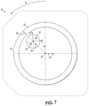
- FIG. 7 is a schematic illustration of the fiber optic connector of FIG. 6 with the core-to-ferrule offset minimized by rotating the fiber optic connector (and thus the ferrule);
- FIG. 8 is a schematic illustration of the fiber optic connector of FIG. 6 with the core-to-ferrule offset minimized by rotating the optical fiber;
- FIG. 9 is a flow chart of an exemplary method for minimizing the core-to-ferrule offset in accordance with an embodiment of the present disclosure.
- FIG. 10 is a graph illustrating ferrule and optical fiber distributions and separating the ferrules and optical fibers into groups.
- FIG. 11 is a schematic illustration of a method of selectively matching ferrules and optical fibers from respective groups illustrated in FIG. 10 .
- the description relates to a method for improving the alignment of optical fibers across an optical connection by minimizing the offset between the inner core of the optical fiber and a fixed mating location on the ferrule of a fiber optic connector.
- the mating location is the area or portion of the ferrule end face that includes the end of the optical fiber and is configured to engage, confront or otherwise optically “connect” to an optical fiber in the other optical component (e.g., another fiber optic connector).
- the position of the mating location may depend on several factors, including the type of fiber optic connector.
- the position of the fiber core becomes more predictably located at or near the intended mating location of the fiber optic connector.
- the insertion losses may be minimized since the respective inner cores of the optical fibers in the connectors are more likely to be aligned or more closely aligned than if the offsets were not minimized.
- the method in accordance with the present disclosure minimizes the offset between the fiber core and the mating location on the ferrule in a straightforward manner that avoids the high-cost approaches of the prior art.
- the reduction in insertion losses across an optical connection in accordance with aspects of the present disclosure may be achieved with existing materials, parts, and with minimal changes to current manufacturing techniques.
- the resulting reduction in insertion losses across an optical connection may be achieved in a cost-effective manner.
- FIGS. 3 and 3A are schematic illustrations of an exemplary geometry at a tip of a fiber optic connector, such as fiber optic connector 10 illustrated in FIG. 1 .
- the ferrule 12 includes an outer surface 30 that defines a center 32 (referred to as ferrule center 32 ).
- a coordinate system 34 may be positioned at ferrule center 32 that defines orthogonal axes x and y (e.g., a Cartesian coordinate system).
- the ferrule 12 includes a micro-bore 14 that is configured to receive the bare optical fiber 16 .
- the micro-bore 14 would be located such that the center 36 of the micro-bore 14 (referred to as bore center 36 ) coincides with the ferrule center 32 .
- a coordinate system 34 ′ may be positioned at bore center 36 that defines orthogonal axes x′ and y′. Due to inherent tolerance variations in the materials and manufacturing processes, however, the micro-bore 14 is typically offset from the ferrule center 32 by some amount ⁇ x 1 , ⁇ y 1 .
- the optical fiber 16 is configured to be positioned in the micro-bore 14 and secured within the micro-bore 14 using a suitable adhesive or bonding agent 38 .
- the micro-bore 14 is oversized relative to the optical fiber 16 such that the center 40 of the optical fiber 16 (referred to as fiber center 40 ) is typically offset from the bore center 36 by some amount ⁇ x 2 , ⁇ y 2 .
- the optical fiber 16 includes an inner core 42 and an outer cladding 44 .
- the inner core 42 would be located such that the center 46 of the inner core 42 (referred to as core center 46 ) coincides with the fiber center 40 .
- a coordinate system 34 ′′ may be positioned at fiber center 40 that defines orthogonal axes x′′ and y′′. Due to inherent tolerance variations in the materials and manufacturing processes, however, the core center 46 is typically offset from the fiber center 40 by some amount ⁇ x 3 , ⁇ y 3 .
- the position of the inner core 42 of the optical fiber 16 relative to the mating location of the ferrule 12 may have a wide range of variance. That variation is influenced at least in part by: i) the position of the micro-bore 14 within the ferrule 12 ; ii) the position of the optical fiber 16 within the micro-bore 14 ; and iii) the position of the inner core 42 within the optical fiber 16 .
- the challenge for reducing insertion losses is to locate the core center 46 as close as possible to the mating location on the ferrule 12 given the variations present in current materials and manufacturing techniques.
- the ferrule center 32 may operate as the mating location of the ferrule 12 , and the description below is premised on minimizing the offset between the center 46 of the inner core 42 and the center 32 of the ferrule 12 .
- This offset is referred to as the core-to-ferrule offset and indicates the deviation in the position of the inner core 42 from its intended position (i.e., at the mating location). While the description below provides the mating location at the ferrule center 32 , it should be recognized that aspects of the present disclosure also apply to embodiments where the mating location is not at the ferrule center 32 but at some other point on the ferrule 12 offset from the center 32 . The goal would then be to minimize the offset between the core center 46 and the off-center mating location of the ferrule in that embodiment.
- FIGS. 4-8 generally describe a method for minimizing the distance between the center 46 of the inner core 42 and the center 32 of the ferrule 12 (the core-to-ferrule offset) taking into account variations in the micro-bore 14 position within the ferrule 12 and variations in the inner core 42 position within the optical fiber 16 (i.e., numerals i) and iii) listed above).
- FIG. 4 is a schematic illustration of a ferrule 12 having an off-center micro-bore 14 .
- the ferrule 12 includes an outer surface 30 that defines the center 32 of the ferrule 12 .
- the coordinate system 34 is shown having its origin at the center 32 of the ferrule 12 .
- the position of the center 36 of the micro-bore 14 relative to the center 32 of the ferrule 12 may be characterized by a radial distance e 1 and a reference angle ⁇ 1 .
- the center 36 of the micro-bore 14 may be positioned at (e 1 , ⁇ 1 ) in cylindrical coordinates.
- the value e is referred to as the eccentricity and a is referred to as the bearing angle.
- the bore eccentricity is relative to the center 32 of the ferrule 12 and the bore bearing angle is relative to a reference axis, which may be the vertical axis (i.e., the positive y axis in FIG. 4 ). Other reference axes, however, may be possible.
- FIG. 5 is a schematic illustration of an optical fiber 16 having an off-center inner core 42 .
- the optical fiber 16 includes an outer surface 48 that defines the center 40 of the optical fiber 16 .
- the coordinate system 34 ′′ is shown having its origin at the center 40 of the optical fiber 16 .
- the position of the core center 46 of the inner core 42 relative to the fiber center 40 may be characterized by eccentricity e 2 and bearing angle ⁇ 2 .
- the core center 46 of the inner core 42 may be positioned at (e 2 , ⁇ 2 ) in cylindrical coordinates.
- the core eccentricity is relative to the center 40 of the optical fiber 16 and the core bearing angle is relative to a reference axis, which may be the vertical axis (i.e., the positive y′′ axis in FIG. 5 ).
- FIG. 6 illustrates the optical fiber 16 positioned within the micro-bore 14 with the ferrule 12 and the optical fiber 16 in the same orientation as provided in FIGS. 4 and 5 , respectively, and ignoring any offset due to the position of the optical fiber 16 in the micro-bore 14 . While the eccentricities of the micro-bore 14 and the inner core 42 relative to the ferrule center 32 and fiber center 40 , respectively, are fixed for a given ferrule 12 and optical fiber 16 pair, the relative orientation of the ferrule 12 and the optical fiber 16 may be manipulated in order to minimize the core-to-ferrule offset.
- the bearing angles ⁇ 1 and ⁇ 2 are arranged 180 degrees apart and the inner core 42 is radially inboard of the fiber center 40 , then the distance between the core center 46 and the ferrule center 32 will be minimized. This means that given a particular ferrule 12 and optical fiber 16 pair, the inner core 42 can be positioned as close as possible to the intended mating location of the ferrule 12 of fiber optic connector 10 .
- FIG. 7 illustrates the optical fiber 16 positioned within the micro-bore 14 with the ferrule 12 and the optical fiber 16 having an orientation such that the bearing angles ⁇ 1 and ⁇ 2 are 180 degrees apart.
- the arrangement of FIG. 7 may be achieved by maintaining the orientation of the optical fiber 16 while the ferrule 12 (or alternatively the entire fiber optic connector 10 ) is rotated about its central axis to achieve a 180-degree difference in the bearing angles ⁇ 1 , ⁇ 2 (demonstrated by arrow A).
- FIG. 8 is similar to FIG. 7 but where the orientation of the ferrule 12 is maintained and the optical fiber 16 is rotated to achieve a 180-degree difference in the bearing angles ⁇ 1 , ⁇ 2 (demonstrated by arrow B).
- both the ferrule 12 and the optical fiber 16 may be rotated to achieve the 180-degree difference in the bearing angles ⁇ 1 , ⁇ 2 .
- the ferrule 12 may be rotated such that micro-bore 14 is positioned upwardly from the ferrule center 32 (i.e., ⁇ 1 is 0 degrees) and the optical fiber 16 may be rotated such that the inner core 42 is positioned downwardly from the fiber center 40 (i.e., ⁇ 2 is 180 degrees).
- the ferrule 12 may be rotated before it is installed into the fiber optic connector such that micro-bore 14 is positioned upwardly (or other preferred direction with respect to an orientation key on the fiber optic connector) and the optical fiber 16 may be rotated such that the inner core 42 is positioned opposite to the direction of the micro-bore 14 .
- the relative rotations between the optical fiber 16 and the ferrule 12 in order to achieve the 180-degree difference in the bearing angles ⁇ 1 , ⁇ 2 may be prior to the insertion of the optical fiber 16 in the micro-bore 14 of the ferrule 12 .
- the method outlined above takes into account the offset in the position of the micro-bore 14 within the ferrule 12 and the offset of the inner core 42 within the optical fiber 16 to minimize the core-to-ferrule offset.
- the inner core 42 is positioned as close as possible to the intended mating location of the ferrule 12 (and fiber optic connector 10 ) given a particular ferrule 12 and optical fiber 16 pairing.
- the inner core 42 is positioned as close as possible to the fixed, known location where the fiber optic connector 10 is expected to connect to another optical component.
- the optical component to which the fiber optic connector 10 is configured to mate has also been “optimized” in the manner described above, then it is believed that a further reduction in the insertion losses across the optical connection will be achieved.
- the other optical component is another optical connector similar to fiber optic connector 10 , then the core-to-ferrule offset for the other fiber optic connector may be similarly minimized.
- the inner cores 42 are as close as possible to their intended mating location and the insertion losses across the optical connection will be reduced, and perhaps significantly reduced, compared to current fiber optic connectors (made according to conventional manufacturing techniques) and randomly mated across an optical connection.
- the variance as a result of the position of the optical fiber 16 within the micro-bore 14 may be reduced or eliminated. It is believed that reducing or eliminating this variance will further reduce the insertion losses across an optical connection. More particularly, one aspect of the method may include providing an interference fit between the optical fiber 16 and the micro-bore 14 . Such an interference fit essentially eliminates any play that might exist in positioning the optical fiber 16 within the micro-bore 14 and any potential offsets as a result of that play.
- the micro-bore 14 was sized just slightly larger than the optical fiber 16 to provide a clearance fit and a bonding agent 38 was used to secure the optical fiber 16 within the micro-bore 14 .
- the size of the optical fiber 16 may be sized to be the same or just slightly larger than the micro-bore 14 such that in the normal course, the optical fiber 16 is not able to fit into the micro-bore 14 at room temperature.
- the optical fiber 16 may be between less than about 1% larger than the size of the micro-bore 14 in the ferrule 12 , and preferably less than about 0.5% larger than the size of the micro-bore 14 in the ferrule 12 at room temperature.
- the diameter of the optical fiber 16 may be less than 0.5 microns (e.g., about 0.4 microns) larger than the diameter of the micro-bore 14 at room temperature.
- the ferrule 12 may be heated to a processing temperature above room temperature. Due to the thermal expansion of the ferrule material, the size of the micro-bore 14 in the ferrule 12 correspondingly increases.
- the micro-bore 14 may be configured to expand no greater than about 1%, and more likely no greater than about 0.5% as a result of the heating. In one embodiment, the micro-bore 14 may expand no greater than about 0.5 microns as a result of the heating.
- the micro-bore may expand about 0.43 microns when heated to about 350° C. and about 0.5 microns when heated to about 400° C. More particularly, the micro-bore 14 is configured to expand to a size that is substantially equal to or just slightly larger than the optical fiber 16 such that the optical fiber 16 may be inserted within the micro-bore 14 when the ferrule 12 is in a heated state. Subsequent to positioning the optical fiber 16 within the micro-bore 14 , the ferrule 12 may be cooled, causing the ferrule material to thermally contract.
- a typical ferrule e.g., Y2O3-stabilized zirconia
- the size of the micro-bore 14 correspondingly decreases to engage against the outer surface 48 of the optical fiber 16 and thereby form an interference fit between the optical fiber 16 and the micro-bore 14 of the ferrule 12 .
- any offsets resulting from the placement/movement of the optical fiber 16 in the micro-bore 14 may be effectively eliminated and the insertion losses across an optical connection may be further reduced.
- FIG. 9 is a flow chart outlining a method 58 for forming a population P t of optical fibers 16 terminated with fiber optic connectors, such as fiber optic connectors 10 , in accordance with aspects of the present disclosure.
- a population P f of ferrules 12 may be provided or selected from a greater group of ferrules 12 .
- Certain data about the ferrules 12 may then be determined by measurement and/or calculation.
- the micro-bore diameter D 1 , eccentricity e 1 , and bearing angle ⁇ 1 may be determined for each of the ferrules 12 in the population P f .
- the data about the ferrules 12 may be summarized as a mean micro-bore diameter ⁇ 1 and standard deviation ⁇ 1 .
- the eccentricity e 1 of the micro-bore 14 may be summarized with a standard deviation b 1 .
- the micro-bore 14 may be filled with a suitable bonding agent 38 for retaining the optical fiber 16 within the micro-bore 14 .
- the bonding agent 38 may have a composition including a partially cross-linked resin that is a polymer and a coupling agent that chemically bonds the partially cross-linked resin to the optical fiber 16 and the ferrule 12 .
- the melting point of the bonding agent may be at least 250° C., and more preferably at least 300° C.
- the viscosity of the bonding agent 38 is preferably less than 700 Pa s, more preferably less than 500 Pa s, and even more preferably less than 300 Pa s at the heated temperature of the ferrule 12 .
- the bonding agent 38 may include polyphenylene sulfide (PPS).
- PPS polyphenylene sulfide
- Other bonding agents, such as those disclosed in U.S. Pat. Nos. 8,696,215 and 9,568,686 (which are incorporated by reference herein in their entireties) may also be used.
- the fiber optic connector 10 may be assembled.
- the fiber optic connector 10 may be assembled but for the optical fiber 16 being coupled thereto (as well as some possible finishing steps, such as crimping, etc.).
- the ferrule 12 may be coupled to the ferrule holder 18 , such as through an over-molding process or by press fitting, and then that assembly may be positioned within the housing 20 .
- the assembly of the fiber optic connector 10 is generally well known in the industry and a further description will not be provided herein.
- the optical fiber 16 may be prepared for insertion into the ferrule 12 .
- the optical fiber 16 may be carried by a fiber optic cable (not shown) that includes a plurality of optical fibers 16 .
- the outer jacket of the fiber optic cable may be stripped to expose one or more optical fibers 16 carried by the fiber optic cable. If the optical fibers 16 are jacketed, then those jackets may be stripped to expose the bare optical fiber 16 , which as noted above includes the inner core 42 and the outer cladding 44 .
- Various stripping devices are known in the industry for stripping the outer jackets from optical fibers and/or fiber optic cables to thereby expose one or more bare optical fibers 16 . Accordingly, a further description of this process will not be provided herein.
- Certain data about the optical fiber 16 may then be determined by measurement and/or calculation. More particularly, in a next step 70 , the fiber diameter D 2 , eccentricity e 2 , and bearing angle ⁇ 2 may be determined for the optical fiber 16 .
- these variables may be measured using generally known techniques known to those of ordinary skill in the art.
- the data about the optical fibers 16 may be summarized as a mean diameter ⁇ 2 and standard deviation ⁇ 2 .
- the eccentricity e 2 of the inner core 42 may be summarized with a standard deviation b 2 .
- the ferrule 12 may be oriented relative to the optical fiber 16 so as to minimize the core-to-ferrule offset, i.e., the distance between the core center 46 of the inner core 42 and the center 32 of the ferrule 12 , which operates as the mating location in the described embodiment.
- the core-to-ferrule offset i.e., the distance between the core center 46 of the inner core 42 and the center 32 of the ferrule 12 , which operates as the mating location in the described embodiment.
- one way to achieve the desired orientation is to maintain the orientation of the optical fiber 16 and rotate the fiber optic connector 10 , and more particularly the ferrule 12 , until the bearing angles ⁇ 1 , ⁇ 2 are 180 degrees apart. In an exemplary embodiment, for example, this may be practiced by placing a marker 74 ( FIGS.
- the fiber optic connector 10 may then be rotated until the marker 74 and the core center 46 of the inner core 42 lie on a line that is through the ferrule center 32 .
- the marker 74 should be positioned radially outboard of the fiber center 40 , and the inner core 42 (and the core center 46 ) should be positioned radially inbound of the fiber center 40 .
- the marker 74 may be any indicia (e.g., a dot, arrow, dash, etc.) that indicates the direction of the bore eccentricity.
- the marker 74 may be placed in the end face of the ferrule 12 using any suitable technique, such as by laser etching. Other methods may also be possible.
- the fiber optic connector 10 may be held in position while the optical fiber 16 is rotated about its central axis until the marker 74 and the core center 46 lie on a line that is through the ferrule center 32 and are on opposite sides of the fiber center 40 similar to that described above.
- the fiber optic connector 10 may be rotated until the marker 74 lies along a vertical line in an upwardly position relative to ferrule center 32 , and the optical fiber 16 may be rotated until the inner core 42 lies along the vertical line in a downwardly position relative to the fiber center 40 .
- the ferrule 12 may be rotated before being installed into the fiber optic connector 10 such that the marker 74 points upwardly (or other preferred direction with respect to an orientation key on the fiber optic connector) and the optical fiber 16 may be rotated such that the inner core 42 is positioned opposite to the direction of the micro-bore 14 .
- the bearing angles ⁇ 1 , a 2 are 180 degrees apart.
- the ferrule 12 may be heated to a processing temperature T 1 above room temperature.
- the processing temperature T 1 should be sufficiently high to melt the bonding agent 38 within the micro-bore 14 of the ferrule 12 and to expand the size of the micro-bore 14 due to the thermal expansion of the ferrule material.
- the ferrule 12 may be heated to a processing temperature T 1 of greater than about 300° C., preferably greater than about 350° C., and more preferably greater than about 400° C.
- the manner in which the ferrule 12 is heated to the processing temperature T 1 is generally known in the art and thus will not be discussed in any further detail herein.
- the optical fiber 16 may be inserted into the micro-bore 14 of the ferrule 12 until the optical fiber 16 slightly extends from the end face of the ferrule 12 .
- Methods for inserting the optical fiber 16 within the micro-bore 14 are generally known in the art and thus will not be more fully described herein. In one embodiment, however, the feed rate Vi of the optical fiber 16 within the micro-bore 14 may be less than about 10 millimeters per second (mm/s), and more preferably less than about 5 mm/s.
- the ferrule 12 may be cooled.
- the ferrule 12 may be air cooled, such as by natural convection and/or by forced convection. Alternatively, liquid cooling may also be used.
- the ferrule 12 may be subjected to forced cooling for a first period of time, natural cooling for a second period of time, and then forced cooling for a third period of time. As the ferrule 12 cools, the ferrule material contracts about the optical fiber 16 to create an interference fit between the optical fiber 16 and the micro-bore 14 of the ferrule 12 to thereby secure the optical fiber 16 to the ferrule 12 and fiber optic connector 10 .
- An interference fit provides an improved connection between the optical fiber 16 and the fiber optic connector 10 .
- the fiber optic connector 10 may have a pull-out force larger than about 5 pounds (lbs) for pre-aged connectors and a pull-out force of larger than about 3 lbs for post-aged connectors.
- the fiber optic connector 10 has a fiber movement of less than about 30 mm, preferably less than about 20 mm, and even more preferably less than about 10 mm.
- any post processing steps on the fiber optic connector 10 may be performed. For example, various crimping and cleaving processes may be performed on the fiber optic connector 10 to ensure a secure connection between the optical fiber or fiber optic cable and the fiber optic connector 10 . Additionally, various polishing processes may be performed to ensure the end face of the ferrule 12 is properly shaped and free of debris or other defects that might degrade the optical signal across the optical connection.
- the post-processing steps are generally known to those of ordinary skill in the art and thus a further description will not be provided herein.
- the steps illustrated in FIG. 9 and described above may be repeated as needed to terminate a desired number of optical fibers 16 with fiber optic connectors 10 .
- one has a population P t of optical fibers 16 terminated with fiber optic connectors 10 wherein the position of the inner cores 42 of the optical fibers 16 are located very near to the intended mating location of the fiber optic connector 10 .
- fiber optic connectors 10 made in accordance with method 58 described above are mated together at an optical connection, such as in an adapter, it is believed that the insertion loss across the optical connection will be reduced as compared to current levels.
- IL insertion loss
- the methods disclosed herein result in fiber optic connectors with improved insertion loss performance as compared to the Grade B rating.
- fiber optic connectors of the present disclosure have insertion loss (IL) values as follows: IL mean ⁇ 0.07 dB and IL max ⁇ 0.15 dB for greater than 97% of the samples S. And achieving the improved insertion loss performance may for the most part be achieved using existing parts, materials and manufacturing processes. Thus, the reduction in insertion losses is gained with minimal cost and disruption to current production facilities.
- Method 58 describes forming an interference fit between the optical fiber 16 and the micro-bore 14 as a result of inserting the optical fiber 16 into the micro-bore 14 while the ferrule 12 is in a heated state and then cooling the ferrule 12 such that as the ferrule material contracts, the ferrule micro-bore 14 engages with the outer surface of the optical fiber 16 . While forming an interference fit is desirable for reducing insertion losses, forming such an interference fit may prove challenging in practice, especially given the variations in the diameters D 1 and D 2 of the micro-bores 14 and optical fibers 16 , respectively, across a population P f of the ferrules 12 and a population P o of optical fibers 16 made with current materials and manufacturing techniques.
- the diameter of the micro-bore 14 in the ferrule 12 is chosen to be sufficiently high relative to the diameter of the optical fiber 16 such that the optical fiber 16 will fit within the micro-bore 14 for every ferrule 12 and optical fiber 16 in the populations P f , P o of ferrules 12 and optical fibers 16 , respectively.
- the diameter of the micro-bore 14 is sufficiently large that D 1 ⁇ D 2 >0 for 100% of the ferrule and fiber populations P f , P o .
- This scenario provides for no interference fit between the optical fiber 16 and the ferrule 12 and thus can generate increased insertion losses for the fiber optic connector across an optical connection.
- the mean diameter ⁇ 1 of the micro-bore 14 is designed to be the same as the mean diameter ⁇ 2 of the optical fiber 16 (e.g., 125 microns), then given a typical distribution of bore and fiber diameters about these mean values and standard deviations at room temperature, one would expect the optical fiber 16 to fit within the micro-bore 14 for about 50% of the time. For the other 50% of the time, the optical fiber 16 would not fit within the micro-bore 14 , and the ferrule 12 would have to be scrapped (as opposed to the optical fiber, since the optical fiber may be part of a more expensive fiber optic cable). As such, a significant amount of scrap would be generated resulting in a cost prohibitive and inefficient production process.
- the diameter of the micro-bore 14 increases.
- heating the ferrule 12 to a processing temperature T 1 of between about 300° C. and about 400° C. will increase the micro-bore diameter by no more than about 1%, and more likely by no more than about 0.5%.
- the micro-bore diameter D 1 may increase by about 0.5 microns when the ferrule 12 is heated to a processing temperature T 1 of about 400° C.
- the number of optical fibers 16 (having a mean diameter of 125 microns) that will fit within the micro-bores 14 when the ferrule 12 is at the elevated temperature T 1 will be greater than that at room temperature. For example, given a typical distribution of bore and fiber diameters, it is expected that less than about 1% of the optical fibers 16 would not fit within the micro-bores 14 when the micro-bores have been expanded by no more than about 1%. Thus, the amount of scrap ferrules 12 may be significantly reduced by heating the ferrule 12 during insertion of the optical fiber 16 therein.
- the mean diameter ⁇ 1 of the micro-bore 14 of the ferrule 12 was selected to be equal to the mean diameter ⁇ 2 of the optical fiber 16 .
- the mean diameter ⁇ 2 of the optical fiber 16 is configured to be just slightly greater than the mean diameter ⁇ 1 of the micro-bore 14 , then the probability of an interference fit being formed between the micro-bore 14 of the ferrule 12 and the optical fiber 16 increases when using the heating and cooling techniques described above.
- the mean diameter ⁇ 2 of the optical fiber 16 may be selected to be larger than the mean diameter ⁇ 1 of the micro-bore 14 of the ferrules.
- the difference in the two mean diameters ⁇ 2 ⁇ 1 may be configured to meet a pre-determined criterion in order to achieve as many interference fits between the optical fibers 16 and the ferrules 12 without an excessive number of scrapped ferrules 12 due to the inability to fit within the micro-bores 14 .
- the mean diameters ⁇ 1 , ⁇ 2 of the micro-bores 14 of the ferrules 12 and the optical fibers 16 , respectively may be selected so that 0 ⁇ D 2 ⁇ D 1 ⁇ 0.4 ⁇ m for at least 25% of the population P t .
- the mean diameters ⁇ 2 of the micro-bores 14 of the ferrules 12 and the optical fibers 16 , respectively may be selected so that 0 ⁇ D 2 ⁇ D 1 ⁇ 0.4 ⁇ m, for at least 50% of the population P t .
- the mean diameters ⁇ 1 , ⁇ 2 of the micro-bores 14 of the ferrules 12 and the optical fibers 16 , respectively may be selected so that 0 ⁇ D 2 ⁇ D 1 ⁇ 0.4 ⁇ m, for at least 75% of the population P t .
- the mean diameters ⁇ 1 , ⁇ 2 of the micro-bores 14 of the ferrules 12 and the optical fibers 16 , respectively may be selected so that 0 ⁇ D 2 ⁇ D 1 ⁇ 0.4 ⁇ m, for at least 90% of the population P t .
- the number of optical fibers 16 that form an interference fit with the ferrules 12 is sufficiently high such that the number of scrapped ferrules 12 is sufficiently low and the insertion losses across an optical connection are reduced.
- the determining steps 62 , 70 for the two populations P f , P o may be performed before optical fibers 16 are connected to a respective ferrule 12 of a fiber optic connector 10 .
- the data may then be analyzed statistically by determining the mean ⁇ 1 , ⁇ 2 and standard deviation ⁇ 1 , ⁇ 2 for the ferrule 12 and optical fiber 16 populations P f , P o , respectively.
- the standard deviation b 1 , b 2 for the eccentricity e 1 , e 2 for the ferrule micro-bore 14 and inner core 42 locations for populations P f , P o , respectively, may also be analyzed. If the statistical data is “close enough” to each other, then the method may continue by connecting the optical fibers 16 to respective ferrules 12 of fiber optic connectors 10 as described in FIG. 9 above. If the statistical data does not match sufficiently closely to each other, then the process may not move forward and another ferrule population P f may be selected, for example. In an exemplary embodiment, the statistical data may be deemed close enough to each other if the statistical factors are within a specified range of each other. In one embodiment, for example, the ferrule population P f and the optical fiber population P o , may be acceptable when the statistical data falls into one or more, and preferably each, of the following ranges.
- a further reduction in the insertion loss across an optical connection of two mated connectors may be achieved by some level of selective matching between ferrule 12 and optical fiber 16 used to form the fiber optic connector 10 .
- the respective variables associated with the ferrules 12 and optical fibers 16 may be determined prior to other steps associated with coupling a select one of the optical fibers 16 to a select one of the ferrules 12 .
- steps 62 and 70 may be performed prior to the orienting step 72 , heating step 76 , insertion step 78 , and the coupling step 80 .
- the eccentricity e for each of the ferrules 12 and optical fibers 16 in their respective populations P f and P o are known prior to the optical fibers 16 being coupled to the ferrules 12 .
- the eccentricity is indicative of a radial offset, i.e., a radial distance from a reference point.
- the eccentricity e 1 of the micro-bore and the eccentricity e 2 of the inner core are substantially equal (and ignoring any offset due to the position of the optical fiber 16 within the bore, as noted by point ii) above)
- the core center 46 should be located at the ferrule center 32 and the core-to-center offset should be substantially zero. This means that the core center 46 is substantially exactly located at the mating location for the ferrule 12 and fiber optic connector 10 .
- FIGS. 10 and 11 are schematic illustrations of a method for selectively matching the ferrules 12 and the optical fibers 16 in accordance with an embodiment of the present disclosure.
- curve 1 represents a distribution of eccentricities e 1 associated with the micro-bores 14 of the ferrules 12
- curve 2 represents a distribution of eccentricities e 2 associated with the inner cores 42 of the optical fibers 16 .
- each of the distributions 1 , 2 may be divided into a plurality of regions.
- each of the distributions 1 , 2 may be divided into three regions, however fewer or more regions may be used.
- the distribution 1 for the micro-bore 14 eccentricities e 1 may be divided into three regions R A , R B , and R C .
- the first region R A may have a range between zero and a pre-determined value R a , 0 ⁇ R A ⁇ R a .
- the second region R B may have a range between R a and R b , R a ⁇ R B ⁇ R b , where R b is also a pre-determined value.
- the third region R C may have a range greater than R b , R C >R b .
- the values R a and R b may be determined by equally dividing the distribution 1 approximately into thirds based on total area under the curve, for example. Other ways for determining the values of R a and R b may also be used.
- the distribution 2 for the inner core 42 eccentricities e 2 may be divided into three regions R D , R E , and R F .
- the first region R D may have a range between zero and a pre-determined value R d , 0 ⁇ R D ⁇ R d .
- the second region R E may have a range between R d and R e , R d ⁇ R D ⁇ R e where R e is also a pre-determined value.
- the third region R F may have a range greater than R e , R F >R e .
- the values R d and R e may be determined by equally dividing the distribution 2 approximately into thirds based on total area under the curve, for example. Other ways for determining the values of R d and R e may also be used.
- the ferrules 12 and optical fibers 16 may be selected from corresponding regions.
- the core center 46 will be located closer to the ferrule center 32 for the population of fiber optic connectors 10 as compared to fiber optic connectors that were produced by randomly mating the ferrules 12 and optical fibers 16 in the populations P f and P o . Accordingly, a further reduction in insertion loss is expected across an optical connection formed by the fiber optic connectors produced from the selective matching process described above.
- Selective matching may be used for a population P f of ferrules 12 and a population P o of optical fibers 16 whether an interference fit and/or a clearance fit is intended between the ferrules 12 and the optical fibers 16 .
Landscapes
- Physics & Mathematics (AREA)
- General Physics & Mathematics (AREA)
- Optics & Photonics (AREA)
- Mechanical Coupling Of Light Guides (AREA)
Abstract
Description
The method may further include measuring an eccentricity of the micro-bore in each of the ferrules in the population; measuring an eccentricity of the inner core in each of the optical fibers in the population; separating the population of ferrules into a plurality of groups, each group having a different pre-determined range of eccentricities; separating the population of optical fibers into a plurality of groups, each group having a different pre-determined range of eccentricities, wherein the number of groups of ferrules and the number of groups of optical fibers is the same; ordering the groups of ferrules and groups of optical fibers by eccentricity; and performing the orienting, heating and securing steps using a selected ferrule and a selected optical fiber from corresponding groups of ferrules and optical fibers.
From a practical standpoint, if the current manufacturing techniques are to be retained, the only variable that might be controllable is the diameter D1 of the micro-bores 14 in the
Claims (23)
Priority Applications (1)
| Application Number | Priority Date | Filing Date | Title |
|---|---|---|---|
| US17/175,475 US11280967B2 (en) | 2019-11-29 | 2021-02-12 | Method for making a low-loss fiber optic connector |
Applications Claiming Priority (3)
| Application Number | Priority Date | Filing Date | Title |
|---|---|---|---|
| US201962941990P | 2019-11-29 | 2019-11-29 | |
| US17/097,185 US11467350B2 (en) | 2019-11-29 | 2020-11-13 | Method for making a low-loss fiber optic connector |
| US17/175,475 US11280967B2 (en) | 2019-11-29 | 2021-02-12 | Method for making a low-loss fiber optic connector |
Related Parent Applications (1)
| Application Number | Title | Priority Date | Filing Date |
|---|---|---|---|
| US17/097,185 Continuation US11467350B2 (en) | 2019-11-29 | 2020-11-13 | Method for making a low-loss fiber optic connector |
Publications (2)
| Publication Number | Publication Date |
|---|---|
| US20210165172A1 US20210165172A1 (en) | 2021-06-03 |
| US11280967B2 true US11280967B2 (en) | 2022-03-22 |
Family
ID=73452088
Family Applications (5)
| Application Number | Title | Priority Date | Filing Date |
|---|---|---|---|
| US17/097,185 Active US11467350B2 (en) | 2019-11-29 | 2020-11-13 | Method for making a low-loss fiber optic connector |
| US17/175,475 Active US11280967B2 (en) | 2019-11-29 | 2021-02-12 | Method for making a low-loss fiber optic connector |
| US17/962,697 Active US11822129B1 (en) | 2019-11-29 | 2022-10-10 | Method for making a low-loss fiber optic connector |
| US18/486,195 Active US12210195B2 (en) | 2019-11-29 | 2023-10-13 | Method for making a low-loss fiber optic connector |
| US18/985,421 Pending US20250116825A1 (en) | 2019-11-29 | 2024-12-18 | Method for making a low-loss fiber optic connector |
Family Applications Before (1)
| Application Number | Title | Priority Date | Filing Date |
|---|---|---|---|
| US17/097,185 Active US11467350B2 (en) | 2019-11-29 | 2020-11-13 | Method for making a low-loss fiber optic connector |
Family Applications After (3)
| Application Number | Title | Priority Date | Filing Date |
|---|---|---|---|
| US17/962,697 Active US11822129B1 (en) | 2019-11-29 | 2022-10-10 | Method for making a low-loss fiber optic connector |
| US18/486,195 Active US12210195B2 (en) | 2019-11-29 | 2023-10-13 | Method for making a low-loss fiber optic connector |
| US18/985,421 Pending US20250116825A1 (en) | 2019-11-29 | 2024-12-18 | Method for making a low-loss fiber optic connector |
Country Status (2)
| Country | Link |
|---|---|
| US (5) | US11467350B2 (en) |
| EP (2) | EP3828608B1 (en) |
Cited By (1)
| Publication number | Priority date | Publication date | Assignee | Title |
|---|---|---|---|---|
| US11822129B1 (en) * | 2019-11-29 | 2023-11-21 | Corning Research & Development Corporation | Method for making a low-loss fiber optic connector |
Citations (12)
| Publication number | Priority date | Publication date | Assignee | Title |
|---|---|---|---|---|
| JPH0588045A (en) | 1991-09-26 | 1993-04-09 | Furukawa Electric Co Ltd:The | How to attach the optical fiber to the optical connector |
| US6742936B1 (en) | 2000-11-06 | 2004-06-01 | Corning Cable Systems Llc | Low-loss intermatable ferrules for optical fibers and a method of fabrication thereof |
| US8104974B1 (en) * | 2010-07-30 | 2012-01-31 | Tyco Electronics Corporation | Mating of optical fibers having angled end faces |
| US20130343709A1 (en) | 2012-06-22 | 2013-12-26 | Jeffrey Dean Danley | Ferrule assemblies employing mechanical interfaces for optical fibers, and related components and methods |
| US20140064665A1 (en) | 2012-02-20 | 2014-03-06 | Adc Telecommunications, Inc. | Fiber Optic Connector, Fiber Optic Connector and Cable Assembly, and Methods for Manufacturing |
| US8696215B1 (en) * | 2012-10-15 | 2014-04-15 | Corning Cable Systems Llc | Adhesive compositions including partially cross-linked resins and coupling agents and methods for use thereof |
| WO2015068122A1 (en) | 2013-11-07 | 2015-05-14 | Tyco Electronics (Shanghai) Co. Ltd. | Ferrule and method for manufacturing the same, fiber optic connector |
| US9568686B2 (en) | 2012-10-15 | 2017-02-14 | Corning Optical Communications LLC | Optical connector and ferrule adhesion system including adhesive composition, and related methods |
| US9891390B2 (en) | 2013-11-07 | 2018-02-13 | Adc Telecommunications (Shanghai) Distribution Co., Ltd. | Fiber optic connector assembly and method for manufacturing the same |
| US10185096B2 (en) | 2013-12-19 | 2019-01-22 | Corning Optical Communications LLC | Ferrule-core concentricity measurement systems and methods |
| US10488600B2 (en) * | 2016-08-23 | 2019-11-26 | Corning Optical Communications LLC | Methods of securing an optical fiber within an optical fiber connector using a heating apparatus |
| US20200073067A1 (en) | 2017-05-18 | 2020-03-05 | Corning Research & Development Corporation | Fiber optic connector with polymeric material between fiber end and ferrule end, and fabrication method |
Family Cites Families (3)
| Publication number | Priority date | Publication date | Assignee | Title |
|---|---|---|---|---|
| JP6287084B2 (en) * | 2012-11-09 | 2018-03-07 | 住友電気工業株式会社 | Optical integrated device, optical module |
| US9304264B2 (en) * | 2013-04-26 | 2016-04-05 | Tyco Electronics Corporation | Optical fiber subassembly |
| US11467350B2 (en) * | 2019-11-29 | 2022-10-11 | Corning Research & Development Corporation | Method for making a low-loss fiber optic connector |
-
2020
- 2020-11-13 US US17/097,185 patent/US11467350B2/en active Active
- 2020-11-16 EP EP20207823.4A patent/EP3828608B1/en active Active
- 2020-11-16 EP EP25211392.3A patent/EP4664172A3/en active Pending
-
2021
- 2021-02-12 US US17/175,475 patent/US11280967B2/en active Active
-
2022
- 2022-10-10 US US17/962,697 patent/US11822129B1/en active Active
-
2023
- 2023-10-13 US US18/486,195 patent/US12210195B2/en active Active
-
2024
- 2024-12-18 US US18/985,421 patent/US20250116825A1/en active Pending
Patent Citations (12)
| Publication number | Priority date | Publication date | Assignee | Title |
|---|---|---|---|---|
| JPH0588045A (en) | 1991-09-26 | 1993-04-09 | Furukawa Electric Co Ltd:The | How to attach the optical fiber to the optical connector |
| US6742936B1 (en) | 2000-11-06 | 2004-06-01 | Corning Cable Systems Llc | Low-loss intermatable ferrules for optical fibers and a method of fabrication thereof |
| US8104974B1 (en) * | 2010-07-30 | 2012-01-31 | Tyco Electronics Corporation | Mating of optical fibers having angled end faces |
| US20140064665A1 (en) | 2012-02-20 | 2014-03-06 | Adc Telecommunications, Inc. | Fiber Optic Connector, Fiber Optic Connector and Cable Assembly, and Methods for Manufacturing |
| US20130343709A1 (en) | 2012-06-22 | 2013-12-26 | Jeffrey Dean Danley | Ferrule assemblies employing mechanical interfaces for optical fibers, and related components and methods |
| US8696215B1 (en) * | 2012-10-15 | 2014-04-15 | Corning Cable Systems Llc | Adhesive compositions including partially cross-linked resins and coupling agents and methods for use thereof |
| US9568686B2 (en) | 2012-10-15 | 2017-02-14 | Corning Optical Communications LLC | Optical connector and ferrule adhesion system including adhesive composition, and related methods |
| WO2015068122A1 (en) | 2013-11-07 | 2015-05-14 | Tyco Electronics (Shanghai) Co. Ltd. | Ferrule and method for manufacturing the same, fiber optic connector |
| US9891390B2 (en) | 2013-11-07 | 2018-02-13 | Adc Telecommunications (Shanghai) Distribution Co., Ltd. | Fiber optic connector assembly and method for manufacturing the same |
| US10185096B2 (en) | 2013-12-19 | 2019-01-22 | Corning Optical Communications LLC | Ferrule-core concentricity measurement systems and methods |
| US10488600B2 (en) * | 2016-08-23 | 2019-11-26 | Corning Optical Communications LLC | Methods of securing an optical fiber within an optical fiber connector using a heating apparatus |
| US20200073067A1 (en) | 2017-05-18 | 2020-03-05 | Corning Research & Development Corporation | Fiber optic connector with polymeric material between fiber end and ferrule end, and fabrication method |
Non-Patent Citations (2)
| Title |
|---|
| European Patent Application No. 20207823.4 Extended European Search Report dated Mar. 31, 2021; 9 pages; European Patent Office. |
| R. Schultz, "Rapid Field Termination of an SMA Fiber Optic Connector", Proceedings of the Optical Fiber Conference, Los Angeles, Sep. 1982, pp. 165-170. |
Cited By (2)
| Publication number | Priority date | Publication date | Assignee | Title |
|---|---|---|---|---|
| US11822129B1 (en) * | 2019-11-29 | 2023-11-21 | Corning Research & Development Corporation | Method for making a low-loss fiber optic connector |
| US12210195B2 (en) | 2019-11-29 | 2025-01-28 | Corning Research & Development Corporation | Method for making a low-loss fiber optic connector |
Also Published As
| Publication number | Publication date |
|---|---|
| US20240036267A1 (en) | 2024-02-01 |
| EP4664172A2 (en) | 2025-12-17 |
| EP3828608B1 (en) | 2025-12-17 |
| US20210165171A1 (en) | 2021-06-03 |
| US12210195B2 (en) | 2025-01-28 |
| US11822129B1 (en) | 2023-11-21 |
| US20250116825A1 (en) | 2025-04-10 |
| US20210165172A1 (en) | 2021-06-03 |
| EP3828608A1 (en) | 2021-06-02 |
| US11467350B2 (en) | 2022-10-11 |
| EP4664172A3 (en) | 2026-03-11 |
Similar Documents
| Publication | Publication Date | Title |
|---|---|---|
| US4738508A (en) | Terminated optical fiber and methods of making | |
| US5845028A (en) | Alignment assembly for multifiber or single fiber optical cable connector | |
| CN103597389B (en) | Optical fiber connector ferrule having open fiber clamping grooves | |
| EP1010998B1 (en) | Alignment sleeves for interconnecting optical ferrules of dissimilar size, and methods for making same | |
| EP0381513B1 (en) | Mechanical connection for polarization-maintaining optical fiber and methods of making | |
| US20250116825A1 (en) | Method for making a low-loss fiber optic connector | |
| US11320600B2 (en) | Fiber optic connector for hardware interiors and method of using same | |
| US20250251551A1 (en) | Fiber optic assemblies including a bonding agent, along with related methods | |
| US20130343709A1 (en) | Ferrule assemblies employing mechanical interfaces for optical fibers, and related components and methods | |
| EP0112379B1 (en) | Fabrication of optical connectors | |
| EP1010999A2 (en) | V-groove adapters for interconnecting optical conductors, and methods for making same | |
| Nawata | Multimode and single-mode fiber connectors technology | |
| CA2342298A1 (en) | Optical connector | |
| CA2334129A1 (en) | Multi-fiber array connector | |
| EP1491925B1 (en) | Optical fiber cable connector assembly with strain relief | |
| JPH04273204A (en) | Optical fiber terminal | |
| US7274845B2 (en) | Low-cost method and apparatus for establishing fiber optic connections | |
| US11644623B2 (en) | Duplex MOST connector | |
| Satake | The history of the MT and its variations | |
| Drake | A critical review of fiber optic connectors |
Legal Events
| Date | Code | Title | Description |
|---|---|---|---|
| FEPP | Fee payment procedure |
Free format text: ENTITY STATUS SET TO UNDISCOUNTED (ORIGINAL EVENT CODE: BIG.); ENTITY STATUS OF PATENT OWNER: LARGE ENTITY |
|
| AS | Assignment |
Owner name: CORNING RESEARCH & DEVELOPMENT CORPORATION, NEW YORK Free format text: ASSIGNMENT OF ASSIGNORS INTEREST;ASSIGNORS:BOBEN, RAISA ROSE;DOCKCHOORUNG, WORAPHAT;FREELAND, RILEY SAUNDERS;AND OTHERS;SIGNING DATES FROM 20201110 TO 20210212;REEL/FRAME:055709/0850 |
|
| STPP | Information on status: patent application and granting procedure in general |
Free format text: RESPONSE TO NON-FINAL OFFICE ACTION ENTERED AND FORWARDED TO EXAMINER |
|
| STPP | Information on status: patent application and granting procedure in general |
Free format text: NON FINAL ACTION MAILED |
|
| STPP | Information on status: patent application and granting procedure in general |
Free format text: RESPONSE TO NON-FINAL OFFICE ACTION ENTERED AND FORWARDED TO EXAMINER |
|
| STPP | Information on status: patent application and granting procedure in general |
Free format text: NOTICE OF ALLOWANCE MAILED -- APPLICATION RECEIVED IN OFFICE OF PUBLICATIONS |
|
| STPP | Information on status: patent application and granting procedure in general |
Free format text: AWAITING TC RESP., ISSUE FEE NOT PAID |
|
| STPP | Information on status: patent application and granting procedure in general |
Free format text: NOTICE OF ALLOWANCE MAILED -- APPLICATION RECEIVED IN OFFICE OF PUBLICATIONS |
|
| STCF | Information on status: patent grant |
Free format text: PATENTED CASE |
|
| AS | Assignment |
Owner name: CORNING RESEARCH & DEVELOPMENT CORPORATION, NEW YORK Free format text: ASSIGNMENT OF ASSIGNORS INTEREST;ASSIGNOR:ZUJEWSKI, MATEUSZ TOMASZ;REEL/FRAME:068104/0644 Effective date: 20240710 |
|
| CC | Certificate of correction | ||
| MAFP | Maintenance fee payment |
Free format text: PAYMENT OF MAINTENANCE FEE, 4TH YEAR, LARGE ENTITY (ORIGINAL EVENT CODE: M1551); ENTITY STATUS OF PATENT OWNER: LARGE ENTITY Year of fee payment: 4 |