US11279618B2 - Ozone water supply apparatus and ozone generation device - Google Patents
Ozone water supply apparatus and ozone generation device Download PDFInfo
- Publication number
- US11279618B2 US11279618B2 US16/809,550 US202016809550A US11279618B2 US 11279618 B2 US11279618 B2 US 11279618B2 US 202016809550 A US202016809550 A US 202016809550A US 11279618 B2 US11279618 B2 US 11279618B2
- Authority
- US
- United States
- Prior art keywords
- ozone
- tube
- entrance
- transparent tube
- circuit unit
- Prior art date
- Legal status (The legal status is an assumption and is not a legal conclusion. Google has not performed a legal analysis and makes no representation as to the accuracy of the status listed.)
- Expired - Fee Related, expires
Links
Images


Classifications
-
- C—CHEMISTRY; METALLURGY
- C01—INORGANIC CHEMISTRY
- C01B—NON-METALLIC ELEMENTS; COMPOUNDS THEREOF; METALLOIDS OR COMPOUNDS THEREOF NOT COVERED BY SUBCLASS C01C
- C01B13/00—Oxygen; Ozone; Oxides or hydroxides in general
- C01B13/10—Preparation of ozone
- C01B13/11—Preparation of ozone by electric discharge
- C01B13/115—Preparation of ozone by electric discharge characterised by the electrical circuits producing the electrical discharge
-
- A—HUMAN NECESSITIES
- A61—MEDICAL OR VETERINARY SCIENCE; HYGIENE
- A61L—METHODS OR APPARATUS FOR STERILISING MATERIALS OR OBJECTS IN GENERAL; DISINFECTION, STERILISATION OR DEODORISATION OF AIR; CHEMICAL ASPECTS OF BANDAGES, DRESSINGS, ABSORBENT PADS OR SURGICAL ARTICLES; MATERIALS FOR BANDAGES, DRESSINGS, ABSORBENT PADS OR SURGICAL ARTICLES
- A61L2/00—Disinfection or sterilisation of materials or objects, in general; Accessories therefor
- A61L2/16—Disinfection or sterilisation of materials or objects, in general; Accessories therefor using chemical substances
- A61L2/18—Liquid substances
- A61L2/183—Ozone dissolved in a liquid
-
- A—HUMAN NECESSITIES
- A61—MEDICAL OR VETERINARY SCIENCE; HYGIENE
- A61L—METHODS OR APPARATUS FOR STERILISING MATERIALS OR OBJECTS IN GENERAL; DISINFECTION, STERILISATION OR DEODORISATION OF AIR; CHEMICAL ASPECTS OF BANDAGES, DRESSINGS, ABSORBENT PADS OR SURGICAL ARTICLES; MATERIALS FOR BANDAGES, DRESSINGS, ABSORBENT PADS OR SURGICAL ARTICLES
- A61L2/00—Disinfection or sterilisation of materials or objects, in general; Accessories therefor
- A61L2/26—Accessories
-
- C—CHEMISTRY; METALLURGY
- C01—INORGANIC CHEMISTRY
- C01B—NON-METALLIC ELEMENTS; COMPOUNDS THEREOF; METALLOIDS OR COMPOUNDS THEREOF NOT COVERED BY SUBCLASS C01C
- C01B13/00—Oxygen; Ozone; Oxides or hydroxides in general
- C01B13/10—Preparation of ozone
- C01B13/11—Preparation of ozone by electric discharge
-
- C—CHEMISTRY; METALLURGY
- C02—TREATMENT OF WATER, WASTE WATER, SEWAGE, OR SLUDGE
- C02F—TREATMENT OF WATER, WASTE WATER, SEWAGE, OR SLUDGE
- C02F1/00—Treatment of water, waste water, or sewage
- C02F1/72—Treatment of water, waste water, or sewage by oxidation
- C02F1/78—Treatment of water, waste water, or sewage by oxidation with ozone
-
- E—FIXED CONSTRUCTIONS
- E03—WATER SUPPLY; SEWERAGE
- E03C—DOMESTIC PLUMBING INSTALLATIONS FOR FRESH WATER OR WASTE WATER; SINKS
- E03C1/00—Domestic plumbing installations for fresh water or waste water; Sinks
- E03C1/02—Plumbing installations for fresh water
- E03C1/04—Water-basin installations specially adapted to wash-basins or baths
- E03C1/0404—Constructional or functional features of the spout
-
- A—HUMAN NECESSITIES
- A61—MEDICAL OR VETERINARY SCIENCE; HYGIENE
- A61L—METHODS OR APPARATUS FOR STERILISING MATERIALS OR OBJECTS IN GENERAL; DISINFECTION, STERILISATION OR DEODORISATION OF AIR; CHEMICAL ASPECTS OF BANDAGES, DRESSINGS, ABSORBENT PADS OR SURGICAL ARTICLES; MATERIALS FOR BANDAGES, DRESSINGS, ABSORBENT PADS OR SURGICAL ARTICLES
- A61L2202/00—Aspects relating to methods or apparatus for disinfecting or sterilising materials or objects
- A61L2202/10—Apparatus features
- A61L2202/11—Apparatus for generating biocidal substances, e.g. vaporisers, UV lamps
-
- C—CHEMISTRY; METALLURGY
- C01—INORGANIC CHEMISTRY
- C01B—NON-METALLIC ELEMENTS; COMPOUNDS THEREOF; METALLOIDS OR COMPOUNDS THEREOF NOT COVERED BY SUBCLASS C01C
- C01B2201/00—Preparation of ozone by electrical discharge
- C01B2201/60—Feed streams for electrical dischargers
- C01B2201/62—Air
-
- C—CHEMISTRY; METALLURGY
- C02—TREATMENT OF WATER, WASTE WATER, SEWAGE, OR SLUDGE
- C02F—TREATMENT OF WATER, WASTE WATER, SEWAGE, OR SLUDGE
- C02F2201/00—Apparatus for treatment of water, waste water or sewage
- C02F2201/78—Details relating to ozone treatment devices
- C02F2201/782—Ozone generators
-
- C—CHEMISTRY; METALLURGY
- C02—TREATMENT OF WATER, WASTE WATER, SEWAGE, OR SLUDGE
- C02F—TREATMENT OF WATER, WASTE WATER, SEWAGE, OR SLUDGE
- C02F2201/00—Apparatus for treatment of water, waste water or sewage
- C02F2201/78—Details relating to ozone treatment devices
- C02F2201/784—Diffusers or nozzles for ozonation
-
- C—CHEMISTRY; METALLURGY
- C02—TREATMENT OF WATER, WASTE WATER, SEWAGE, OR SLUDGE
- C02F—TREATMENT OF WATER, WASTE WATER, SEWAGE, OR SLUDGE
- C02F2303/00—Specific treatment goals
- C02F2303/02—Odour removal or prevention of malodour
-
- C—CHEMISTRY; METALLURGY
- C02—TREATMENT OF WATER, WASTE WATER, SEWAGE, OR SLUDGE
- C02F—TREATMENT OF WATER, WASTE WATER, SEWAGE, OR SLUDGE
- C02F2303/00—Specific treatment goals
- C02F2303/04—Disinfection
-
- C—CHEMISTRY; METALLURGY
- C02—TREATMENT OF WATER, WASTE WATER, SEWAGE, OR SLUDGE
- C02F—TREATMENT OF WATER, WASTE WATER, SEWAGE, OR SLUDGE
- C02F2307/00—Location of water treatment or water treatment device
- C02F2307/06—Mounted on or being part of a faucet, shower handle or showerhead
-
- E—FIXED CONSTRUCTIONS
- E03—WATER SUPPLY; SEWERAGE
- E03C—DOMESTIC PLUMBING INSTALLATIONS FOR FRESH WATER OR WASTE WATER; SINKS
- E03C2201/00—Details, devices or methods not otherwise provided for
- E03C2201/40—Arrangement of water treatment devices in domestic plumbing installations
Definitions
- the present disclosure relates to a fluid supply apparatus, and more particularly to an ozone water supply apparatus and an ozone generation device.
- Ozone water has sterilizing and deodorizing effects, so that the ozone water is widely used in various fields (e.g., as a tableware disinfectant or a medical device disinfectant).
- Conventional ozone generation devices use the operation principle of a Venturi tube to mix ozone and water with each other.
- how ozone can be instantaneously mixed with water when supplying water has become an important subject in this field.
- the present disclosure provides an ozone water supply apparatus and an ozone generation device to effectively improve the issues associated with conventional ozone generation devices.
- the present disclosure provides an ozone water supply apparatus, which includes a faucet device and an ozone generation device.
- the ozone generation device includes a Venturi tube and an ozone generation module.
- the Venturi tube includes a first entrance connected to the faucet device, a second entrance, and an exit. When water flows from the faucet device to the Venturi tube through the first entrance and flows out of the Venturi tube through the exit, the Venturi tube is configured to form a negative pressure at the second entrance.
- the ozone generation module includes a circuit unit, at least one ozone-activated tube, and a launcher. The at least one ozone-activated tube is electrically coupled to the circuit unit and is in spatial communication with the Venturi tube through the second entrance.
- the launcher is electrically coupled to the circuit unit, and includes a top retainer, a bottom retainer, a first transparent tube, a floating body, at least one first optical detector, a second transparent tube, a horizontal member, and a second optical detector.
- the bottom retainer is spaced apart from the top retainer along a vertical direction.
- the top retainer has an air-flow exit in spatial communication with the at least one ozone-activated tube, and the bottom retainer has an air-flow entrance.
- the first transparent tube has two opposite ends respectively fixed to the top retainer and the bottom retainer and being respectively in spatial communication with the air-flow exit and the air-flow entrance.
- the floating body is arranged in the first transparent tube.
- the at least one first optical detector is electrically coupled to the circuit unit and is arranged outside of the first transparent tube for detecting a movement of the floating body.
- the second transparent tube has two ends respectively fixed to the top retainer and the bottom retainer.
- the second transparent tube has a space therein.
- the horizontal member is arranged in the second transparent tube. When the ozone generation module is at a slanting position by an external force, the horizontal member is moved along the second transparent tube.
- the second optical detector is electrically coupled to the circuit unit and is arranged outside of the second transparent tube for detecting a movement of the horizontal member.
- the second optical detector When the second optical detector obtains that the ozone generation module is at the slanting position by detecting the movement of the horizontal member, the second optical detector stops the operation of the ozone generation module through the circuit unit.
- the Venturi tube forms the negative pressure at the second entrance, the gas flows into the at least one ozone-activated tube by passing through the air-flow entrance, the first transparent tube, and the air-flow exit so as to drive the floating body to move from the bottom retainer toward the top retainer.
- the at least one first optical detector drives the at least one ozone-activated tube through the circuit unit, so that at least one ozone-activated tube excites the gas to become an ozone that flows toward the second entrance.
- the present disclosure provides an ozone generation device, which includes a Venturi tube and an ozone generation module.
- the Venturi tube includes a first entrance, a second entrance, and an exit.
- the Venturi tube is configured to provide a water to flow there-into through the first entrance and to flow there-out through the exit so as to form a negative pressure at the second entrance.
- the ozone generation module includes a circuit unit, at least one ozone-activated tube, and a launcher.
- the at least one ozone-activated tube is electrically coupled to the circuit unit and is in spatial communication with the Venturi tube through the second entrance.
- the launcher is electrically coupled to the circuit unit, and includes a top retainer, a bottom retainer, a first transparent tube, a floating body, at least one first optical detector, a second transparent tube, a horizontal member, and a second optical detector.
- the bottom retainer is spaced apart from the top retainer along a vertical direction.
- the top retainer has an air-flow exit in spatial communication with the at least one ozone-activated tube, and the bottom retainer has an air-flow entrance.
- the first transparent tube has two opposite ends respectively fixed to the top retainer and the bottom retainer and being respectively in spatial communication with the air-flow exit and the air-flow entrance.
- the floating body is arranged in the first transparent tube.
- the at least one first optical detector is electrically coupled to the circuit unit and is arranged outside of the first transparent tube for detecting a movement of the floating body.
- the second transparent tube has two ends respectively fixed to the top retainer and the bottom retainer.
- the second transparent tube has a space therein.
- the horizontal member is arranged in the second transparent tube. When the ozone generation module is at a slanting position by an external force, the horizontal member is moved along the second transparent tube.
- the second optical detector is electrically coupled to the circuit unit and is arranged outside of the second transparent tube for detecting a movement of the horizontal member.
- the second optical detector When the second optical detector obtains that the ozone generation module is at the slanting position by detecting the movement of the horizontal member, the second optical detector stops the operation of the ozone generation module through the circuit unit.
- the Venturi tube forms the negative pressure at the second entrance, the gas flows into the at least one ozone-activated tube by passing through the air-flow entrance, the first transparent tube, and the air-flow exit so as to drive the floating body to move from the bottom retainer toward the top retainer.
- the at least one first optical detector drives the at least one ozone-activated tube through the circuit unit, so that at least one ozone-activated tube excites the gas to become an ozone that flows toward the second entrance.
- the ozone water supply apparatus or the ozone generation device of the present disclosure can use the negative pressure generated by the structure of the Venturi tube to drive the gas to blow against and move the floating body, so that the first optical detector can detect the movement of the floating body to instantly obtain a time point at which an ozone needs to be generated. Accordingly, the ozone-activated tube can instantly generate ozone toward the Venturi tube.
- FIG. 1 is a schematic view of an ozone water supply apparatus according to an embodiment of the present disclosure.
- FIG. 2 is a schematic view of an ozone generation device according to the embodiment of the present disclosure.
- FIG. 3 is a perspective view of a launcher of the ozone generation device according to the embodiment of the present disclosure.
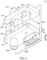
- FIG. 4 is a perspective view of the launcher of the ozone generation device from another angle of view according to the embodiment of the present disclosure.
- FIG. 5 is a cross-sectional view taken along line V-V of FIG. 3 .
- FIG. 6 is a cross-sectional view showing another configuration of FIG. 5 .
- FIG. 7 is a cross-sectional view showing the launcher when the second entrance of the Venturi tube is at the negative pressure.
- FIG. 8 is a cross-sectional view showing the launcher when the ozone generation device is at a slanting position.
- Numbering terms such as “first”, “second” or “third” can be used to describe various components, signals or the like, which are for distinguishing one component/signal from another one only, and are not intended to, nor should be construed to impose any substantive limitations on the components, signals or the like.
- an embodiment of the present disclosure provides an ozone water supply apparatus.
- the ozone water supply apparatus in the present embodiment includes a faucet device 200 and an ozone generation device 100 assembled to the faucet device 200 .
- the configuration of the faucet device 200 can be adjusted or changed according to design requirements, and the present disclosure is not limited thereto.
- the faucet device 200 of the present disclosure can be a kitchen faucet or a bathroom faucet.
- the ozone generation device 100 in the present embodiment is used in cooperation with the faucet device 200 , but the present disclosure is not limited thereto.
- the ozone generation device 100 can be independently applied (e.g., sold) or can be used in cooperation with other devices (e.g., a pipe of a urinal).
- the ozone generation device 100 includes a Venturi tube 1 , an ozone generation module 2 connected to the Venturi tube 1 , and a housing 3 that receives the ozone generation module 2 therein.
- the Venturi tube 1 is arranged outside of the housing 3 .
- the ozone generation module 2 in the present embodiment is arranged in the housing 3 , but in other embodiments of the present disclosure, the ozone generation device 100 can be provided without the housing 3 .
- the Venturi tube 1 includes a first entrance 11 (i.e., a liquid entrance), a second entrance 12 (i.e., a gas entrance), and an exit 13 (i.e., a gas-liquid mixed exit).
- the first entrance 11 of the Venturi tube 1 is connected to the faucet device 200 .
- the Venturi tube 1 is configured to form a negative pressure at the second entrance 12 .
- the negative pressure in the present embodiment results in a gas G flowing into the Venturi tube 1 through the second entrance 12 .
- the ozone generation module 2 includes a circuit unit 21 , two ozone-activated tubes 22 electrically coupled to the circuit unit 21 , a common pipe 23 connected to the two ozone-activated tubes 22 , and a launcher 24 that is electrically coupled to the circuit unit 21 .
- the number of the ozone-activated tubes 22 of the ozone generation module 2 in the present embodiment is two, but the present disclosure is not limited thereto.
- the ozone generation module 2 can include only one ozone-activated tube 22 and not include the common pipe 23 , and the ozone-activated tube 22 is detachably assembled in the housing 3 and is in spatial communication with the second entrance 12 of the Venturi tube 1 . Accordingly, the number of the ozone-activated tube 22 in the ozone generation module 2 of the present disclosure can be at least one.
- the circuit unit 21 includes a circuit board 211 , a plurality of electrical connectors 212 mounted on the circuit board 211 , and a water-proof adhesive 213 .
- the circuit board 211 is substantially embedded in the water-proof adhesive 213 , the electrical connectors 212 are exposed from the water-proof adhesive 213 , and the circuit board 211 is electrically coupled to the two ozone-activated tubes 22 and the launcher 24 through the electrical connectors 212 .
- circuit board 211 (excluding a portion of the circuit board 211 connected to the electrical connectors 212 ) is embedded in the water-proof adhesive 213 , so that the circuit board 211 in the present embodiment is electrically coupled to other components only through the electrical connectors 212 . Accordingly, the circuit board 211 in the present embodiment, which is easily damaged by moisture, is embedded in the water-proof adhesive 213 , so that any damage of the circuit board 211 can be effectively avoided, but the present disclosure is not limited thereto.
- each of the two ozone-activated tubes 22 is detachably assembled in the housing 3 and is in spatial communication with the second entrance 12 of the Venturi tube 1 through the common pipe 23 . Furthermore, according to design requirements, the two ozone-activated tubes 22 can be simultaneously driven or alternatively driven by the circuit unit 21 .
- a performance of the ozone-activated tube 22 may decline after being used for a long time, so that the ozone-activated tube 22 in the present embodiment is designed to be detachably assembled in the housing 3 for enabling a user to replace the ozone-activated tube 22 by himself.
- the two ozone-activated tubes 22 can be spatially communicated with each other in parallel or in series through the common pipe 23 , but the present disclosure is not limited thereto.
- the launcher 24 includes a top retainer 241 , a bottom retainer 242 spaced apart from the top retainer 241 along a vertical direction H, a first transparent tube 243 and a second transparent tube 244 both retained between the top retainer 241 and the bottom retainer 242 , a floating body 245 arranged in the first transparent tube 243 , two first optical detectors 246 arranged outside of the first transparent tube 243 , a horizontal member 247 arranged in the second transparent tube 244 , and a second optical detector 248 that is arranged outside of the second transparent tube 244 .
- Each of the top retainer 241 and the bottom retainer 242 is a board structure substantially perpendicular to the vertical direction H.
- the top retainer 241 has an air-flow exit 2411 that is in spatial communication with at least one of the two ozone-activated tubes 22
- the bottom retainer 242 has an air-flow entrance 2421 .
- the air-flow entrance 2421 and the air-flow exit 2411 in the present embodiment correspond in position to each other along the vertical direction H, but the present disclosure is not limited thereto.
- each of the top retainer 241 and the bottom retainer 242 has a thru-hole 2412 , 2422 , and the thru-hole 2412 of the top retainer 241 and the thru-hole 2422 of the bottom retainer 242 in the present embodiment also correspond in position to each other along the vertical direction H.
- the first transparent tube 243 in the present embodiment is a straight round tube that is parallel to the vertical direction H, but the present disclosure is not limited thereto.
- the first transparent tube 243 can be slantingly arranged with respect to the vertical direction H, and the position of the air-flow entrance 2421 and the position of the air-flow exit 2411 can be adjusted according to the arrangement first transparent tube 243 .
- the first transparent tube 243 can be formed in a prism shape.
- the floating body 245 is arranged in the first transparent tube 243 , and is located between the air-flow exit 2411 and the air-flow entrance 2421 .
- the floating body 245 is an object (e.g., a Styrofoam ball) that is easily blown to move by air. Accordingly, when the gas G flows through the first transparent tube 243 by passing through the air-flow exit 2411 and the air-flow entrance 2421 , the gas G can drive the floating body 245 to move along the first transparent tube 243 (e.g., the floating body 245 is moved from the bottom retainer 242 toward the top retainer 241 , or the floating body 245 is moved from the air-flow entrance 2421 toward the air-flow exit 2411 ).
- Each of the two first optical detectors 246 are electrically coupled to the circuit unit 21 and are arranged outside of the first transparent tube 243 , thereby detecting a movement of the floating body 245 .
- the two first optical detectors 246 in the present embodiment are respectively arranged adjacent to the two ends of the first transparent tube 243 , so that the movement of the floating body 245 can be precisely detected by the two first optical detectors 246 .
- the first optical detector 246 in the present embodiment is an infrared detector, the configuration or structure of the first optical detector 246 can be adjusted or changed according to design requirements, and the present disclosure is not limited thereto.
- the launcher 24 can include only one first optical detector 246 , and the first optical detector 246 is electrically coupled to the circuit unit 21 and is arranged outside of the first transparent tube 243 for detecting the movement of the floating body 245 . Accordingly, the number of the first optical detector 246 in the launcher 24 of the present disclosure can be at least one.
- the second transparent tube 244 Two opposite ends of the second transparent tube 244 are respectively fixed to the top retainer 241 and the bottom retainer 242 , and the second transparent tube 244 has a space 2441 therein.
- the space 2441 of the second transparent tube 244 is in spatial communication with the thru-hole 2412 of the top retainer 241 and the thru-hole 2422 of the bottom retainer 242 , but the present disclosure is not limited thereto.
- at least one of the top retainer 241 and the bottom retainer 242 can be formed without the thru-hole 2412 , 2422 .
- an area surrounded by the second transparent tube 244 i.e., a volume of the space 2441
- a direction that extends from the top retainer 241 toward the bottom retainer 242 e.g., a direction extends from a top end of the second transparent tube 244 to a bottom end of the second transparent tube 244 as shown in FIG. 5
- the second transparent tube 244 can be a straight round tube that is parallel to the vertical direction H.
- the second transparent tube 244 in the present embodiment includes a slanting inner wall 2442 , and an angle ⁇ between the slanting inner wall 2442 and the vertical direction H is within a range of 1-10 degrees.
- the slanting inner wall 2442 in the cross section of the second transparent tube 244 is preferably a straight line, but the shape of the second transparent tube 244 can be adjusted or changed according to design requirements and is not limited by FIG. 5 .
- the slanting inner wall 2442 in the cross section of the second transparent tube 244 can be an arced line.
- the horizontal member 247 is arranged in the second transparent tube 244 , and is located between the thru-holes 2412 , 2422 .
- the horizontal member 247 is an object (e.g., a ball) that is easily moved or rolled by gravity. Accordingly, when the ozone generation module 2 is at a slanting position by an external force, the horizontal member 247 is moved along the second transparent tube 244 .
- the slanting position means a position of the ozone generation module 2 when the gravity drives the horizontal member 247 to move along the second transparent tube 244 .
- the structure and connection relationship of each component of the ozone generation module 2 is described when the ozone generation module 2 is not at the slanting position.
- the top retainer 241 and the bottom retainer 242 do not have the thru-holes 2412 , 2422 , the space 2441 is enclosed by the top retainer 241 and the bottom retainer 242 , and the horizontal member 247 is a liquid that is flowable along the second transparent tube 244 .
- the second optical detector 248 is electrically coupled to the circuit unit 21 , and is arranged outside of the second transparent tube 244 for detecting a movement of the horizontal member 247 .
- the second optical detector 248 is arranged adjacent to a portion of the second transparent tube 244 connected to the bottom retainer 242 , thereby instantly detecting the movement of the horizontal member 247 , but the present disclosure is not limited thereto.
- the second optical detector 248 in the present embodiment is an infrared detector, but the configuration or structure of the second optical detector 248 can be adjusted or changed according to design requirements.
- the above description describes the structure of the ozone water supply apparatus (or the ozone generation device 100 ), and the following description describes the operation of the ozone water supply apparatus (or the ozone generation device 100 ) based on the structural design.
- the Venturi tube 1 forms the negative pressure at the second entrance 12 (i.e., when water flows from the faucet device 200 to the Venturi tube 1 through the first entrance 11 and flows out of the Venturi tube 1 through the exit 13 )
- the gas G flows into the at least one ozone-activated tube 22 by passing through the air-flow entrance 2421 , the first transparent tube 243 , and the air-flow exit 2411 so as to drive the floating body 245 to move from the bottom retainer 242 toward the top retainer 241 .
- the at least one first optical detector 246 drives the at least one ozone-activated tube 22 by transmitting a signal to the circuit unit 21 through the corresponding electrical connector 212 , so that the at least one ozone-activated tube 22 excites the gas G to become an ozone O that flows toward the second entrance 12 .
- the ozone water supply apparatus or the ozone generation device 100 of the present disclosure can use the negative pressure generated by the structure of the Venturi tube 1 to drive the gas G to blow against and move the floating body 245 , so that the first optical detector 246 can detect the movement of the floating body 245 to instantly obtain a time point when the ozone O needs to be generated. Accordingly, the ozone-activated tube 22 can instantly generate the ozone O toward the Venturi tube 1 (i.e., the ozone-activated tube 22 can sensitively and instantly mix the ozone O into water that flows in the Venturi tube 1 ).
- the second optical detector 248 when the second optical detector 248 obtains that the ozone generation module 2 is at the slanting position by detecting the movement of the horizontal member 247 , the second optical detector 248 stops the operation of the ozone generation module 2 through the circuit unit 21 . Specifically, when the ozone generation module 2 is at the slanting position, the horizontal member 247 is moved out of a detecting area of the second optical detector 248 by the gravity and the slanting inner wall 2442 , so that the second optical detector 248 can detect or obtain the movement of the horizontal member 247 .
- the ozone generation module 2 has an overturning protection mechanism in the launcher 24 , thereby effectively preventing the ozone generation module 2 from overturning.
- any launcher provided without an overturning protection mechanism is different from the launcher 24 of the present embodiment.
- the ozone water supply apparatus or the ozone generation device of the present disclosure can use the negative pressure generated by the structure of the Venturi tube to drive the gas to blow against and move the floating body, so that the first optical detector can detect the movement of the floating body to instantly obtain a time point when an ozone needs to be generated. Accordingly, the ozone-activated tube can instantly generate an ozone toward the Venturi tube.
- a performance of the ozone-activated tube may decline caused by a dust collection after being used for a long time, so that ozone generation device in the present disclosure has more than one ozone-activated tube, and any one of the ozone-activated tubes is designed to be detachably assembled in the housing for enabling a user to replace it by himself.
- the two ozone-activated tubes can be simultaneously driven or alternatively driven by the circuit unit.
- circuit board excluding a portion of the circuit board connected to the electrical connectors
- the circuit board in the present disclosure is electrically coupled to other components only through the electrical connectors. Accordingly, the circuit board in the present disclosure, which is easily damaged by moisture, is embedded in the water-proof adhesive, so that any damage of the circuit board can be effectively avoided.
Landscapes
- Chemical & Material Sciences (AREA)
- Health & Medical Sciences (AREA)
- Life Sciences & Earth Sciences (AREA)
- Organic Chemistry (AREA)
- Public Health (AREA)
- Water Supply & Treatment (AREA)
- Hydrology & Water Resources (AREA)
- Engineering & Computer Science (AREA)
- Epidemiology (AREA)
- Animal Behavior & Ethology (AREA)
- General Health & Medical Sciences (AREA)
- Veterinary Medicine (AREA)
- Inorganic Chemistry (AREA)
- Environmental & Geological Engineering (AREA)
- Chemical Kinetics & Catalysis (AREA)
- General Chemical & Material Sciences (AREA)
- Oxygen, Ozone, And Oxides In General (AREA)
Abstract
Description
Claims (10)
Priority Applications (1)
| Application Number | Priority Date | Filing Date | Title |
|---|---|---|---|
| US16/809,550 US11279618B2 (en) | 2020-03-05 | 2020-03-05 | Ozone water supply apparatus and ozone generation device |
Applications Claiming Priority (1)
| Application Number | Priority Date | Filing Date | Title |
|---|---|---|---|
| US16/809,550 US11279618B2 (en) | 2020-03-05 | 2020-03-05 | Ozone water supply apparatus and ozone generation device |
Publications (2)
| Publication Number | Publication Date |
|---|---|
| US20210276867A1 US20210276867A1 (en) | 2021-09-09 |
| US11279618B2 true US11279618B2 (en) | 2022-03-22 |
Family
ID=77554758
Family Applications (1)
| Application Number | Title | Priority Date | Filing Date |
|---|---|---|---|
| US16/809,550 Expired - Fee Related US11279618B2 (en) | 2020-03-05 | 2020-03-05 | Ozone water supply apparatus and ozone generation device |
Country Status (1)
| Country | Link |
|---|---|
| US (1) | US11279618B2 (en) |
Citations (9)
| Publication number | Priority date | Publication date | Assignee | Title |
|---|---|---|---|---|
| US20060266683A1 (en) * | 2005-05-30 | 2006-11-30 | Wei-Ming Sung | Ozone water faucet |
| US20110085934A1 (en) * | 2009-10-08 | 2011-04-14 | Joshi Ashok V | Apparatus and method for sterilizing and deodorizing |
| US20120039751A1 (en) * | 2010-01-29 | 2012-02-16 | Shenberg James E | Bottled ozonated water system |
| US20120266983A1 (en) * | 2011-04-25 | 2012-10-25 | Cashido Corporation | Faucet device with touch control and display capabilities |
| US20130206604A1 (en) * | 2011-08-25 | 2013-08-15 | Electrolytic Ozone Inc. | Apparatus for Producing and Delivering Ozonated Water |
| US20140154141A1 (en) * | 2011-05-12 | 2014-06-05 | Arcaqua (Pty) Ltd | Ozone-Based Disinfecting Device Comprising a Flow Sensor |
| US20180141844A1 (en) * | 2016-11-21 | 2018-05-24 | Franke Technology And Trademark Ltd | Hospital ozone faucet |
| US20190001006A1 (en) * | 2015-12-21 | 2019-01-03 | Delta Faucet Company | Fluid delivery system including a disinfectant device |
| US20210187142A1 (en) * | 2016-02-08 | 2021-06-24 | Uab "Airplus 1 Lituanica" | Disinfection system |
-
2020
- 2020-03-05 US US16/809,550 patent/US11279618B2/en not_active Expired - Fee Related
Patent Citations (9)
| Publication number | Priority date | Publication date | Assignee | Title |
|---|---|---|---|---|
| US20060266683A1 (en) * | 2005-05-30 | 2006-11-30 | Wei-Ming Sung | Ozone water faucet |
| US20110085934A1 (en) * | 2009-10-08 | 2011-04-14 | Joshi Ashok V | Apparatus and method for sterilizing and deodorizing |
| US20120039751A1 (en) * | 2010-01-29 | 2012-02-16 | Shenberg James E | Bottled ozonated water system |
| US20120266983A1 (en) * | 2011-04-25 | 2012-10-25 | Cashido Corporation | Faucet device with touch control and display capabilities |
| US20140154141A1 (en) * | 2011-05-12 | 2014-06-05 | Arcaqua (Pty) Ltd | Ozone-Based Disinfecting Device Comprising a Flow Sensor |
| US20130206604A1 (en) * | 2011-08-25 | 2013-08-15 | Electrolytic Ozone Inc. | Apparatus for Producing and Delivering Ozonated Water |
| US20190001006A1 (en) * | 2015-12-21 | 2019-01-03 | Delta Faucet Company | Fluid delivery system including a disinfectant device |
| US20210187142A1 (en) * | 2016-02-08 | 2021-06-24 | Uab "Airplus 1 Lituanica" | Disinfection system |
| US20180141844A1 (en) * | 2016-11-21 | 2018-05-24 | Franke Technology And Trademark Ltd | Hospital ozone faucet |
Also Published As
| Publication number | Publication date |
|---|---|
| US20210276867A1 (en) | 2021-09-09 |
Similar Documents
| Publication | Publication Date | Title |
|---|---|---|
| US11435217B2 (en) | Visual liquid level indicator | |
| AU705714B2 (en) | Apparatus and method for sensing fluid level | |
| ES3010390T3 (en) | System and method for air sampling in controlled environments | |
| ES2071959T3 (en) | EQUIPMENT TO DETECT THE PRESENCE OF A TUBE AND / OR THE PRESENCE OF A FLUID WITHIN IT. | |
| TR199700624T1 (en) | Dust separation device. | |
| CN107449765A (en) | A kind of biochemical immunity analyzer and biochemical immunity detection method | |
| BR112013016973B1 (en) | HOSE LEAKAGE DETECTION SYSTEM AND LEAKAGE DETECTION APPARATUS | |
| US11279618B2 (en) | Ozone water supply apparatus and ozone generation device | |
| US6565352B2 (en) | Smoke density monitor | |
| CN207230821U (en) | Liquid level detection device and humidifier | |
| TWI703086B (en) | Ozone water supply apparatus and ozone supply device | |
| KR20180000053A (en) | Flame detectors viewing all directions | |
| CN106289584A (en) | A kind of novel pressure detection equipment | |
| IT234849Y1 (en) | STEAM GENERATOR FOR DOMESTIC USE, IN PARTICULAR FOR CLEANING WORKS | |
| CN118806154A (en) | Wet cleaning equipment | |
| CN112808050A (en) | Ozone water supply equipment and ozone generator | |
| CN217561345U (en) | Infusion detection device | |
| KR20060084160A (en) | Capacitive Leak Detection Sensor | |
| US9593845B2 (en) | Monitoring module for hot water heater diagnostic device | |
| CN113966982A (en) | Dust collecting device and cleaning equipment | |
| CN218069037U (en) | Smoke detection device | |
| CN217274476U (en) | Sensor assembly and cabinet air conditioner with same | |
| CN223021340U (en) | Liquid level detection sensor | |
| CN219715323U (en) | Medical bubble sensor | |
| CN224034731U (en) | A novel pipeline-type liquid level sensor |
Legal Events
| Date | Code | Title | Description |
|---|---|---|---|
| AS | Assignment |
Owner name: CASHIDO CORPORATION, TAIWAN Free format text: ASSIGNMENT OF ASSIGNORS INTEREST;ASSIGNOR:CHIU, CHUN-LUNG;REEL/FRAME:052018/0605 Effective date: 20200303 |
|
| FEPP | Fee payment procedure |
Free format text: ENTITY STATUS SET TO UNDISCOUNTED (ORIGINAL EVENT CODE: BIG.); ENTITY STATUS OF PATENT OWNER: SMALL ENTITY |
|
| FEPP | Fee payment procedure |
Free format text: ENTITY STATUS SET TO SMALL (ORIGINAL EVENT CODE: SMAL); ENTITY STATUS OF PATENT OWNER: SMALL ENTITY |
|
| STPP | Information on status: patent application and granting procedure in general |
Free format text: NON FINAL ACTION MAILED |
|
| STPP | Information on status: patent application and granting procedure in general |
Free format text: RESPONSE TO NON-FINAL OFFICE ACTION ENTERED AND FORWARDED TO EXAMINER |
|
| STPP | Information on status: patent application and granting procedure in general |
Free format text: NOTICE OF ALLOWANCE MAILED -- APPLICATION RECEIVED IN OFFICE OF PUBLICATIONS |
|
| STCF | Information on status: patent grant |
Free format text: PATENTED CASE |
|
| FEPP | Fee payment procedure |
Free format text: MAINTENANCE FEE REMINDER MAILED (ORIGINAL EVENT CODE: REM.); ENTITY STATUS OF PATENT OWNER: SMALL ENTITY |