US11279207B2 - Blower unit, and method of manufacturing blower unit - Google Patents
Blower unit, and method of manufacturing blower unit Download PDFInfo
- Publication number
- US11279207B2 US11279207B2 US16/200,701 US201816200701A US11279207B2 US 11279207 B2 US11279207 B2 US 11279207B2 US 201816200701 A US201816200701 A US 201816200701A US 11279207 B2 US11279207 B2 US 11279207B2
- Authority
- US
- United States
- Prior art keywords
- electric motor
- centrifugal fan
- bell mouth
- air
- axial direction
- Prior art date
- Legal status (The legal status is an assumption and is not a legal conclusion. Google has not performed a legal analysis and makes no representation as to the accuracy of the status listed.)
- Active, expires
Links
Images


Classifications
-
- B—PERFORMING OPERATIONS; TRANSPORTING
- B60—VEHICLES IN GENERAL
- B60H—ARRANGEMENTS OF HEATING, COOLING, VENTILATING OR OTHER AIR-TREATING DEVICES SPECIALLY ADAPTED FOR PASSENGER OR GOODS SPACES OF VEHICLES
- B60H1/00—Heating, cooling or ventilating devices
- B60H1/32—Cooling devices
-
- B—PERFORMING OPERATIONS; TRANSPORTING
- B60—VEHICLES IN GENERAL
- B60H—ARRANGEMENTS OF HEATING, COOLING, VENTILATING OR OTHER AIR-TREATING DEVICES SPECIALLY ADAPTED FOR PASSENGER OR GOODS SPACES OF VEHICLES
- B60H1/00—Heating, cooling or ventilating devices
- B60H1/00457—Ventilation unit, e.g. combined with a radiator
- B60H1/00471—The ventilator being of the radial type, i.e. with radial expulsion of the air
-
- B—PERFORMING OPERATIONS; TRANSPORTING
- B60—VEHICLES IN GENERAL
- B60H—ARRANGEMENTS OF HEATING, COOLING, VENTILATING OR OTHER AIR-TREATING DEVICES SPECIALLY ADAPTED FOR PASSENGER OR GOODS SPACES OF VEHICLES
- B60H1/00—Heating, cooling or ventilating devices
- B60H1/24—Ventilating devices where the heating or cooling is irrelevant
- B60H1/26—Ventilating openings in vehicle exterior; Ducts for conveying ventilating air
-
- F—MECHANICAL ENGINEERING; LIGHTING; HEATING; WEAPONS; BLASTING
- F04—POSITIVE - DISPLACEMENT MACHINES FOR LIQUIDS; PUMPS FOR LIQUIDS OR ELASTIC FLUIDS
- F04D—NON-POSITIVE-DISPLACEMENT PUMPS
- F04D13/00—Pumping installations or systems
- F04D13/02—Units comprising pumps and their driving means
- F04D13/06—Units comprising pumps and their driving means the pump being electrically driven
-
- F—MECHANICAL ENGINEERING; LIGHTING; HEATING; WEAPONS; BLASTING
- F04—POSITIVE - DISPLACEMENT MACHINES FOR LIQUIDS; PUMPS FOR LIQUIDS OR ELASTIC FLUIDS
- F04D—NON-POSITIVE-DISPLACEMENT PUMPS
- F04D17/00—Radial-flow pumps, e.g. centrifugal pumps; Helico-centrifugal pumps
- F04D17/08—Centrifugal pumps
- F04D17/10—Centrifugal pumps for compressing or evacuating
- F04D17/12—Multi-stage pumps
-
- F—MECHANICAL ENGINEERING; LIGHTING; HEATING; WEAPONS; BLASTING
- F04—POSITIVE - DISPLACEMENT MACHINES FOR LIQUIDS; PUMPS FOR LIQUIDS OR ELASTIC FLUIDS
- F04D—NON-POSITIVE-DISPLACEMENT PUMPS
- F04D29/00—Details, component parts, or accessories
- F04D29/40—Casings; Connections of working fluid
- F04D29/42—Casings; Connections of working fluid for radial or helico-centrifugal pumps
- F04D29/4206—Casings; Connections of working fluid for radial or helico-centrifugal pumps especially adapted for elastic fluid pumps
- F04D29/4226—Fan casings
- F04D29/4246—Fan casings comprising more than one outlet
-
- F—MECHANICAL ENGINEERING; LIGHTING; HEATING; WEAPONS; BLASTING
- F04—POSITIVE - DISPLACEMENT MACHINES FOR LIQUIDS; PUMPS FOR LIQUIDS OR ELASTIC FLUIDS
- F04D—NON-POSITIVE-DISPLACEMENT PUMPS
- F04D29/00—Details, component parts, or accessories
- F04D29/60—Mounting; Assembling; Disassembling
-
- F—MECHANICAL ENGINEERING; LIGHTING; HEATING; WEAPONS; BLASTING
- F04—POSITIVE - DISPLACEMENT MACHINES FOR LIQUIDS; PUMPS FOR LIQUIDS OR ELASTIC FLUIDS
- F04D—NON-POSITIVE-DISPLACEMENT PUMPS
- F04D29/00—Details, component parts, or accessories
- F04D29/60—Mounting; Assembling; Disassembling
- F04D29/62—Mounting; Assembling; Disassembling of radial or helico-centrifugal pumps
Definitions
- the present disclosure relates to a blower unit and a method of manufacturing a blower unit.
- Blower units for vehicle air conditioners are known.
- rainwater may enter a blower casing of such a blower unit from outside of the vehicle. It is desirable to prevent such rainwater from passing through the blower casing and leaking into a passenger compartment.
- a blower unit for a vehicle air conditioner may include a blower casing, one of more centrifugal fans housed within respective scroll casings, and an electric motor. An opening portion of the blower casing is closed by an electric motor. A sealing material is disposed between the blower casing and the electric motor.
- FIG. 1 is a diagram showing the entirety of a vehicle air conditioner according to an embodiment.
- FIG. 2 is a cross-sectional view of a blower unit of FIG. 1 .
- FIG. 3 is a partial enlarged view of a blower unit in FIG. 1 .
- FIG. 4 is a perspective view showing an electric motor and a bell mouth module in FIG. 1 .
- FIG. 5 is a partial cross-sectional view showing an X portion in FIG. 4 .
- FIG. 6 is an exploded view showing an electric motor, a bell mouth module, and a sealing material in FIG. 5 .
- FIG. 7 is a sectional view taken along line VII-VII in FIG. 6 .
- FIG. 8 is a sectional view taken along line VIII-VIII in FIG. 6 ; FIG.
- FIG. 9 is a flowchart showing a manufacturing process of a blower unit of FIG. 1 .
- FIG. 10 is a perspective view showing an electric motor, a centrifugal fan, and a bell mouth module in a comparative example.
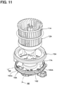
- FIG. 11 is an exploded view showing an electric motor, a centrifugal fan, and a bell mouth module in a comparative example.
- FIG. 12 is a sectional view taken along line XII-XII in FIG. 10 .
- FIG. 13 is a sectional view taken along the line XIII-XIII in FIG. 10 .
- FIG. 1 a blower unit according to an embodiment of the present disclosure will be described based on FIG. 1 , FIG. 2 , FIG. 3 , etc.
- a blower unit 1 of the present embodiment forms a vehicle air conditioner 4 together with an inside/outside air switching box 2 and an inside air conditioning unit 3 .
- the blower unit 1 is an air blowing unit which sucks in an airflow introduced from the inside/outside air switching box 2 and blows an airflow in two layers to the inside air conditioning unit 3 .
- the inside air conditioning unit 3 adjusts the temperature of the two layer airflow blown out from the blower unit 1 with a cooling heat exchanger, a heating heat exchanger, an air mixing door, etc., and blows out the two layer airflow into a passenger compartment.
- the inside/outside air switching box 2 introduces at least one of passenger compartment air (hereinafter referred to as “inside air”) and outside air (hereinafter referred to as “outside air”) to the blower unit 1 .
- the blower unit 1 includes a blower casing 10 , centrifugal fans 11 , 12 , scroll casings 13 , 14 , a bell mouth module 15 , an electric motor 16 , and a sealing material 17 .
- the blower casing 10 is formed with an opening portion 10 a which opens toward one side in the axial direction.
- the axial direction is the direction in which an axial line of a rotating shaft 16 a of the electric motor 16 extends.
- the opening portion 10 a forms an air suction port into which the airflow blown from the inside/outside air switching box 2 flows.
- a filter 10 c for removing impurities from the air blown from the inside/outside air switching box 2 is provided on the opening portion 10 a side of the blower casing 10 .
- the opening portion 10 a corresponds to a first opening portion.
- the blower casing 10 is formed with an opening portion 10 b which opens toward the other side in the axial direction.
- the opening portion 10 b is closed by the electric motor 16 .
- the opening portion 10 b corresponds to a second opening portion.
- the centrifugal fan 11 is a sirocco fan including a plurality of blades 11 a aligned along a circumferential direction about an axis line.
- the centrifugal fan 11 sucks air from one side in the axial direction and blows it outward in the radial direction.
- the radial direction refers to the radial direction about the axial line of the rotating shaft 16 a of the electric motor 16 .
- the centrifugal fan 11 corresponds to a first centrifugal fan.
- the centrifugal fan 12 is a sirocco fan including a plurality of blades 12 a aligned along a circumferential direction about an axis line.
- the centrifugal fan 12 is provided toward the other side in the axial direction with respect to the centrifugal fan 11 .
- the centrifugal fan 12 sucks air from the other side in the axial direction and blows it outward in the radial direction.
- the centrifugal fan 12 corresponds to a second centrifugal fan.
- the centrifugal fans 11 , 12 of the present embodiment are integrally formed from a resin material or the like.
- a boss portion 121 of the centrifugal fans 11 , 12 is connected to the rotation shaft 16 a of the electric motor 16 in the motor housing 160 .
- the scroll casing 13 is disposed toward one side in the axial direction inside the blower casing 10 .
- the scroll casing 13 accommodates the centrifugal fan 11 and forms an air intake port 13 a which opens toward one side in the axial direction.
- the scroll casing 13 corresponds to a first scroll casing.
- the air intake port 13 a corresponds to a first air intake port.
- a forming portion 13 b of the scroll casing 13 forms the air intake port 13 a .
- the forming portion 13 b forms a bell mouth portion that rectifies an airflow that flows from the opening portion 10 a of the blower casing 10 to the air intake port 13 a .
- the outer diameter dimension of the centrifugal fan 11 is larger than the inner diameter dimension of the opening portion of this bell mouth portion.
- the air intake port 13 a is formed such that the diameter dimension of the air intake port 13 a gradually increases toward one side in the axial direction.
- An air passage 13 c in the scroll casing 13 is provided radially outward of the centrifugal fan 11 .
- the air passage 13 c collects the air blown from the centrifugal fan 11 and blows out the air to the inside air conditioning unit 3 .
- the scroll casing 14 is disposed toward the other side in the axial direction inside the blower casing 10 .
- the scroll casing 14 accommodates the centrifugal fan 12 and forms an air intake port 14 a which opens toward the other side in the axial direction.
- An air passage 14 c in the scroll casing 14 is provided radially outward of the centrifugal fan 12 .
- the air passage 14 c collects the air blown from the centrifugal fan 12 and blows out the air to the inside air conditioning unit 3 .
- the scroll casing 14 corresponds to a second scroll casing.
- the air intake port 14 a corresponds to a second air intake port.
- the bell mouth module 15 includes a bell mouth portion 150 , leg portions 151 a to 151 c , an inner cylindrical portion 152 , a conical portion 153 , and support portions 154 a , 154 b , 154 c.
- the bell mouth portion 150 is formed annularly about the axial line so as to surround the air intake port 14 a .
- the bell mouth portion 150 is arranged toward the other side in the axial direction with respect to the air intake port 14 a of the scroll casing 14 .
- the bell mouth portion 150 is formed such that the diameter dimension of the air intake port 14 a gradually increases toward the other side in the axial direction.
- the bell mouth portion 150 rectifies the airflow flowing from the opening portion 10 a of the blower casing 10 through the air flow path 10 d to the air intake port 14 a .
- the outer diameter dimension of the centrifugal fan 12 is larger than the inner diameter dimension of the opening portion of the bell mouth portion 150 .
- the leg portions 151 a , 151 b , 151 c are formed so as to protrude from the bell mouth portion 150 toward the other side in the axial direction.
- the leg portions 151 a , 151 b , 151 c are arranged along the circumferential direction about the axial line.
- a claw portion 155 a is provided on the distal end side of the leg portion 151 a of the present embodiment.
- the claw portion 155 a is formed so as to protrude from the distal end side of the leg portion 151 a along a flange 162 of the electric motor 16 toward a bottom portion 162 b side of a recessed portion 162 a.
- Claw portions 155 b , 155 c are provided on the distal end sides of the leg portions 151 b , 151 c , respectively.
- the claw portions 155 b and 155 c are formed so as to protrude from the distal end sides of the leg portions 151 b and 151 c along the flange 162 of the electric motor 16 toward the bottom portion 162 b side of the recessed portion 162 a.
- the claw portions 155 a , 155 b , 155 c retain the sealing material 17 between the bottom portion 162 b of the recessed portion 162 a of the flange 162 of the electric motor 16 .
- the claw portion 155 a is disposed between an opening forming portion 100 of the blower casing 10 and the recessed portion 162 a of the flange 162 .
- the claw portions 155 b , 155 c are disposed between the opening forming portion 100 of the blower casing 10 and the recessed portion 162 a of the flange 162 .
- the leg portion 151 a and the claw portion 155 a of the present embodiment constitute a fixing portion for retaining the sealing material 17 .
- the leg portion 151 b and the claw portion 155 b constitute a fixing portion for retaining the sealing material 17 .
- the leg portion 151 c and the claw portion 155 c constitute a fixing portion for retaining the sealing material 17 .
- the leg portions 151 a , 151 b , 151 c and the claw portions 155 a , 155 b , 155 c correspond to a retaining portion.
- leg portion 151 a and the claw portion 155 a are disposed so as to not be in contact with the motor housing 160 of the electric motor 16 .
- the leg portion 151 b and the claw portion 155 b are disposed so as to not be in contact with the motor housing 160 of the electric motor 16 .
- the leg portion 151 c and the claw portion 155 c are disposed so as to not be in contact with the motor housing 160 of the electric motor 16 .
- the inner cylindrical portion 152 is formed in a cylindrical shape that surrounds an annular protrusion portion 163 of the motor housing 160 from the radially outer side.
- the inner cylindrical portion 152 forms a supported portion that is fitted with the annular protrusion portion 163 of the motor housing 160 and is supported by the motor housing 160 of the electric motor.
- the conical portion 153 surrounds a portion of the inner cylindrical portion 152 toward the other side in the axial direction from the radially outer side, and is formed in a conical shape with a diameter dimension centered on the axial line that increases toward the one side in the axial direction.
- the conical portion 153 faces a main plate 122 of the centrifugal fans 11 , 12 with a space between the conical portion 153 and the main plate 122 .
- a throughhole 152 b penetrating in the radial direction is provided on the other side of the inner cylindrical portion 152 in the axial direction.
- Support portions 154 a , 154 b , 154 c serve to improve rigidity by connecting the inner cylindrical portion 152 and the conical portion 153 to the leg portions 151 a to 151 c.
- the electric motor 16 includes the motor housing 160 and a motor main body 160 a .
- the motor housing 160 houses the motor main body 160 a .
- the motor main body 160 a is composed of a rotor, a stator, etc., and is disposed within the annular protrusion portion 163 of the motor housing 160 .
- the motor housing 160 includes a housing main body 161 , the flange 162 , and the annular protrusion portion 163 .
- the housing main body 161 is formed in a cylindrical shape about the axial line as the center.
- the flange 162 is formed in an annular shape surrounding the portion of the housing main body 161 toward the other end of the axial direction from the radially outer side.
- a recessed portion 162 a is provided on the radially outer side of the flange 162 of the present embodiment.
- the recessed portion 162 a is recessed toward the other side in the axial direction and is formed in an annular shape about the axial line.
- the recessed portion 162 a accommodates the sealing material 17 .
- the sealing material 17 is made of an elastic material such as rubber, and is formed in an annular shape about the axial line.
- the flange 162 includes three protruding portions 164 .
- Each of the three protruding portions 164 protrudes toward the one side in the axial direction and is formed into a U shape surrounding the leg portions 151 a , 151 b , 151 c .
- Each of the three protruding portions 164 defines the position of a corresponding leg portion of the leg portions 151 a , 151 b , and 151 c.
- the sealing material 17 forms a seal between the opening forming portion 100 of the blower casing 10 that forms the opening portion 10 b and the bottom portion 162 b of the recessed portion 162 a of the flange 162 .
- the sealing material 17 is in an elastically deformed state as will be described later.
- the annular protrusion portion 163 protrudes from one side of the housing main body 161 in the axial direction toward the one side in the axial direction and is formed in a cylindrical shape.
- a claw portion 163 a which protrudes radially outward is formed.
- one side of the annular protrusion portion 163 in the axial direction is fitted in the inner cylindrical portion 152 , and in this state, the claw portion 163 a is fitted into the throughhole 152 b of the inner cylindrical portion 152 .
- the claw portion 163 a serves a role of fixing the bell mouth module 15 to the electric motor 16 .
- the inside/outside air switching box 2 includes a housing 200 and inside/outside air switching doors 201 , 202 .
- the housing 200 forms an outside air introduction port 203 and an inside air introduction port 204 .
- the outside air introduction port 203 introduces outside air from outside of the passenger compartment into the housing 200 through an outside air introduction duct 210 .
- the inside air introduction port 204 introduces inside air into the housing 200 from inside the passenger compartment.
- the inside/outside air switching door 201 opens and closes the outside air introduction port 203 .
- the inside/outside air switching door 202 opens and closes the inside air introduction port 204 .
- the inside/outside air switching doors 201 , 202 are driven to open or close by a servomotor. As a result, at least one of outside air from the outside air introduction port 203 and inside air from the inside air introduction port 204 can be introduced into the opening portion 10 a of the blower casing 10 .
- the element denoted by reference numeral 300 in FIG. 6 is a connector for connecting the electric motor 16 to an electronic control unit.
- blower unit 1 of the present embodiment will be described with reference to FIG. 2 etc.
- the electric motor 16 outputs a rotational force from the rotating shaft 16 a to the centrifugal fans 11 , 12 . Accordingly, the centrifugal fans 11 and 12 are rotationally driven by the rotating shaft 16 a to rotate.
- the centrifugal fan 11 rotates, the air blown out from the inside/outside air switching box 2 is sucked through the filter 10 c .
- the forming portion 13 b rectifies the air sucked in from the inside/outside air switching box 2 through the filter 10 c and guides the air to the centrifugal fan 11 .
- the centrifugal fan 11 blows air outward in the radial direction.
- the blown air is collected in the air passage 13 c of the scroll casing 13 and blown out to the inside air conditioning unit 3 .
- the centrifugal fan 12 rotates, air is sucked in from the inside/outside air switching box 2 through the filter 10 c and the air flow path 10 d .
- the bell mouth portion 150 rectifies the air sucked in from the inside/outside air switching box 2 through the filter 10 c and the air flow path 10 d and guides the air to the centrifugal fan 12 .
- the centrifugal fan 12 blows air outward in the radial direction of the axial line.
- the blown air is collected in the air passage 14 c of the scroll casing 14 and blown out to the inside air conditioning unit 3 .
- the inside air conditioning unit 3 adjusts the temperature of the two layers of air blown out from the blower unit 1 in this manner and blows the air into the passenger compartment.
- the assembly of the blower unit 1 of the present embodiment will be described with reference to FIG. 9 .
- the subject that performs this assembly is referred to as the performing subject.
- This performing subject may be a person or an assembling apparatus. Further, the performing subject may be a combination of a person in one setting and an assembling apparatus in another setting.
- step S 100 which is an initial preparation step, the performing subject separately prepares the electric motor 16 , the centrifugal fans 11 , 12 , the bell mouth module 15 , and the sealing material 17 .
- the performing subject prepares the blower casing 10 and the scroll casings 13 , 14 in a state where the scroll casings 13 , 14 are accommodated in the blower casing 10 .
- the performing subject houses the sealing material 17 in the recessed portion 162 a of the flange 162 of the electric motor 16 .
- the performing subject also inserts the annular protrusion portion 163 of the motor housing 160 of the electric motor 16 into the inner cylindrical portion 152 of the bell mouth module 15 from the other side in the axial direction.
- the claw portion 163 a of the annular protrusion portion 163 of the motor housing 160 of the electric motor 16 fits into the throughhole 152 b of the inner cylindrical portion 152 of the bell mouth module 15 as shown in FIG. 5 .
- the bell mouth module 15 is fixed to the motor housing 160 of the electric motor 16 .
- the sealing material 17 is interposed between the claw portions 155 a , 155 b , 155 c of the bell mouth module 15 and the bottom portion 162 b of the recessed portion 162 a of the flange 162 of the electric motor 16 .
- the sealing material 17 is retained by the claw portions 155 a , 155 b , 155 c of the bell mouth module 15 and the bottom portion 162 b of the recessed portion 162 a of the flange 162 of the electric motor 16 .
- the bell mouth module 15 As a result, the bell mouth module 15 , the electric motor 16 , and the sealing material 17 are assembled into one unit.
- the performing subject arranges the centrifugal fans 11 and 12 on the lower side of the bell mouth module 15 , the electric motor 16 , and the sealing material 17 in the top-down direction. Along with this, the performing subject inserts the boss portion 121 of the centrifugal fans 11 , 12 into the inner cylindrical portion 152 of the bell mouth module 15 . As a result, the boss portion 121 of the centrifugal fans 11 , 12 is connected to the rotation shaft 16 a in the annular protrusion portion 163 of the motor housing 160 .
- step 130 the performing subject assembles the bell mouth module 15 , the electric motor 16 , and the sealing material 17 with respect to the blower casing 10 .
- the performing subject inserts the centrifugal fans 11 , 12 into the scroll casings 13 , 14 , and closes the opening portion 10 b of the blower casing 10 with the motor housing 160 of the electric motor 16 .
- the performing subject also fixes the blower casing 10 to the motor housing 160 with a fastening member or the like.
- the sealing material 17 is compressed by elastic deformation between the opening forming portion 100 of the blower casing 10 and the bottom portion 162 b of the recessed portion 162 a of the flange 162 of the electric motor 16 .
- the sealing material 17 is able to form a seal between the opening forming portion 100 of the blower casing 10 and the bottom portion 162 b of the recessed portion 162 a of the flange 162 of the electric motor 16 .
- the blower unit 1 configured as described above exhibits advantages when rainwater or the like enters the electric motor 16 side of the blower casing 10 from outside of the vehicle through the outside air introduction duct 210 and the inside/outside air switching box 2 . Specifically, at this time, rainwater or the like is prevented from leaking into the passenger compartment through the gap between the opening forming portion 100 of the blower casing 10 and the bottom portion 162 b of the recessed portion 162 a of the electric motor 16 .
- blower unit of a comparative example which includes a blower case, first and second centrifugal fans, first and second scroll cases, and an electric motor.
- the comparative example blower unit is defined to have the below features.
- a first opening portion is provided, through which air flow is introduced from an inside/outside air switching introduction box.
- the first centrifugal fan is housed in the blower case and is disposed on one side of the electric motor in the axial direction.
- the first centrifugal fan is driven by the electric motor to rotate, thereby sucking in air from one side in the axial direction and blowing the air out radially outward.
- the second centrifugal fan is housed in the blower case and is disposed between the first centrifugal fan and the electric motor.
- the second centrifugal fan is driven by the electric motor to rotate, thereby sucking in air from the other side in the axial direction and blowing the air out radially outward.
- the blower case is provided with an opening forming portion that forms a second opening portion.
- the second opening portion opens toward the other side in the axial direction.
- the second opening is closed by the electric motor.
- the first and second scroll casings for housing the first and second centrifugal fans are housed in the blower case.
- a first air suction portion and a first air flow path are formed in the first scroll casing.
- the first air suction port opens to one side in the axial direction and guides the air from the first opening portion to the first centrifugal fan.
- the first air flow path collects the air blown out from the first centrifugal fan and blows out the collected air.
- a second air suction portion and a second air flow path are formed in the second scroll casing.
- the second air suction port opens to the other side in the axial direction and guides the air from the first opening portion to the second centrifugal fan.
- the second air flow path collects the air blown out from the second centrifugal fan and blows out the collected air.
- rainwater or the like may enter the inside of the blower case from outside the vehicle compartment through an outside air introduction hole of the inside/outside air switching introduction box.
- the blower case is disposed in the passenger compartment.
- a sealing material may be provided between the opening forming portion of the blower case and the electric motor.
- first and second bell mouth portions are used for rectifying and guiding the air from the first opening portion to the first and second air intake ports.
- the outer diameters of the first and second centrifugal fans are larger than the inner diameters of the opening portions of the first and second bell mouth portions. Therefore, by using first and second bell mouth portions which are integrally formed with the first and second scroll casings, it is not possible to insert the first and second centrifugal fans in the first and second scroll casings.
- a member molded integrally with the first scroll casing may be used as the first bell mouth portion, and a member molded independently from the second scroll casing may be used as the second bell mouth portion.
- FIG. 10 and FIG. 11 which illustrate another comparative example, the present inventor examined the possibility of assembling the first and second centrifugal fans 11 A, 12 A, the electric motor 16 A, the second bell mouth portion 15 A, and the sealing material 17 A.
- the second bell mouth portion 15 A is fastened to the electric motor 16 A, and the first and second centrifugal fans are arranged on the lower side of the electric motor 16 A in the top-down direction. Then, the rotating shaft of the electric motor 16 A is connected to the first and second centrifugal fans 11 A, 12 A, and the electric motor 16 A, the first and second centrifugal fans 11 A, 12 A, and the second bell mouth portion 15 A are assembled into a single unit. The integrated electric motor 16 A, the first and second centrifugal fans 11 A and 12 A, and the second bell mouth portion 15 A are assembled into the blower case.
- the flange 162 of the motor housing 160 A of the electric motor 16 A is provided with a recessed portion 162 a for accommodating the sealing material 17 A, and the side wall of the recessed portion 162 a is provided with a claw portion 165 which protrudes radially outwardly.
- the claw portion 165 can hold the sealing material 17 A in the recessed portion 162 a.
- the manufacturing method of the blower unit 1 of the present embodiment includes the step of preparing the bell mouth module 15 , the electric motor 16 , and the sealing material 17 . Further, in this manufacturing method, the sealing material 17 is interposed between the claw portions 155 a to 155 c of the bell mouth module 15 and the bottom portion 162 b of the recessed portion 162 a of the flange 162 of the electric motor 16 , and the bell mouth module 15 is attached to the electric motor 16 .
- the manufacturing method of the blower unit 1 includes a step of connecting the centrifugal fan 11 and the centrifugal fan 12 to the rotating shaft 16 a of the electric motor 16 in a state where the bell mouth module 15 is attached to the electric motor 16 . Furthermore, this manufacturing method includes a step of attaching the electric motor 16 to the blower casing 10 in a particular state. In the particular state, the centrifugal fan 11 is housed in the scroll casing 13 , the centrifugal fan 12 is housed in the scroll casing 14 , and the opening portion 10 b of the blower casing 10 is closed by the electric motor 16 .
- the rotating shaft 16 a of the electric motor 16 may be coupled to the centrifugal fans 11 , 12 in a state where the sealing material 17 is interposed between the claw portions 155 a to 155 c of the bell mouth module 15 and the bottom portion 162 b of the recessed portion 162 a of the flange 162 of the electric motor 16 .
- blower unit 1 Due to the above, it is possible to provide the blower unit 1 with improved manufacturability and a blower unit 1 manufacturing method suitable for this blower unit 1 .
- the bell mouth module 15 has a structure in which the claw portions 155 a to 155 c are provided on the leg portions 151 a to 151 c . For this reason, unlike the flange 162 of the electric motor 16 A in FIG. 11 , there is no need to provide the claw portion 165 and the hole 166 , so that metal molds with simple structures may be used.
- the leg portions 151 a to 151 c and the claw portions 155 a to 155 c of the bell mouth module 15 are disposed so as to be out of contact with the motor housing 160 of the electric motor 16 . For this reason, vibrations and noises of the electric motor 16 may be prevented from being transmitted to the vehicle interior through the bell mouth module 15 , the centrifugal fans 11 , 12 , and the inside air conditioning unit 3 .
- the flange 162 of the motor housing 160 is provided with the recessed portion 162 a that accommodates the sealing material 17 . Therefore, the sealing material 17 may be easily retained by the motor housing 160 of the electric motor 16 and the bell mouth module 15 .
- blower unit 1 is applied to a vehicle, but the blower unit 1 may be applied to things other than a vehicle (for example, stationary air conditioners).
- a quantity, a value, an amount, a range, or the like, if specified in the above-described example embodiments, is not necessarily limited to the specific value, amount, range, or the like unless it is specifically stated that the value, amount, range, or the like is necessarily the specific value, amount, range, or the like, or unless the value, amount, range, or the like is obviously necessary to be the specific value, amount, range, or the like in principle.
- a material, a shape, a positional relationship, or the like if specified in the above-described example embodiments, is not necessarily limited to the specific shape, positional relationship, or the like unless it is specifically stated that the material, shape, positional relationship, or the like is necessarily the specific material, shape, positional relationship, or the like, or unless the shape, positional relationship, or the like is obviously necessary to be the specific shape, positional relationship, or the like in principle.
- an electric motor that includes a rotating shaft which outputs a rotational force
- a first centrifugal fan disposed on one side of the electric motor in an axial direction of the rotating shaft, the first centrifugal fan configured to be rotated by the rotational force of the rotating shaft to suck in air from the one side in the axial direction and blowing out the air outward in a radial direction centered about an axial line of the rotating shaft,
- a second centrifugal fan disposed between the first centrifugal fan and the electric motor, the second centrifugal fan configured to be rotated by the rotational force of the rotating shaft to suck in air from an other side in the axial direction and blowing out the air outward in the radial direction centered about the axial line of the rotating shaft,
- blower casing that forms a first opening portion into which air flows, the blower casing including an opening forming portion that forms a second opening portion that opens toward the other side in the axial direction,
- a first scroll casing which is disposed inside the blower casing and which houses the first centrifugal fan, the first scroll casing forming a first air intake port that opens toward the one side in the axial direction and that guides the air from the first opening portion to the first centrifugal fan, the air blown out from the first centrifugal fan being blown out by the first scroll casing,
- a second scroll casing which is disposed inside the blower casing and which houses the second centrifugal fan, the second scroll casing forming a second air intake port that opens toward the other side in the axial direction, the air blown out from the second centrifugal fan being blown out by the second scroll casing,
- a bell mouth module that includes a bell mouth portion which is disposed within the blower casing and which rectifies an air flow from the first opening portion and guides the air flow to the second centrifugal fan through the second air intake port, and a retaining portion that retains the sealing material, the manufacturing method includes
- closing the second opening portion of the blower casing by: housing the first centrifugal fan in the first scroll casing, housing the second centrifugal fan in the second scroll casing, and attaching the electric motor to the blower casing.
- a blower unit includes
- an electric motor that includes a rotating shaft which outputs a rotational force
- a first centrifugal fan disposed on one side of the electric motor in an axial direction of the rotating shaft, the first centrifugal fan configured to be rotated by the rotational force of the rotating shaft to suck in air from the one side in the axial direction and blowing out the air outward in a radial direction centered about an axial line of the rotating shaft,
- a second centrifugal fan disposed between the first centrifugal fan and the electric motor, the second centrifugal fan configured to be rotated by the rotational force of the rotating shaft to suck in air from an other side in the axial direction and blowing out the air outward in the radial direction centered about the axial line, and
- blower casing that forms a first opening portion into which air flows, the blower casing including an opening forming portion that forms a second opening portion that opens toward the other side in the axial direction, wherein
- the electric motor is disposed such that the second opening portion of the blower casing is closed by the electric motor
- the blower unit further includes
- first scroll casing disposed inside the blower casing that houses the first centrifugal fan, the first scroll casing forming a first air intake port that opens toward the one side in the axial direction and that guides the air from the first opening portion to the first centrifugal fan, the air blown out from the first centrifugal fan being blown out by the first scroll casing,
- a second scroll casing disposed inside the blower casing that houses the second centrifugal fan, the second scroll casing forming a second air intake port that opens toward the other side in the axial direction, the air blown out from the second centrifugal fan being blown out by the second scroll casing,
- the bell mouth module disposed within the blower casing and supported by the electric motor, the bell mouth module including a bell mouth portion which rectifies an air flow from the first opening portion and guides the air flow to the second centrifugal fan through the second air intake port, wherein
- the bell mouth module includes a retaining portion that, together with the electric motor, retains the sealing material by interposing the sealing material between the bell mouth module and the electric motor.
- the electric motor forms a recessed portion that is recessed toward the other side in the axial direction and accommodates the sealing material.
- the bell mouth module is disposed such that the retaining portion of the bell mouth module is not in contact with the electric motor.
Landscapes
- Engineering & Computer Science (AREA)
- Mechanical Engineering (AREA)
- General Engineering & Computer Science (AREA)
- Physics & Mathematics (AREA)
- Thermal Sciences (AREA)
- Structures Of Non-Positive Displacement Pumps (AREA)
- Air-Conditioning For Vehicles (AREA)
Abstract
Description
Claims (10)
Applications Claiming Priority (4)
| Application Number | Priority Date | Filing Date | Title |
|---|---|---|---|
| JPJP2016-107666 | 2016-05-30 | ||
| JP2016-107666 | 2016-05-30 | ||
| JP2016107666 | 2016-05-30 | ||
| PCT/JP2017/015852 WO2017208657A1 (en) | 2016-05-30 | 2017-04-20 | Blower unit and method for manufacturing blower unit |
Related Parent Applications (1)
| Application Number | Title | Priority Date | Filing Date |
|---|---|---|---|
| PCT/JP2017/015852 Continuation WO2017208657A1 (en) | 2016-05-30 | 2017-04-20 | Blower unit and method for manufacturing blower unit |
Publications (2)
| Publication Number | Publication Date |
|---|---|
| US20190092128A1 US20190092128A1 (en) | 2019-03-28 |
| US11279207B2 true US11279207B2 (en) | 2022-03-22 |
Family
ID=60478280
Family Applications (1)
| Application Number | Title | Priority Date | Filing Date |
|---|---|---|---|
| US16/200,701 Active 2037-10-19 US11279207B2 (en) | 2016-05-30 | 2018-11-27 | Blower unit, and method of manufacturing blower unit |
Country Status (5)
| Country | Link |
|---|---|
| US (1) | US11279207B2 (en) |
| EP (1) | EP3467322B1 (en) |
| JP (1) | JP6521180B2 (en) |
| CN (1) | CN109196231B (en) |
| WO (1) | WO2017208657A1 (en) |
Families Citing this family (6)
| Publication number | Priority date | Publication date | Assignee | Title |
|---|---|---|---|---|
| JP2018167638A (en) * | 2017-03-29 | 2018-11-01 | 株式会社日本クライメイトシステムズ | Ventilator for vehicle air conditioning |
| KR102536611B1 (en) * | 2017-05-22 | 2023-05-25 | 한온시스템 주식회사 | Blower unit of two layer type air conditioner for vehicle |
| JP6966369B2 (en) * | 2018-03-27 | 2021-11-17 | 株式会社日本クライメイトシステムズ | Blower for vehicle air conditioning |
| JP7036645B2 (en) * | 2018-03-27 | 2022-03-15 | 株式会社日本クライメイトシステムズ | Blower for vehicle air conditioning |
| JP7575860B2 (en) * | 2018-11-28 | 2024-10-30 | 株式会社日本クライメイトシステムズ | Vehicle air conditioning blower |
| KR102707338B1 (en) * | 2019-09-11 | 2024-09-20 | 한온시스템 주식회사 | Blower unit for vehicle and air conditioner having the same |
Citations (4)
| Publication number | Priority date | Publication date | Assignee | Title |
|---|---|---|---|---|
| US7682233B2 (en) * | 2005-06-17 | 2010-03-23 | Halla Climate Control Corporation | Blower for air conditioner of automotive vehicles |
| US20120207593A1 (en) * | 2011-02-14 | 2012-08-16 | Denso Corporation | Blower unit |
| WO2012144153A1 (en) | 2011-04-19 | 2012-10-26 | 株式会社デンソー | Air-conditioning device for vehicle |
| US20150167688A1 (en) * | 2013-12-13 | 2015-06-18 | New Motech Co., Ltd. | Fan motor |
Family Cites Families (5)
| Publication number | Priority date | Publication date | Assignee | Title |
|---|---|---|---|---|
| US6406275B1 (en) * | 2000-09-22 | 2002-06-18 | Delphi Technologies, Inc. | Cut for service motor with service ring |
| AU2003284610B2 (en) * | 2002-12-16 | 2006-11-16 | Daikin Industries, Ltd. | Centrifugal fan, and air conditioner provided therewith |
| JPWO2008093390A1 (en) * | 2007-01-29 | 2010-05-20 | 三菱電機株式会社 | Multi-blade centrifugal blower |
| FR2961971B1 (en) * | 2010-06-24 | 2012-08-10 | Valeo Systemes Thermiques | MOTOR SUPPORT WITH MOVEMENT LIMITATION DEVICE |
| WO2012164878A1 (en) * | 2011-06-03 | 2012-12-06 | 株式会社デンソー | Blower |
-
2017
- 2017-04-20 CN CN201780033029.1A patent/CN109196231B/en not_active Expired - Fee Related
- 2017-04-20 EP EP17806217.0A patent/EP3467322B1/en active Active
- 2017-04-20 WO PCT/JP2017/015852 patent/WO2017208657A1/en not_active Ceased
- 2017-04-20 JP JP2018520709A patent/JP6521180B2/en not_active Expired - Fee Related
-
2018
- 2018-11-27 US US16/200,701 patent/US11279207B2/en active Active
Patent Citations (6)
| Publication number | Priority date | Publication date | Assignee | Title |
|---|---|---|---|---|
| US7682233B2 (en) * | 2005-06-17 | 2010-03-23 | Halla Climate Control Corporation | Blower for air conditioner of automotive vehicles |
| US20120207593A1 (en) * | 2011-02-14 | 2012-08-16 | Denso Corporation | Blower unit |
| WO2012144153A1 (en) | 2011-04-19 | 2012-10-26 | 株式会社デンソー | Air-conditioning device for vehicle |
| US20140045417A1 (en) | 2011-04-19 | 2014-02-13 | Toyota Jidosha Kabushiki Kaisha | Air-conditioner for vehicle |
| US9643472B2 (en) * | 2011-04-19 | 2017-05-09 | Toyota Jidosha Kabushiki Kaisha | Air-conditioner for vehicle |
| US20150167688A1 (en) * | 2013-12-13 | 2015-06-18 | New Motech Co., Ltd. | Fan motor |
Also Published As
| Publication number | Publication date |
|---|---|
| EP3467322B1 (en) | 2020-04-01 |
| CN109196231B (en) | 2020-05-05 |
| US20190092128A1 (en) | 2019-03-28 |
| CN109196231A (en) | 2019-01-11 |
| EP3467322A4 (en) | 2019-06-19 |
| JP6521180B2 (en) | 2019-05-29 |
| JPWO2017208657A1 (en) | 2018-09-13 |
| EP3467322A1 (en) | 2019-04-10 |
| WO2017208657A1 (en) | 2017-12-07 |
Similar Documents
| Publication | Publication Date | Title |
|---|---|---|
| US11279207B2 (en) | Blower unit, and method of manufacturing blower unit | |
| US7118355B2 (en) | Electric motor driven blower assembly with integral motor cooling duct | |
| JP4488075B2 (en) | Electric blower | |
| JP2003301794A (en) | Centrifugal blower | |
| WO2015004836A1 (en) | Blower | |
| US11499568B2 (en) | Centrifugal fan and centrifugal blower | |
| JP3498347B2 (en) | Blower | |
| JP2012505990A (en) | Vehicle fan device | |
| JP5304719B2 (en) | Ventilation unit for vehicle air conditioner | |
| CN112204855A (en) | Electric blower | |
| US20060103245A1 (en) | Engine cooling motor-module ventilation configuration | |
| WO2018180980A1 (en) | Vehicle air-conditioner blowing apparatus | |
| JP2022183794A (en) | Blower for vehicular air conditioner | |
| TWI529305B (en) | Ventilator | |
| JP2018001820A (en) | Blower unit | |
| JP2003080922A (en) | Motor installing structure | |
| CN118489036A (en) | Centrifugal fan | |
| JP7052691B2 (en) | Centrifugal blower, manufacturing method of centrifugal blower | |
| US20260039166A1 (en) | Blower motor for vehicles | |
| CN114630964B (en) | Blower | |
| WO2019003786A1 (en) | Centrifugal blower | |
| WO2024009353A1 (en) | Centrifugal blower and ventilation fan | |
| JPH09295505A (en) | Intake unit of vehicle air conditioner | |
| JP2022183797A (en) | Blower for vehicular air conditioner | |
| WO2020095563A1 (en) | Centrifugal blower |
Legal Events
| Date | Code | Title | Description |
|---|---|---|---|
| AS | Assignment |
Owner name: DENSO CORPORATION, JAPAN Free format text: ASSIGNMENT OF ASSIGNORS INTEREST;ASSIGNOR:KAMIYA, TOMOHIRO;REEL/FRAME:047586/0636 Effective date: 20181023 |
|
| FEPP | Fee payment procedure |
Free format text: ENTITY STATUS SET TO UNDISCOUNTED (ORIGINAL EVENT CODE: BIG.); ENTITY STATUS OF PATENT OWNER: LARGE ENTITY |
|
| STPP | Information on status: patent application and granting procedure in general |
Free format text: APPLICATION DISPATCHED FROM PREEXAM, NOT YET DOCKETED |
|
| STPP | Information on status: patent application and granting procedure in general |
Free format text: DOCKETED NEW CASE - READY FOR EXAMINATION |
|
| STPP | Information on status: patent application and granting procedure in general |
Free format text: NON FINAL ACTION MAILED |
|
| STPP | Information on status: patent application and granting procedure in general |
Free format text: DOCKETED NEW CASE - READY FOR EXAMINATION |
|
| STPP | Information on status: patent application and granting procedure in general |
Free format text: NON FINAL ACTION MAILED |
|
| STPP | Information on status: patent application and granting procedure in general |
Free format text: RESPONSE TO NON-FINAL OFFICE ACTION ENTERED AND FORWARDED TO EXAMINER |
|
| STPP | Information on status: patent application and granting procedure in general |
Free format text: NOTICE OF ALLOWANCE MAILED -- APPLICATION RECEIVED IN OFFICE OF PUBLICATIONS |
|
| STCF | Information on status: patent grant |
Free format text: PATENTED CASE |
|
| MAFP | Maintenance fee payment |
Free format text: PAYMENT OF MAINTENANCE FEE, 4TH YEAR, LARGE ENTITY (ORIGINAL EVENT CODE: M1551); ENTITY STATUS OF PATENT OWNER: LARGE ENTITY Year of fee payment: 4 |