US11273513B2 - Coupling device - Google Patents

Coupling device Download PDF

Info

Publication number
US11273513B2
US11273513B2 US16/286,603 US201916286603A US11273513B2 US 11273513 B2 US11273513 B2 US 11273513B2 US 201916286603 A US201916286603 A US 201916286603A US 11273513 B2 US11273513 B2 US 11273513B2
Authority
US
United States
Prior art keywords
plate
coupling member
pilot portion
electrode
coupling
Prior art date
Legal status (The legal status is an assumption and is not a legal conclusion. Google has not performed a legal analysis and makes no representation as to the accuracy of the status listed.)
Active, expires
Application number
US16/286,603
Other versions
US20190193189A1 (en
Inventor
Rikiya Nishimura
Etsuo MASUNAGA
Current Assignee (The listed assignees may be inaccurate. Google has not performed a legal analysis and makes no representation or warranty as to the accuracy of the list.)
Shinko Holdings Co Ltd
Shinjo Holdings Co Ltd
Original Assignee
Shinko Holdings Co Ltd
Priority date (The priority date is an assumption and is not a legal conclusion. Google has not performed a legal analysis and makes no representation as to the accuracy of the date listed.)
Filing date
Publication date
Application filed by Shinko Holdings Co Ltd filed Critical Shinko Holdings Co Ltd
Assigned to SHINJO HOLDINGS CO., LTD. reassignment SHINJO HOLDINGS CO., LTD. ASSIGNMENT OF ASSIGNORS INTEREST (SEE DOCUMENT FOR DETAILS). Assignors: NISHIMURA, RIKIYA, MASUNAGA, ETSUO
Publication of US20190193189A1 publication Critical patent/US20190193189A1/en
Application granted granted Critical
Publication of US11273513B2 publication Critical patent/US11273513B2/en
Active legal-status Critical Current
Adjusted expiration legal-status Critical

Links

Images

Classifications

    • BPERFORMING OPERATIONS; TRANSPORTING
    • B23MACHINE TOOLS; METAL-WORKING NOT OTHERWISE PROVIDED FOR
    • B23KSOLDERING OR UNSOLDERING; WELDING; CLADDING OR PLATING BY SOLDERING OR WELDING; CUTTING BY APPLYING HEAT LOCALLY, e.g. FLAME CUTTING; WORKING BY LASER BEAM
    • B23K11/00Resistance welding; Severing by resistance heating
    • B23K11/16Resistance welding; Severing by resistance heating taking account of the properties of the material to be welded
    • B23K11/20Resistance welding; Severing by resistance heating taking account of the properties of the material to be welded of different metals
    • BPERFORMING OPERATIONS; TRANSPORTING
    • B21MECHANICAL METAL-WORKING WITHOUT ESSENTIALLY REMOVING MATERIAL; PUNCHING METAL
    • B21JFORGING; HAMMERING; PRESSING METAL; RIVETING; FORGE FURNACES
    • B21J15/00Riveting
    • BPERFORMING OPERATIONS; TRANSPORTING
    • B23MACHINE TOOLS; METAL-WORKING NOT OTHERWISE PROVIDED FOR
    • B23KSOLDERING OR UNSOLDERING; WELDING; CLADDING OR PLATING BY SOLDERING OR WELDING; CUTTING BY APPLYING HEAT LOCALLY, e.g. FLAME CUTTING; WORKING BY LASER BEAM
    • B23K11/00Resistance welding; Severing by resistance heating
    • B23K11/002Resistance welding; Severing by resistance heating specially adapted for particular articles or work
    • B23K11/004Welding of a small piece to a great or broad piece
    • B23K11/0066Riveting
    • BPERFORMING OPERATIONS; TRANSPORTING
    • B23MACHINE TOOLS; METAL-WORKING NOT OTHERWISE PROVIDED FOR
    • B23KSOLDERING OR UNSOLDERING; WELDING; CLADDING OR PLATING BY SOLDERING OR WELDING; CUTTING BY APPLYING HEAT LOCALLY, e.g. FLAME CUTTING; WORKING BY LASER BEAM
    • B23K11/00Resistance welding; Severing by resistance heating
    • B23K11/10Spot welding; Stitch welding
    • B23K11/11Spot welding
    • B23K11/115Spot welding by means of two electrodes placed opposite one another on both sides of the welded parts
    • BPERFORMING OPERATIONS; TRANSPORTING
    • B23MACHINE TOOLS; METAL-WORKING NOT OTHERWISE PROVIDED FOR
    • B23KSOLDERING OR UNSOLDERING; WELDING; CLADDING OR PLATING BY SOLDERING OR WELDING; CUTTING BY APPLYING HEAT LOCALLY, e.g. FLAME CUTTING; WORKING BY LASER BEAM
    • B23K2103/00Materials to be soldered, welded or cut
    • B23K2103/02Iron or ferrous alloys
    • BPERFORMING OPERATIONS; TRANSPORTING
    • B23MACHINE TOOLS; METAL-WORKING NOT OTHERWISE PROVIDED FOR
    • B23KSOLDERING OR UNSOLDERING; WELDING; CLADDING OR PLATING BY SOLDERING OR WELDING; CUTTING BY APPLYING HEAT LOCALLY, e.g. FLAME CUTTING; WORKING BY LASER BEAM
    • B23K2103/00Materials to be soldered, welded or cut
    • B23K2103/08Non-ferrous metals or alloys
    • B23K2103/10Aluminium or alloys thereof
    • BPERFORMING OPERATIONS; TRANSPORTING
    • B23MACHINE TOOLS; METAL-WORKING NOT OTHERWISE PROVIDED FOR
    • B23KSOLDERING OR UNSOLDERING; WELDING; CLADDING OR PLATING BY SOLDERING OR WELDING; CUTTING BY APPLYING HEAT LOCALLY, e.g. FLAME CUTTING; WORKING BY LASER BEAM
    • B23K2103/00Materials to be soldered, welded or cut
    • B23K2103/18Dissimilar materials
    • B23K2103/20Ferrous alloys and aluminium or alloys thereof

Definitions

  • the present invention relates to a coupling device.
  • JP 08-033987A includes pressurizing and electrifying, using electrodes, an iron plate, an aluminum plate, and an engagement piece with these plates and piece arranged in this order from top. This causes a portion of the aluminum plate contacting the engagement piece to melt, allowing the engagement piece to penetrate the aluminum plate. Then, the iron plate and the leading end of the engagement piece are subjected to resistance welding. Thus, the engagement piece is used as a coupling member to couple (fasten) the iron plate and the aluminum plate to each other.
  • a coupling device is configured to, using a coupling member, couple a first plate made of a first metal and a second plate made of a second metal to each other.
  • the coupling device includes a first electrode, a second electrode, a power source, a driver, and a controller.
  • the power source is connected to the first electrode and the second electrode.
  • the driver is configured to move the first electrode and the second electrode relative to the coupling member, the first plate, and the second plate.
  • the controller is configured to control the power source and the driver to electrify the coupling member, the first plate, and the second plate while controlling the first electrode and the second electrode to apply pressure to the coupling member, the first plate, and the second plate.
  • the coupling member is made of a third metal approximately identical to the second metal.
  • the first metal has a melting point lower than a melting point of the second metal and a melting point of the third metal.
  • the coupling member includes a body and a pilot portion.
  • the pilot portion is provided approximately at a center of a flat surface of the body and protrudes in an extending direction. On the flat surface, a plurality of discharge grooves are formed radially extending from the pilot portion.
  • the controller is configured to make the coupling member, the first plate, and the second plate held between the first plate and the second plate so as to make a contact state between: a leading end of the first electrode and the body of the coupling member; the pilot portion of the coupling member and a first main surface of the first plate; a second main surface of the first plate and a first main surface of the second plate; and a second main surface of the second plate and a leading end of the second electrode.
  • the controller is configured to, while maintaining the contact state, control the power source to electrify the coupling member, the first plate, and the second plate while controlling the driver to apply pressure to the coupling member, the first plate, and the second plate so as to: melt a facing portion of the first plate facing the pilot portion of the coupling member, and remove the melted facing portion to a farther side of the pilot portion through the plurality of discharge grooves formed on the coupling member, whereby the facing portion is removed, allowing a leading end of the pilot portion and a joint portion of the second plate to contact each other; and melt and solidify the leading end of the pilot portion and the joint portion of the second plate to couple the leading end of the pilot portion and the joint portion of the second plate to each other.
  • a coupling device is configured to, using a coupling member, couple a first plate made of a first metal and a second plate made of a second metal to each other.
  • the coupling device includes a first electrode, a second electrode, a power source, a driver, and a controller.
  • the power source is connected to the first electrode and the second electrode.
  • the driver is configured to move the first electrode and the second electrode relative to the coupling member, the first plate, and the second plate.
  • the controller is configured to control the power source and the driver to electrify the coupling member, the first plate, and the second plate while controlling the first electrode and the second electrode to apply pressure to the coupling member, the first plate, and the second plate.
  • the coupling member is made of a third metal approximately identical to the second metal.
  • the first metal has a melting point lower than a melting point of the second metal and a melting point of the third metal.
  • the coupling member includes a body, a pilot portion, and a ring-shaped wall.
  • the pilot portion is provided approximately at a center of a flat surface of the body and protrudes in an extending direction.
  • the ring-shaped wall is provided along an outer circumference of the flat surface.
  • the pilot portion, the body, and the ring-shaped wall define a groove space, and, on an end surface of the ring-shaped wall, a plurality of notch-shaped discharge grooves are formed.
  • the controller is configured to make the coupling member, the first plate, and the second plate held between the first plate and the second plate so as to make a contact state between: a leading end of the first electrode and the body of the coupling member; the pilot portion of the coupling member and a first main surface of the first plate; a second main surface of the first plate and a first main surface of the second plate; and a second main surface of the second plate and a leading end of the second electrode.
  • the controller is configured to, while maintaining the contact state, control the power source to electrify the coupling member, the first plate, and the second plate while controlling the driver to apply pressure to the coupling member, the first plate, and the second plate so as to: melt a facing portion of the first plate facing the pilot portion of the coupling member, and remove the melted facing portion into the groove space of the coupling member, whereby the facing portion is removed, allowing a leading end of the pilot portion and a joint portion of the second plate to contact each other; and melt and solidify the leading end of the pilot portion and the joint portion of the second plate to couple the leading end of the pilot portion and the joint portion of the second plate to each other.
  • FIG. 1 is a diagram illustrating an exemplary configuration of coupling devices according to first to eighth embodiments of the present invention
  • FIG. 2 is a perspective view of a coupling member according to the first embodiment of the present invention.
  • FIG. 3 is a plan view of coupling members according to the first to eighth embodiments of the present invention.
  • FIG. 4 is a bottom view of the coupling member according to the first embodiment of the present invention.
  • FIG. 5 is a front view of the coupling member according to the first embodiment of the present invention.
  • FIG. 6 is a cross-sectional view, taken along the line A-A illustrated in FIG. 3 , of the coupling member according to the first embodiment of the present invention
  • FIG. 7 illustrates a method of coupling using the coupling member according to the first to the fourth embodiments of the present invention
  • FIG. 8 illustrates a method of coupling using the coupling member according to the first to the fourth embodiments of the present invention
  • FIG. 9 illustrates a method of coupling using the coupling member according to the first to the fourth embodiments of the present invention.
  • FIG. 10 is a perspective view of a coupling member according to a second embodiment of the present invention.
  • FIG. 11 is a bottom view of the coupling member according to the second embodiment of the present invention.
  • FIG. 12 is a front view of the coupling member according to the second embodiment of the present invention.
  • FIG. 13 is a cross-sectional view, taken along the line A-A illustrated in FIG. 3 , of the coupling member according to the second embodiment of the present invention.
  • FIG. 14 is a perspective view of a coupling member according to a third embodiment of the present invention.
  • FIG. 15 is a bottom view of the coupling member according to the third embodiment of the present invention.
  • FIG. 16 is a front view of the coupling member according to the third embodiment of the present invention.
  • FIG. 17 is a cross-sectional view, taken along the line A-A illustrated in FIG. 3 , of the coupling member according to the third embodiment of the present invention.
  • FIG. 18 is a perspective view of a coupling member according to a fourth embodiment of the present invention.
  • FIG. 19 is a bottom view of the coupling member according to the fourth embodiment of the present invention.
  • FIG. 20 is a front view of the coupling member according to the fourth embodiment of the present invention.
  • FIG. 21 is a cross-sectional view, taken along the line A-A illustrated in FIG. 3 , of the coupling member according to the fourth embodiment of the present invention.
  • FIG. 22 is a perspective view of a coupling member according to a fifth embodiment of the present invention.
  • FIG. 23 is a bottom view of the coupling member according to the fifth embodiment of the present invention.
  • FIG. 24 is a front view of the coupling member according to the fifth embodiment of the present invention.
  • FIG. 25 is a cross-sectional view, taken along the line A-A illustrated in FIG. 3 , of the coupling member according to the fifth embodiment of the present invention.
  • FIG. 26 illustrates a method of coupling using the coupling member according to the fifth to the eighth embodiments of the present invention.
  • FIG. 27 illustrates a method of coupling using the coupling member according to the fifth to the eighth embodiments of the present invention
  • FIG. 28 illustrates a method of coupling using the coupling member according to the fifth to the eighth embodiments of the present invention.
  • FIG. 29 is a perspective view of a coupling member according to a sixth embodiment of the present invention.
  • FIG. 30 is a bottom view of the coupling member according to the sixth embodiment of the present invention.
  • FIG. 31 is a front view of the coupling member according to the sixth embodiment of the present invention.
  • FIG. 32 is a cross-sectional view, taken along the line A-A illustrated in FIG. 3 , of the coupling member according to the sixth embodiment of the present invention.
  • FIG. 33 is a perspective view of a coupling member according to a seventh embodiment of the present invention.
  • FIG. 34 is a bottom view of the coupling member according to the seventh embodiment of the present invention.
  • FIG. 35 is a front view of the coupling member according to the seventh embodiment of the present invention.
  • FIG. 36 is a cross-sectional view, taken along the line A-A illustrated in FIG. 3 , of the coupling member according to the seventh embodiment of the present invention.
  • FIG. 37 is a perspective view of a coupling member according to an eighth embodiment of the present invention.
  • FIG. 38 is a bottom view of the coupling member according to the eighth embodiment of the present invention.
  • FIG. 39 is a front view of the coupling member according to the eighth embodiment of the present invention.
  • FIG. 40 is a cross-sectional view, taken along the line A-A illustrated in FIG. 3 , of the coupling member according to the eighth embodiment of the present invention.
  • FIG. 1 is a diagram illustrating an exemplary configuration of a coupling device 1 according to the first embodiment of the present invention.
  • the coupling device 1 couples a first plate 70 and a second plate 80 to each other using a coupling member 50 .
  • the first plate 70 is made of a first metal
  • the second plate 80 is made of a second metal.
  • the coupling device 1 mainly includes an electrode 11 (first electrode), an electrode 12 (second electrode), a power source 20 , a driver 30 , and a controller 40 .
  • the coupling member 50 is made of a third metal approximately identical to the second metal.
  • the first metal has a melting point lower than the melting point of the second metal and the melting point of the third metal.
  • the first metal may be a light alloy material, non-limiting examples including aluminum, aluminum alloy (such as JIS 2000 type, JIS 3000 type, JIS 4000 type, JIS 5000 type, JIS 6000 type, and JIS 7000 type), magnesium, and magnesium alloy.
  • the second and third metals may be a steel material, non-limiting examples including high-tensile steel material, galvanized steel plate, and stainless.
  • the power source 20 is connected to the electrodes 11 and 12 through a power source line 15 . This configuration enables the power source 20 to electrify the coupling member 50 , the first plate 70 , and the second plate 80 that are held between the electrodes 11 and 12 .
  • the driver 30 moves the electrodes 11 and 12 in vertical directions (which correspond to forward direction and inverse direction of arrow AR 1 ) relative to the coupling member 50 , the first plate 70 , and the second plate 80 .
  • This configuration enables the electrodes 11 and 12 to hold the coupling member 50 , the first plate 70 , and the second plate 80 between the electrodes 11 and 12 .
  • the controller 40 is electrically connected to the power source 20 and the driver 30 through a signal line 49 so as to control the power source 20 and the driver 30 .
  • the controller 40 mainly includes a CPU 41 and a memory 42 .
  • the memory 42 stores therein a program 42 a , and in accordance with the program 42 a , the CPU 41 controls the power source 20 and the driver 30 at predetermined timings.
  • the controller 40 controls the power source 20 to electrify the coupling member 50 , the first plate 70 , and the second plate 80 while controlling the driver 30 to move the electrodes 11 and 12 to apply pressure to the coupling member 50 , the first plate 70 , and the second plate 80 .
  • FIGS. 2 to 5 are respectively a perspective view, a plan view, a bottom view, and a front view of the coupling member 50 according to the first embodiment.
  • FIG. 6 is a cross-sectional view, taken along the line A-A illustrated in FIG. 3 , of the coupling member 50 .
  • the coupling member 50 couples (fastens) the first plate 70 and the second plate 80 to each other by resistance welding.
  • the coupling member 50 mainly includes a body 51 and a pilot portion 53 .
  • the body 51 is a circular flat plate.
  • the pilot portion 53 is provided approximately at the center of a flat surface 51 a of the body 51 , and protrudes in the arrow AR 1 direction (a direction parallel to the arrow AR 1 will be hereinafter occasionally referred to as “extending direction”). Also, on the flat surface 51 a , a plurality (four, in the first embodiment) of discharge grooves 59 are formed radially extending from the pilot portion 53 .
  • a leading end 55 of the pilot portion 53 has a conical shape.
  • a body 54 of the pilot portion 53 has an outer circumference length in the direction perpendicular to the extending direction, and the outer circumference length is approximately uniform throughout an outer circumference surface 53 a.
  • FIGS. 7 to 9 illustrate a method of coupling using the coupling member 50 .
  • this method of coupling first, the electrode 11 is moved to a position at the side of the coupling member 50 , and the electrode 12 is moved to a position at the side of the second plate 80 . This causes the coupling member 50 , the first plate 70 , and the second plate 80 to held between the electrodes 11 and 12 .
  • the term “main surface” of the first plate 70 refers to a main surface among the outer surfaces of the first plate 70 .
  • the first main surface 70 a refers to a plane with a normal vector in the extending direction (the arrow AR 1 direction).
  • the second main surface 70 b refers to the surface opposite to the first main surface 70 a.
  • main surface of the second plate 80 refers to a main surface among the outer surfaces of the second plate 80 .
  • first main surface 80 a refers to a plane with a normal vector in the extending direction.
  • second main surface 80 b refers to the surface opposite to the first main surface 80 a.
  • the controller 40 controls the power source 20 to electrify the coupling member 50 , the first plate 70 , and the second plate 80 while controlling the driver 30 to apply pressure to the coupling member 50 , the first plate 70 , and the second plate 80 .
  • a facing portion 72 (see FIG. 7 ) of the first plate 70 , which faces the pilot portion 53 of the coupling member 50 , to be melted, resulting in a through hole 73 (see FIG. 8 ) formed at a position corresponding to the facing portion 72 .
  • the melted first metal of the facing portion 72 is discharged to a farther side of the pilot portion 53 through a plurality of discharge grooves 59 formed on the flat surface 51 a (see vertical hatching illustrated in FIG. 8 ).
  • the leading end 55 of the pilot portion 53 and a joint portion 82 of the second plate 80 come into contact with each other. Then, the leading end 55 and the joint portion 82 are melted and solidified by resistance welding, and thus are coupled to each other.
  • the coupling member 50 on the flat surface 51 a of the body 51 , the plurality of discharge grooves 59 are formed radially extending from the pilot portion 53 .
  • the facing portion 72 of the first plate 70 has a melting point lower than the melting point of the coupling member 50 and the melting point of the second plate 80 . This ensures that when the coupling member 50 , the first plate 70 , and the second plate 80 are applied pressure and electrified, the facing portion 72 is melted and discharged into the discharge grooves 59 of the coupling member 50 .
  • Melting and discharging the facing portion 72 to the discharge grooves 59 prevents the melted first metal from being left between the flat surface 51 a of the coupling member 50 and the first plate 70 . This, in turn, prevents the coupling member 50 from being removed from the first plate 70 , and eliminates or minimizes insufficient contact between the flat surface 51 a of the coupling member 50 and the first plate 70 .
  • Melting and discharging the facing portion 72 into the discharge grooves 59 also ensures a sufficient level of contact between the pilot portion 53 of the coupling member 50 and the second plate 80 . This leads to a sufficient level of coupling between the leading end 55 of the pilot portion 53 and the joint portion 82 of the second plate 80 implemented by resistance welding.
  • first plate 70 and the second plate 80 which have different melting points, are readily coupled to each other through a single pressure-electrification step.
  • the second embodiment of the present invention will be described.
  • the coupling device 1 according to the first embodiment and a coupling device 101 according to the second embodiment are similar to each other in configuration except that the coupling member 50 of the coupling device 1 and a coupling member 150 of the coupling device 101 have different configurations.
  • the following description will focus on those respects in which the coupling member 50 and the coupling member 150 are different from each other.
  • FIG. 3 and FIGS. 10 to 12 are respectively a plan view, a perspective view, a bottom view, and a front view of the coupling member 150 according to the second embodiment.
  • FIG. 13 is a cross-sectional view, taken along the line A-A illustrated in FIG. 3 , of the coupling member 150 .
  • the coupling member 150 couples (fastens) the first plate 70 and the second plate 80 to each other by resistance welding, similarly to the coupling member 50 according to the first embodiment.
  • the coupling member 150 mainly includes the body 51 and a pilot portion 153 .
  • the body 51 is a circular flat plate.
  • the pilot portion 153 is provided approximately at the center of the flat surface 51 a of the body 51 , and protrudes in the extending direction. Also, on the flat surface 51 a , a plurality (four, in the second embodiment) of discharge grooves 59 are formed radially extending from the pilot portion 153 .
  • a leading end 155 of the pilot portion 153 has a conical shape.
  • a body 154 of the pilot portion 153 has an outer circumference length in the direction perpendicular to the extending direction, and the outer circumference length increases as the body 154 is further away from the flat surface 51 a.
  • This configuration ensures that when the coupling member 150 , the first plate 70 , and the second plate 80 are applied pressure and electrified, the facing portion 72 of the first plate 70 , which is lower in melting point than the coupling member 150 and the second plate 80 , is melted and discharged to the farther side of the pilot portion 153 through the plurality of discharge grooves 59 .
  • Melting and discharging the facing portion 72 to the farther side of the pilot portion 153 prevents the melted first metal from being left between the flat surface 51 a of the coupling member 150 and the first plate 70 . Melting and discharging the facing portion 72 to the farther side of the pilot portion 153 also ensures a sufficient level of contact between the pilot portion 153 of the coupling member 150 and the second plate 80 . This leads to a sufficient level of coupling between the leading end 155 of the pilot portion 153 and the joint portion 82 of the second plate 80 implemented by resistance welding.
  • first plate 70 and the second plate 80 which have different melting points, are readily coupled to each other through a single pressure-electrification step.
  • the third embodiment of the present invention will be described.
  • the coupling device 1 according to the first embodiment and a coupling device 201 according to the third embodiment are similar to each other in configuration except that the coupling member 50 of the coupling device 1 and a coupling member 250 of the coupling device 201 have different configurations.
  • the following description will focus on those respects in which the coupling member 50 and the coupling member 250 are different from each other.
  • FIG. 3 and FIGS. 14 to 16 are respectively a plan view, a perspective view, a bottom view, and a front view of the coupling member 250 according to the third embodiment.
  • FIG. 17 is a cross-sectional view, taken along the line A-A illustrated in FIG. 3 , of the coupling member 250 .
  • the coupling member 250 couples (fastens) the first plate 70 and the second plate 80 to each other by resistance welding, similarly to the coupling member 50 according to the first embodiment.
  • the coupling member 250 mainly includes the body 51 and the pilot portion 253 .
  • the body 51 is a circular flat plate.
  • the pilot portion 253 is provided approximately at the center of the flat surface 51 a of the body 51 , and protrudes in the extending direction. Also, on the flat surface 51 a , a plurality (four, in the third embodiment) of discharge grooves 59 are formed radially extending from the pilot portion 253 .
  • the leading end 255 of the pilot portion 253 has a conical shape.
  • a body 254 of the pilot portion 253 has an outer circumference length in the direction perpendicular to the extending direction, and the outer circumference length decreases as the body 254 is further away from the flat surface 51 a.
  • This configuration ensures that when the coupling member 250 , the first plate 70 , and the second plate 80 are applied pressure and electrified, the facing portion 72 of the first plate 70 , which is lower in melting point than the coupling member 250 and the second plate 80 , is melted and discharged to the farther side of the pilot portion 253 through the plurality of discharge grooves 59 .
  • Melting and discharging the facing portion 72 to the farther side of the pilot portion 253 prevents the melted first metal from being left between the flat surface 51 a of the coupling member 250 and the first plate 70 . Melting and discharging the facing portion 72 to the farther side of the pilot portion 253 also ensures a sufficient level of contact between the pilot portion 253 of the coupling member 250 and the second plate 80 . This leads to a sufficient level of coupling between the leading end 255 of the pilot portion 253 and the joint portion 82 of the second plate 80 implemented by resistance welding.
  • first plate 70 and the second plate 80 which have different melting points, are readily coupled to each other through a single pressure-electrification step.
  • the fourth embodiment of the present invention will be described.
  • the coupling device 1 according to the first embodiment and a coupling device 301 according to the fourth embodiment are similar to each other in configuration except that the coupling member 50 of the coupling device 1 and a coupling member 350 of the coupling device 301 have different configurations.
  • the following description will focus on those respects in which the coupling member 50 and the coupling member 350 are different from each other.
  • FIG. 3 and FIGS. 18 to 20 are respectively a plan view, a perspective view, a bottom view, and a front view of the coupling member 350 according to the fourth embodiment.
  • FIG. 21 is a cross-sectional view, taken along the line A-A illustrated in FIG. 3 , of the coupling member 350 .
  • the coupling member 350 couples (fastens) the first plate 70 and the second plate 80 to each other by resistance welding, similarly to the coupling member 50 according to the first embodiment.
  • the coupling member 350 mainly includes the body 51 and a pilot portion 353 .
  • the body 51 is a circular flat plate.
  • the pilot portion 353 is provided approximately at the center of the flat surface 51 a of the body 51 , and protrudes in the extending direction. Also, on the flat surface 51 a , a plurality (four, in the fourth embodiment) of discharge grooves 59 are formed radially extending from the pilot portion 353 .
  • the pilot portion 353 includes a protrusion 357 on a leading end 355 of the pilot portion 353 .
  • the protrusion 357 is provided at or around an axis 353 b of the pilot portion 353 .
  • a body 354 of the pilot portion 353 has an outer circumference length in the direction perpendicular to the extending direction, and the outer circumference length is approximately uniform throughout an outer circumference surface 353 a.
  • This configuration ensures that when the coupling member 350 , the first plate 70 , and the second plate 80 are applied pressure and electrified, the facing portion 72 of the first plate 70 , which is lower in melting point than the coupling member 350 and the second plate 80 , is melted and discharged to the farther side of the pilot portion 353 through the plurality of discharge grooves 59 .
  • Melting and discharging the facing portion 72 to the farther side of the pilot portion 353 prevents the melted first metal from being left between the flat surface 51 a of the coupling member 350 and the first plate 70 . Melting and discharging the facing portion 72 to the farther side of the pilot portion 353 also ensures a sufficient level of contact between the pilot portion 353 of the coupling member 350 and the second plate 80 . This leads to a sufficient level of coupling between the protrusion 357 of the pilot portion 353 and the joint portion 82 of the second plate 80 implemented by resistance welding.
  • first plate 70 and the second plate 80 which have different melting points, are readily coupled to each other through a single pressure-electrification step.
  • the fifth embodiment of the present invention will be described.
  • the coupling device 1 according to the first embodiment and a coupling device 401 according to the fifth embodiment are similar to each other in configuration except that the coupling member 50 of the coupling device 1 and a coupling member 450 of the coupling device 401 have different configurations.
  • the following description will focus on those respects in which the coupling member 50 and the coupling member 450 are different from each other.
  • FIG. 3 and FIGS. 22 to 24 are respectively a perspective view, a plan view, a bottom view, and a front view of the coupling member 450 according to the fifth embodiment.
  • FIG. 25 is a cross-sectional view, taken along the line A-A illustrated in FIG. 3 , of the coupling member 450 .
  • the coupling member 450 couples (fastens) the first plate 70 and the second plate 80 to each other by resistance welding.
  • the coupling member 450 mainly includes the body 51 , the pilot portion 453 , and a ring-shaped wall 458 .
  • the body 51 is a circular flat plate.
  • the pilot portion 453 is provided approximately at the center of the flat surface 51 a of the body 51 , and protrudes in the extending direction.
  • the ring-shaped wall 458 is a cylindrical structure provided along the outer circumference of the flat surface 51 a . Also, on the ring-shaped end surface 458 b of the ring-shaped wall 458 , a plurality (four, in the fifth embodiment) of notch-shaped discharge grooves are formed.
  • the leading end 455 of the pilot portion 453 has a conical shape.
  • the body 454 of the pilot portion 453 has an outer circumference length in a direction perpendicular to the extending direction, and the outer circumference length is approximately uniform throughout the outer circumference surface 453 a.
  • the ring-shaped wall 458 has an inner circumference length in the direction perpendicular to the extending direction, and the inner circumference length is approximately uniform throughout the inner circumference surface 458 a . Also as illustrated in FIG. 25 , an inner surface 458 a of the ring-shaped wall 458 , the flat surface 51 a of the body 51 , and the outer surface 453 a of the pilot portion 453 define a groove space 450 a.
  • FIGS. 26 to 28 illustrate a method of coupling using the coupling member 450 .
  • this method of coupling first, the electrode 11 is moved to a position at the side of the coupling member 450 , and the electrode 12 is moved to a position at the side of the second plate 80 . This causes the coupling member 450 , the first plate 70 , and the second plate 80 to held between the electrodes 11 and 12 .
  • the controller 40 controls the power source 20 to electrify the coupling member 450 , the first plate 70 , and the second plate 80 while controlling the driver 30 to apply pressure to the coupling member 450 , the first plate 70 , and the second plate 80 .
  • the leading end 455 of the pilot portion 453 and a joint portion 82 (see FIG. 28 ) of the second plate 80 come into contact with each other. Then, the leading end 455 and the joint portion 82 are melted and solidified by resistance welding, and thus are coupled to each other.
  • the coupling member 450 on the ring-shaped end surface 458 b of the ring-shaped wall 458 , the plurality of notch-shaped discharge grooves are formed. Also, an inner surface 458 a of the ring-shaped wall 458 , the flat surface 51 a of the body 51 , and the outer surface 453 a of the pilot portion 453 define a groove space 450 a.
  • this configuration ensures that when the coupling member 450 , the first plate 70 , and the second plate 80 are applied pressure and electrified, the facing portion 72 of the first plate 70 , which is lower in melting point than the coupling member 450 and the second plate 80 , is melted and discharged into the groove space 450 a of the coupling member 450 . Also, occasionally, part of the melted metal discharged into the groove space 450 a of the coupling member 450 is discharged to the farther side of the pilot portion 453 through the plurality of ring-shaped walls 458 formed on the ring-shaped end surface 458 b.
  • first plate 70 and the second plate 80 which have different melting points, are readily coupled to each other through a single pressure-electrification step.
  • the sixth embodiment of the present invention will be described.
  • the coupling device 1 according to the first embodiment and a coupling device 501 according to the sixth embodiment are similar to each other in configuration except that the coupling member 50 of the coupling device 1 and a coupling member 550 of the coupling device 501 have different configurations.
  • the following description will focus on those respects in which the coupling member 50 and the coupling member 550 are different from each other.
  • FIG. 3 and FIGS. 29 to 31 are respectively a plan view, a perspective view, a bottom view, and a front view of the coupling member 550 according to the sixth embodiment.
  • FIG. 32 is a cross-sectional view, taken along the line A-A illustrated in FIG. 3 , of the coupling member 550 .
  • the coupling member 550 couples (fastens) the first plate 70 and the second plate 80 to each other by resistance welding, similarly to the coupling member 50 according to the first embodiment.
  • the coupling member 550 mainly includes the body 51 and a pilot portion 553 .
  • the body 51 is a circular flat plate.
  • the pilot portion 553 is provided approximately at the center of the flat surface 51 a of the body 51 , and protrudes in the extending direction.
  • the ring-shaped wall 458 is a cylindrical structure provided along the outer circumference of the flat surface 51 a . Also, on the ring-shaped end surface 458 b of the ring-shaped wall 458 , a plurality (four, in the sixth embodiment) of notch-shaped discharge grooves are formed.
  • a leading end 555 of the pilot portion 553 has a conical shape.
  • a body 554 of the pilot portion 553 has an outer circumference length in the direction perpendicular to the extending direction, and the outer circumference length increases as the body 554 is further away from the flat surface 51 a.
  • the ring-shaped wall 458 has an inner circumference length in the direction perpendicular to the extending direction, and the inner circumference length is approximately uniform throughout the inner circumference surface 458 a . Also as illustrated in FIG. 32 , the inner surface 458 a of the ring-shaped wall 458 , the flat surface 51 a of the body 51 , and an outer surface 553 a of the pilot portion 553 define a groove space 550 a.
  • This configuration ensures that when the coupling member 550 , the first plate 70 , and the second plate 80 are applied pressure and electrified, the facing portion 72 of the first plate 70 , which is lower in melting point than the coupling member 550 and the second plate 80 , is melted and discharged into the groove space 550 a of the coupling member 550 . Then, occasionally, part of the melted metal discharged into the groove space 550 a of the coupling member 550 is discharged to the farther side of the pilot portion 553 through the plurality of discharge grooves 459 formed on the ring-shaped end surface 458 b.
  • first plate 70 and the second plate 80 which have different melting points, are readily coupled to each other through a single pressure-electrification step.
  • the seventh embodiment of the present invention will be described.
  • the coupling device 1 according to the first embodiment and a coupling device 601 according to the seventh embodiment are similar to each other in configuration except that the coupling member 50 of the coupling device 1 and a coupling member 650 of the coupling device 601 have different configurations.
  • the following description will focus on those respects in which the coupling member 50 and the coupling member 650 are different from each other.
  • FIG. 3 and FIGS. 33 to 35 are respectively a plan view, a perspective view, a bottom view, and a front view of the coupling member 650 according to the seventh embodiment.
  • FIG. 36 is a cross-sectional view, taken along the line A-A illustrated in FIG. 3 , of the coupling member 650 .
  • the coupling member 650 couples (fastens) the first plate 70 and the second plate 80 to each other by resistance welding, similarly to the coupling member 50 according to the first embodiment.
  • the coupling member 650 mainly includes the body 51 and a pilot portion 653 .
  • the body 51 is a circular flat plate.
  • the pilot portion 653 is provided approximately at the center of the flat surface 51 a of the body 51 , and protrudes in the extending direction.
  • the ring-shaped wall 458 is a cylindrical structure provided along the outer circumference of the flat surface 51 a . Also, on the ring-shaped end surface 458 b of the ring-shaped wall 458 , a plurality (four, in the seventh embodiment) of notch-shaped discharge grooves are formed.
  • a leading end 655 of the pilot portion 653 has a conical shape.
  • a body 654 of the pilot portion 653 has an outer circumference length in the direction perpendicular to the extending direction, and the outer circumference length decreases as the body 654 is further away from the flat surface 51 a.
  • the ring-shaped wall 458 has an inner circumference length in the direction perpendicular to the extending direction, and the inner circumference length is approximately uniform throughout the inner circumference surface 458 a . Also as illustrated in FIG. 36 , an inner surface 458 a of the ring-shaped wall 458 , the flat surface 51 a of the body 51 , and an outer surface 653 a of the pilot portion 653 define a groove space 650 a.
  • This configuration ensures that when the coupling member 650 , the first plate 70 , and the second plate 80 are applied pressure and electrified, the facing portion 72 of the first plate 70 , which is lower in melting point than the coupling member 650 and the second plate 80 , is melted and discharged into the groove space 650 a of the coupling member 650 . Then, occasionally, part of the melted metal discharged into the groove space 650 a of the coupling member 650 is discharged to the farther side of the pilot portion 653 through the plurality of discharge grooves 459 formed on the ring-shaped end surface 458 b.
  • first plate 70 and the second plate 80 which have different melting points, are readily coupled to each other through a single pressure-electrification step.
  • the eighth embodiment of the present invention will be described.
  • the coupling device 1 according to the first embodiment and a coupling device 701 according to the eighth embodiment are similar to each other in configuration except that the coupling member 50 of the coupling device 1 and a coupling member 750 of the coupling device 701 have different configurations.
  • the following description will focus on those respects in which the coupling member 50 and the coupling member 750 are different from each other.
  • FIG. 3 and FIGS. 37 to 39 are respectively a plan view, a perspective view, a bottom view, and a front view of the coupling member 750 according to the eighth embodiment.
  • FIG. 40 is a cross-sectional view, taken along the line A-A illustrated in FIG. 3 , of the coupling member 750 .
  • the coupling member 750 couples (fastens) the first plate 70 and the second plate 80 to each other by resistance welding, similarly to the coupling member 50 according to the first embodiment.
  • the coupling member 750 mainly includes the body 51 and a pilot portion 753 .
  • the body 51 is a circular flat plate.
  • the pilot portion 753 is provided approximately at the center of the flat surface 51 a of the body 51 , and protrudes in the extending direction.
  • the ring-shaped wall 458 is a cylindrical structure provided along the outer circumference of the flat surface 51 a . Also, on the ring-shaped end surface 458 b of the ring-shaped wall 458 , a plurality (four, in the eighth embodiment) of notch-shaped discharge grooves are formed.
  • the pilot portion 753 includes a protrusion 757 on a leading end 755 of the pilot portion 753 .
  • the protrusion 757 is provided at or around an axis 753 b of the pilot portion 753 .
  • a body 754 of the pilot portion 753 has an outer circumference length in the direction perpendicular to the extending direction, and the outer circumference length is approximately uniform throughout an outer circumference surface 753 a.
  • the ring-shaped wall 458 has an inner circumference length in the direction perpendicular to the extending direction, and the inner circumference length is approximately uniform throughout the inner circumference surface 458 a . Also as illustrated in FIG. 40 , the inner surface 458 a of the ring-shaped wall 458 , the flat surface 51 a of the body 51 , and an outer surface 753 a of the pilot portion 753 define a groove space 750 a.
  • This configuration ensures that when the coupling member 750 , the first plate 70 , and the second plate 80 are applied pressure and electrified, the facing portion 72 of the first plate 70 , which is lower in melting point than the coupling member 750 and the second plate 80 , is melted and discharged into the groove space 750 a of the coupling member 750 . Then, occasionally, part of the melted metal discharged into the groove space 750 a of the coupling member 750 is discharged to the farther side of the pilot portion 753 through the plurality of discharge grooves 459 formed on the ring-shaped end surface 458 b.
  • first plate 70 and the second plate 80 which have different melting points, are readily coupled to each other through a single pressure-electrification step.
  • each discharge groove 59 is formed on the flat surface 51 a .
  • This configuration is not intended in a limiting sense.
  • the number of the discharge grooves 59 is two, three, five or more.
  • the number of the discharge grooves is two or more.
  • each discharge grooves 59 are formed on the ring-shaped end surface 458 b of the ring-shaped wall 458 .
  • This configuration is not intended in a limiting sense.
  • the number of the discharge grooves 459 is two, three, five or more.
  • the number of the discharge grooves 459 is two or more.
  • the body of the pilot portion has an outer circumference length in the direction perpendicular to the extending direction, and the outer circumference length is approximately uniform throughout the outer circumference surface. This configuration, however, is not intended in a limiting sense.
  • the outer circumference length of the body of the pilot portion in the direction perpendicular to the extending direction increases or decreases as the body is further away from the flat surface 51 a.
  • the inner circumference length of the ring-shaped wall 458 in the direction perpendicular to the extending direction, and the inner circumference length is approximately uniform throughout the inner circumference surface 458 a .
  • This configuration is not intended in a limiting sense.
  • the inner circumference length of the ring-shaped wall 458 in the direction perpendicular to the extending direction increases or decreases as the body is further away from the flat surface 51 a.
  • the driver 30 moves the electrodes 11 and 12 in the vertical directions relative to the coupling member 50 , the first plate 70 , and the second plate 80 . This, however, is not intended as limiting how to move the electrodes 11 and 12 .
  • the electrode 11 is fixed and the electrode 12 is movable in the vertical directions.
  • the electrode 12 is fixed and the electrode 11 is movable in the vertical directions.

Landscapes

  • Engineering & Computer Science (AREA)
  • Mechanical Engineering (AREA)
  • Connection Of Plates (AREA)
  • Pressure Welding/Diffusion-Bonding (AREA)
  • Resistance Welding (AREA)

Abstract

A coupling device couples, using a coupling member, a first plate of a first metal to a second plate of a second metal. A power source is connected to first and second electrodes. A driver moves the first and second electrodes relative to the coupling member and the first and second plates. A controller controls the power source and the driver to electrify the coupling member and the first and second plates under pressure. The coupling member includes a third metal approximately identical to the second metal. The first metal has a melting point lower than melting points of the second and third metals. The coupling member includes a pilot portion that is located about a center of a flat surface of a body of the coupling member and that protrudes in an extending direction. The flat surface has discharge grooves radially extending from the pilot portion.

Description

CROSS-REFERENCE TO RELATED APPLICATIONS
The present application is a continuation application of International Application No. PCT/JP2016/075105, filed Aug. 27, 2016. The contents of this application are incorporated herein by reference in their entirety.
BACKGROUND OF THE INVENTION Field of the Invention
The present invention relates to a coupling device.
Discussion of the Background
A technique of connecting different kinds of material together using an engagement piece is known. Specifically, JP 08-033987A includes pressurizing and electrifying, using electrodes, an iron plate, an aluminum plate, and an engagement piece with these plates and piece arranged in this order from top. This causes a portion of the aluminum plate contacting the engagement piece to melt, allowing the engagement piece to penetrate the aluminum plate. Then, the iron plate and the leading end of the engagement piece are subjected to resistance welding. Thus, the engagement piece is used as a coupling member to couple (fasten) the iron plate and the aluminum plate to each other.
SUMMARY OF THE INVENTION
According to one aspect of the present invention, a coupling device is configured to, using a coupling member, couple a first plate made of a first metal and a second plate made of a second metal to each other. The coupling device includes a first electrode, a second electrode, a power source, a driver, and a controller. The power source is connected to the first electrode and the second electrode. The driver is configured to move the first electrode and the second electrode relative to the coupling member, the first plate, and the second plate. The controller is configured to control the power source and the driver to electrify the coupling member, the first plate, and the second plate while controlling the first electrode and the second electrode to apply pressure to the coupling member, the first plate, and the second plate. The coupling member is made of a third metal approximately identical to the second metal. The first metal has a melting point lower than a melting point of the second metal and a melting point of the third metal. The coupling member includes a body and a pilot portion. The pilot portion is provided approximately at a center of a flat surface of the body and protrudes in an extending direction. On the flat surface, a plurality of discharge grooves are formed radially extending from the pilot portion. The controller is configured to make the coupling member, the first plate, and the second plate held between the first plate and the second plate so as to make a contact state between: a leading end of the first electrode and the body of the coupling member; the pilot portion of the coupling member and a first main surface of the first plate; a second main surface of the first plate and a first main surface of the second plate; and a second main surface of the second plate and a leading end of the second electrode. The controller is configured to, while maintaining the contact state, control the power source to electrify the coupling member, the first plate, and the second plate while controlling the driver to apply pressure to the coupling member, the first plate, and the second plate so as to: melt a facing portion of the first plate facing the pilot portion of the coupling member, and remove the melted facing portion to a farther side of the pilot portion through the plurality of discharge grooves formed on the coupling member, whereby the facing portion is removed, allowing a leading end of the pilot portion and a joint portion of the second plate to contact each other; and melt and solidify the leading end of the pilot portion and the joint portion of the second plate to couple the leading end of the pilot portion and the joint portion of the second plate to each other.
According to another aspect of the present invention, a coupling device is configured to, using a coupling member, couple a first plate made of a first metal and a second plate made of a second metal to each other. The coupling device includes a first electrode, a second electrode, a power source, a driver, and a controller. The power source is connected to the first electrode and the second electrode. The driver is configured to move the first electrode and the second electrode relative to the coupling member, the first plate, and the second plate. The controller is configured to control the power source and the driver to electrify the coupling member, the first plate, and the second plate while controlling the first electrode and the second electrode to apply pressure to the coupling member, the first plate, and the second plate. The coupling member is made of a third metal approximately identical to the second metal. The first metal has a melting point lower than a melting point of the second metal and a melting point of the third metal. The coupling member includes a body, a pilot portion, and a ring-shaped wall. The pilot portion is provided approximately at a center of a flat surface of the body and protrudes in an extending direction. The ring-shaped wall is provided along an outer circumference of the flat surface. The pilot portion, the body, and the ring-shaped wall define a groove space, and, on an end surface of the ring-shaped wall, a plurality of notch-shaped discharge grooves are formed. The controller is configured to make the coupling member, the first plate, and the second plate held between the first plate and the second plate so as to make a contact state between: a leading end of the first electrode and the body of the coupling member; the pilot portion of the coupling member and a first main surface of the first plate; a second main surface of the first plate and a first main surface of the second plate; and a second main surface of the second plate and a leading end of the second electrode. The controller is configured to, while maintaining the contact state, control the power source to electrify the coupling member, the first plate, and the second plate while controlling the driver to apply pressure to the coupling member, the first plate, and the second plate so as to: melt a facing portion of the first plate facing the pilot portion of the coupling member, and remove the melted facing portion into the groove space of the coupling member, whereby the facing portion is removed, allowing a leading end of the pilot portion and a joint portion of the second plate to contact each other; and melt and solidify the leading end of the pilot portion and the joint portion of the second plate to couple the leading end of the pilot portion and the joint portion of the second plate to each other.
BRIEF DESCRIPTION OF THE DRAWINGS
A more complete appreciation of the present invention and many of the attendant advantages thereof will be readily obtained as the same becomes better understood by reference to the following detailed description when considered in connection with the accompanying drawings, wherein:
FIG. 1 is a diagram illustrating an exemplary configuration of coupling devices according to first to eighth embodiments of the present invention;
FIG. 2 is a perspective view of a coupling member according to the first embodiment of the present invention;
FIG. 3 is a plan view of coupling members according to the first to eighth embodiments of the present invention;
FIG. 4 is a bottom view of the coupling member according to the first embodiment of the present invention;
FIG. 5 is a front view of the coupling member according to the first embodiment of the present invention;
FIG. 6 is a cross-sectional view, taken along the line A-A illustrated in FIG. 3, of the coupling member according to the first embodiment of the present invention;
FIG. 7 illustrates a method of coupling using the coupling member according to the first to the fourth embodiments of the present invention;
FIG. 8 illustrates a method of coupling using the coupling member according to the first to the fourth embodiments of the present invention;
FIG. 9 illustrates a method of coupling using the coupling member according to the first to the fourth embodiments of the present invention;
FIG. 10 is a perspective view of a coupling member according to a second embodiment of the present invention;
FIG. 11 is a bottom view of the coupling member according to the second embodiment of the present invention;
FIG. 12 is a front view of the coupling member according to the second embodiment of the present invention;
FIG. 13 is a cross-sectional view, taken along the line A-A illustrated in FIG. 3, of the coupling member according to the second embodiment of the present invention;
FIG. 14 is a perspective view of a coupling member according to a third embodiment of the present invention;
FIG. 15 is a bottom view of the coupling member according to the third embodiment of the present invention;
FIG. 16 is a front view of the coupling member according to the third embodiment of the present invention;
FIG. 17 is a cross-sectional view, taken along the line A-A illustrated in FIG. 3, of the coupling member according to the third embodiment of the present invention;
FIG. 18 is a perspective view of a coupling member according to a fourth embodiment of the present invention;
FIG. 19 is a bottom view of the coupling member according to the fourth embodiment of the present invention;
FIG. 20 is a front view of the coupling member according to the fourth embodiment of the present invention;
FIG. 21 is a cross-sectional view, taken along the line A-A illustrated in FIG. 3, of the coupling member according to the fourth embodiment of the present invention;
FIG. 22 is a perspective view of a coupling member according to a fifth embodiment of the present invention;
FIG. 23 is a bottom view of the coupling member according to the fifth embodiment of the present invention;
FIG. 24 is a front view of the coupling member according to the fifth embodiment of the present invention;
FIG. 25 is a cross-sectional view, taken along the line A-A illustrated in FIG. 3, of the coupling member according to the fifth embodiment of the present invention;
FIG. 26 illustrates a method of coupling using the coupling member according to the fifth to the eighth embodiments of the present invention;
FIG. 27 illustrates a method of coupling using the coupling member according to the fifth to the eighth embodiments of the present invention;
FIG. 28 illustrates a method of coupling using the coupling member according to the fifth to the eighth embodiments of the present invention;
FIG. 29 is a perspective view of a coupling member according to a sixth embodiment of the present invention;
FIG. 30 is a bottom view of the coupling member according to the sixth embodiment of the present invention;
FIG. 31 is a front view of the coupling member according to the sixth embodiment of the present invention;
FIG. 32 is a cross-sectional view, taken along the line A-A illustrated in FIG. 3, of the coupling member according to the sixth embodiment of the present invention;
FIG. 33 is a perspective view of a coupling member according to a seventh embodiment of the present invention;
FIG. 34 is a bottom view of the coupling member according to the seventh embodiment of the present invention;
FIG. 35 is a front view of the coupling member according to the seventh embodiment of the present invention;
FIG. 36 is a cross-sectional view, taken along the line A-A illustrated in FIG. 3, of the coupling member according to the seventh embodiment of the present invention;
FIG. 37 is a perspective view of a coupling member according to an eighth embodiment of the present invention;
FIG. 38 is a bottom view of the coupling member according to the eighth embodiment of the present invention;
FIG. 39 is a front view of the coupling member according to the eighth embodiment of the present invention; and
FIG. 40 is a cross-sectional view, taken along the line A-A illustrated in FIG. 3, of the coupling member according to the eighth embodiment of the present invention.
DESCRIPTION OF THE EMBODIMENTS
The embodiments will now be described with reference to the accompanying drawings, wherein like reference numerals designate corresponding or identical elements throughout the various drawings.
1. First Embodiment
1.1. Configuration of Coupling Device
FIG. 1 is a diagram illustrating an exemplary configuration of a coupling device 1 according to the first embodiment of the present invention. The coupling device 1 couples a first plate 70 and a second plate 80 to each other using a coupling member 50. The first plate 70 is made of a first metal, and the second plate 80 is made of a second metal. As illustrated in FIG. 1, the coupling device 1 mainly includes an electrode 11 (first electrode), an electrode 12 (second electrode), a power source 20, a driver 30, and a controller 40.
The coupling member 50 is made of a third metal approximately identical to the second metal. The first metal has a melting point lower than the melting point of the second metal and the melting point of the third metal. The first metal may be a light alloy material, non-limiting examples including aluminum, aluminum alloy (such as JIS 2000 type, JIS 3000 type, JIS 4000 type, JIS 5000 type, JIS 6000 type, and JIS 7000 type), magnesium, and magnesium alloy. The second and third metals may be a steel material, non-limiting examples including high-tensile steel material, galvanized steel plate, and stainless.
The power source 20 is connected to the electrodes 11 and 12 through a power source line 15. This configuration enables the power source 20 to electrify the coupling member 50, the first plate 70, and the second plate 80 that are held between the electrodes 11 and 12.
The driver 30 moves the electrodes 11 and 12 in vertical directions (which correspond to forward direction and inverse direction of arrow AR1) relative to the coupling member 50, the first plate 70, and the second plate 80. This configuration enables the electrodes 11 and 12 to hold the coupling member 50, the first plate 70, and the second plate 80 between the electrodes 11 and 12.
The controller 40 is electrically connected to the power source 20 and the driver 30 through a signal line 49 so as to control the power source 20 and the driver 30. As illustrated in FIG. 1, the controller 40 mainly includes a CPU 41 and a memory 42. The memory 42 stores therein a program 42 a, and in accordance with the program 42 a, the CPU 41 controls the power source 20 and the driver 30 at predetermined timings.
For example, the controller 40 controls the power source 20 to electrify the coupling member 50, the first plate 70, and the second plate 80 while controlling the driver 30 to move the electrodes 11 and 12 to apply pressure to the coupling member 50, the first plate 70, and the second plate 80.
1.2. Configuration of Coupling Member
FIGS. 2 to 5 are respectively a perspective view, a plan view, a bottom view, and a front view of the coupling member 50 according to the first embodiment. FIG. 6 is a cross-sectional view, taken along the line A-A illustrated in FIG. 3, of the coupling member 50. The coupling member 50 couples (fastens) the first plate 70 and the second plate 80 to each other by resistance welding. As illustrated in FIGS. 2 to 6, the coupling member 50 mainly includes a body 51 and a pilot portion 53.
The body 51 is a circular flat plate. The pilot portion 53 is provided approximately at the center of a flat surface 51 a of the body 51, and protrudes in the arrow AR1 direction (a direction parallel to the arrow AR1 will be hereinafter occasionally referred to as “extending direction”). Also, on the flat surface 51 a, a plurality (four, in the first embodiment) of discharge grooves 59 are formed radially extending from the pilot portion 53.
As illustrated in FIG. 6, a leading end 55 of the pilot portion 53 has a conical shape. A body 54 of the pilot portion 53 has an outer circumference length in the direction perpendicular to the extending direction, and the outer circumference length is approximately uniform throughout an outer circumference surface 53 a.
1.3. Method of Coupling Using Coupling Member
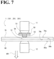
FIGS. 7 to 9 illustrate a method of coupling using the coupling member 50. In this method of coupling, first, the electrode 11 is moved to a position at the side of the coupling member 50, and the electrode 12 is moved to a position at the side of the second plate 80. This causes the coupling member 50, the first plate 70, and the second plate 80 to held between the electrodes 11 and 12.
This results in the contact state illustrated in FIG. 7. Specifically:
(1) the leading end of the electrode 11 and the body 51 of the coupling member 50 are in contact with each other;
(2) the pilot portion 53 of the coupling member 50 and a first main surface 70 a of the first plate 70 are in contact with each other;
(3) a second main surface 70 b of the first plate 70 and a first main surface 80 a of the second plate 80 are in contact with each other, and
(4) a second main surface 80 b of the second plate 80 and the leading end of the electrode 12 are in contact with each other.
As used herein, the term “main surface” of the first plate 70 refers to a main surface among the outer surfaces of the first plate 70. In the example illustrated in FIG. 7, the first main surface 70 a refers to a plane with a normal vector in the extending direction (the arrow AR1 direction). Also, the second main surface 70 b refers to the surface opposite to the first main surface 70 a.
Similarly, the term “main surface” of the second plate 80 refers to a main surface among the outer surfaces of the second plate 80. In the example illustrated in FIG. 7, the first main surface 80 a refers to a plane with a normal vector in the extending direction. Also, the second main surface 80 b refers to the surface opposite to the first main surface 80 a.
Then, with the contact state (1) to (4) maintained, the controller 40 controls the power source 20 to electrify the coupling member 50, the first plate 70, and the second plate 80 while controlling the driver 30 to apply pressure to the coupling member 50, the first plate 70, and the second plate 80.
This causes a facing portion 72 (see FIG. 7) of the first plate 70, which faces the pilot portion 53 of the coupling member 50, to be melted, resulting in a through hole 73 (see FIG. 8) formed at a position corresponding to the facing portion 72. Also, the melted first metal of the facing portion 72 is discharged to a farther side of the pilot portion 53 through a plurality of discharge grooves 59 formed on the flat surface 51 a (see vertical hatching illustrated in FIG. 8).
As a result of the melting of the facing portion 72, the leading end 55 of the pilot portion 53 and a joint portion 82 of the second plate 80 (see FIG. 9) come into contact with each other. Then, the leading end 55 and the joint portion 82 are melted and solidified by resistance welding, and thus are coupled to each other.
1.4. Advantages of Coupling Device According to First Embodiment
As has been described hereinbefore, in the coupling member 50 according to the first embodiment, on the flat surface 51 a of the body 51, the plurality of discharge grooves 59 are formed radially extending from the pilot portion 53. Also, the facing portion 72 of the first plate 70 has a melting point lower than the melting point of the coupling member 50 and the melting point of the second plate 80. This ensures that when the coupling member 50, the first plate 70, and the second plate 80 are applied pressure and electrified, the facing portion 72 is melted and discharged into the discharge grooves 59 of the coupling member 50.
Melting and discharging the facing portion 72 to the discharge grooves 59 prevents the melted first metal from being left between the flat surface 51 a of the coupling member 50 and the first plate 70. This, in turn, prevents the coupling member 50 from being removed from the first plate 70, and eliminates or minimizes insufficient contact between the flat surface 51 a of the coupling member 50 and the first plate 70.
Melting and discharging the facing portion 72 into the discharge grooves 59 also ensures a sufficient level of contact between the pilot portion 53 of the coupling member 50 and the second plate 80. This leads to a sufficient level of coupling between the leading end 55 of the pilot portion 53 and the joint portion 82 of the second plate 80 implemented by resistance welding.
Additionally, the first plate 70 and the second plate 80, which have different melting points, are readily coupled to each other through a single pressure-electrification step.
2. Second Embodiment
The second embodiment of the present invention will be described. The coupling device 1 according to the first embodiment and a coupling device 101 according to the second embodiment are similar to each other in configuration except that the coupling member 50 of the coupling device 1 and a coupling member 150 of the coupling device 101 have different configurations. The following description will focus on those respects in which the coupling member 50 and the coupling member 150 are different from each other.
It is noted that identical reference numerals are used to denote identical or substantially identical components between the coupling devices 1 and 101, and these components have already been described in the first embodiment. To avoid redundancy, these components will not be elaborated upon in the following description.
FIG. 3 and FIGS. 10 to 12 are respectively a plan view, a perspective view, a bottom view, and a front view of the coupling member 150 according to the second embodiment. FIG. 13 is a cross-sectional view, taken along the line A-A illustrated in FIG. 3, of the coupling member 150. The coupling member 150 couples (fastens) the first plate 70 and the second plate 80 to each other by resistance welding, similarly to the coupling member 50 according to the first embodiment. As illustrated in FIG. 3 and FIGS. 10 to 13, the coupling member 150 mainly includes the body 51 and a pilot portion 153.
The body 51 is a circular flat plate. The pilot portion 153 is provided approximately at the center of the flat surface 51 a of the body 51, and protrudes in the extending direction. Also, on the flat surface 51 a, a plurality (four, in the second embodiment) of discharge grooves 59 are formed radially extending from the pilot portion 153.
As illustrated in FIG. 13, a leading end 155 of the pilot portion 153 has a conical shape. A body 154 of the pilot portion 153 has an outer circumference length in the direction perpendicular to the extending direction, and the outer circumference length increases as the body 154 is further away from the flat surface 51 a.
This configuration ensures that when the coupling member 150, the first plate 70, and the second plate 80 are applied pressure and electrified, the facing portion 72 of the first plate 70, which is lower in melting point than the coupling member 150 and the second plate 80, is melted and discharged to the farther side of the pilot portion 153 through the plurality of discharge grooves 59.
Melting and discharging the facing portion 72 to the farther side of the pilot portion 153 prevents the melted first metal from being left between the flat surface 51 a of the coupling member 150 and the first plate 70. Melting and discharging the facing portion 72 to the farther side of the pilot portion 153 also ensures a sufficient level of contact between the pilot portion 153 of the coupling member 150 and the second plate 80. This leads to a sufficient level of coupling between the leading end 155 of the pilot portion 153 and the joint portion 82 of the second plate 80 implemented by resistance welding.
Additionally, the first plate 70 and the second plate 80, which have different melting points, are readily coupled to each other through a single pressure-electrification step.
3. Third Embodiment
The third embodiment of the present invention will be described. The coupling device 1 according to the first embodiment and a coupling device 201 according to the third embodiment are similar to each other in configuration except that the coupling member 50 of the coupling device 1 and a coupling member 250 of the coupling device 201 have different configurations. The following description will focus on those respects in which the coupling member 50 and the coupling member 250 are different from each other.
It is noted that identical reference numerals are used to denote identical or substantially identical components between the coupling devices 1 and 201, and these components have already been described in the first embodiment. To avoid redundancy, these components will not be elaborated upon in the following description.
FIG. 3 and FIGS. 14 to 16 are respectively a plan view, a perspective view, a bottom view, and a front view of the coupling member 250 according to the third embodiment. FIG. 17 is a cross-sectional view, taken along the line A-A illustrated in FIG. 3, of the coupling member 250. The coupling member 250 couples (fastens) the first plate 70 and the second plate 80 to each other by resistance welding, similarly to the coupling member 50 according to the first embodiment. As illustrated in FIG. 3 and FIGS. 14 to 17, the coupling member 250 mainly includes the body 51 and the pilot portion 253.
The body 51 is a circular flat plate. The pilot portion 253 is provided approximately at the center of the flat surface 51 a of the body 51, and protrudes in the extending direction. Also, on the flat surface 51 a, a plurality (four, in the third embodiment) of discharge grooves 59 are formed radially extending from the pilot portion 253.
As illustrated in FIG. 17, the leading end 255 of the pilot portion 253 has a conical shape. A body 254 of the pilot portion 253 has an outer circumference length in the direction perpendicular to the extending direction, and the outer circumference length decreases as the body 254 is further away from the flat surface 51 a.
This configuration ensures that when the coupling member 250, the first plate 70, and the second plate 80 are applied pressure and electrified, the facing portion 72 of the first plate 70, which is lower in melting point than the coupling member 250 and the second plate 80, is melted and discharged to the farther side of the pilot portion 253 through the plurality of discharge grooves 59.
Melting and discharging the facing portion 72 to the farther side of the pilot portion 253 prevents the melted first metal from being left between the flat surface 51 a of the coupling member 250 and the first plate 70. Melting and discharging the facing portion 72 to the farther side of the pilot portion 253 also ensures a sufficient level of contact between the pilot portion 253 of the coupling member 250 and the second plate 80. This leads to a sufficient level of coupling between the leading end 255 of the pilot portion 253 and the joint portion 82 of the second plate 80 implemented by resistance welding.
Additionally, the first plate 70 and the second plate 80, which have different melting points, are readily coupled to each other through a single pressure-electrification step.
4. Fourth Embodiment
The fourth embodiment of the present invention will be described. The coupling device 1 according to the first embodiment and a coupling device 301 according to the fourth embodiment are similar to each other in configuration except that the coupling member 50 of the coupling device 1 and a coupling member 350 of the coupling device 301 have different configurations. The following description will focus on those respects in which the coupling member 50 and the coupling member 350 are different from each other.
It is noted that identical reference numerals are used to denote identical or substantially identical components between the coupling devices 1 and 301, and these components have already been described in the first embodiment. To avoid redundancy, these components will not be elaborated upon in the following description.
FIG. 3 and FIGS. 18 to 20 are respectively a plan view, a perspective view, a bottom view, and a front view of the coupling member 350 according to the fourth embodiment. FIG. 21 is a cross-sectional view, taken along the line A-A illustrated in FIG. 3, of the coupling member 350. The coupling member 350 couples (fastens) the first plate 70 and the second plate 80 to each other by resistance welding, similarly to the coupling member 50 according to the first embodiment. As illustrated in FIG. 3 and FIGS. 18 to 21, the coupling member 350 mainly includes the body 51 and a pilot portion 353.
The body 51 is a circular flat plate. The pilot portion 353 is provided approximately at the center of the flat surface 51 a of the body 51, and protrudes in the extending direction. Also, on the flat surface 51 a, a plurality (four, in the fourth embodiment) of discharge grooves 59 are formed radially extending from the pilot portion 353.
As illustrated in FIG. 21, the pilot portion 353 includes a protrusion 357 on a leading end 355 of the pilot portion 353. The protrusion 357 is provided at or around an axis 353 b of the pilot portion 353. A body 354 of the pilot portion 353 has an outer circumference length in the direction perpendicular to the extending direction, and the outer circumference length is approximately uniform throughout an outer circumference surface 353 a.
This configuration ensures that when the coupling member 350, the first plate 70, and the second plate 80 are applied pressure and electrified, the facing portion 72 of the first plate 70, which is lower in melting point than the coupling member 350 and the second plate 80, is melted and discharged to the farther side of the pilot portion 353 through the plurality of discharge grooves 59.
Melting and discharging the facing portion 72 to the farther side of the pilot portion 353 prevents the melted first metal from being left between the flat surface 51 a of the coupling member 350 and the first plate 70. Melting and discharging the facing portion 72 to the farther side of the pilot portion 353 also ensures a sufficient level of contact between the pilot portion 353 of the coupling member 350 and the second plate 80. This leads to a sufficient level of coupling between the protrusion 357 of the pilot portion 353 and the joint portion 82 of the second plate 80 implemented by resistance welding.
Additionally, the first plate 70 and the second plate 80, which have different melting points, are readily coupled to each other through a single pressure-electrification step.
5. Fifth Embodiment
The fifth embodiment of the present invention will be described. The coupling device 1 according to the first embodiment and a coupling device 401 according to the fifth embodiment are similar to each other in configuration except that the coupling member 50 of the coupling device 1 and a coupling member 450 of the coupling device 401 have different configurations. The following description will focus on those respects in which the coupling member 50 and the coupling member 450 are different from each other.
It is noted that identical reference numerals are used to denote identical or substantially identical components between the coupling devices 1 and 401, and these components have already been described in the first embodiment. To avoid redundancy, these components will not be elaborated upon in the following description.
5.1. Configuration of Coupling Member
FIG. 3 and FIGS. 22 to 24 are respectively a perspective view, a plan view, a bottom view, and a front view of the coupling member 450 according to the fifth embodiment. FIG. 25 is a cross-sectional view, taken along the line A-A illustrated in FIG. 3, of the coupling member 450. The coupling member 450 couples (fastens) the first plate 70 and the second plate 80 to each other by resistance welding. As illustrated in FIGS. 22 to 25, the coupling member 450 mainly includes the body 51, the pilot portion 453, and a ring-shaped wall 458.
The body 51 is a circular flat plate. The pilot portion 453 is provided approximately at the center of the flat surface 51 a of the body 51, and protrudes in the extending direction. The ring-shaped wall 458 is a cylindrical structure provided along the outer circumference of the flat surface 51 a. Also, on the ring-shaped end surface 458 b of the ring-shaped wall 458, a plurality (four, in the fifth embodiment) of notch-shaped discharge grooves are formed.
As illustrated in FIG. 25, the leading end 455 of the pilot portion 453 has a conical shape. The body 454 of the pilot portion 453 has an outer circumference length in a direction perpendicular to the extending direction, and the outer circumference length is approximately uniform throughout the outer circumference surface 453 a.
The ring-shaped wall 458 has an inner circumference length in the direction perpendicular to the extending direction, and the inner circumference length is approximately uniform throughout the inner circumference surface 458 a. Also as illustrated in FIG. 25, an inner surface 458 a of the ring-shaped wall 458, the flat surface 51 a of the body 51, and the outer surface 453 a of the pilot portion 453 define a groove space 450 a.
5.2. Method of Coupling Using Coupling Member
FIGS. 26 to 28 illustrate a method of coupling using the coupling member 450. In this method of coupling, first, the electrode 11 is moved to a position at the side of the coupling member 450, and the electrode 12 is moved to a position at the side of the second plate 80. This causes the coupling member 450, the first plate 70, and the second plate 80 to held between the electrodes 11 and 12.
This results in the contact state illustrated in FIG. 26. Specifically:
(1) the leading end of the electrode 11 and the body 51 of the coupling member 450 are in contact with each other;
(2) the pilot portion 453 of the coupling member 450 and a first main surface 70 a of the first plate 70 are in contact with each other;
(3) a second main surface 70 b of the first plate 70 and a first main surface 80 a of the second plate 80 are in contact with each other, and
(4) a second main surface 80 b of the second plate 80 and the leading end of the electrode 12 are in contact with each other.
Then, with the contact state (1) to (4) maintained, the controller 40 controls the power source 20 to electrify the coupling member 450, the first plate 70, and the second plate 80 while controlling the driver 30 to apply pressure to the coupling member 450, the first plate 70, and the second plate 80.
This causes a facing portion 72 (see FIG. 26) of the first plate 70, which faces the pilot portion 453 of the coupling member 450, to be melted, resulting in a through hole 73 (see FIG. 27) formed at a position corresponding to the facing portion 72. Also, the melted first metal of the facing portion 72 is moved into the groove space 450 a of the coupling member 450. Then, occasionally, part of the melted metal discharged into the groove space 450 a of the coupling member 450 is discharged to the farther side of the pilot portion 453 through a plurality of discharge grooves 459 formed on the ring-shaped end surface 458 b (see vertical hatching illustrated in FIG. 27).
As a result of the melting of the facing portion 72, the leading end 455 of the pilot portion 453 and a joint portion 82 (see FIG. 28) of the second plate 80 come into contact with each other. Then, the leading end 455 and the joint portion 82 are melted and solidified by resistance welding, and thus are coupled to each other.
5.3. Advantages of Coupling Device According to Fifth Embodiment
As has been described hereinbefore, in the coupling member 450 according to the fifth embodiment, on the ring-shaped end surface 458 b of the ring-shaped wall 458, the plurality of notch-shaped discharge grooves are formed. Also, an inner surface 458 a of the ring-shaped wall 458, the flat surface 51 a of the body 51, and the outer surface 453 a of the pilot portion 453 define a groove space 450 a.
Additionally, this configuration ensures that when the coupling member 450, the first plate 70, and the second plate 80 are applied pressure and electrified, the facing portion 72 of the first plate 70, which is lower in melting point than the coupling member 450 and the second plate 80, is melted and discharged into the groove space 450 a of the coupling member 450. Also, occasionally, part of the melted metal discharged into the groove space 450 a of the coupling member 450 is discharged to the farther side of the pilot portion 453 through the plurality of ring-shaped walls 458 formed on the ring-shaped end surface 458 b.
This prevents the melted first metal from being left between the ring-shaped wall 458 of the coupling member 450 and the first plate 70. This, in turn, prevents the coupling member 450 from being removed from the first plate 70, and eliminates or minimizes insufficient contact between the ring-shaped end surface 458 b of the ring-shaped wall 458 and the first plate 70.
This also ensures a sufficient level of contact between the pilot portion 453 of the coupling member 450 and the second plate 80. This leads to a sufficient level of coupling between the leading end 455 of the pilot portion 453 and the joint portion 82 of the second plate 80 implemented by resistance welding.
Additionally, the first plate 70 and the second plate 80, which have different melting points, are readily coupled to each other through a single pressure-electrification step.
6. Sixth Embodiment
The sixth embodiment of the present invention will be described. The coupling device 1 according to the first embodiment and a coupling device 501 according to the sixth embodiment are similar to each other in configuration except that the coupling member 50 of the coupling device 1 and a coupling member 550 of the coupling device 501 have different configurations. The following description will focus on those respects in which the coupling member 50 and the coupling member 550 are different from each other.
It is noted that identical reference numerals are used to denote identical or substantially identical components between the coupling devices 1 and 501, and these components have already been described in the first embodiment. To avoid redundancy, these components will not be elaborated upon in the following description.
FIG. 3 and FIGS. 29 to 31 are respectively a plan view, a perspective view, a bottom view, and a front view of the coupling member 550 according to the sixth embodiment. FIG. 32 is a cross-sectional view, taken along the line A-A illustrated in FIG. 3, of the coupling member 550. The coupling member 550 couples (fastens) the first plate 70 and the second plate 80 to each other by resistance welding, similarly to the coupling member 50 according to the first embodiment. As illustrated in FIG. 3 and FIGS. 29 to 32, the coupling member 550 mainly includes the body 51 and a pilot portion 553.
The body 51 is a circular flat plate. The pilot portion 553 is provided approximately at the center of the flat surface 51 a of the body 51, and protrudes in the extending direction. The ring-shaped wall 458 is a cylindrical structure provided along the outer circumference of the flat surface 51 a. Also, on the ring-shaped end surface 458 b of the ring-shaped wall 458, a plurality (four, in the sixth embodiment) of notch-shaped discharge grooves are formed.
As illustrated in FIG. 32, a leading end 555 of the pilot portion 553 has a conical shape. A body 554 of the pilot portion 553 has an outer circumference length in the direction perpendicular to the extending direction, and the outer circumference length increases as the body 554 is further away from the flat surface 51 a.
The ring-shaped wall 458 has an inner circumference length in the direction perpendicular to the extending direction, and the inner circumference length is approximately uniform throughout the inner circumference surface 458 a. Also as illustrated in FIG. 32, the inner surface 458 a of the ring-shaped wall 458, the flat surface 51 a of the body 51, and an outer surface 553 a of the pilot portion 553 define a groove space 550 a.
This configuration ensures that when the coupling member 550, the first plate 70, and the second plate 80 are applied pressure and electrified, the facing portion 72 of the first plate 70, which is lower in melting point than the coupling member 550 and the second plate 80, is melted and discharged into the groove space 550 a of the coupling member 550. Then, occasionally, part of the melted metal discharged into the groove space 550 a of the coupling member 550 is discharged to the farther side of the pilot portion 553 through the plurality of discharge grooves 459 formed on the ring-shaped end surface 458 b.
This prevents the melted first metal from being left between the ring-shaped wall 458 of the coupling member 550 and the first plate 70. Melting and discharging the facing portion 72 to the farther side of the pilot portion 553 also ensures a sufficient level of contact between the pilot portion 553 of the coupling member 550 and the second plate 80. This leads to a sufficient level of coupling between the leading end 555 of the pilot portion 553 and the joint portion 82 of the second plate 80 implemented by resistance welding.
Additionally, the first plate 70 and the second plate 80, which have different melting points, are readily coupled to each other through a single pressure-electrification step.
7. Seventh Embodiment
The seventh embodiment of the present invention will be described. The coupling device 1 according to the first embodiment and a coupling device 601 according to the seventh embodiment are similar to each other in configuration except that the coupling member 50 of the coupling device 1 and a coupling member 650 of the coupling device 601 have different configurations. The following description will focus on those respects in which the coupling member 50 and the coupling member 650 are different from each other.
It is noted that identical reference numerals are used to denote identical or substantially identical components between the coupling devices 1 and 601, and these components have already been described in the first embodiment. To avoid redundancy, these components will not be elaborated upon in the following description.
FIG. 3 and FIGS. 33 to 35 are respectively a plan view, a perspective view, a bottom view, and a front view of the coupling member 650 according to the seventh embodiment. FIG. 36 is a cross-sectional view, taken along the line A-A illustrated in FIG. 3, of the coupling member 650. The coupling member 650 couples (fastens) the first plate 70 and the second plate 80 to each other by resistance welding, similarly to the coupling member 50 according to the first embodiment. As illustrated in FIG. 3 and FIGS. 33 to 36, the coupling member 650 mainly includes the body 51 and a pilot portion 653.
The body 51 is a circular flat plate. The pilot portion 653 is provided approximately at the center of the flat surface 51 a of the body 51, and protrudes in the extending direction. The ring-shaped wall 458 is a cylindrical structure provided along the outer circumference of the flat surface 51 a. Also, on the ring-shaped end surface 458 b of the ring-shaped wall 458, a plurality (four, in the seventh embodiment) of notch-shaped discharge grooves are formed.
As illustrated in FIG. 36, a leading end 655 of the pilot portion 653 has a conical shape. A body 654 of the pilot portion 653 has an outer circumference length in the direction perpendicular to the extending direction, and the outer circumference length decreases as the body 654 is further away from the flat surface 51 a.
The ring-shaped wall 458 has an inner circumference length in the direction perpendicular to the extending direction, and the inner circumference length is approximately uniform throughout the inner circumference surface 458 a. Also as illustrated in FIG. 36, an inner surface 458 a of the ring-shaped wall 458, the flat surface 51 a of the body 51, and an outer surface 653 a of the pilot portion 653 define a groove space 650 a.
This configuration ensures that when the coupling member 650, the first plate 70, and the second plate 80 are applied pressure and electrified, the facing portion 72 of the first plate 70, which is lower in melting point than the coupling member 650 and the second plate 80, is melted and discharged into the groove space 650 a of the coupling member 650. Then, occasionally, part of the melted metal discharged into the groove space 650 a of the coupling member 650 is discharged to the farther side of the pilot portion 653 through the plurality of discharge grooves 459 formed on the ring-shaped end surface 458 b.
This prevents the melted first metal from being left between the ring-shaped wall 458 of the coupling member 650 and the first plate 70. Melting and discharging the facing portion 72 into the groove space 650 a and to the farther side of the pilot portion 653 also ensures a sufficient level of contact between the pilot portion 653 of the coupling member 650 and the second plate 80. This leads to a sufficient level of coupling between the leading end 655 of the pilot portion 653 and the joint portion 82 of the second plate 80 implemented by resistance welding.
Additionally, the first plate 70 and the second plate 80, which have different melting points, are readily coupled to each other through a single pressure-electrification step.
8. Eighth Embodiment
The eighth embodiment of the present invention will be described. The coupling device 1 according to the first embodiment and a coupling device 701 according to the eighth embodiment are similar to each other in configuration except that the coupling member 50 of the coupling device 1 and a coupling member 750 of the coupling device 701 have different configurations. The following description will focus on those respects in which the coupling member 50 and the coupling member 750 are different from each other.
It is noted that identical reference numerals are used to denote identical or substantially identical components between the coupling devices 1 and 701, and these components have already been described in the first embodiment. To avoid redundancy, these components will not be elaborated upon in the following description.
FIG. 3 and FIGS. 37 to 39 are respectively a plan view, a perspective view, a bottom view, and a front view of the coupling member 750 according to the eighth embodiment. FIG. 40 is a cross-sectional view, taken along the line A-A illustrated in FIG. 3, of the coupling member 750. The coupling member 750 couples (fastens) the first plate 70 and the second plate 80 to each other by resistance welding, similarly to the coupling member 50 according to the first embodiment. As illustrated in FIG. 3 and FIGS. 37 to 40, the coupling member 750 mainly includes the body 51 and a pilot portion 753.
The body 51 is a circular flat plate. The pilot portion 753 is provided approximately at the center of the flat surface 51 a of the body 51, and protrudes in the extending direction. The ring-shaped wall 458 is a cylindrical structure provided along the outer circumference of the flat surface 51 a. Also, on the ring-shaped end surface 458 b of the ring-shaped wall 458, a plurality (four, in the eighth embodiment) of notch-shaped discharge grooves are formed.
As illustrated in FIG. 40, the pilot portion 753 includes a protrusion 757 on a leading end 755 of the pilot portion 753. The protrusion 757 is provided at or around an axis 753 b of the pilot portion 753. A body 754 of the pilot portion 753 has an outer circumference length in the direction perpendicular to the extending direction, and the outer circumference length is approximately uniform throughout an outer circumference surface 753 a.
The ring-shaped wall 458 has an inner circumference length in the direction perpendicular to the extending direction, and the inner circumference length is approximately uniform throughout the inner circumference surface 458 a. Also as illustrated in FIG. 40, the inner surface 458 a of the ring-shaped wall 458, the flat surface 51 a of the body 51, and an outer surface 753 a of the pilot portion 753 define a groove space 750 a.
This configuration ensures that when the coupling member 750, the first plate 70, and the second plate 80 are applied pressure and electrified, the facing portion 72 of the first plate 70, which is lower in melting point than the coupling member 750 and the second plate 80, is melted and discharged into the groove space 750 a of the coupling member 750. Then, occasionally, part of the melted metal discharged into the groove space 750 a of the coupling member 750 is discharged to the farther side of the pilot portion 753 through the plurality of discharge grooves 459 formed on the ring-shaped end surface 458 b.
This prevents the melted first metal from being left between the ring-shaped wall 458 of the coupling member 750 and the first plate 70. Melting and discharging the facing portion 72 into the groove space 750 a and to the farther side of the pilot portion 753 also ensures a sufficient level of contact between the pilot portion 753 of the coupling member 750 and the second plate 80. This leads to a sufficient level of coupling between the protrusion 757 of the pilot portion 753 and the joint portion 82 of the second plate 80 implemented by resistance welding.
Additionally, the first plate 70 and the second plate 80, which have different melting points, are readily coupled to each other through a single pressure-electrification step.
9. Modifications
Possible modifications of the above-described embodiments will be described.
(1) In the first to fourth embodiments of the present invention, four discharge grooves 59 are formed on the flat surface 51 a. This configuration, however, is not intended in a limiting sense. In a possible modification, the number of the discharge grooves 59 is two, three, five or more. In another possible modification, the number of the discharge grooves is two or more.
(2) Also, in the fifth to eighth embodiments of the present invention, four discharge grooves 59 are formed on the ring-shaped end surface 458 b of the ring-shaped wall 458. This configuration, however, is not intended in a limiting sense. In a possible modification, the number of the discharge grooves 459 is two, three, five or more. In another possible modification, the number of the discharge grooves 459 is two or more.
(3) Also, in the fourth and eighth embodiments of the present invention, the body of the pilot portion has an outer circumference length in the direction perpendicular to the extending direction, and the outer circumference length is approximately uniform throughout the outer circumference surface. This configuration, however, is not intended in a limiting sense.
In a possible modification, the outer circumference length of the body of the pilot portion in the direction perpendicular to the extending direction increases or decreases as the body is further away from the flat surface 51 a.
(4) Also, in the fifth and eighth embodiments of the present invention, the inner circumference length of the ring-shaped wall 458 in the direction perpendicular to the extending direction, and the inner circumference length is approximately uniform throughout the inner circumference surface 458 a. This configuration, however, is not intended in a limiting sense.
In a possible modification, the inner circumference length of the ring-shaped wall 458 in the direction perpendicular to the extending direction increases or decreases as the body is further away from the flat surface 51 a.
(5) Also, in the first to eighth embodiments of the present invention, the driver 30 moves the electrodes 11 and 12 in the vertical directions relative to the coupling member 50, the first plate 70, and the second plate 80. This, however, is not intended as limiting how to move the electrodes 11 and 12.
In a possible modification, the electrode 11 is fixed and the electrode 12 is movable in the vertical directions. In another possible modification, the electrode 12 is fixed and the electrode 11 is movable in the vertical directions. Thus, such a configuration suffices that at least one of the electrodes 11 and 12 is movable relative to the other electrode.
Obviously, numerous modifications and variations of the present invention are possible in light of the above teachings. It is therefore to be understood that within the scope of the appended claims, the present invention may be practiced otherwise than as specifically described herein.

Claims (6)

What is claimed is:
1. A coupling device configured to, using a coupling member, couple a first plate made of a first metal and a second plate made of a second metal to each other, the coupling device comprising:
(a) a first electrode and a second electrode;
(b) a power source connected to the first electrode and the second electrode;
(c) a driver configured to move the first electrode and the second electrode relative to the coupling member, the first plate, and the second plate; and
(d) a controller configured to control the power source and the driver to electrify the coupling member, the first plate, and the second plate while controlling the first electrode and the second electrode to apply pressure to the coupling member, the first plate, and the second plate,
wherein the coupling member is made of a third metal approximately identical to the second metal,
wherein the first metal has a melting point lower than a melting point of the second metal and a melting point of the third metal,
wherein the coupling member comprises
a body, and
a pilot portion provided approximately at a center of a flat surface of the body and protruding in an extending direction,
wherein, on the flat surface, a plurality of discharge grooves are formed radially extending from the pilot portion,
wherein the pilot portion is solid,
wherein the controller is configured to make the coupling member, the first plate, and the second plate held between the first electrode and the second electrode so as to make a contact state between:
a leading end of the first electrode and the body of the coupling member;
the pilot portion of the coupling member and a first main surface of the first plate;
a second main surface of the first plate and a first main surface of the second plate; and
a second main surface of the second plate and a leading end of the second electrode, and
wherein the controller is configured to, while maintaining the contact state, control the power source to electrify the coupling member, the first plate, and the second plate while controlling the driver to apply pressure to the coupling member, the first plate, and the second plate so as to:
(i) melt a facing portion of the first plate facing the pilot portion of the coupling member, and discharge the melted facing portion to a farther side of the pilot portion through the plurality of discharge grooves formed on the coupling member, whereby the facing portion is removed, allowing a leading end of the pilot portion and a joint portion of the second plate to contact each other; and
(ii) melt and solidify the leading end of the pilot portion and the joint portion of the second plate to couple the leading end of the pilot portion and the joint portion of the second plate to each other.
2. The coupling device according to claim 1,
wherein a body of the pilot portion has an outer circumference length in a direction perpendicular to the extending direction, the outer circumference length being approximately uniform throughout the body of the pilot portion.
3. The coupling device according to claim 1,
wherein a body of the pilot portion has an outer circumference length in a direction perpendicular to the extending direction, the outer circumference length increasing as the body of the pilot portion is further away from the flat surface.
4. The coupling device according to claim 1,
wherein a body of the pilot portion has an outer circumference length in a direction perpendicular to the extending direction, the outer circumference length decreasing as the body of the pilot portion is further away from the flat surface.
5. The coupling device according to claim 2,
wherein the leading end of the pilot portion has a conical shape.
6. The coupling device according to claim 2,
wherein the leading end of the pilot portion comprises a protrusion provided at or around an axis of the pilot portion.
US16/286,603 2016-08-27 2019-02-27 Coupling device Active 2037-08-08 US11273513B2 (en)

Applications Claiming Priority (1)

Application Number Priority Date Filing Date Title
PCT/JP2016/075105 WO2018042472A1 (en) 2016-08-27 2016-08-27 Coupling device

Related Parent Applications (1)

Application Number Title Priority Date Filing Date
PCT/JP2016/075105 Continuation WO2018042472A1 (en) 2016-08-27 2016-08-27 Coupling device

Publications (2)

Publication Number Publication Date
US20190193189A1 US20190193189A1 (en) 2019-06-27
US11273513B2 true US11273513B2 (en) 2022-03-15

Family

ID=61301751

Family Applications (1)

Application Number Title Priority Date Filing Date
US16/286,603 Active 2037-08-08 US11273513B2 (en) 2016-08-27 2019-02-27 Coupling device

Country Status (5)

Country Link
US (1) US11273513B2 (en)
EP (1) EP3505292A4 (en)
JP (1) JP6361061B1 (en)
CN (1) CN109641311B (en)
WO (1) WO2018042472A1 (en)

Families Citing this family (2)

* Cited by examiner, † Cited by third party
Publication number Priority date Publication date Assignee Title
DE102019106160A1 (en) * 2019-03-11 2020-09-17 Böllhoff Verbindungstechnik GmbH CONNECTING METHOD FOR AT LEAST TWO COMPONENTS, A JOINING CONNECTION ACHIEVED THEREOF AND A JOINING DEVICE FOR THE MENTIONED CONNECTING METHOD
JP7659259B2 (en) * 2021-01-22 2025-04-09 株式会社神戸製鋼所 Fastener connecting device, fastener feeding method, connecting method, and manufacturing method of connected body

Citations (6)

* Cited by examiner, † Cited by third party
Publication number Priority date Publication date Assignee Title
JPH0833987A (en) 1994-07-25 1996-02-06 Akane:Kk Method and apparatus for joining dissimilar materials
US20090294410A1 (en) 2008-05-28 2009-12-03 Kabushiki Kaisha Kobe Seiko Sho (Kobe Steel Ltd) Method for joining dissimilar metals of steel product and light metal product with each other
WO2013064618A1 (en) 2011-11-04 2013-05-10 Newfrey Llc Fastener for welding having a shank and a flange with projections, joining method and joining connection using such fastener
JP2015042417A (en) 2013-07-22 2015-03-05 株式会社神戸製鋼所 Dissimilar material joining rivet, dissimilar material joining member, dissimilar material joining method, and dissimilar material joining
US20150258624A1 (en) 2012-09-25 2015-09-17 Boellhoff Verbindungstechnik Gmbh Welding auxiliary joining part and method for connecting components by way of said welding auxiliary joining part
US20160167158A1 (en) * 2014-12-15 2016-06-16 Alcoa Inc. Resistance welding fastener, apparatus and methods for joining similar and dissimilar materials

Patent Citations (9)

* Cited by examiner, † Cited by third party
Publication number Priority date Publication date Assignee Title
JPH0833987A (en) 1994-07-25 1996-02-06 Akane:Kk Method and apparatus for joining dissimilar materials
US20090294410A1 (en) 2008-05-28 2009-12-03 Kabushiki Kaisha Kobe Seiko Sho (Kobe Steel Ltd) Method for joining dissimilar metals of steel product and light metal product with each other
JP2009285678A (en) 2008-05-28 2009-12-10 Kobe Steel Ltd Dissimilar material joining method and dissimilar material joined body between steel and light alloy, light alloy for joining dissimilar material for steel, and dissimilar material joining rivet between steel and light alloy
WO2013064618A1 (en) 2011-11-04 2013-05-10 Newfrey Llc Fastener for welding having a shank and a flange with projections, joining method and joining connection using such fastener
US20150258624A1 (en) 2012-09-25 2015-09-17 Boellhoff Verbindungstechnik Gmbh Welding auxiliary joining part and method for connecting components by way of said welding auxiliary joining part
JP2015042417A (en) 2013-07-22 2015-03-05 株式会社神戸製鋼所 Dissimilar material joining rivet, dissimilar material joining member, dissimilar material joining method, and dissimilar material joining
US20160123362A1 (en) 2013-07-22 2016-05-05 Kabushiki Kaisha Kobe Seiko Sho (Kobe Steel, Ltd.) Rivet for connecting different materials, member for connecting different materials, method for manufacturing joined body of different materials, and joined body of different materials
US20160167158A1 (en) * 2014-12-15 2016-06-16 Alcoa Inc. Resistance welding fastener, apparatus and methods for joining similar and dissimilar materials
WO2016100179A1 (en) 2014-12-15 2016-06-23 Alcoa Inc. Resistance welding fastener, apparatus and methods for joining similar and dissimilar materials

Non-Patent Citations (7)

* Cited by examiner, † Cited by third party
Title
Chinese Office Action for corresponding CN Application No. 201680088788.3, dated Feb. 25, 2021 (w/ English machine translation).
Chinese Office Action for corresponding CN Application No. 201680088788.3, dated Jul. 2, 2020 (w/ English machine translation).
Extended European Search Report for corresponding EP Application No. 16915033.1-1016, dated Apr. 8, 2020.
International Search Report for corresponding International Application No. PCT/JP2016/075105, dated Feb. 7, 2017.
Japanese Office Action for corresponding JP Application No. 2017-510416, dated May 15, 2018 (w/ English machine translation).
Japanese Office Action for corresponding JP Application No. 2017-510416, dated Nov. 13, 2017 (w/ English machine translation).
Written Opinion for corresponding International Application No. PCT/JP2016/075105, dated Feb. 7, 2017.

Also Published As

Publication number Publication date
WO2018042472A1 (en) 2018-03-08
CN109641311B (en) 2021-09-28
EP3505292A1 (en) 2019-07-03
CN109641311A (en) 2019-04-16
JP6361061B1 (en) 2018-07-25
EP3505292A4 (en) 2020-05-06
US20190193189A1 (en) 2019-06-27
JPWO2018042472A1 (en) 2018-08-30

Similar Documents

Publication Publication Date Title
US11267070B2 (en) Coupling device
US11273513B2 (en) Coupling device
US10603737B2 (en) Different material welded joint and welding method
CN103201909B (en) Connecting parts for electrical conductors
JP7010720B2 (en) Resistance spot welding method
CA2979104C (en) Dissimilar material joined body and dissimilar material joining method
US9803678B2 (en) Arc weld stud having a forming thread
US3996446A (en) Attachment members arranged for weld fastening to a metallic base
WO2018138239A1 (en) Welding element and welding method for connecting a welding element to a workpiece
US10625363B2 (en) Different material welded joint and welding method
CA3013976C (en) Method for manufacturing component
US20190366490A1 (en) Welding base
JP2021074728A (en) Electrode holder
US9893498B2 (en) Method for manufacturing tubular metal shell including ground electrode bar for spark plug, and method for manufacturing spark plug
EP4349497A2 (en) Converter for an ultrasonic welding device having increased arc resistance
EP2248622A1 (en) Joining component and fastening arrangement
KR101608716B1 (en) A cap tip for spot welding
US20190131734A1 (en) Contact assembly and method for forming a contact assembly
JP7297788B2 (en) spot welding method
JP2019048313A (en) Spot welding electrode, welding device and welding method
JP7204290B2 (en) Welding electrodes for indirect spot welding
WO2015155586A1 (en) Method and/or system for alloyed strip welding and cladding; alloyed strip consumable with core material
US20210078096A1 (en) Resistance welding method and resistance welding apparatus
JP2010017740A (en) Stud bolt
KR20180070359A (en) Bead shape for no-indentiation welding

Legal Events

Date Code Title Description
AS Assignment

Owner name: SHINJO HOLDINGS CO., LTD., JAPAN

Free format text: ASSIGNMENT OF ASSIGNORS INTEREST;ASSIGNORS:NISHIMURA, RIKIYA;MASUNAGA, ETSUO;SIGNING DATES FROM 20190222 TO 20190225;REEL/FRAME:048448/0275

FEPP Fee payment procedure

Free format text: ENTITY STATUS SET TO UNDISCOUNTED (ORIGINAL EVENT CODE: BIG.); ENTITY STATUS OF PATENT OWNER: LARGE ENTITY

STPP Information on status: patent application and granting procedure in general

Free format text: NON FINAL ACTION MAILED

STPP Information on status: patent application and granting procedure in general

Free format text: RESPONSE TO NON-FINAL OFFICE ACTION ENTERED AND FORWARDED TO EXAMINER

STPP Information on status: patent application and granting procedure in general

Free format text: NOTICE OF ALLOWANCE MAILED -- APPLICATION RECEIVED IN OFFICE OF PUBLICATIONS

STCF Information on status: patent grant

Free format text: PATENTED CASE

FEPP Fee payment procedure

Free format text: MAINTENANCE FEE REMINDER MAILED (ORIGINAL EVENT CODE: REM.); ENTITY STATUS OF PATENT OWNER: LARGE ENTITY