US11269092B2 - Method and system for optimizing seismic data acquisition using compressed sensing - Google Patents
Method and system for optimizing seismic data acquisition using compressed sensing Download PDFInfo
- Publication number
- US11269092B2 US11269092B2 US16/014,566 US201816014566A US11269092B2 US 11269092 B2 US11269092 B2 US 11269092B2 US 201816014566 A US201816014566 A US 201816014566A US 11269092 B2 US11269092 B2 US 11269092B2
- Authority
- US
- United States
- Prior art keywords
- activation
- survey
- pavements
- seismic
- points
- Prior art date
- Legal status (The legal status is an assumption and is not a legal conclusion. Google has not performed a legal analysis and makes no representation as to the accuracy of the status listed.)
- Active, expires
Links
Images


Classifications
-
- G—PHYSICS
- G01—MEASURING; TESTING
- G01V—GEOPHYSICS; GRAVITATIONAL MEASUREMENTS; DETECTING MASSES OR OBJECTS; TAGS
- G01V1/00—Seismology; Seismic or acoustic prospecting or detecting
- G01V1/003—Seismic data acquisition in general, e.g. survey design
-
- G—PHYSICS
- G01—MEASURING; TESTING
- G01V—GEOPHYSICS; GRAVITATIONAL MEASUREMENTS; DETECTING MASSES OR OBJECTS; TAGS
- G01V1/00—Seismology; Seismic or acoustic prospecting or detecting
- G01V1/02—Generating seismic energy
- G01V1/04—Details
- G01V1/09—Transporting arrangements, e.g. on vehicles
-
- G—PHYSICS
- G01—MEASURING; TESTING
- G01V—GEOPHYSICS; GRAVITATIONAL MEASUREMENTS; DETECTING MASSES OR OBJECTS; TAGS
- G01V2210/00—Details of seismic processing or analysis
- G01V2210/10—Aspects of acoustic signal generation or detection
- G01V2210/12—Signal generation
- G01V2210/127—Cooperating multiple sources
-
- G—PHYSICS
- G01—MEASURING; TESTING
- G01V—GEOPHYSICS; GRAVITATIONAL MEASUREMENTS; DETECTING MASSES OR OBJECTS; TAGS
- G01V2210/00—Details of seismic processing or analysis
- G01V2210/10—Aspects of acoustic signal generation or detection
- G01V2210/12—Signal generation
- G01V2210/129—Source location
- G01V2210/1293—Sea
-
- G—PHYSICS
- G01—MEASURING; TESTING
- G01V—GEOPHYSICS; GRAVITATIONAL MEASUREMENTS; DETECTING MASSES OR OBJECTS; TAGS
- G01V2210/00—Details of seismic processing or analysis
- G01V2210/10—Aspects of acoustic signal generation or detection
- G01V2210/12—Signal generation
- G01V2210/129—Source location
- G01V2210/1295—Land surface
-
- G—PHYSICS
- G01—MEASURING; TESTING
- G01V—GEOPHYSICS; GRAVITATIONAL MEASUREMENTS; DETECTING MASSES OR OBJECTS; TAGS
- G01V2210/00—Details of seismic processing or analysis
- G01V2210/10—Aspects of acoustic signal generation or detection
- G01V2210/14—Signal detection
- G01V2210/142—Receiver location
- G01V2210/1423—Sea
-
- G—PHYSICS
- G01—MEASURING; TESTING
- G01V—GEOPHYSICS; GRAVITATIONAL MEASUREMENTS; DETECTING MASSES OR OBJECTS; TAGS
- G01V2210/00—Details of seismic processing or analysis
- G01V2210/10—Aspects of acoustic signal generation or detection
- G01V2210/14—Signal detection
- G01V2210/142—Receiver location
- G01V2210/1425—Land surface
Definitions
- Embodiments of the subject matter disclosed herein generally relate to methods and systems for designing seismic data acquisition for surveying a predetermined area and, more specifically, to optimizing source path while using compressed sensing and taking into consideration operational constraints.
- Seismic surveys on land and in marine environments are used for generating images of geophysical structures under the Earth's surface or under the seafloor (subsurface). These images enable those trained in the field to estimate the presence and location of oil and gas reservoirs. Obtaining high-resolution images of the subsurface is important to efficient exploration and exploitation of oil and gas reservoirs.
- seismic excitations are injected into the subsurface to probe its structure. These seismic excitations may be generated by an impulsive or a vibratory source. Reflections and refractions of these seismic excitations are detected by seismic receivers, after traveling from the source through the explored subsurface, to produce a seismic data record.
- the seismic data is a series of seismic amplitudes recorded at sampling times. The travel times corresponding to large amplitudes indicate the position of reflection and/or refraction layer interfaces (where the impedance changes inside the subsurface), thereby allowing generation of a structural image thereof.
- Various embodiments design an optimized data acquisition plan for a seismic survey in a given area using a random spatial sampling and complying with operational constraints.
- a method for designing seismic data acquisition in a survey area includes defining non-overlapping successive pavements along a survey path so as to cover the survey area.
- the method further includes sequentially determining activation points of a seismic source inside the pavements, wherein a current activation point in a pavement is selected if included in a set of activation points in successive pavements along the survey path, the set of activation points starting with the current activation point and satisfying predetermined operational constraints.
- a seismic data acquisition system including a seismic source configured to generate seismic excitations that propagate inside an explored underground formation, and receivers configured and placed to detect reflections of the seismic excitations emerging from the explored underground formation.
- the seismic data acquisition system also includes a controller configured to guide the seismic source at activation points.
- the controller determines the activation points by: defining non-overlapping successive pavements along survey path so as to cover a survey area, and sequentially determines the activation points inside pavements along the survey path.
- a current activation point in a pavement is selected if included in a set of activation points in successive pavements along the survey path, the set of activation points starting with the current activation point and satisfying predetermined operational constraints.
- a seismic survey design apparatus including an interface configured to receive information about a survey area and operational constraints, and a processor connected to the interface and configured to define non-overlapping successive pavements along a survey path so as to cover the survey area.
- the processor is further configured to successively determine activation points of a seismic source inside pavements, wherein a current activation point in a pavement is selected if included in a set of activation points in successive pavements along the survey path, the set of activation points starting with the current activation point and satisfying predetermined operational constraints.
- FIG. 1 illustrates a grid of source activation locations for a conventional data acquisition plan
- FIG. 2 illustrates adjacent pavements defined according to an embodiment
- FIG. 3 illustrates the impact of curvature limitation in adjacent pavements according to an embodiment
- FIG. 4 illustrates the impact of angle limitation in adjacent pavements according to an embodiment
- FIG. 5 illustrates a forbidden zone in a pavement according to an embodiment
- FIG. 6 illustrates allowed area when all the operational limitations are taken into consideration
- FIG. 7 is a flowchart of a method according to an embodiment
- FIG. 8 is a schematic data flow according to an embodiment
- FIG. 9 is an illustration of conventionally selected shooting locations in the middle of pavements along a survey line
- FIG. 10 is an illustration of shooting locations inside pavements along a survey line according to an embodiment
- FIG. 11 illustrates a two-dimensional (2D) survey area inside which the shooting points have been selected randomly, without taking into consideration any operational constraints, not even having one shot in each pavement;
- FIG. 12 illustrates the 2D survey area inside which for each pavement one shooting point has been selected randomly according to an embodiment
- FIG. 13 illustrates the 2D survey area inside which one shooting points have been selected randomly in each pavement, taking into consideration all the operational limitations according to an embodiment
- FIG. 14 illustrates the spectral response in a common receiver gather for regularly (on a grid) selected points
- FIG. 15 illustrates the spectral response in a common receiver gather for the randomly selected shooting points in FIG. 11 ;
- FIG. 16 illustrates the spectral response in a common receiver gather for the randomly selected shooting points in FIG. 12 ;
- FIG. 17 illustrates the spectral response in a common receiver gather for the shooting points in FIG. 13 ;
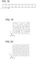
- FIG. 18 is an illustration of shooting locations on sub-grids inside pavements along a survey line according to an embodiment
- FIG. 19 illustrates the 2D survey area, where the shooting points are selected randomly from the sub-grid points without taking into consideration any operational constraint, according to an embodiment
- FIG. 20 illustrates the same 2D survey area in which the shooting points are selected randomly from the sub-grid points with one shooting point in each pavement, according to another embodiment
- FIG. 21 illustrates yet the same 2D survey in which the shooting points have been selected randomly among the sub-grid points, with one shooting point per pavement and taking into consideration all the operational constraints, according to another embodiment
- FIG. 22 illustrates the spectral response in a common receiver gather for the randomly selected shooting points in FIG. 19 ;
- FIG. 23 illustrates the spectral response in a common receiver gather for the randomly selected shooting points with one shooting point in each pavement as in FIG. 20 ;
- FIG. 24 illustrates the spectral response in a common receiver gather for the randomly selected shooting points, with one shooting point per pavement and taking into consideration all the operational constraints as in FIG. 21 ;
- FIG. 25 is a schematic diagram of a seismic data acquisition system according to an embodiment.
- FIG. 26 is a block diagram of a seismic survey design apparatus according to another embodiment.
- the design methods and system described in this section generate a random spatial sampling design of seismic data acquisition efficient and compliant with operational constraints.
- the inventive concept combines a non-random aspect and a random aspect.
- the non-random aspect related to defining non-overlapping successive pavements that cover the survey area.
- the pavements are areas that may have a regular shape (e.g., rectangular or even square, hexagonal, etc.) and may be grouped in survey lines along which the source moves.
- the random aspect relates to associating one random activation point in each pavement.
- this description focusses on vibrator sources moved on land by trucks.
- the vibrators are actuated to generate seismic excitations injected in the underground.
- impulsive sources may also be used and, for this type of sources, the term “shooting” location is more frequently used.
- activation is used for both shooting locations and actuation locations. Note also that “point(s)” and “location(s)” are used interchangeably.
- Defining pavements and picking random points inside each pavement do not ensure an efficient, feasible path for the vibrator.
- the transition from one activation point in one pavement to a next activation point in the next pavement may not be possible due to the limited curvature the truck path may have.
- a tilt larger than a certain limit along the path between activation points may cause the truck to turn over.
- Yet another aspect that may be considered is to minimize/optimize the length of the truck's path and, implicitly, the survey time.
- One way to implement path length optimization is by limiting the magnitude of the acute angle between successive path segments defined by activation points in adjacent pavements.
- FIG. 2 illustrates two adjacent pavements I and I+1, with point A selected in pavement I.
- FIG. 3 illustrates the curvature limitation in pavement I+1, area B being allowed area and area C being forbidden area.
- FIG. 4 illustrates limiting the magnitude of the acute angle between successive path segments, with area D being allowed area and area E being forbidden area.
- FIG. 5 illustrates a forbidden zone G in pavement I+1, while the rest, area F, is allowed. The forbidden zone may be identified based on topological information as an obstacle (e.g., a tree) or determined as having a tilt larger than allowable.
- FIG. 6 illustrates a possible area M for an activation point in pavement I+1 when all these operational constraints are taken into consideration.
- the operational constraints may be related to a set of pavements rather than to only two successive pavements.
- Shooting points in a set of pavements form a scenario that may be validated in the following manner.
- Each constraint is associated with a weight. If the product of the weights associated with constraints which are met exceeds a predetermined threshold then the scenario is validated.
- FIG. 7 is a flowchart illustrating a method 700 for designing seismic data acquisition according to an embodiment.
- Method 700 includes defining non-overlapping successive pavements along survey path so as to cover the survey area at 710 (i.e., the non-random aspect as described above).
- the method further includes, at 720 , sequentially determining activation points of a seismic source inside pavements along the survey path (i.e., the random aspect).
- a current activation point in a pavement is selected if included in a set of activation points in successive pavements along the survey path, the set of activation points starting with the current activation point and satisfying predetermined operational constraints.
- activation points are random within an area allowed by the operational constraints.
- FIG. 8 provides more detailed explanations.
- sets of successive pavements are defined at 820 , with each set including two or more (i.e., N) pavements which may be along a survey line.
- a loop 830 over all sets is executed over all sets of pavements to select the activation points.
- Loop 830 includes, inputting a set of pavements at 832 , choosing randomly a current point in the allowed area (e.g., M in FIG. 6 ) of the first pavement in the set at 834 .
- another loop 836 is executed (as indicated by the “while” condition) as long as 840 not all the points in a current set have an activation point (randomly placed at 842 ) so as to comply with all predetermined operational constraints (tested at 846 ). If the constraints are satisfied, the first activation point is accepted and included in the survey plan (set as current point) at 850 , and another set along the same survey line in the source moving direction is considered.
- the loop 830 ends when all pavements of all sets have selected activation points at 860 . This group simulation and selection of activation points avoids dead-end choices (i.e., choosing an activation point in a pavement that leaves no possible activation points in next pavements along a survey line).
- predetermined operational constraints refers to one or more specific constraints. Some operational constraints may be related to constructive limitations of the survey equipment such as a minimum curvature or a maximum tilt that the seismic source may be subjected to. Other operational constraints may be related to the physical reality in the survey area, e.g., presence of a tree or a water body. Some of these constraints may be inferred from topographic information. However, it is possible that information obtained by direct observation during the survey to cause plan alteration with a newly added constraint. Last but not least, some constraints may arise from the desire to optimize the survey path such as not to extend the survey. Such a constraint may be limiting the acute angle between successive segments formed by actuation pints in adjacent pavements. No limitations should be a priori inferred regarding the number and the type of the predetermined operational constraints.
- the predetermined operational constraints include limitations related to a motion of a seismic source from one activation point to a next activation point.
- limitations related to the motion of the seismic source may be a minimum curvature of a source's path between adjacent activation points, or (alternatively or additionally) a maximum acute angle between successive segments defined by activation points in adjacent pavements.
- the method may further include associating topographic information with the pavements.
- the topographic information may then be used to evaluate one of the predetermined operational constraints.
- the topographic information may be used to evaluate tilt so that the truck/seismic source not to exceed a maximum tilt while moving from one activation point to a next activation point.
- the topographic information may be used to identify forbidden zones within the pavements.
- the pavements may have rectangular, square, hexagonal other shapes.
- in one or more pavements are defined predetermined locations for the activation points. These predetermined locations may form sub-grids.
- FIGS. 9-17 refer to a first case study in which the pavements are squares with a 25 m side, minimum vibrator curvature is 5 m and maximum acute angle between successive segments of the path is 30°.
- FIG. 9 illustrates pavements along a survey line in which the shooting points are selected regularly in the middle of each pavement according to conventional methods. The segment length between successive shooting points is 25 m.
- FIG. 10 illustrates the same pavements, but here the shooting points are selected randomly while taking into consideration operational constraints according to an embodiment.
- the mean length between successive shooting points is 25.5 m (2% longer than the conventional length).
- FIG. 11 illustrates a 2D survey area corresponding to FIG. 1 , where the shooting points are selected randomly without taking into consideration operational constraints, fully random, not even having one shot in each pavement. Note that here the 2D refers to the figure and does not refer to the acquisition, which could be 2D or 3D.
- FIG. 12 illustrates the same 2D survey area in which there is one randomly selected shot in each pavement resulting in an increase of 8% in the mean length between successive shooting points.
- FIG. 13 illustrates yet the same 2D survey in which the shooting points have been selected randomly, one shot in each pavement, taking into consideration operational constraints (i.e., including the acute angle limitation), resulting in another increase of only 2% in the mean length between successive shooting points.
- FIGS. 14-17 illustrate a spatial spectral response for a common receiver gather (i.e., a 2D Fourier transform in a 1 m ⁇ 1 m sub-grid).
- FIG. 14 corresponds to the regular grid in FIG. 1
- FIG. 15 to the random shooting points in FIG. 11
- FIG. 16 to the randomly selected shooting points with one point in each pavement in FIG. 12
- FIG. 17 corresponds to FIG. 13 representing the same 2D survey area in which the shooting points have been selected randomly, one shot in each pavement, by taking into consideration all the operational constraints.
- FIG. 14 Aliasing focus is visible in FIG. 14 .
- FIG. 15 no longer shows aliasing focus, but is flooded by white noise.
- FIG. 16 no longer shows aliasing focus, with white noise present everywhere except around the signal zone (the area in between both the horizontal and vertical pairs of lines corresponding to the small wave number).
- FIG. 17 shows a light aliasing focus (due to the direction limitations) and white noise being present everywhere except around the signal zone.
- FIGS. 18-24 are related to a second case study.
- the pavements and the operational constraints are the same as in the first case but, in this case, as illustrated in FIG. 18 , the shooting points inside each pavement are among four predefined sub-grid corners.
- FIG. 19 illustrates the 2D survey area, where the shooting points are selected randomly from the sub-grid points without taking into consideration any other operational constraints.
- FIG. 20 illustrates the same 2D survey area in which one of the sub-grid points is selected in each pavement, resulting in an increase of 6.6% in the mean length between successive shooting points.
- FIG. 21 illustrates yet the same 2D survey in which the shooting points have been selected randomly among the sub-grid points, one point in each pavement, and all the operational constraints have been considered, resulting in an increase of 2.6% in the mean length between successive shooting points (compared to the regular pattern with shooting in the middle of the pavements).
- FIGS. 22-24 illustrate a spatial spectral response for a common receiver gather (i.e., a 2D Fourier transform in a 1 m ⁇ 1 m sub-grid).
- FIG. 22 corresponds to the randomly selected sub-grid shooting points in FIG. 19
- FIG. 23 to the sub-grid shooting points in FIG. 20
- FIG. 24 corresponds to corresponds to the sub-grid shooting points in FIG. 21 (i.e., representing the same 2D survey area in which the sub-grid shooting points have been selected randomly, one point in each pavement, by taking into consideration all the operational constraints).
- FIGS. 23 and 24 some noise focalization becomes visible, but around the signal zone (the area in between both the horizontal and vertical pairs of lines corresponding to the small wave number) the noise is attenuated.
- the current embodiments provide advantages in terms of data quality for a small added cost. Data quality benefits from signal processing using compressed sensing. Comparing to a classic regularly gridded acquisition, the data acquisition designed with these embodiments does not add significant cost (e.g., a 2-3% longer survey time due to longer path).
- FIG. 25 is a schematic diagram of a land seismic data acquisition system 2500 according to an embodiment.
- System 2500 includes seismic sources carried by trucks 2510 - 2550 along survey lines 2515 - 2555 respectively. Although in principle a single seismic source may be used, using multiple trucks (when available) shortens the survey time.
- System 2500 also includes receivers placed along receiver lines 2560 - 2568 . The receivers are configured and placed to detect reflections of the seismic excitations generated by the seismic source(s) and emerging from the explored underground formation.
- System 2500 also includes a controller 2570 configured to guide the seismic source(s) to the activation points along the survey lines.
- Controller 2570 is an activation points planner (may be on site or remote, operating in real-time and/or performing a pre-survey planning) which determines the activation points by performing the above-described methods according to various embodiments.
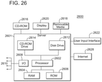
- FIG. 26 is block diagram of a processing device 2600 suitable for performing the activities described in the exemplary embodiments (e.g., controller 2570 ).
- Processing device 2600 includes a server 2601 with a central processor unit (CPU) 2602 coupled to a random access memory (RAM) 2604 and/or to a read-only memory (ROM) 2606 .
- the ROM 2606 may also be other types of storage media to store programs, such as programmable ROM (PROM), erasable PROM (EPROM), etc.
- Processor 2602 may communicate with other internal and external components through input/output (I/O) circuitry 2608 and bussing 2610 to provide control signals and the like.
- I/O input/output
- processor 2602 may communicate with the various elements of each source element.
- Processor 2602 carries out a variety of functions as are known in the art, as dictated by software and/or firmware instructions.
- Server 2601 may also include one or more data storage devices, including disk drives 2612 , CD-ROM drives 2614 , and other hardware capable of reading and/or storing information, such as a DVD, etc.
- software for carrying out the above-discussed steps may be stored and distributed on a CD-ROM 2616 , removable media 2618 or other form of media capable of storing information.
- the storage media may be inserted into, and read by, devices such as the CD-ROM drive 2614 , disk drive 2612 , etc.
- Server 2601 may be coupled to a display 2620 , which may be any type of known display or presentation screen, such as LCD, plasma displays, cathode ray tubes (CRT), etc.
- a user input interface 2622 is provided, including one or more user interface mechanisms such as a mouse, keyboard, microphone, touch pad, touch screen, voice-recognition system, etc.
- Server 2601 may be coupled to other computing devices, such as the equipment of a vessel, via a network.
- the server may be part of a larger network configuration as in a global area network (GAN) such as the Internet 2628 , which allows ultimate connection to various landline and/or mobile client/watcher devices.
- GAN global area network
- the embodiments may be embodied in a wireless communication device, a telecommunication network, as a method or in a computer program product. Accordingly, the embodiments may take the form of an entirely hardware embodiment or an embodiment combining hardware and software aspects. Further, the embodiments may take the form of a computer program product stored on a computer-readable storage medium having computer-readable instructions embodied in the medium. Any suitable computer-readable medium may be utilized, including hard disks, CD-ROMs, digital versatile discs (DVD), optical storage devices or magnetic storage devices such a floppy disk or magnetic tape. Other non-limiting examples of computer-readable media include flash-type memories or other known types of memories.
Landscapes
- Engineering & Computer Science (AREA)
- Remote Sensing (AREA)
- Physics & Mathematics (AREA)
- Life Sciences & Earth Sciences (AREA)
- Acoustics & Sound (AREA)
- Environmental & Geological Engineering (AREA)
- Geology (AREA)
- General Life Sciences & Earth Sciences (AREA)
- General Physics & Mathematics (AREA)
- Geophysics (AREA)
- Geophysics And Detection Of Objects (AREA)
Abstract
Description
Claims (20)
Priority Applications (5)
| Application Number | Priority Date | Filing Date | Title |
|---|---|---|---|
| US16/014,566 US11269092B2 (en) | 2018-06-21 | 2018-06-21 | Method and system for optimizing seismic data acquisition using compressed sensing |
| PCT/IB2019/000712 WO2019243889A1 (en) | 2018-06-21 | 2019-06-05 | Method and system for optimizing seismic data acquisition using compressed sensing |
| AU2019291296A AU2019291296B2 (en) | 2018-06-21 | 2019-06-05 | Method and system for optimizing seismic data acquisition using compressed sensing |
| EP19763080.9A EP3811118B1 (en) | 2018-06-21 | 2019-06-05 | Method and system for optimizing seismic data acquisition using compressed sensing |
| SA520420754A SA520420754B1 (en) | 2018-06-21 | 2020-12-08 | Method and System for Optimizing Seismic Data Acquisition Using Compressed Sensing |
Applications Claiming Priority (1)
| Application Number | Priority Date | Filing Date | Title |
|---|---|---|---|
| US16/014,566 US11269092B2 (en) | 2018-06-21 | 2018-06-21 | Method and system for optimizing seismic data acquisition using compressed sensing |
Publications (2)
| Publication Number | Publication Date |
|---|---|
| US20190391286A1 US20190391286A1 (en) | 2019-12-26 |
| US11269092B2 true US11269092B2 (en) | 2022-03-08 |
Family
ID=67851171
Family Applications (1)
| Application Number | Title | Priority Date | Filing Date |
|---|---|---|---|
| US16/014,566 Active 2039-11-27 US11269092B2 (en) | 2018-06-21 | 2018-06-21 | Method and system for optimizing seismic data acquisition using compressed sensing |
Country Status (5)
| Country | Link |
|---|---|
| US (1) | US11269092B2 (en) |
| EP (1) | EP3811118B1 (en) |
| AU (1) | AU2019291296B2 (en) |
| SA (1) | SA520420754B1 (en) |
| WO (1) | WO2019243889A1 (en) |
Cited By (1)
| Publication number | Priority date | Publication date | Assignee | Title |
|---|---|---|---|---|
| US12601849B2 (en) | 2022-03-25 | 2026-04-14 | Optiseis Solutions Ltd. | Systems and methods for planning seismic data acquisition with reduced environmental impact |
Families Citing this family (9)
| Publication number | Priority date | Publication date | Assignee | Title |
|---|---|---|---|---|
| US11307317B2 (en) * | 2019-07-02 | 2022-04-19 | Saudi Arabian Oil Company | Systems and methods for data acquisition design of source and receiver locations |
| CN111965694B (en) * | 2020-08-03 | 2024-01-30 | 中国石油天然气集团有限公司 | Method and device for determining position of physical point of earthquake and earthquake observation system |
| US12135399B2 (en) * | 2021-10-13 | 2024-11-05 | Schlumberger Technology Corporation | Method of optimizing seismic acquisition |
| CN116027384B (en) * | 2021-10-25 | 2025-12-30 | 中国石油化工股份有限公司 | A design method and system for a compressed sensing seismic acquisition and observation system |
| CN116203620B (en) * | 2021-11-30 | 2025-09-05 | 中国石油天然气集团有限公司 | A method and device for evaluating multiple groups of earthquake source travel path schemes |
| CN114545491B (en) * | 2021-12-30 | 2024-06-07 | 中国石油天然气股份有限公司 | Optimization method and device for arrangement parameters in seismic data acquisition |
| US20260009920A1 (en) * | 2022-12-13 | 2026-01-08 | Schlumberger Technology Corporation | System and method for seismic survey design |
| WO2025156152A1 (en) * | 2024-01-24 | 2025-07-31 | Saudi Arabian Oil Company | Optimized seismic acquisition geometry design based on spatial compressive sensing |
| CN119939839B (en) * | 2025-04-09 | 2025-07-15 | 中国石油集团东方地球物理勘探有限责任公司 | Method, system, equipment and medium for distributing excitation points along path |
Citations (7)
| Publication number | Priority date | Publication date | Assignee | Title |
|---|---|---|---|---|
| WO2003067283A2 (en) | 2002-02-07 | 2003-08-14 | Input/Output, Inc. | System and method for control of seismic data acquisition |
| US20090323472A1 (en) * | 2006-08-31 | 2009-12-31 | David John Howe | Seismic survey method |
| US20140043935A1 (en) * | 2012-08-08 | 2014-02-13 | Cgg Services Sa | Hyperbolic shooting method and device |
| EP2728381A2 (en) * | 2012-11-05 | 2014-05-07 | CGG Services SA | Method and Seismic Vibrator Guidance System Based on a Field Acquired Trajectory |
| US20150293241A1 (en) * | 2014-04-14 | 2015-10-15 | Pgs Geophysical As | Seismic data acquisition |
| US9632193B2 (en) | 2013-11-01 | 2017-04-25 | Conocophillips Company | Compressive sensing |
| US10996359B2 (en) * | 2015-05-05 | 2021-05-04 | Schlumberger Technology Corporation | Removal of acquisition effects from marine seismic data |
-
2018
- 2018-06-21 US US16/014,566 patent/US11269092B2/en active Active
-
2019
- 2019-06-05 EP EP19763080.9A patent/EP3811118B1/en active Active
- 2019-06-05 WO PCT/IB2019/000712 patent/WO2019243889A1/en not_active Ceased
- 2019-06-05 AU AU2019291296A patent/AU2019291296B2/en active Active
-
2020
- 2020-12-08 SA SA520420754A patent/SA520420754B1/en unknown
Patent Citations (7)
| Publication number | Priority date | Publication date | Assignee | Title |
|---|---|---|---|---|
| WO2003067283A2 (en) | 2002-02-07 | 2003-08-14 | Input/Output, Inc. | System and method for control of seismic data acquisition |
| US20090323472A1 (en) * | 2006-08-31 | 2009-12-31 | David John Howe | Seismic survey method |
| US20140043935A1 (en) * | 2012-08-08 | 2014-02-13 | Cgg Services Sa | Hyperbolic shooting method and device |
| EP2728381A2 (en) * | 2012-11-05 | 2014-05-07 | CGG Services SA | Method and Seismic Vibrator Guidance System Based on a Field Acquired Trajectory |
| US9632193B2 (en) | 2013-11-01 | 2017-04-25 | Conocophillips Company | Compressive sensing |
| US20150293241A1 (en) * | 2014-04-14 | 2015-10-15 | Pgs Geophysical As | Seismic data acquisition |
| US10996359B2 (en) * | 2015-05-05 | 2021-05-04 | Schlumberger Technology Corporation | Removal of acquisition effects from marine seismic data |
Non-Patent Citations (18)
| Title |
|---|
| "Planning Land 3-D Seismic Surveys", 1 January 2000, SOCIETY OF EXPLORATION GEOPHYSICISTS , Tulsa, OK, USA , ISBN: 978-1-56080-089-7, article ANDREAS CORDSEN, MIKE GALBRAITH, JOHN PEIRCE: "Source Equipment", pages: 107 - 119, XP055645622, DOI: 10.1190/1.9781560801801.ch6 |
| "Planning Land 3-D Seismic Surveys", 1 January 2000, SOCIETY OF EXPLORATION GEOPHYSICISTS , Tulsa, OK, USA , ISBN: 978-1-56080-089-7, article ANDREAS CORDSEN, MIKE GALBRAITH, JOHN PEIRCE: "Special Interest Topics", pages: 175 - 181, XP055645572, DOI: 10.1190/1.9781560801801.ch12 |
| "Planning Land 3-D Seismic Surveys", 1 January 2000, SOCIETY OF EXPLORATION GEOPHYSICISTS , Tulsa, OK, USA , ISBN: 978-1-56080-089-7, article ANDREAS CORDSEN, MIKE GALBRAITH; JOHN PEIRCE: "Field Layouts", pages: 77 - 105, XP055645562, DOI: 10.1190/1.9781560801801.ch5 |
| "Planning Land 3-D Seismic Surveys", 1 January 2000, SOCIETY OF EXPLORATION GEOPHYSICISTS , Tulsa, OK, USA , ISBN: 978-1-56080-089-7, article ANDREAS CORDSEN, MIKE GALBRAITH; JOHN PEIRCE: "Practical Field Considerations", pages: 135 - 156, XP055645566, DOI: 10.1190/1.9781560801801.ch9 |
| "Planning Land 3-D Seismic Surveys", 1 January 2000, SOCIETY OF EXPLORATION GEOPHYSICISTS , Tulsa, OK, USA , ISBN: 978-1-56080-089-7, article ANDREAS CORDSEN, MIKE GALBRAITH; JOHN PIERCE: "Initial Considerations", pages: 1 - 12, XP055645548, DOI: 10.1190/1.9781560801801.ch1 |
| Chengbo Li et al., "Interpolated compressive sensing for seismic data reconstruction", SEG Las Vegas 2012 Annual Meeting, Nov. 4-9, 2012, Las Vegas, Nevada, pp. 1-6. |
| Cordsen, A., et al., "Field Layouts," Chapter 5 in "Planning Land 3-D Seismic Surveys," Society of Exploration Geophysicists, Tulsa, OK, USA, Jan. 1, 2000, pp. 77-105, XP055645562. |
| Cordsen, A., et al., "Initial Considerations," Chapter 1 in "Planning Land 3-D Seismic Surveys," Society of Exploration Geophysicists, Tulsa, OK, USA, Jan. 1, 2000, pp. 1-12 (23 pages total), XP055645548. |
| Cordsen, A., et al., "Practical Field Considerations," Chapter 9 in "Planning Land 3-D Seismic Surveys," Society of Exploration Geophysicists, Tulsa, OK, USA, Jan. 1, 2000, pp. 135-156, XP055645566. |
| Cordsen, A., et al., "Source Equipment," Chapter 6 in "Planning Land 3-D Seismic Surveys," Society of Exploration Geophysicists, Tulsa, OK, USA, Jan. 1, 2000, pp. 107-119, XP055645622. |
| Cordsen, A., et al., "Special Interest Topics," Chapter 12 in "Planning Land 3-D Seismic Surveys," Society of Exploration Geophysicists, Tulsa, OK, USA, Jan. 1, 2000, pp. 175-181, XP055645572. |
| David L. Donoho, "Compressed Sensing", Sep. 14, 2004, Department of Statistics, Stanford University, pp. 1-34. |
| Felix J. Hermann, "Randomized sampling and sparsity: Getting more information from fewer samples", Geophysics, Nov.-Dec. 2010, pp. WB173-WB187, vol. 75, No. 6. |
| Gilles Hennenfent et al., "Random sampling: new insights into the reconstruction of coarsely-sampled wavefields", SEG/San Antonio 2007 Annual Meeting, Sep. 23-26, 2007, San Antonio, Texas, pp. 2575-2579. |
| Gilles Hennenfent et al., "Simply denoise: Wavefield reconstruction via jittered undersampling", Geophysics, May-Jun. 2008, pp. V-19-V28, vol. 73, No. 3. |
| International Search Report and Written Opinion of the International Searching Authority (Forms PCT/ISA/220, PCT/ISA/210 and PCT/ISA/237) for International Application No. PCT/IB2019/000712 dated Dec. 4, 2019. |
| Vermeer, G.J.O,, "Fundamentals of 3-D seismic survey design," Feb. 21, 2001, pp. 1-185 (207 pages total), XP055348831. |
| Xander Campman et al., "Sparse seismic wavefield sampling", The Leading Edge, Aug. 2017, pp. 654-660. |
Cited By (1)
| Publication number | Priority date | Publication date | Assignee | Title |
|---|---|---|---|---|
| US12601849B2 (en) | 2022-03-25 | 2026-04-14 | Optiseis Solutions Ltd. | Systems and methods for planning seismic data acquisition with reduced environmental impact |
Also Published As
| Publication number | Publication date |
|---|---|
| AU2019291296A1 (en) | 2020-12-24 |
| EP3811118A1 (en) | 2021-04-28 |
| US20190391286A1 (en) | 2019-12-26 |
| AU2019291296B2 (en) | 2024-10-17 |
| SA520420754B1 (en) | 2022-11-25 |
| EP3811118B1 (en) | 2025-09-17 |
| WO2019243889A1 (en) | 2019-12-26 |
Similar Documents
| Publication | Publication Date | Title |
|---|---|---|
| AU2019291296B2 (en) | Method and system for optimizing seismic data acquisition using compressed sensing | |
| AU2021203520B2 (en) | Seismic acquisition method | |
| RU2333515C1 (en) | Quick three-dimensional forecasting of multiple waves from ground surface | |
| US9091788B2 (en) | Device and method for de-blending simultaneous shooting data with apex shifted radon transform | |
| US10169652B2 (en) | Spatial expansion seismic data processing method and apparatus | |
| US20100172209A1 (en) | Seismic data visualizations | |
| US10353096B2 (en) | Time-lapse simultaneous inversion of amplitudes and time shifts constrained by pre-computed input maps | |
| US20180239041A1 (en) | Generating geophysical images using directional oriented wavefield imaging | |
| US20100067328A1 (en) | Interferometric directional balancing | |
| WO2013093467A1 (en) | Method of, and apparatus for, full waveform inversion | |
| US12174325B2 (en) | Method and apparatus for performing efficient modeling of extended-duration moving seismic sources | |
| RU2786098C2 (en) | Method and system for optimization of collection of seismic data, using compressed probing | |
| US20140249758A1 (en) | Device and method for residual moveout picking of ghosted seismic data |
Legal Events
| Date | Code | Title | Description |
|---|---|---|---|
| FEPP | Fee payment procedure |
Free format text: ENTITY STATUS SET TO UNDISCOUNTED (ORIGINAL EVENT CODE: BIG.); ENTITY STATUS OF PATENT OWNER: LARGE ENTITY |
|
| AS | Assignment |
Owner name: CGG SERVICES SAS, FRANCE Free format text: ASSIGNMENT OF ASSIGNORS INTEREST;ASSIGNORS:HARDOUIN, PAUL;BIANCHI, THOMAS;REEL/FRAME:046225/0567 Effective date: 20180628 |
|
| STPP | Information on status: patent application and granting procedure in general |
Free format text: DOCKETED NEW CASE - READY FOR EXAMINATION |
|
| AS | Assignment |
Owner name: SERCEL SAS, FRANCE Free format text: ASSIGNMENT OF ASSIGNORS INTEREST;ASSIGNOR:CGG SERVICES SAS;REEL/FRAME:054487/0064 Effective date: 20201120 |
|
| STPP | Information on status: patent application and granting procedure in general |
Free format text: FINAL REJECTION MAILED |
|
| STPP | Information on status: patent application and granting procedure in general |
Free format text: DOCKETED NEW CASE - READY FOR EXAMINATION |
|
| STPP | Information on status: patent application and granting procedure in general |
Free format text: NON FINAL ACTION MAILED |
|
| STPP | Information on status: patent application and granting procedure in general |
Free format text: FINAL REJECTION MAILED |
|
| STPP | Information on status: patent application and granting procedure in general |
Free format text: RESPONSE AFTER FINAL ACTION FORWARDED TO EXAMINER |
|
| STPP | Information on status: patent application and granting procedure in general |
Free format text: NOTICE OF ALLOWANCE MAILED -- APPLICATION RECEIVED IN OFFICE OF PUBLICATIONS |
|
| STCF | Information on status: patent grant |
Free format text: PATENTED CASE |
|
| MAFP | Maintenance fee payment |
Free format text: PAYMENT OF MAINTENANCE FEE, 4TH YEAR, LARGE ENTITY (ORIGINAL EVENT CODE: M1551); ENTITY STATUS OF PATENT OWNER: LARGE ENTITY Year of fee payment: 4 |