US11265677B2 - Power positioning method and power positioning device thereof - Google Patents
Power positioning method and power positioning device thereof Download PDFInfo
- Publication number
- US11265677B2 US11265677B2 US17/074,915 US202017074915A US11265677B2 US 11265677 B2 US11265677 B2 US 11265677B2 US 202017074915 A US202017074915 A US 202017074915A US 11265677 B2 US11265677 B2 US 11265677B2
- Authority
- US
- United States
- Prior art keywords
- signal intensity
- known location
- positioning
- distance
- power
- Prior art date
- Legal status (The legal status is an assumption and is not a legal conclusion. Google has not performed a legal analysis and makes no representation as to the accuracy of the status listed.)
- Expired - Fee Related
Links
Images


Classifications
-
- H—ELECTRICITY
- H04—ELECTRIC COMMUNICATION TECHNIQUE
- H04W—WIRELESS COMMUNICATION NETWORKS
- H04W52/00—Power management, e.g. Transmission Power Control [TPC] or power classes
- H04W52/04—Transmission power control [TPC]
- H04W52/18—TPC being performed according to specific parameters
- H04W52/28—TPC being performed according to specific parameters using user profile, e.g. mobile speed, priority or network state, e.g. standby, idle or non-transmission
- H04W52/283—Power depending on the position of the mobile
-
- H—ELECTRICITY
- H04—ELECTRIC COMMUNICATION TECHNIQUE
- H04W—WIRELESS COMMUNICATION NETWORKS
- H04W4/00—Services specially adapted for wireless communication networks; Facilities therefor
- H04W4/02—Services making use of location information
- H04W4/023—Services making use of location information using mutual or relative location information between multiple location based services [LBS] targets or of distance thresholds
-
- H—ELECTRICITY
- H04—ELECTRIC COMMUNICATION TECHNIQUE
- H04B—TRANSMISSION
- H04B17/00—Monitoring; Testing
- H04B17/0082—Monitoring; Testing using service channels; using auxiliary channels
- H04B17/0085—Monitoring; Testing using service channels; using auxiliary channels using test signal generators
-
- H—ELECTRICITY
- H04—ELECTRIC COMMUNICATION TECHNIQUE
- H04B—TRANSMISSION
- H04B17/00—Monitoring; Testing
- H04B17/20—Monitoring; Testing of receivers
- H04B17/27—Monitoring; Testing of receivers for locating or positioning the transmitter
-
- H—ELECTRICITY
- H04—ELECTRIC COMMUNICATION TECHNIQUE
- H04B—TRANSMISSION
- H04B17/00—Monitoring; Testing
- H04B17/30—Monitoring; Testing of propagation channels
- H04B17/309—Measuring or estimating channel quality parameters
- H04B17/318—Received signal strength
Definitions
- the present invention relates to a power positioning method and a power positioning device thereof, particularly to a power positioning method and a power positioning device thereof using different power signals for positioning.
- the positioning method for indoor devices often involved trilateral positioning.
- the distance required for trilateral positioning is usually calculated using signal intensity or time of arrival (ToA). Therefore, the signal intensity or the accuracy of ToA calculation may affect the inferred distance, and then the accuracy of the trilateral positioning.
- the positioning methods all rely on transmitting signals at the fixed power. With such positioning method, the positioning accuracy is limited by the decline of a single power signal.
- a power positioning method in the present invention is used for a power positioning device to find out a device location of a device to be measured in a space.
- the space includes a plurality of known location devices.
- the power positioning method includes the steps of: controlling the device to be measured to transmit a plurality of positioning signals by a plurality of transmission powers; causing a plurality of known location devices to receive the plurality of positioning signals, and recording the plurality of positioning signal intensity, a plurality of corresponding receiving time and coordinates of the plurality of known location devices to a database; finding out the known location device with a larger signal intensity among the received plurality of positioning signals; taking out a signal intensity-distance function and a signal intensity-distance standard deviation function from the database; obtaining the plurality of known location devices with the larger signal intensity according to the signal intensity-distance function and the signal intensity-distance standard deviation function; and grouping the plurality of known location devices according to a plurality of power to find out the device location of the device to be measured
- the power positioning device in the present invention includes a processing module, a database, and a calculation module.
- the processing module controls a device to be measured to transmit a plurality of positioning signals by a plurality of transmission powers, and causing the plurality of known location devices to receive a plurality of positioning signals.
- the database is electrically connected to the processing module for storing a signal intensity-distance function and a signal intensity-distance standard deviation function, and after the plurality of known location devices receive the plurality of positioning signals, the database records the plurality of positioning signal intensity, a plurality of corresponding receiving time and coordinates of the plurality of known location device, such that the processing module finds out the known location device with a larger signal intensity among the received plurality of positioning signals.
- the calculation module is electrically connected to the database for finding out the signal intensity-distance function and the signal intensity-distance standard deviation function according to a plurality of positioning signal intensity, a plurality of corresponding receiving time, and a known location device with the larger signal intensity to obtain a plurality of known location devices with the larger signal intensity, and then the calculation module groups the plurality of known location devices according to a plurality of power to find out the device location of the device to be measured.
- FIG. 1 is a system architecture diagram showing configuration of a power positioning device of the present invention
- FIG. 2 is a flowchart showing steps of a data setting process of the present invention
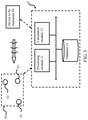
- FIG. 3 is a system architecture diagram showing the power positioning device being positioned of the present invention.
- FIG. 4 illustrates a flowchart of the power positioning method of the present invention
- FIGS. 5A-5B are base to FIG. 4 to illustrate schematic diagrams of the concentric circles of the power positioning method under different transmission powers of the present invention
- FIG. 5C is base to FIG. 4 to illustrate a schematic diagram of the triangulation process for the intersection of the power positioning method of the present invention.
- FIG. 5D is base to FIG. 4 to illustrate a schematic diagram of finding the smallest concentric circle according to the power positioning method of the present invention.
- FIG. 1 Please first refer to FIG. 1 for a system architecture diagram showing configuration of a power positioning device of the present invention.
- a power positioning device 1 includes a processing module 11 , a database 12 and a calculation module 13 electrically connected to each other.
- the power positioning device 1 is used to find a device location of a device to be measured 40 in a space by using a known location device 50 (as shown in FIG. 3 ).
- the power positioning device 1 can also use a test transmitting device 20 and a receiving device 30 to create the required data, but the present invention is not limited thereto. Specifically, all the test transmitting device 20 , receiving device 30 , the device to be measured 40 and the known location device 50 can send and receive wireless signals.
- the wireless signals can be Bluetooth signals
- the test transmitting device 20 , the receiving device 30 , the device to be measured 40 , and the known location device 50 can be the same or different home appliances, computer equipment or mobile devices, etc., but the present invention is not limited thereto.
- each module in the power positioning device 1 may be configured as a hardware device, software program in combination with hardware device, or firmware in combination with hardware device.
- a computer program product may be stored in a computer readable medium and read and executed to achieve the functions of the present invention, and may also be configured in a cloud environment or a virtual server.
- the present invention is not limited in the manner described above. Additionally, the preferred embodiment of the present invention described here is only illustrative. To avoid redundancy, all the possible combinations of changes are not documented in detail. However, it shall be understood by those skilled in the art that each of the modules or elements described above may not be necessary. For the implementation of the present invention, the present invention may also contain other detailed, conventional modules or elements.
- the processing module 11 , database 12 or calculation module 13 can be provided on the same device or separately in different devices, or can be provided in any of the test transmitting device 20 , the receiving device 30 , the device to be measured 40 or the known location device 50 , but the present invention is not limited thereto.
- the processing module 11 sets a plurality of transmission powers of the test transmitting device 20 , so the test transmitting device 20 can emit a plurality of test signals. Then, the receiving device 30 receives the plurality of test signals at a plurality of corresponding distances from the test transmitting device 20 , for example, at a distance of 10 cm, 20 cm, or a distance between 1 m and 6 m, and transmits different test signals with different transmission powers.
- the processing module 11 detects intensities of a plurality of test signals received by the receiving device 30 and records the intensities of the plurality of test signals and the plurality of corresponding distances to the database 12 .
- the calculation module 13 calculates the signal intensity-distance function and signal intensity-distance standard deviation function from the numerical calculation of database 12 , and stores them in the database 12 .
- FIG. 2 a flowchart showing steps of a data setting process in the present invention. It should be noted here that although the following uses the above power positioning device 1 as an example to illustrate the data setting process of the present invention, the data setting process of the present invention is not limited to the power positioning device 1 used in the same structure described above.
- Step 201 Setting a plurality of transmission powers of a test transmitting device, and causing the test transmitting device to transmit a plurality of test signals to a receiving device under a plurality of corresponding distances.
- the processing module 11 sets a plurality of transmission powers of the test transmitting device 20 . Therefore, the test transmitting device 20 can emit a plurality of test signals. Then, the receiving device 30 is allowed to receive the plurality of test signals at a plurality of corresponding distances from the test transmitting device 20 , for example, at a distance of 10 cm, 20 cm, or a different distance between 1 m and 6 m.
- Step 202 Detecting intensities of the plurality of test signals received by the receiving device.
- the processing module 11 detects signal intensities of all signals received by the receiving device 30 .
- Step 203 Recording intensities of the plurality of test signals and the plurality of corresponding distances to the database.
- the processing module 11 stores the signal intensities of all test signals received by the receiving device 30 and the corresponding distances of the test signals into the database 12 .
- Step 204 Calculating and storing a signal intensity-distance function and a signal intensity-distance standard deviation function to the database.
- the calculation module 13 can calculate the signal intensity-distance function and signal intensity-distance standard deviation function for each different transmission power to know the relationship between the signal intensity received by the receiving device 30 and the test transmitting device 20 and the standard deviation. Then, the calculation module 13 can store the functions in the database 12 . In this way, the data setting process of the present invention can be completed.
- FIG. 3 a system architecture diagram of a power positioning device performing positioning of the present invention.
- the power positioning device 1 can use a known location device 50 to find out a device location of the device to be measured 40 in a space.
- a known location device 50 can be used to find out a device location of the device to be measured 40 in a space.
- the present invention does not limit the data setting process to be performed every time to re-establish the signal intensity-distance function and signal intensity-distance standard deviation function in the database 12 .
- the signal intensity-distance function and signal intensity-distance standard deviation function can be preset to the device to be measured 40 or the known location device 50 .
- the processing module 11 controls the device to be measured 40 to emit a plurality of positioning signals at a plurality of transmission powers, such that the plurality of known location devices 50 receive the plurality of positioning signals, and record the intensities of the plurality of positioning signals, a plurality of corresponding receiving time and the locations of the plurality of known location devices 50 to the database 12 .
- the plurality of known location devices 50 also receive an identification code of the device to be measured 40 , thereby identifying the device to be measured 40 . This identification code will also be stored in the database 12 .
- the processing module 11 finds out a device with the larger signal intensity in the received plurality of positioning signals, such as the known location devices 51 , 52 , 53 .
- the calculation module 13 can find out the device location of device to be measured 40 according to the signal intensity-distance function and the signal intensity-distance standard deviation function from the locations of the known location devices 51 , 52 , 53 .
- FIG. 4 related to a flowchart showing steps of a device positioning process of the present invention.
- Step 401 Controlling the device to be measured to transmit a plurality of positioning signals with a plurality of transmission powers to cause a plurality of known location devices to receive the plurality of positioning signals.
- the processing module 11 first controls the device to be measured 40 to transmit positioning signals with different transmission powers.
- the different known location device 50 can receive the positioning signal of the device to be measured 40 .
- the plurality of known location devices 50 also receive an identification code of the device to be measured 40 .
- Step 402 Recording the plurality of positioning signal intensities, a plurality of corresponding receiving time, and coordinates of the plurality of known location devices.
- the known location device 50 Since the device to be measured 40 transmits positioning signals with different transmission powers, after the known location device 50 receives the positioning signal, the known location device 50 sends all the positioning signals, the corresponding receiving time and coordinates of the known location device 50 back to the database 12 .
- Step 403 Finding out the known location device with a larger signal intensity among the received plurality of positioning signals.
- the processing module 11 finds out the known location devices 51 , 52 , 53 in a plurality of positioning signals that have received a larger signal intensity.
- Step 404 Grouping according to a plurality of power, setting a plurality of the known location devices as the circle center, using the signal intensity-distance function to get the distance, using the distance deviation function to get the standard deviation to draw a plurality of circles, and obtaining a plurality of intersections between the circles.
- the calculation module 13 can query the signal intensity-distance function and the signal intensity-distance standard deviation function according to the plurality of positioning signal intensity s, the plurality of corresponding receiving time and the known location device with the larger intensity.
- the known location devices 51 , 52 , 53 at different powers are grouped, the fixed point coordinates of the known location devices 51 , 52 , 53 are taken as the center of the circle, and the distance under this signal intensity according to the signal intensity-distance function can be obtained, that is, the distance is set as the base radius.
- the signal intensity-distance standard deviation function is used to find out the distance standard deviation under the signal intensity, that is, the standard deviation is set as the basis for radius adjustment.
- FIGS. 5A-5B are base to FIG. 4 , to illustrate schematic diagrams of the concentric circles of the power positioning method under different transmission powers of the present invention.
- a plurality of circles with the fixed point coordinates of the known location devices 51 , 52 , 53 are drawn as the center, and the fixed points are used to find out the intersection.
- the original radius distance minus 0.67 standard deviation is set as the minimum radius
- the original radius distance plus 0.67 standard deviation is set as the maximum radius. If the two circles are tangent or intersect, it can be ended.
- FIG. 5B is a schematic diagram of the intersection calculated by known location devices 51 , 52 , 53 at another power. Accordingly, in FIG. 5B , six intersections g-l of known location device 51 , 52 , 53 at another power can be obtained.
- Step 405 Performing a triangulation process on the plurality of intersections to obtain a plurality of triangles.
- FIG. 5C is base to FIG. 4 , to illustrate a schematic diagram of the triangulation process for the intersection of the power positioning method of the present invention.
- the calculation module 13 removes outliers of all the intersections a-l and performs a Drouin triangulation process to obtain a plurality of triangles.
- 12 intersections a-l obtained from two different powers are used for calculation, but the present invention is not limited thereto. More intersections can get more accurate results.
- Step 406 Finding out the triangle with the smallest circumscribed circle radius among the plurality of triangles to set the center of the circumscribed circle to be the device location of the device to be measured.
- FIG. 5D is base to FIG. 4 , to illustrate a schematic diagram of finding the smallest concentric circle according to the power positioning method of the present invention.
- the calculation module 13 finds out the center of the smallest circumscribed circle in the triangle with the smallest circumscribed circle radius.
- the coordinate of the device to be measured 40 can be obtained by setting the center of the smallest circumscribed circle to be the device location 41 of the device to be measured 40 . Taking FIG. 5D as an example, it can be obtained that the triangle formed by intersection i, h, k is the triangle with the smallest circumscribed circle radius. Therefore, the coordinate of the center of the circumscribed circle is the device location 41 .
- the power positioning method of the present invention is not limited to the above order of steps. As long as the objective of the present invention can be achieved, the order of the above steps can also be changed.
- the position of device to be measured 40 can be effectively found without too many additional sensing modules.
Landscapes
- Engineering & Computer Science (AREA)
- Computer Networks & Wireless Communication (AREA)
- Signal Processing (AREA)
- Physics & Mathematics (AREA)
- Electromagnetism (AREA)
- Quality & Reliability (AREA)
- Position Fixing By Use Of Radio Waves (AREA)
Abstract
Description
Claims (12)
Priority Applications (1)
| Application Number | Priority Date | Filing Date | Title |
|---|---|---|---|
| US17/074,915 US11265677B2 (en) | 2019-12-24 | 2020-10-20 | Power positioning method and power positioning device thereof |
Applications Claiming Priority (2)
| Application Number | Priority Date | Filing Date | Title |
|---|---|---|---|
| US201962953248P | 2019-12-24 | 2019-12-24 | |
| US17/074,915 US11265677B2 (en) | 2019-12-24 | 2020-10-20 | Power positioning method and power positioning device thereof |
Publications (2)
| Publication Number | Publication Date |
|---|---|
| US20210195369A1 US20210195369A1 (en) | 2021-06-24 |
| US11265677B2 true US11265677B2 (en) | 2022-03-01 |
Family
ID=76439021
Family Applications (1)
| Application Number | Title | Priority Date | Filing Date |
|---|---|---|---|
| US17/074,915 Expired - Fee Related US11265677B2 (en) | 2019-12-24 | 2020-10-20 | Power positioning method and power positioning device thereof |
Country Status (1)
| Country | Link |
|---|---|
| US (1) | US11265677B2 (en) |
Citations (10)
| Publication number | Priority date | Publication date | Assignee | Title |
|---|---|---|---|---|
| US20040203904A1 (en) | 2002-12-27 | 2004-10-14 | Docomo Communications Laboratories Usa, Inc. | Selective fusion location estimation (SELFLOC) for wireless access technologies |
| US20070258421A1 (en) * | 2006-05-08 | 2007-11-08 | Farshid Alizadeh-Shabdiz | Estimation of position using WLAN access point radio propagation characteristics in a WLAN positioning system |
| JP2010239331A (en) | 2009-03-31 | 2010-10-21 | Advanced Telecommunication Research Institute International | Owner identification system |
| EP2469298A1 (en) | 2010-12-23 | 2012-06-27 | Televic Healthcare NV | Method and device for determining location of a target |
| US20130178235A1 (en) * | 2012-01-06 | 2013-07-11 | Chien-Sheng Chen | Wireless Communication Positioning Method |
| US20170356979A1 (en) * | 2016-06-13 | 2017-12-14 | Kabushiki Kaisha Toshiba | Indoor localization using received signal quality weights |
| US20180213356A1 (en) | 2016-11-14 | 2018-07-26 | Suresh Kumar Singamsetty | Prediction algorithm for location estimation |
| TWI675215B (en) | 2018-08-16 | 2019-10-21 | 恆準定位股份有限公司 | Indoor positioning system |
| US20190331760A1 (en) | 2017-01-20 | 2019-10-31 | Murata Manufacturing Co., Ltd. | Position detection system |
| US10484820B2 (en) | 2016-03-23 | 2019-11-19 | Fedex Corporate Services, Inc. | Methods and systems for container node-based enhanced management of a multi-level wireless node network |
-
2020
- 2020-10-20 US US17/074,915 patent/US11265677B2/en not_active Expired - Fee Related
Patent Citations (11)
| Publication number | Priority date | Publication date | Assignee | Title |
|---|---|---|---|---|
| US20040203904A1 (en) | 2002-12-27 | 2004-10-14 | Docomo Communications Laboratories Usa, Inc. | Selective fusion location estimation (SELFLOC) for wireless access technologies |
| US20070258421A1 (en) * | 2006-05-08 | 2007-11-08 | Farshid Alizadeh-Shabdiz | Estimation of position using WLAN access point radio propagation characteristics in a WLAN positioning system |
| JP2010239331A (en) | 2009-03-31 | 2010-10-21 | Advanced Telecommunication Research Institute International | Owner identification system |
| EP2469298A1 (en) | 2010-12-23 | 2012-06-27 | Televic Healthcare NV | Method and device for determining location of a target |
| US20130178235A1 (en) * | 2012-01-06 | 2013-07-11 | Chien-Sheng Chen | Wireless Communication Positioning Method |
| TW201329485A (en) | 2012-01-06 | 2013-07-16 | Novatek Microelectronics Corp | Wireless communication positioning method |
| US10484820B2 (en) | 2016-03-23 | 2019-11-19 | Fedex Corporate Services, Inc. | Methods and systems for container node-based enhanced management of a multi-level wireless node network |
| US20170356979A1 (en) * | 2016-06-13 | 2017-12-14 | Kabushiki Kaisha Toshiba | Indoor localization using received signal quality weights |
| US20180213356A1 (en) | 2016-11-14 | 2018-07-26 | Suresh Kumar Singamsetty | Prediction algorithm for location estimation |
| US20190331760A1 (en) | 2017-01-20 | 2019-10-31 | Murata Manufacturing Co., Ltd. | Position detection system |
| TWI675215B (en) | 2018-08-16 | 2019-10-21 | 恆準定位股份有限公司 | Indoor positioning system |
Also Published As
| Publication number | Publication date |
|---|---|
| US20210195369A1 (en) | 2021-06-24 |
Similar Documents
| Publication | Publication Date | Title |
|---|---|---|
| EP3842820B1 (en) | Power positioning method and power positioning device | |
| CN103560813B (en) | Mobile terminal positioning method and device based on Bluetooth technology | |
| US8918118B2 (en) | Method, apparatus and system for addressing operating devices for luminaires | |
| US20170195936A1 (en) | Cloud-coordinated location system using ultrasonic pulses and radio signals | |
| CN105607034A (en) | Three-dimensional space detection system, positioning method and system | |
| CN111829525A (en) | UWB indoor and outdoor integrated intelligent navigation and positioning method and system | |
| CN108917762B (en) | Method and system for positioning electric appliance, storage medium and home system | |
| EP3835808B1 (en) | Dynamic power positioning method and dynamic power positioning system | |
| WO2019052575A1 (en) | Method, apparatus and device for positioning wireless device, and storage medium | |
| CN113390433A (en) | Robot positioning method and device, robot and storage medium | |
| US11265677B2 (en) | Power positioning method and power positioning device thereof | |
| US11553451B2 (en) | Two-way signal positioning method and two-way signal positioning system thereof | |
| US11454695B2 (en) | Dynamic power positioning method and dynamic power positioning system thereof | |
| US12360195B2 (en) | Method and system for wireless positioning | |
| CN113050033B (en) | Power positioning method and power positioning device | |
| CN113009415B (en) | Dynamic power positioning method and dynamic power positioning system thereof | |
| US12253615B2 (en) | Beacon map construction method, device, and computer-readable storage medium | |
| CN114487997B (en) | Relative position positioning system and relative position positioning method thereof | |
| CN204777030U (en) | A reputation combination positioning system for warehouse system | |
| CN110809239A (en) | Pipe gallery personnel positioning method, server and system | |
| CN112304335B (en) | Hydraulic support tilt sensor calibration method and system | |
| CN108933701A (en) | A kind of data center server localization method and equipment | |
| CN115717857A (en) | Device and method for detecting relative position of object | |
| CN114201979A (en) | Robot positioning method and device | |
| CN116074948A (en) | A positioning method, device and computer-readable storage medium |
Legal Events
| Date | Code | Title | Description |
|---|---|---|---|
| AS | Assignment |
Owner name: GUNITECH CORP., TAIWAN Free format text: ASSIGNMENT OF ASSIGNORS INTEREST;ASSIGNORS:TSENG, YU-CHEE;CHIANG, TING-HUI;HUANG, KAI-CHENG;AND OTHERS;SIGNING DATES FROM 20200818 TO 20200911;REEL/FRAME:054108/0112 |
|
| FEPP | Fee payment procedure |
Free format text: ENTITY STATUS SET TO UNDISCOUNTED (ORIGINAL EVENT CODE: BIG.); ENTITY STATUS OF PATENT OWNER: SMALL ENTITY |
|
| FEPP | Fee payment procedure |
Free format text: ENTITY STATUS SET TO SMALL (ORIGINAL EVENT CODE: SMAL); ENTITY STATUS OF PATENT OWNER: SMALL ENTITY |
|
| STPP | Information on status: patent application and granting procedure in general |
Free format text: DOCKETED NEW CASE - READY FOR EXAMINATION |
|
| STPP | Information on status: patent application and granting procedure in general |
Free format text: NON FINAL ACTION MAILED |
|
| STPP | Information on status: patent application and granting procedure in general |
Free format text: RESPONSE TO NON-FINAL OFFICE ACTION ENTERED AND FORWARDED TO EXAMINER |
|
| STPP | Information on status: patent application and granting procedure in general |
Free format text: NOTICE OF ALLOWANCE MAILED -- APPLICATION RECEIVED IN OFFICE OF PUBLICATIONS |
|
| STCF | Information on status: patent grant |
Free format text: PATENTED CASE |
|
| FEPP | Fee payment procedure |
Free format text: MAINTENANCE FEE REMINDER MAILED (ORIGINAL EVENT CODE: REM.); ENTITY STATUS OF PATENT OWNER: SMALL ENTITY |
|
| LAPS | Lapse for failure to pay maintenance fees |
Free format text: PATENT EXPIRED FOR FAILURE TO PAY MAINTENANCE FEES (ORIGINAL EVENT CODE: EXP.); ENTITY STATUS OF PATENT OWNER: SMALL ENTITY |
|
| STCH | Information on status: patent discontinuation |
Free format text: PATENT EXPIRED DUE TO NONPAYMENT OF MAINTENANCE FEES UNDER 37 CFR 1.362 |