US11263878B2 - Phase computing device, phase computing method, haptic presentation system, and program - Google Patents
Phase computing device, phase computing method, haptic presentation system, and program Download PDFInfo
- Publication number
- US11263878B2 US11263878B2 US16/637,566 US201816637566A US11263878B2 US 11263878 B2 US11263878 B2 US 11263878B2 US 201816637566 A US201816637566 A US 201816637566A US 11263878 B2 US11263878 B2 US 11263878B2
- Authority
- US
- United States
- Prior art keywords
- phase
- vibrator
- computing device
- wave motion
- interference
- Prior art date
- Legal status (The legal status is an assumption and is not a legal conclusion. Google has not performed a legal analysis and makes no representation as to the accuracy of the status listed.)
- Active
Links
Images


Classifications
-
- G—PHYSICS
- G08—SIGNALLING
- G08B—SIGNALLING OR CALLING SYSTEMS; ORDER TELEGRAPHS; ALARM SYSTEMS
- G08B6/00—Tactile signalling systems, e.g. personal calling systems
-
- G—PHYSICS
- G06—COMPUTING OR CALCULATING; COUNTING
- G06F—ELECTRIC DIGITAL DATA PROCESSING
- G06F3/00—Input arrangements for transferring data to be processed into a form capable of being handled by the computer; Output arrangements for transferring data from processing unit to output unit, e.g. interface arrangements
- G06F3/01—Input arrangements or combined input and output arrangements for interaction between user and computer
- G06F3/016—Input arrangements with force or tactile feedback as computer generated output to the user
-
- G—PHYSICS
- G10—MUSICAL INSTRUMENTS; ACOUSTICS
- G10K—SOUND-PRODUCING DEVICES; METHODS OR DEVICES FOR PROTECTING AGAINST, OR FOR DAMPING, NOISE OR OTHER ACOUSTIC WAVES IN GENERAL; ACOUSTICS NOT OTHERWISE PROVIDED FOR
- G10K9/00—Devices in which sound is produced by vibrating a diaphragm or analogous element, e.g. fog horns, vehicle hooters or buzzers
- G10K9/12—Devices in which sound is produced by vibrating a diaphragm or analogous element, e.g. fog horns, vehicle hooters or buzzers electrically operated
- G10K9/13—Devices in which sound is produced by vibrating a diaphragm or analogous element, e.g. fog horns, vehicle hooters or buzzers electrically operated using electromagnetic driving means
Definitions
- the present technology relates to, for example, a phase computing device, a phase computing method, a haptic presentation system, and a program, which are capable of forming an ultrasonic interference pattern with an optional shape.
- the ultrasonic spatial haptic presentation device includes several tens to several hundreds of ultrasonic vibrators disposed in an array, forms mutually strengthening points and lines on a space by interference of ultrasonic waves emitted by the individual vibrators, and presents haptic feedback to the air by an acoustic radiation pressure thereof.
- Patent Literature 1 discloses a tactile device that controls the phase of ultrasonic waves, which are emitted by ultrasonic wave generation elements arranged one- or two-dimensionally, for each of the elements, to achieve a desired sound pressure distribution in an arrangement direction of the elements.
- Patent Literature 1 Japanese Patent Application Laid-open No. 2003-29898
- the interference of the opposite phase may occur, in which ultrasonic waves interfering at a certain point cancel out the acoustic radiation pressure of a different interference point. This makes it difficult to form an ultrasonic interference pattern with a desired optional shape.
- phase computing device a phase computing method, a haptic presentation system, and a program, which are capable of forming an ultrasonic interference pattern with an optional shape.
- a phase computing device including a coordinate determination unit and a computing unit.
- the coordinate determination unit determines space coordinates at which an interference pattern of wave motion emitted from a vibrator phased array is to be presented, the wave motion including ultrasonic waves, electromagnetic waves, or other waves.
- the computing unit calculates an initial phase of each vibrator, a sum of energy densities of the wave motion at respective points of the space coordinates being maximum in the initial phase.
- the computing unit calculates the initial phase of each vibrator of the ultrasonic vibrator array, in which the sum of the energy densities of the wave motion at the respective points on the space is maximum, an interference pattern being to be presented at the respective points. Accordingly, the interference pattern of the wave motion with an optional shape can be formed.
- the computing unit may be configured to generate an evaluation function indicating a correlation between the sum of the energy densities of the wave motion at the respective points of the space coordinates and the initial phase of each vibrator, and to calculate an optimum solution of the initial phase of each vibrator, the evaluation function being made maximum or maximal by the optimum solution.
- the computing unit may be configured to perform iterative computation of a recurrence formula of a gradient descent, to cause a computed value to converge to the optimum solution, the recurrence formula being obtained by differentiating the evaluation function.
- the computing unit may be configured to calculate a step coefficient, the step coefficient being obtained by dividing a predetermined constant by the number of points constituting the space coordinates, and to perform iterative computation of the recurrence formula with the step coefficient being as an update width for each step.
- the computing unit may be configured to execute, in a case where a computation result of the recurrence formula is smaller than a last computation result, processing of decreasing the step coefficient.
- the computing unit may be configured to output, in a case where a difference between a computation result of the recurrence formula and a last computation result is smaller than a predetermined threshold, a current computation result as the optimum solution.
- the computing unit may be configured to perform iterative computation of a recurrence formula, to cause a computed value to converge to the optimum solution, the recurrence formula being obtained by dividing a derivative term of the evaluation function at each point of the space coordinates by the ultrasonic energy density of the wave motion at the point.
- the computing unit may be configured to divide, in a case where the ultrasonic energy density at each point is a value of 0 or close to 0, the derivative term with the energy density of the wave motion being set to be larger than the value in order to avoid diffusion due to the division.
- the computing unit may be configured to initialize, in a calculation of the optimum solution, the initial phase of each vibrator with an identical value.
- the coordinate determination unit may be configured to determine, as the space coordinates, two-dimensional coordinates indicating the interference pattern, and a distance coordinate from the vibrator phased array to a presentation position of the interference pattern.
- the coordinate determination unit may be configured to determine the two-dimensional coordinates on the basis of electronic image data indicating the interference pattern, and to determine three-dimensional coordinates of a haptic pattern together with distance information, the distance information being input in a numerical value.
- a phase computing method including determining space coordinates at which an interference pattern of wave motion emitted from a vibrator phased array is to be presented, the wave motion including ultrasonic waves, electromagnetic waves, or other waves.
- An initial phase of each vibrator is calculated, a sum of energy densities of the wave motion at respective points of the space coordinates being maximum in the initial phase.
- a haptic presentation system including a vibrator phased array, a coordinate determination unit, and a computing unit.
- the coordinate determination unit determines space coordinates at which an interference pattern of wave motion emitted from the vibrator phased array is to be presented, the wave motion including ultrasonic waves, electromagnetic waves, or other waves.
- the computing unit calculates an initial phase of each vibrator, a sum of energy densities of the wave motion at respective points of the space coordinates being maximum in the initial phase.
- the haptic presentation system may further include: an input unit to which information associated with the interference pattern is input; and a detector that detects a position at which the interference pattern is to be presented.
- the coordinate determination unit determines the space coordinates on the basis of an output of the input unit and an output of the detector.
- a program that causes a computer to execute the steps of: determining space coordinates at which an interference pattern of wave motion emitted from a vibrator phased array is to be presented, the wave motion including ultrasonic waves, electromagnetic waves, or other waves; and calculating an initial phase of each vibrator, a sum of energy densities of the wave motion at respective points of the space coordinates being maximum in the initial phase.
- a phase computing device including a coordinate determination unit and a computing unit.
- the coordinate determination unit determines space coordinates at which an interference pattern of electromagnetic waves emitted from a vibrator array is to be presented.
- the computing unit calculates an initial phase of each vibrator, a sum of electromagnetic energy densities at respective points of the space coordinates being maximum in the initial phase.
- FIG. 1 is a schematic configuration diagram showing a haptic presentation system according to an embodiment of the present technology.
- FIG. 2 is a block diagram showing a system configuration of each unit of a haptic presentation system 100 .
- FIG. 3 is a diagram for describing the basic principle of a gradient descent in a case of one variable.
- FIG. 4 is a diagram showing an image of a gradient descent in a case of two variables.
- FIG. 5 shows simulation results showing one action of the haptic presentation system.
- FIG. 6 shows simulation results showing another action of the haptic presentation system.
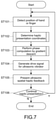
- FIG. 7 is a flowchart showing an example of a processing procedure in the haptic presentation system.
- FIG. 8 is a flowchart showing the details of FIG. 7 .
- FIG. 1 is a schematic configuration diagram showing a haptic presentation system according to an embodiment of the present technology.
- X-, Y-, and Z-axes respectively represent three axes directions orthogonal to one another, and the Z-axis corresponds to an ultrasonic wave emission direction.
- a haptic presentation system 100 of this embodiment includes an ultrasonic vibrator array 10 and a controller 20 .
- the ultrasonic vibrator array 10 is configured by a phased array including a plurality of (N pieces) ultrasonic vibrators, the phases of which are capable of being individually controlled.
- the individual vibrators 11 constituting the ultrasonic vibrator array 10 are typically configured by vibration elements each having an identical structure and are two-dimensionally arranged such that respective ultrasonic wave emission ports are positioned on the identical plane (XY-plane).
- An arrangement form is not particularly limited.
- the individual vibrators 11 are arranged in a grid-like or hexagonal close-packed manner.
- the number of vibrators 11 is also not particularly limited and can be appropriately set depending on specifications or purposes. For example, the number of vibrators 11 is several tens to several hundreds.
- the frequency of ultrasonic waves is also not particularly limited and is typically 20 kHz or more.
- the ultrasonic vibrator array 10 forms mutually strengthening points and lines on a space by interference of ultrasonic waves emitted by the individual vibrators 11 and presents, by using an acoustic radiation pressure (energy density of ultrasonic waves) thereof, haptic feedback to the user's hand and fingers (hereinafter, collectively referred to as hand/finger H), which are positioned on the space.
- acoustic radiation pressure energy density of ultrasonic waves
- the controller 20 is configured to be capable of computing an initial phase of each vibrator 11 , which forms an ultrasonic interference pattern with a desired and optional shape, and capable of driving each vibrator 11 with the calculated initial phase.
- FIG. 2 is a block diagram showing a system configuration of each unit of the haptic presentation system 100 .
- the haptic presentation system 100 further includes a detector 30 and an input unit 40 .
- the detector 30 detects a position at which an ultrasonic interference pattern is to be presented (a position of the hand/finger H of the user, positioned immediately above the ultrasonic vibrator array 10 ). Typically, the detector 30 detects two-dimensional coordinates (X and Y coordinates) obtained by projecting the shape of the hand/finger H on the ultrasonic vibrator array, and distance information (Z coordinate) corresponding to the height from the ultrasonic wave emission surface of the ultrasonic vibrator array 10 to the hand/finger H.
- the detector 30 may be configured integrally with the ultrasonic vibrator array 10 or configured as a part of the ultrasonic vibrator array 10 .
- the configuration of the detector 30 is not particularly limited, and ranging sensors such as a TOF (Time of Flight)-type or phase-difference-type laser displacement gauge, and imagers such as an infrared ray camera can be employed.
- the detector 30 is configured to output the detected measured value to the controller 20 .
- the detector 30 may output acquired data such as image information directly to the controller 20 . In this case, coordinate information of the hand/finger H is extracted in the controller 20 on the basis of the acquired data.
- the height position of the hand/finger H to be detected by the detector 30 may be one point or a plurality of points. In a case where one point is detected, for example, the center portion of the palm of the hand/finger H is detected as a representative value. In a case where a plurality of points is detected, for example, the height position of the palm of the hand/finger H and/or each finger is detected.
- the input unit 40 includes an input device capable of inputting information (such as shape) associated with the ultrasonic interference pattern to be presented to the hand/finger H.
- the input unit 40 may be configured integrally with the controller 20 or may be configured as a part of the controller 20 .
- the pattern shape typically includes a two-dimensional image of the XY coordinate system or a three-dimensional image of the XYZ coordinate system.
- a scanning device that electronically takes in prepared images, a drawing device including a drawing tool, and an input device including a GUI (Graphic User Interface) to be operated for input by a user can be used.
- the pattern shape may be image data having a shape optionally selected from a plurality of shapes prepared in advance.
- the image data is transmitted, as appropriate electronic image data such as bitmap data or CAD data, to the controller 20 .
- the number of pixels or the number of bits of the image data is not particularly limited and can be appropriately set according to the number of vibrators constituting the ultrasonic vibrator array 10 , or the like.
- the controller 20 includes a phase computing device 50 and a drive unit 60 .
- the phase computing device 50 is configured by a computer and includes a CPU 51 , a storage unit 52 , a RAM (Random Access Memory) 53 , an I/O (Input/Output) port 54 , and the like.
- the CPU 51 includes a coordinate determination unit 511 and a computing unit 512 .
- the coordinate determination unit 511 determines space coordinates at which an interference pattern of ultrasonic waves emitted from the ultrasonic vibrator array 10 is to be presented.
- the coordinate determination unit 511 determines the space coordinates on the basis of the outputs of the detector 30 and the input unit 40 , which are input via the I/O port 54 .
- the coordinate determination unit 511 determines, as the space coordinates, three-dimensional coordinates (X, Y, Z) indicating an interference pattern, by an input operation of the user or computation.
- the three-dimensional coordinates described above are determined on the basis of the output of the input unit 40 .
- the coordinates described above are determined on the basis of two-dimensional (X, Y) or three-dimensional (X, Y, Z) electronic data (such as bitmap or CAD data) input from the input unit 40 .
- a distance coordinate (Z) from the ultrasonic vibrator array 10 to an interference pattern presentation position is input in a numerical value via the input unit 40 .
- the computing unit 512 computes the initial phases of the individual vibrators 11 of the ultrasonic vibrator array 10 by using a predetermined algorithm to be described later.
- the computing unit 512 outputs information (initial phase data) regarding the computed initial phases of the respective vibrators 11 to the drive unit 60 via the I/O port 54 .
- the storage unit 52 includes, for example, an information storage device such as an HDD (Hard Disk Drive) or SSD (Solid State Drive) and stores various programs to be executed in the CPU 51 , parameters, and the like.
- the programs and the like stored in the storage unit 52 are read when the CPU 51 executes various types of processing, and are decompressed in the RAM 53 .
- the programs are installed in, for example, the phase computing device 50 via various recording media. Alternatively, the programs may be installed via the Internet or the like. As will be described later, the programs cause the controller 20 (phase computing device 50 ) to execute the step of determining space coordinates at which an interference pattern of ultrasonic waves emitted from the ultrasonic vibrator array 10 is to be presented, and the step of calculating an initial phase of each vibrator 11 , the sum of ultrasonic energy densities at respective points of the space coordinates described above being maximum in the initial phase.
- the drive unit 60 includes an I/O port 61 , a signal generation circuit 62 , amplifiers 63 , and buffers 64 .
- the drive unit 60 receives initial phase data, which is generated in the phase computing device 50 , via the I/O port 61 .
- the signal generation circuit 62 is a circuit that generates a pulse width modulation signal for driving each vibrator 11 of the ultrasonic vibrator array 10 on the basis of the initial phase data and includes, for example, FPGA (Field Programmable Gate Array).
- the pulse width modulation signal is individually generated for each vibrator 11 .
- Each signal is amplified by the amplifier 63 , a voltage thereof is corrected by the buffer 64 , and the resultant signal is output, as a drive signal, to the ultrasonic vibrator array 10 .
- the ultrasonic vibrator array 10 drives each vibrator 11 on the basis of the drive signal described above. Accordingly, an ultrasonic interference pattern having a maximum ultrasonic energy density at the position and in the shape specified by the user is formed, and a spatial haptic pattern corresponding to an acoustic radiation pressure thereof is presented to the user.
- a distance from the point to each vibrator is divided by the wavelength of the ultrasonic waves, and the phase of the remainder portion of the wavelength is adjusted for each of the individual vibrators, thus enabling the spatial haptic feedback to be presented.
- a distance from an optional point, at which spatial haptic feedback is intended to be presented, to an i-th vibrator is represented by ri
- the wavelength of the ultrasonic waves is represented by ⁇
- a modulo function is represented by MOD
- the following initial phase ⁇ i is added to the i-th vibrator, thus enabling the spatial haptic feedback to be relatively easily achieved.
- ⁇ i (2 ⁇ / ⁇ )MOD( ri / ⁇ )[rad]
- an existing ultrasonic simulator can calculate an interference pattern.
- an input phase for forming a desired interference pattern is known. Therefore, in a case where an unknown input phase for forming a particular interference pattern is intended to be obtained, it is necessary to confirm an interference pattern after inputting options of the phase and executing computation. If the desired interference pattern is not obtained, it is necessary to input options of a different phase again and reexecute computation. If such iterative computation is automated, the amount of computation increases, and it will take a considerable amount of time to perform computation until an optimum solution is obtained.
- the phase computing device 50 (computing unit 512 ) of this embodiment is configured to calculate an initial phase of each vibrator 11 that has a maximum sum of ultrasonic energy densities at respective points of space coordinates at which an interference pattern of ultrasonic waves is to be presented.
- the initial phase of each vibrator 11 that has a maximum sum of energy densities means an initial phase of each vibrator that gives a theoretically maximum value or maximal value regarding the sum of ultrasonic energy densities at the respective points of the space coordinates described above.
- the theoretically maximum value means a maximum value of interference waves, which is expressed by adding functions together in a case where wave motions generated by the individual vibrators constituting the phased array are expressed using an exponential function or a trigonometric function.
- the theoretically maximal value similarly means a maximal value of interference waves.
- phase computing device 50 (computing unit 512 )
- the phase computing device 50 (computing unit 512 ) is configured to generate an evaluation function, which indicates a correlation between the sum of ultrasonic energy densities at respective points of space coordinates at which an interference pattern of ultrasonic waves is to be presented, and the initial phase of each vibrator 11 , and is configured to calculate an optimum solution of the initial phase of each vibrator 11 , by which the evaluation function is made maximum or maximal.
- the sum (Esum) of ultrasonic energy densities at respective (X, Y, Z) points in a space haptic pattern is used.
- the phase computing device 50 (computing unit 512 ) is configured to perform iterative computation of a recurrence formula of gradient descent to cause a computed value to converge to the optimum solution.
- the recurrence formula is obtained by differentiating the evaluation function described above.
- the iterative computation of the recurrence formula based on the gradient descent allows calculation of the initial phase of the individual vibrator 11 , which maximizes the ultrasonic energy densities at an optional position specified by the user (in this example, the position of the hand/finger H) and in the shape specified by the user.
- the phase computing device 50 (computing unit 512 ) is configured to perform iterative computation of a recurrence formula, which is obtained by dividing a derivative term of the evaluation function at each point of the space coordinates by an ultrasonic energy density of the point, to cause a computed value to converge to the optimum solution.
- the derivative term at each of (X, Y, Z) points in the space haptic pattern is divided by the ultrasonic energy density (E X, Y, Z ) at each of the (X, Y, Z) points and is weighted, and thus the distribution of the ultrasonic energy density (E X, Y, Z ) can be smoothed.
- the phase computing device 50 executes the above-mentioned computation with E X, Y, Z being set to a larger value in order to avoid diffusion due to the division.
- the phase computing device 50 executes the above-mentioned computation with E X, Y, Z being set to 1.
- the case where the value of the ultrasonic energy density (E X, Y, Z ) is close to 0 means that the value of the ultrasonic energy density (E X, Y, Z ) is substantially 0, and, herein, means 0 or more and smaller than 1.
- the phase computing device 50 (computing unit 512 ) is configured to calculate a step coefficient, which is obtained by dividing a predetermined constant by the number of points constituting the space coordinates described above, and is configured to perform iterative computation of the above-mentioned recurrence formula with the step coefficient being used as an update width for each step.
- step coefficient a value obtained by dividing a predetermined constant “a” by the number of (X, Y, Z) points in the space haptic pattern is used as the coefficient (hereinafter, referred to as step coefficient) ⁇ , which determines an update width of the initial phase for each step of the recurrence formula.
- the phase computing device 50 (computing unit 512 ) initializes, when the iterative computation is started in the calculation of an optimum solution, the initial phase of each vibrator 11 with an identical value.
- the initial phases of all the vibrators 11 are initialized with an identical value.
- the phase computing device 50 (computing unit 512 ) is configured to executes, in a case where a computation result of the above-mentioned recurrence formula is smaller than the last computation result, processing of decreasing the step coefficient described above.
- n step the sum (Esum) of ultrasonic energy densities decreases in the computation from the n-th step (hereinafter, also referred to as n step) to the (n+1)-th step (hereinafter, also referred to as (n+1) step)
- a computation result of the (n+1)-th step is not employed.
- the computation of the (n+1)-th step is performed again with the step coefficient ⁇ being set to (1/2) ⁇ , for example.
- a decrease rate of the step coefficient ⁇ is not limited to 1 ⁇ 2 and can be set to an appropriate value.
- the phase computing device 50 (computing unit 512 ) is configured to output a current computation result as the optimum solution, in a case where a difference between the computation result of the above-mentioned recurrence formula and the last computation result is smaller than a predetermined threshold.
- the computation in the iterative computation of the recurrence formula by the gradient descent, the computation is configured to be terminated in a case where a difference between the computation results from the n-th step to the (n+1)-th step is smaller than a predetermined threshold Th.
- phase computing device 50 Subsequently, the details of the phase computing device 50 will be described together with the basic principle.
- a sound pressure P of ultrasonic waves at an optional point in an upper space of the phased array including N ultrasonic vibrators is described by the following expression (1)
- t represents a time
- r represents a vector indicating an optional point
- ⁇ represents a vector including components of initial phases ⁇ 1 to ⁇ N of N vibrators
- ⁇ represents the number of angular vibrations of ultrasonic waves
- r i represents a distance from the i-th (1 ⁇ i ⁇ N) vibrator to an optional point among the N vibrators forming the phased array
- ⁇ i represents an initial phase of the i-th vibrator
- P i represents an amplitude of ultrasonic waves generated by the i-th vibrator
- j represents an imaginary unit.
- the energy density E of ultrasonic waves at a point r is proportional to the square of the amplitude (maximum sound pressure) P and is given by the following expression (4).
- ⁇ represents a reflection coefficient of ultrasonic waves (at the interface between air and skin, ⁇ 2)
- p represents the density of air
- c represents a sonic speed.
- the strength of spatial haptic feedback which is sensed by a human via ultrasonic waves, is considered to be proportional to the energy density (acoustic radiation pressure) E. Therefore, in order to present spatial haptic feedback with a particular shape through ultrasonic waves, it is only necessary to calculate such an initial phase that maximizes the energy density E at each point of that shape.
- the energy density E at the point r is expressed by a function of an initial phase vector ⁇ of the N vibrators.
- approximate solutions of the components ⁇ 1 to ⁇ N of the initial phase vector ⁇ that maximizes the energy density E are obtained by a numerical calculation using the computer.
- a gradient method other than the gradient descent or a numerical calculation approach such as Newton's method may be used if the approximate solutions of the initial phase ⁇ 1 to ⁇ N are obtained.
- the gradient descent is an approach of obtaining a minimal value or maximal value of a certain function ⁇ (x) by a numerical calculation using the computer.
- the gradient descent is used in a case where a minimal value of energy or the like is obtained by a numerical calculation in a physical simulation, and is thus called a “descent” method.
- the gradient descent can obtain a maximal value as will be described later.
- This embodiment uses gradient descent aiming at obtaining a phase that maximizes an acoustic radiation pressure of ultrasonic waves (energy density of sonic waves).
- FIG. 3 shows the basic principle of the gradient descent in a case of one variable.
- a function ⁇ (x) is given, and x, by which a maximal value of the function ⁇ (x) is given, is obtained by the gradient descent, first, an initial value x 0 of x is properly determined.
- a first-order differentiation df(x 0 )/dx of x 0 is calculated and added to x 0 to obtain x 1 .
- FIG. 4 shows an image of the gradient descent in the case of two variables.
- Derivative terms of the expressions (a) and (b) are respectively an x component and a y component of a vector ( ⁇ (x n , y n )) in a direction in which the gradient is maximum at x n and y n , and x n+1 and y n+1 are points that proceed by the magnitude of the gradient in that direction, with x n and y n being as starting points.
- the expression (5) shows a recurrence formula of the gradient descent obtained from the expression (4).
- [Math. 5] ⁇ [ n+ 1] ⁇ [ n ]+ ⁇ E ( r , ⁇ [ n ]) (5)
- ⁇ is a vector including, as a component, a differential operator with respect to N initial phases as described in the expression (6).
- ⁇ [n] and ⁇ [n+1] represent initial phase vectors of the n-th step and the (n+1)-th step in the recurrence formula, respectively.
- This recurrence formula is subjected to iterative computation by a computer program, and approximate solutions of ⁇ 1 to ⁇ N can be obtained.
- the expression (5) is a recurrence formula for maximizing the ultrasonic energy density at the single point r. In order to maximize the ultrasonic energy density of each point forming a desired haptic pattern, the ultrasonic energy density needs to be maximized for not only a certain particular point but also each point at which haptic feedback is intended to be presented.
- the sum of the ultrasonic energy densities of the respective points of the haptic feedback is expressed as a linear expression, which is set as an evaluation function Esum to be maximized.
- the evaluation function Esum is expressed by the expression (7), and a recurrence formula of the gradient descent obtained by differentiating the evaluation function Esum is expressed by the expression (8).
- X, Y, and Z are coordinates of a position at which the spatial haptic feedback is intended to be presented.
- those coordinates are specified using electronic data (such as bitmap or CAD).
- the output of the input unit 40 which has been described with reference to FIG. 2 , is referred to.
- the X, Y, Z coordinates may be specified using the coordinates of a video generated by input electronic data, for example, CAD or 3D computer graphics (CG) or using an electronic text file describing the coordinates or a CSV (Comma-Separated Values) file.
- only the two-dimensional coordinates (X, Y) may be specified by two-dimensional electronic image data such as bitmap, and only the Z coordinate may be specified by numerical value data.
- the control to dynamically move an interference point of ultrasonic waves emitted from each vibrator 11 may be executed.
- the system may monitor the detected coordinates of the hand/finger H and the coordinates at which haptic feedback is intended to be presented, and may set a logical conjunction of both the coordinates (coordinates of an overlapping portion) to be haptic presentation coordinates to present haptic feedback.
- haptic feedback is presented at only a position where the hand/finger H exists, and thus the energy density of ultrasonic waves applied to the hand/finger can be concentrated, and stronger haptic feedback can be effectively given.
- FIG. 5 shows simulation results when the ultrasonic energy density at a height Z, at which haptic feedback is to be presented, is calculated for various input shapes on the basis of the initial phase data obtained by the iterative computation of the expression (8).
- the input shapes in patterns 1 to 5 were respectively one point, four points, substantially L-shaped, circular, and a combination of a plurality of curved lines.
- the individual vibrators constituting the phased array were arranged in a hexagonal close-packed manner, and the number of vibrators was 397.
- the acoustic radiation pressure (ultrasonic energy density) of each point constituting the input shape is expressed by the gradation, and a larger difference in gradation means a larger difference in acoustic radiation pressure.
- FIG. 5 shows that the energy density varies at each point at which the ultrasonic energy density is intended to be maximized (at which haptic feedback is intended to be presented), and it is found that, depending on the input shapes, the haptic pattern is different from the haptic pattern intended by the user. This is because considering the expression (7) as an evaluation function and maximizing it provides only a condition to maximize the sum of the energy densities of the respective points at which the spatial haptic feedback is intended to be presented, and smoothness thereof and the like are not considered.
- each derivative term of the energy density E of the expression (8) is divided by that energy density E for each step of the recurrence formula, to improve the magnitude of the gradient vector so as to be automatically adjusted. This is used as a recurrence formula of final gradient descent.
- FIG. 6 shows simulation results using the initial phase data obtained by the iterative computation of the recurrence formula of the expression (9) performed by a computer. It is found that the variations of the ultrasonic energy densities as seen in FIG. 5 are greatly improved.
- the gradient descent when the gradient descent is performed, it is necessary to set an appropriate value ⁇ [0] to the initial phase vectors ⁇ of all the vibrators at the beginning (initialize the initial phase vectors ⁇ with an appropriate value ⁇ [0]).
- the initial value used herein does not means the initial phase, but it means a value at the 0-th step in the iterative computation of the recurrence formula
- the gradient descent is not performed as intended, and a computation result may converge to a maximal value (local solution) that is not a maximum value.
- the initial phase (optimum solution or local solution close thereto) forming the interference pattern of an input shape tends to be obtained without depending on that shape.
- it is favorable to initialize the initial phases of all the vibrators with an identical value in a case where a series of iterative computation of the recurrence formula is terminated and iterative computation for another shape is started.
- the iterative computation of the recurrence formula by the gradient descent is stopped after performed an appropriate number of times.
- the update width of the energy density per step of the recurrence formula takes a predetermined threshold Th or less, it is determined that the gradient descent has converged, and the computation is then stopped.
- the threshold Th may be capable of being specified by the user or may be a default value.
- the threshold Th it is appropriate for the threshold Th to be approximately 1% of a theoretically maximum energy density when ultrasonic waves from all of the vibrators are caused to interfere at one point.
- the convergence accuracy it is most suitable that the threshold Th is approximately 0.01% of the maximum energy density.
- the update width of a variable (here, initial phase) for each step of the recurrence formula largely depends on convergence efficiency or a probability of convergence to the optimum solution.
- the magnitude of the sum of the derivative terms (the number of terms for the sum) varies according to the number of points of the haptic feedback intended to be presented.
- the step coefficient ⁇ which determines the update width of the variable
- the update width of the initial phase varies according to the number of points of the haptic feedback intended to be presented.
- the step coefficient ⁇ a value obtained by dividing a certain constant “a” by the number of derivative terms added together.
- the value of the constant “a” is not particularly limited and is typically approximately 0.1, for example in a case of using where ultrasonic waves of 40 kHz. Accordingly, it is possible to converge to the optimum solution without depending on the input shape.
- the phase computing device 50 In a case where the sum (Esum) of the ultrasonic energy densities still decreases in the computation of the (n+1)-th step, the phase computing device 50 only needs to further set the step coefficient ⁇ to (1/2) ⁇ and perform the computation of the (n+1)-th step again. Such processing may be repeated until the sum (Esum) of the ultrasonic energy densities increases.
- FIG. 7 is a flowchart showing an example of the processing procedure of the controller 20 (phase computing device 50 and drive unit 60 ).
- FIG. 8 is a flowchart showing an example of the operation procedure of the haptic presentation system 100 .
- the controller 20 has a position detection step (ST 101 ), a coordinate determination step (ST 102 , ST 201 to 205 ), an initial-phase computing step (ST 103 , ST 206 to 213 ), a drive signal generation step (ST 104 ), and a haptic presentation step (ST 105 ).
- a position of the hand/finger H of the user held above the ultrasonic vibrator array 10 is detected. This step can be omitted as necessary in a case where the shape or position for haptic presentation is fixed, for example.
- the position of the hand/finger H is detected by the detector 30 , and an output signal of the detector 30 is transmitted to the controller 20 (phase computing device 50 ).
- the transmission method may be a wired method or a wireless method.
- two-dimensional (X, Y) coordinates of the hand/finger H projected on the ultrasonic vibrator array 10 (ultrasonic wave emission surface) and a Z-axis coordinate corresponding to the distance (height) from the ultrasonic vibrator array 10 to the hand/finger H are detected.
- the distance (height) is, for example, several cm to several tens of cm.
- the phase computing device 50 determines, as the space coordinates, two-dimensional coordinates indicating the interference pattern, and a distance coordinate from the ultrasonic vibrator array 10 to the presentation position of the interference pattern.
- the space coordinates are determined on the basis of outputs of the detector 30 and the input unit 40 .
- the output of the detector 30 is a three-dimensional detection signal of the hand/finger H by a hand tracking sensor (ST 201 ).
- the coordinate determination unit 511 uses such electronic image data as two-dimensional coordinates (X, Y) of the haptic pattern (ST 202 ).
- bitmap data 64 ⁇ 64 pixels (1 pixel corresponds to 4 mm by 4 mm of real space) is used.
- the coordinate determination unit 511 adds height information (Z) of the haptic pattern, which is obtained as numerical value information from the input unit 40 , to the two-dimensional coordinates and extracts haptic-pattern three-dimensional coordinates (X, Y, Z) (ST 204 ).
- the coordinate determination unit 511 extracts a logical conjunction of the three-dimensional coordinates of the hand/finger H from the detector 30 and the three-dimensional coordinates of the haptic pattern, i.e., coordinates of an overlapping portion between a part or all of the three-dimensional coordinates of the hand/finger H and a part or all of the three-dimensional coordinates of the haptic pattern, and determines the extracted coordinates to be three-dimensional coordinates (X, Y, Z) for haptic presentation, which are space coordinates to be presented to the hand/finger H (ST 205 ).
- ST 203 and ST 204 may be executed in the inverse order, or ST 203 and ST 204 may be executed in the same step.
- the initial phase of each vibrator 11 of the ultrasonic vibrator array 10 is obtained by computation.
- the initial phase of each vibrator 11 in which the ultrasonic waves output from the ultrasonic vibrator array 10 are mutually strengthened at the haptic presentation coordinates is calculated.
- the computing unit 512 generates an evaluation function indicating a correlation between the sum of ultrasonic energy densities at respective points of the haptic presentation coordinates and the initial phase of each vibrator 11 , and calculates an optimum solution of the initial phase of each vibrator, by which the evaluation function is made maximum.
- the computing unit 512 uses, as the evaluation function described above, the evaluation function Esum indicated by the expression (7).
- the computing unit 512 uses the gradient descent based on the iterative computation of the recurrence formula obtained by differentiating the evaluation function Esum, to cause a computed value to converge to the optimum solution.
- the iterative computation is performed on the recurrence formula (see expression (9)) obtained by dividing a derivative term of the sum of the ultrasonic energy densities at the respective points of the haptic presentation coordinates, i.e., the evaluation function Esum, by the ultrasonic energy density of each point, to cause a computed value to converge to the optimum solution.
- the computing unit 512 initializes the step number n of the recurrence formula of the gradient descent with 0, and also initializes the initial phase vector ⁇ [0] with the same phase (e.g., 0 (zero vector)).
- the computing unit 512 sets a threshold Th to be a reference to terminate the iterative computation of the recurrence formula (ST 206 ).
- the computing unit 512 calculates a derivative term ⁇ E X, Y, Z of the ultrasonic energy density and an ultrasonic energy density E X, Y, Z at each point of the haptic presentation coordinates (X, Y, Z), and obtains the sum at each point of the haptic presentation coordinates (X, Y, Z) regarding ⁇ E X, Y, Z /E X, Y, Z .
- the computing unit 512 multiplies the sum by the step coefficient ⁇ obtained in ST 206 and further adds the initial phase vector ⁇ [n] obtained in ST 206 or ST 212 to be described later, to obtain ⁇ [n+1] (see ST 207 and the expression (9)).
- the computing unit 512 calculates, from the initial phase vectors ⁇ [n] and ⁇ [n+1], the ultrasonic energy densities Esum ( ⁇ [n]) and Esum ( ⁇ [n+1]) corresponding to the respective initial phases thereof, by the expression (7) (ST 208 ).
- the computing unit 512 compares the magnitude of the ultrasonic energy density Esum ( ⁇ [n]) of the n-th step and the magnitude of the ultrasonic energy density Esum ( ⁇ [n+1]) of the (n+1)-th step, which are obtained in ST 208 , with each other (ST 209 ).
- Esum ( ⁇ [n+1])>Esum ( ⁇ [n]) the processing proceeds to ST 211 .
- Esum ( ⁇ [n+1]) ⁇ Esum ( ⁇ [n] the step coefficient ⁇ is updated to a new step coefficient ⁇ , (1/2) times as large as the step coefficient ⁇ , and the processing returns to ST 207 (ST 210 ).
- the computing unit 512 calculates a difference between the ultrasonic energy density Esum ( ⁇ [n+1]) of the (n+1)-th step and the ultrasonic energy density Esum ( ⁇ [n]) of the n-th step, which is calculated in ST 209 . If the difference is smaller than the threshold Th, the computing unit 512 outputs the obtained ⁇ [n+1] as an initial phase ⁇ OUT (ST 213 . Meanwhile, if the difference is larger than the threshold Th, the processing returns to ST 207 . At that time, n is incremented to n+1 (ST 212 ).
- the drive unit 60 In the drive signal generation step (ST 104 ), on the basis of the initial phase ⁇ OUT output from the phase computing device 50 , the drive unit 60 generates a drive signal for each vibrator 11 of the ultrasonic vibrator array 10 .
- each vibrator 11 of the ultrasonic vibrator array 10 is driven with a predetermined initial phase. Accordingly, spatial haptic feedback corresponding to the interference pattern is presented to the hand/finger H of the user.
- the haptic presentation typically needs to recalculate the initial phase, because the haptic presentation coordinates change each time the position of the hand/finger H changes. Actually, even if the position of the hand/finger H does not change, the phase computation may be continued for update. If the haptic presentation is continued, the processing returns to ST 101 (ST 106 ).
- the haptic presentation is typically continued until the hand/finger H disappears from immediately above the ultrasonic vibrator array 10 .
- the controller 20 phase computing device 30
- the haptic presentation is terminated (ST 106 ). Instead, the haptic presentation may be terminated at the time when a preset operation time has elapsed.
- the initial phase in which the sum of the ultrasonic energy densities at respective points of the space, in which the interference pattern is to be presented, is maximum is calculated for each vibrator of the ultrasonic vibrator array.
- an ultrasonic interference pattern with a desired optional shape can be formed.
- this embodiment only needs to perform one-time computation because the phase is computed from a target interference pattern, and high-speed processing of the system can be achieved.
- a relative position of the hand/finger H with respect to the ultrasonic vibrator array 10 is changed, it is also possible to dynamically change a position, at which the interference pattern is formed, by following the movement of the hand/finger H.
- the controller 20 determines on the basis of the output of the detector 30 that the hand/finger H has moved, the controller 20 only needs to recalculate the initial phase with the position of the moved hand/finger H being a reference.
- This embodiment is not limited to the application example for the haptic presentation system.
- the phase computing device calculates a sound pressure P of ultrasonic waves on the basis of general wave motion that can be described using the expression (1).
- a vibrator phased array that outputs wave motion which can be described using the expression (1), such as electromagnetic waves including visible light without being not limited to the ultrasonic waves
- the present technology can also be applied to others excluding the ultrasonic waves (e.g., electromagnetic waves).
- the wave motion used herein means various energy waves that are emitted from the vibrator phased array and may exert a mechanical action, an electromagnetic action, or the like on a target object.
- the phase computing device is configured to be capable of calculating the initial phase of each visible light source constituting a phased array while aiming at forming an interference light image at an optional space position.
- a light-diffusing substance e.g., a fluid such as water or mist, or a fixed object such as a screen
- the phase computing device is configured to be capable of calculating the initial phase of each electromagnetic wave transmitter (vibrator) constituting a phased array while aiming at forming an interference pattern of an electromagnetic energy density at an optional space position. This can achieve contactless power supply to a stationary or moving device or a movable body.
- a coordinate determination unit that determines space coordinates at which an interference pattern of wave motion emitted from a vibrator phased array is to be presented, the wave motion including ultrasonic waves, electromagnetic waves, or other waves;
- a computing unit that calculates an initial phase of each vibrator, a sum of energy densities of the wave motion at respective points of the space coordinates being maximum in the initial phase.
- the computing unit performs iterative computation of a recurrence formula of a gradient descent, to cause a computed value to converge to the optimum solution, the recurrence formula being obtained by differentiating the evaluation function.
- the computing unit executes, in a case where a computation result of the recurrence formula is smaller than a last computation result, processing of decreasing the step coefficient.
- the computing unit outputs, in a case where a difference between a computation result of the recurrence formula and a last computation result is smaller than a predetermined threshold, a current computation result as the optimum solution.
- the computing unit performs iterative computation of a recurrence formula, to cause a computed value to converge to the optimum solution, the recurrence formula being obtained by dividing a derivative term of the evaluation function at each point of the space coordinates by the ultrasonic energy density of the wave motion at the point.
- the computing unit divides, in a case where the energy density of the wave motion at each point is a value of 0 or close to 0, the derivative term with the energy density of the wave motion being set to be larger than the value.
- the computing unit initializes, in a calculation of the optimum solution, the initial phase of each vibrator with an identical value.
- the coordinate determination unit determines, as the space coordinates, two-dimensional coordinates indicating the interference pattern, and a distance coordinate from the vibrator phased array to a presentation position of the interference pattern.
- the wave motion including ultrasonic waves, electromagnetic waves, or other waves
- a coordinate determination unit that determines space coordinates at which an interference pattern of wave motion emitted from the vibrator phased array is to be presented, the wave motion including ultrasonic waves, electromagnetic waves, or other waves;
- a computing unit that calculates an initial phase of each vibrator, a sum of energy densities of the wave motion at respective points of the space coordinates being maximum in the initial phase.
- the coordinate determination unit determines the space coordinates on the basis of an output of the input unit and an output of the detector.
- the wave motion including ultrasonic waves, electromagnetic waves, or other waves
- a coordinate determination unit that determines space coordinates at which an interference pattern of electromagnetic waves emitted from a vibrator array is to be presented
- a computing unit that calculates an initial phase of each vibrator, a sum of electromagnetic energy densities at respective points of the space coordinates being maximum in the initial phase.
Landscapes
- Engineering & Computer Science (AREA)
- General Engineering & Computer Science (AREA)
- Physics & Mathematics (AREA)
- Theoretical Computer Science (AREA)
- General Physics & Mathematics (AREA)
- Human Computer Interaction (AREA)
- Electromagnetism (AREA)
- Acoustics & Sound (AREA)
- Multimedia (AREA)
- User Interface Of Digital Computer (AREA)
Abstract
Description
θi=(2π/λ)MOD(ri/λ)[rad]
[Math. 2]
r=(x,y,z) (2)
[Math. 3]
θ=(θ1,θ2,θ3, . . . ,θN) (3)
x n+1 =x n+∂ƒ(x n ,y n)∂x (a)
y n+1 =y n+∂ƒ(x n ,y n)∂y (b)
[Math. 5]
θ[n+1]=θ[n]+γ∇E(r,θ[n]) (5)
- (1) A phase computing device, including:
- (2) The phase computing device according to (1), in which
-
- generates an evaluation function indicating a correlation between the sum of the energy densities of the wave motion at the respective points of the space coordinates and the initial phase of each vibrator, and
- calculates an optimum solution of the initial phase of each vibrator, the evaluation function being made maximum or maximal by the optimum solution.
- (3) The phase computing device according to (2), in which
- (4) The phase computing device according to (3), in which
-
- calculates a step coefficient, the step coefficient being obtained by dividing a predetermined constant by the number of points constituting the space coordinates, and
- performs iterative computation of the recurrence formula with the step coefficient being as an update width for each step.
- (5) The phase computing device according to (4), in which
- (6) The phase computing device according to any one of (3) to (5), in which
- (7) The phase computing device according to any one of (3) to (6), in which
- (8) The phase computing device according to (7), in which
- (9) The phase computing device according to any one of (2) to (8), in which
- (10) The phase computing device according to any one of (1) to (9), in which
- (11) The phase computing device according to (10), in which
-
- determines the two-dimensional coordinates on the basis of electronic image data indicating the interference pattern, and
- determines three-dimensional coordinates of a haptic pattern together with distance information, the distance information being input in a numerical value.
- (12) A phase computing method, including:
- (13) A haptic presentation system, including:
- (14) The haptic presentation system according to (13), further including:
- (15) A program that causes a computer to execute the steps of:
- (16) A phase computing device, including:
- 10 ultrasonic vibrator array
- 11 vibrator
- 20 controller
- 30 detector
- 40 input unit
- 50 phase computing device
- 60 drive unit
- 100 haptic presentation system
- 511 coordinate determination unit
- 512 computing unit
Claims (18)
Applications Claiming Priority (4)
| Application Number | Priority Date | Filing Date | Title |
|---|---|---|---|
| JP2017-152151 | 2017-08-07 | ||
| JPJP2017-152151 | 2017-08-07 | ||
| JP2017152151 | 2017-08-07 | ||
| PCT/JP2018/022598 WO2019031057A1 (en) | 2017-08-07 | 2018-06-13 | Phase computation device, phase computation method, tactile sensation presentation system, and program |
Publications (2)
| Publication Number | Publication Date |
|---|---|
| US20200258357A1 US20200258357A1 (en) | 2020-08-13 |
| US11263878B2 true US11263878B2 (en) | 2022-03-01 |
Family
ID=65272069
Family Applications (1)
| Application Number | Title | Priority Date | Filing Date |
|---|---|---|---|
| US16/637,566 Active US11263878B2 (en) | 2017-08-07 | 2018-06-13 | Phase computing device, phase computing method, haptic presentation system, and program |
Country Status (4)
| Country | Link |
|---|---|
| US (1) | US11263878B2 (en) |
| CN (1) | CN110998489B (en) |
| DE (1) | DE112018004030T5 (en) |
| WO (1) | WO2019031057A1 (en) |
Families Citing this family (5)
| Publication number | Priority date | Publication date | Assignee | Title |
|---|---|---|---|---|
| CN110998489B (en) * | 2017-08-07 | 2022-04-29 | 索尼公司 | Phase calculation device, phase calculation method, haptic presentation system and program |
| ES2849963B2 (en) * | 2020-02-21 | 2022-01-05 | Univ Rey Juan Carlos | SYSTEM AND METHOD TO PRESENT TACTILE INTERACTION USING A SET OF ULTRASOUND TRANSDUCERS |
| US11054910B1 (en) | 2020-03-02 | 2021-07-06 | Emerge Now Inc. | System and method for producing mid-air tactile stimulation |
| CN116185167B (en) * | 2022-10-20 | 2025-10-24 | 瑞声开泰声学科技(上海)有限公司 | Music track matching vibration tactile feedback method, system and related equipment |
| US20250093962A1 (en) * | 2023-09-14 | 2025-03-20 | Ultraleap Limited | Hand Gesture Tracking Techniques |
Citations (21)
| Publication number | Priority date | Publication date | Assignee | Title |
|---|---|---|---|---|
| JP2003029898A (en) | 2001-07-16 | 2003-01-31 | Japan Science & Technology Corp | Tactile device |
| CN101410061A (en) | 2006-03-30 | 2009-04-15 | 阿洛卡株式会社 | Delay controller for ultrasound receive beamformer |
| US20110148607A1 (en) | 2009-12-17 | 2011-06-23 | Charles Timberlake Zeleny | System,device and method for providing haptic technology |
| JP2012048378A (en) | 2010-08-25 | 2012-03-08 | Denso Corp | Tactile presentation device |
| US20130172906A1 (en) | 2010-03-31 | 2013-07-04 | Eric S. Olson | Intuitive user interface control for remote catheter navigation and 3D mapping and visualization systems |
| JP2013168124A (en) | 2012-02-15 | 2013-08-29 | Immersion Corp | Interactivity model for shared feedback on mobile devices |
| CN103620928A (en) | 2011-03-17 | 2014-03-05 | 联合活跃驱动公司 | Asymmetric and general vibration waveforms from a plurality of synchronized vibration actuators |
| US20150192995A1 (en) * | 2014-01-07 | 2015-07-09 | University Of Bristol | Method and apparatus for providing tactile sensations |
| CN104866098A (en) | 2015-05-22 | 2015-08-26 | 中国科学院半导体研究所 | Ultrasonic tactile feedback system and method for manufacturing same |
| CN105210390A (en) | 2013-05-08 | 2015-12-30 | 超级触觉有限公司 | Method and device for generating a sound field |
| CN105426024A (en) | 2015-11-25 | 2016-03-23 | 吉林大学 | Ultrasonic focus based haptic feedback system and method |
| US20160164174A1 (en) * | 2014-12-05 | 2016-06-09 | Raytheon Company | Phased array steering |
| US20160249150A1 (en) * | 2015-02-20 | 2016-08-25 | Ultrahaptics Limited | Algorithm Improvements in a Haptic System |
| US20160246374A1 (en) | 2015-02-20 | 2016-08-25 | Ultrahaptics Limited | Perceptions in a Haptic System |
| US20170123499A1 (en) * | 2014-07-11 | 2017-05-04 | New York University | Three dimensional tactile feedback system |
| US20170193768A1 (en) * | 2016-01-05 | 2017-07-06 | Ultrahaptics Ip Ltd | Calibration and Detection Techniques in Haptic Systems |
| US20180151035A1 (en) * | 2016-11-29 | 2018-05-31 | Immersion Corporation | Targeted haptic projection |
| US20180358696A1 (en) * | 2017-01-23 | 2018-12-13 | The Boeing Company | Wideband beam broadening for phased array antenna systems |
| US10531212B2 (en) * | 2016-06-17 | 2020-01-07 | Ultrahaptics Ip Ltd. | Acoustic transducers in haptic systems |
| US20200258357A1 (en) * | 2017-08-07 | 2020-08-13 | Sony Corporation | Phase computing device, phase computing method, haptic presentation system, and program |
| US10818162B2 (en) * | 2015-07-16 | 2020-10-27 | Ultrahaptics Ip Ltd | Calibration techniques in haptic systems |
-
2018
- 2018-06-13 CN CN201880049772.0A patent/CN110998489B/en active Active
- 2018-06-13 WO PCT/JP2018/022598 patent/WO2019031057A1/en not_active Ceased
- 2018-06-13 US US16/637,566 patent/US11263878B2/en active Active
- 2018-06-13 DE DE112018004030.5T patent/DE112018004030T5/en not_active Withdrawn
Patent Citations (23)
| Publication number | Priority date | Publication date | Assignee | Title |
|---|---|---|---|---|
| JP2003029898A (en) | 2001-07-16 | 2003-01-31 | Japan Science & Technology Corp | Tactile device |
| CN101410061A (en) | 2006-03-30 | 2009-04-15 | 阿洛卡株式会社 | Delay controller for ultrasound receive beamformer |
| US20110148607A1 (en) | 2009-12-17 | 2011-06-23 | Charles Timberlake Zeleny | System,device and method for providing haptic technology |
| US20130172906A1 (en) | 2010-03-31 | 2013-07-04 | Eric S. Olson | Intuitive user interface control for remote catheter navigation and 3D mapping and visualization systems |
| JP2012048378A (en) | 2010-08-25 | 2012-03-08 | Denso Corp | Tactile presentation device |
| CN103620928A (en) | 2011-03-17 | 2014-03-05 | 联合活跃驱动公司 | Asymmetric and general vibration waveforms from a plurality of synchronized vibration actuators |
| JP2013168124A (en) | 2012-02-15 | 2013-08-29 | Immersion Corp | Interactivity model for shared feedback on mobile devices |
| CN105210390A (en) | 2013-05-08 | 2015-12-30 | 超级触觉有限公司 | Method and device for generating a sound field |
| US20150192995A1 (en) * | 2014-01-07 | 2015-07-09 | University Of Bristol | Method and apparatus for providing tactile sensations |
| US20170123499A1 (en) * | 2014-07-11 | 2017-05-04 | New York University | Three dimensional tactile feedback system |
| US10133353B2 (en) * | 2014-07-11 | 2018-11-20 | New York University | Three dimensional tactile feedback system |
| US20160164174A1 (en) * | 2014-12-05 | 2016-06-09 | Raytheon Company | Phased array steering |
| US20160249150A1 (en) * | 2015-02-20 | 2016-08-25 | Ultrahaptics Limited | Algorithm Improvements in a Haptic System |
| US20160246374A1 (en) | 2015-02-20 | 2016-08-25 | Ultrahaptics Limited | Perceptions in a Haptic System |
| US10101811B2 (en) * | 2015-02-20 | 2018-10-16 | Ultrahaptics Ip Ltd. | Algorithm improvements in a haptic system |
| CN104866098A (en) | 2015-05-22 | 2015-08-26 | 中国科学院半导体研究所 | Ultrasonic tactile feedback system and method for manufacturing same |
| US10818162B2 (en) * | 2015-07-16 | 2020-10-27 | Ultrahaptics Ip Ltd | Calibration techniques in haptic systems |
| CN105426024A (en) | 2015-11-25 | 2016-03-23 | 吉林大学 | Ultrasonic focus based haptic feedback system and method |
| US20170193768A1 (en) * | 2016-01-05 | 2017-07-06 | Ultrahaptics Ip Ltd | Calibration and Detection Techniques in Haptic Systems |
| US10531212B2 (en) * | 2016-06-17 | 2020-01-07 | Ultrahaptics Ip Ltd. | Acoustic transducers in haptic systems |
| US20180151035A1 (en) * | 2016-11-29 | 2018-05-31 | Immersion Corporation | Targeted haptic projection |
| US20180358696A1 (en) * | 2017-01-23 | 2018-12-13 | The Boeing Company | Wideband beam broadening for phased array antenna systems |
| US20200258357A1 (en) * | 2017-08-07 | 2020-08-13 | Sony Corporation | Phase computing device, phase computing method, haptic presentation system, and program |
Non-Patent Citations (5)
| Title |
|---|
| Hasegawa et al., Generation of Remote Tactile Sensation with Controlled Spatial Distribution of Airborne Ultrasound Amplitude, No. 13-2 Proceedings of the 2013 JSME Conference on Robotics and Mechatronics, Tsukaba, Japan, May 22-25, 2013. (16 pages). |
| Hoshi, et al., Noncontact Tactile Display Based on Radiation Pressure of Airborne Ultrasound, IEEE Transactions on Haptics, vol. 3, No. 3, Sep. 30, 2010, pp. 155-165. (11 pages). |
| Hoshi, et al., Tactile Display Using Airborne Ultrasound Phased Array, Proceeding abstracts of the 13th academic conference of the Virtual Reality Society of Japan, p. 568-569, Sep. 24, 2008. (11 pages). |
| Inoue, et al., Active Touch Perception Produced by Airborne Ultrasonic Haptic Hologram, 2015 IEEE World Haptics Conference, Aug. 6, 2015, pp. 362-367. (6 pages). |
| International Search Report and Written Opinion issued in connection with PCT/JP2018/022598, dated Aug. 14, 2018. (9 pages). |
Also Published As
| Publication number | Publication date |
|---|---|
| WO2019031057A1 (en) | 2019-02-14 |
| DE112018004030T5 (en) | 2020-05-28 |
| US20200258357A1 (en) | 2020-08-13 |
| CN110998489A (en) | 2020-04-10 |
| CN110998489B (en) | 2022-04-29 |
Similar Documents
| Publication | Publication Date | Title |
|---|---|---|
| US11263878B2 (en) | Phase computing device, phase computing method, haptic presentation system, and program | |
| JP6452257B2 (en) | Method and apparatus for generating a sound field | |
| US10921890B2 (en) | Method and apparatus for providing tactile sensations | |
| CN104699235B (en) | Three dimensions imaging exchange method and system based on ultrasonic wave | |
| US10482656B2 (en) | 3D face modeling methods and apparatuses | |
| US9983681B2 (en) | Method and apparatus for displaying screen in response to event related to motion of external object | |
| US9483119B2 (en) | Stereo interactive method, display device, operating stick and system | |
| US10082875B1 (en) | Vibrating apparatus, system and method for generating tactile stimulation | |
| CN108369478A (en) | Hand Tracking for Interactive Feedback | |
| US20190094972A1 (en) | Information processing apparatus, information processing method, and non-transitory computer-readable medium | |
| EP3470960A1 (en) | Haptic effects with multiple peripheral devices | |
| CN106959762B (en) | Virtual reality system and method | |
| US11307662B2 (en) | Haptic-feedback presenting apparatus, haptic-feedback presenting system, and haptic-feedback presenting method | |
| US20120327206A1 (en) | Information processing apparatus, computer implemented method for processing information and non-transitory medium storing a computer program for processing information | |
| Furumoto et al. | Baluna: Floating balloon screen manipulated using ultrasound | |
| KR101586895B1 (en) | Method and apparatus for selecting 3-dimensional volume and medical imaging device using the same | |
| Matsubayashi et al. | Latency Compensation in Ultrasound Tactile Presentation by Linear Prediction of Hand Posture | |
| WO2019116765A1 (en) | Moving body system and method for controlling moving body system | |
| KR102286161B1 (en) | Method and apparatus of providing tactile feedback | |
| CN113348430B (en) | Determining transformations between coordinate systems in ultrasonic haptic devices and vision sensor devices | |
| Abe et al. | Transducer preselection in ultrasonic phased array to form multiple foci on a non-planar surface | |
| Rhee et al. | Processing apparatus and method for creating avatar |
Legal Events
| Date | Code | Title | Description |
|---|---|---|---|
| FEPP | Fee payment procedure |
Free format text: ENTITY STATUS SET TO UNDISCOUNTED (ORIGINAL EVENT CODE: BIG.); ENTITY STATUS OF PATENT OWNER: LARGE ENTITY |
|
| STPP | Information on status: patent application and granting procedure in general |
Free format text: FINAL REJECTION MAILED |
|
| STPP | Information on status: patent application and granting procedure in general |
Free format text: RESPONSE AFTER FINAL ACTION FORWARDED TO EXAMINER |
|
| STPP | Information on status: patent application and granting procedure in general |
Free format text: ADVISORY ACTION MAILED |
|
| STPP | Information on status: patent application and granting procedure in general |
Free format text: DOCKETED NEW CASE - READY FOR EXAMINATION |
|
| STPP | Information on status: patent application and granting procedure in general |
Free format text: NON FINAL ACTION MAILED |
|
| STPP | Information on status: patent application and granting procedure in general |
Free format text: RESPONSE TO NON-FINAL OFFICE ACTION ENTERED AND FORWARDED TO EXAMINER |
|
| STPP | Information on status: patent application and granting procedure in general |
Free format text: NOTICE OF ALLOWANCE MAILED -- APPLICATION RECEIVED IN OFFICE OF PUBLICATIONS |
|
| STPP | Information on status: patent application and granting procedure in general |
Free format text: NOTICE OF ALLOWANCE MAILED -- APPLICATION RECEIVED IN OFFICE OF PUBLICATIONS |
|
| STCF | Information on status: patent grant |
Free format text: PATENTED CASE |
|
| MAFP | Maintenance fee payment |
Free format text: PAYMENT OF MAINTENANCE FEE, 4TH YEAR, LARGE ENTITY (ORIGINAL EVENT CODE: M1551); ENTITY STATUS OF PATENT OWNER: LARGE ENTITY Year of fee payment: 4 |