US11262003B2 - Integral fluid conduit - Google Patents
Integral fluid conduit Download PDFInfo
- Publication number
- US11262003B2 US11262003B2 US16/310,838 US201716310838A US11262003B2 US 11262003 B2 US11262003 B2 US 11262003B2 US 201716310838 A US201716310838 A US 201716310838A US 11262003 B2 US11262003 B2 US 11262003B2
- Authority
- US
- United States
- Prior art keywords
- fluid conduit
- fuel delivery
- fuel
- manifold system
- annular
- Prior art date
- Legal status (The legal status is an assumption and is not a legal conclusion. Google has not performed a legal analysis and makes no representation as to the accuracy of the status listed.)
- Active, expires
Links
Images


Classifications
-
- F—MECHANICAL ENGINEERING; LIGHTING; HEATING; WEAPONS; BLASTING
- F16—ENGINEERING ELEMENTS AND UNITS; GENERAL MEASURES FOR PRODUCING AND MAINTAINING EFFECTIVE FUNCTIONING OF MACHINES OR INSTALLATIONS; THERMAL INSULATION IN GENERAL
- F16L—PIPES; JOINTS OR FITTINGS FOR PIPES; SUPPORTS FOR PIPES, CABLES OR PROTECTIVE TUBING; MEANS FOR THERMAL INSULATION IN GENERAL
- F16L9/00—Rigid pipes
- F16L9/18—Double-walled pipes; Multi-channel pipes or pipe assemblies
- F16L9/19—Multi-channel pipes or pipe assemblies
-
- F—MECHANICAL ENGINEERING; LIGHTING; HEATING; WEAPONS; BLASTING
- F02—COMBUSTION ENGINES; HOT-GAS OR COMBUSTION-PRODUCT ENGINE PLANTS
- F02C—GAS-TURBINE PLANTS; AIR INTAKES FOR JET-PROPULSION PLANTS; CONTROLLING FUEL SUPPLY IN AIR-BREATHING JET-PROPULSION PLANTS
- F02C7/00—Features, components parts, details or accessories, not provided for in, or of interest apart form groups F02C1/00 - F02C6/00; Air intakes for jet-propulsion plants
- F02C7/22—Fuel supply systems
- F02C7/222—Fuel flow conduits, e.g. manifolds
-
- F—MECHANICAL ENGINEERING; LIGHTING; HEATING; WEAPONS; BLASTING
- F15—FLUID-PRESSURE ACTUATORS; HYDRAULICS OR PNEUMATICS IN GENERAL
- F15B—SYSTEMS ACTING BY MEANS OF FLUIDS IN GENERAL; FLUID-PRESSURE ACTUATORS, e.g. SERVOMOTORS; DETAILS OF FLUID-PRESSURE SYSTEMS, NOT OTHERWISE PROVIDED FOR
- F15B21/00—Common features of fluid actuator systems; Fluid-pressure actuator systems or details thereof, not covered by any other group of this subclass
-
- F—MECHANICAL ENGINEERING; LIGHTING; HEATING; WEAPONS; BLASTING
- F05—INDEXING SCHEMES RELATING TO ENGINES OR PUMPS IN VARIOUS SUBCLASSES OF CLASSES F01-F04
- F05D—INDEXING SCHEME FOR ASPECTS RELATING TO NON-POSITIVE-DISPLACEMENT MACHINES OR ENGINES, GAS-TURBINES OR JET-PROPULSION PLANTS
- F05D2230/00—Manufacture
- F05D2230/30—Manufacture with deposition of material
- F05D2230/31—Layer deposition
Definitions
- This invention relates to integrated fluid conduit designs having two or more internal fluid conduits with specific internal cross-section design, as well as a desired outer perimeter geometry or curvature of the fluid conduit.
- the fluid conduits described herein are useful in any application where pressure drop, pressure capability, routing of the conduit, and/or low cycle fatigue life are design variables, such as the fuel delivery system or hydraulic system of a jet airplane.
- multiple tubes or ducts are used to separate portions of the system, as required, to make the system functional.
- the separate fluid portions of a system may vary in pressure, flow rate, temperature and fluid type.
- Multiple tubes of a system independently require certain design features, such as support equipment and end connections. The separate features and separate tubes must maintain certain clearances during operation and to enable installation and removal.
- the aircraft engine fuel manifolds are in a harsh environment and are located relatively close to the combustor case.
- the combustor case grows as the engine warms, but the temperature of the fuel in the manifold stays relatively cool. This temperature difference, coupled with the different material growth rates of various components, creates a thermal loading on the manifold.
- the length of piping between mounting points i.e. the nozzle-to-nozzle distance
- staged fuel delivery systems which include two or more fuel circuits used during different engine operating conditions (e.g., pilot and main circuits).
- each circuit or stage requires separate piping and connections, increasing weight, complexity, and parts count.
- the fuel passages within the manifold and other piping are subject to undesirable carbon buildup (“coking”) of the residual fuel during periods of time when fuel is not flowing in a particular circuit.
- the resulting system requires a certain volume within a turbine engine, and a certain amount of material and parts.
- the system volume must be covered by a cowl to provide a smooth surface for the external air to flow over. Improvements to engine and aircraft performance may be made through reductions in volume, weight and number of parts by minimizing the required space between separate portions of a system and combining support structure and end fittings.
- the integrated fuel supply duct has a pilot primary flow 102 , two pilot secondary flows 101 , and a main flow line 103 .
- the integrated fuel supply duct is arranged into a fuel supply system for an aircraft jet engine as shown in FIG. 2 .
- One or more ducts 201 , 202 may have inlet ports 203 , 204 for each of the three flows and matching off-take flanges at fuel nozzle interface locations 205 .
- the present invention relates to an integrated fluid conduit.
- the conduit according to one embodiment of the invention has an outer parameter that defines a central axis of the fluid conduit. It includes a first interior conduit having a center that is offset from the central axis of the fluid conduit. At least a second interior fluid conduit is provided separately from the first interior conduit, and additional interior fluid conduits are optional.
- the fluid conduit includes at least one bend. Sections of fluid conduit may include several bends. For example, one exemplary fluid conduit section includes seven bends and may be used to connect two fuel nozzles in an integrated fuel manifold/delivery system in a gas turbine engine of a jet airplane. Other applications include using the integrated fluid conduit as part of the hydraulic system of gas turbine engine for an airplane.
- the integrated fluid conduit may have two or more non-concentric interior fluid conduits.
- the conduit according to one embodiment of the invention has an outer parameter that defines a central axis of the fluid conduit. It includes a first interior conduit and at least a second interior fluid conduit provided separately from the first interior conduit. Additional interior fluid conduits are optional.
- the first interior fluid conduit and second interior fluid conduit are non-concentric.
- the fluid conduit includes at least one bend. Sections of fluid conduit may include several bends, making them useful for a variety of applications including those described above.
- the integrated fluid conduit of the present invention may be designed with an outer perimeter that is circular, or non-circular.
- the shape of the interior fluid conduits may be either circular or non-circular.
- the integrated fluid conduit may have an outer perimeter that is circular, while having two or more circular or non-circular interior conduits.
- the outer perimeter of the conduit may have a non-circular perimeter, while having two or more circular or non-circular interior conduits.
- FIG. 1 is a cross-sectional view of an integrated fluid conduit for a fuel delivery system of a jet engine.
- FIG. 2 is a schematic view of an integrated fuel delivery system configuration utilizing the integrated fluid conduit of FIG. 1 .
- FIG. 3 is a cross-sectional view of an integrated fluid conduit for a fuel delivery system of a jet engine according to an embodiment of the invention.
- FIG. 4 is a side view showing the integrated fluid conduit of FIG. 3 , showing the plurality of bends.
- FIG. 5 shows an integrated fuel manifold/delivery system utilizing the integrated fluid conduit of FIGS. 3 and 4 .
- FIG. 6 is a close-up view of FIG. 5 showing how the integrated fluid conduit of FIGS. 3 & 4 may be connected to the fuel delivery nozzle.
- FIG. 7 is a cross-sectional view of an integrated fluid conduit with a non-circular outer duct profile, according to an embodiment of the invention.
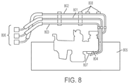
- FIG. 8 is a hydraulic system assembled/mounted on a gas turbine engine of an aircraft including the hydraulic lines.
- FIG. 9 shows how a single integrated conduit can replace a portion of the hydraulic lines in the hydraulic system shown in FIG. 8 .
- FIG. 3 Shown in FIG. 3 is an integrated fluid conduit according to one aspect of the invention.
- the integrated fluid conduit 300 of FIG. 3 is optimized for fuel delivery in a gas turbine engine of a jet airplane.
- the conduit includes a pilot secondary line 301 , a pilot primary line 302 , and a main fuel line 303 .
- the cross section of FIG. 3 strategically places high-pressure fluid in a circular flow-profile 303 to minimize hoop stress, addressing proof capability issue, and places relatively-low-pressure channels in remaining non-circular flow-profiles 301 , 302 , balancing pressure forces in the integrated duct 300 .
- each section of duct includes seven bends 401 , 402 , 403 , 404 , 405 , 406 , and 407 that lower bending stiffness and improve flexibility of the duct.
- the bends in the fluid conduit have a radius of curvature ranging from less than twice the diameter of the fluid conduit to softer bends on the order of less than five times the diameter of the fluid conduit.
- a circular outer duct profile was retained as it would allow for adding standard structural damping features, such as clamps, later on in the design cycle, if deemed necessary, to lower vibration response and achieve required high-cycle fatigue life.
- a non-circular outer duct profile discussed below with reference to FIG. 7 , may be used in a specific lower engine vibration environment or where alternate damping methods/devices are available for use.
- the integral duct 400 of FIG. 4 is utilized in the design of a fuel delivery manifold system 500 where fuel is delivered directly from the integral duct 502 to fuel nozzles 501 .
- the proposed cross-section 300 of FIG. 3 addressed pressure drop requirement and proof capability for the fuel manifold concept.
- FIG. 6 shows a close-up of the fuel manifold system shown in FIG. 5 .
- the arrangement of ducts 601 , 602 in the fuel manifold system 600 is staggered about the fuel nozzles 603 , 604 .
- a non-circular outer duct profile as shown in FIG. 7 that is capable of lowering the duct weight.
- the non-circular integrated duct shown in FIG. 7 provides a rigid conduit with an external surface that is continuous around the periphery of the conduit.
- the outer circumference of the duct 700 is continuous so that the individual lines 701 , 702 , and 703 within the duct 700 are integrated with each other.
- This duct design provides a rigid series of ducts in a lower weight arrangement suitable for a specific lower engine vibration environment or where alternate damping methods/devices are available for use.
- the integrated fluid conduit of the present invention may be utilized as the fluid conduit in a gas turbine/jet engine hydraulic system as shown in FIG. 9 .
- an engine driven pump 807 is mounted on the auxiliary gear box 804 on the engine case 805 .
- the suction/return line 801 , case drain line 802 , and pressure/supply line 803 are routed from the engine driven pump 807 to the aircraft interface or pylon attachment 806 .
- a combination of flexible hoses and rigid lines is utilized for each hydraulic line, trading off between ease of assembly offered by a hose and its higher weight and cost.
- the integrated fluid conduit according to this embodiment of the present invention replaces the rigid section of the three hydraulic lines—pressure/supply line 803 , suction/return line 801 and case drain line 802 —with a single integrated fluid conduit. As shown in FIG.
- the formerly separate rigid/metallic lines 801 , 802 and 803 are consolidated into an integrated line 909 , which includes three interior conduits 901 , 902 , and 903 .
- the design of the integrated conduit 909 may have a circular outer perimeter as shown in FIG. 3 discussed above.
- the integrated conduit may have a non-circular outer perimeter as shown in FIG. 7 .
- the integrated conduit shown in FIG. 9 simplifies the packaging and the need for support brackets 808 shown in FIG. 8 , and significantly lowers part count.
- This design may include several bends in the conduit path to allow a feasible routing from the engine driven hydraulic pump 907 to the pylon 906 .
- the design may include several connected pieces of integrated duct between the hydraulic pump 907 and pylon 906 because of manufacturing constraints. For example, current additive manufacturing stations/tables have limited space in which to build lengthy conduits. Interconnecting hardware may be required for a continuous fluid channel embodiment.
- the additive manufacturing methods discussed above offer flexibility in forming/molding the inlets and outlets of each distinct fluid channel/passage of an integrated conduit to desired shape. This desired shape allows attachment/interface with standard or non-standard fluid fittings/end-pieces.
- the integrated fluid conduit may have substantially circular ends for standard interface hardware such as fluid fittings/joints or it may have inlet/outlet taps in the run/route of the conduit for interface hardware on each channel/passage, as shown
- the entire hydraulic fluid conduit in the above system may be formed from a single integrated conduit, or from individual sections.
- the portions of the hydraulic system requiring significant curvature of the conduit may preferably be manufactured according to the present invention.
- the hydraulic system may have at least two fluid passages within the fluid conduit, but may alternatively have several fluid passages depending on design requirements. Further, portions of the hydraulic system may be made from an integrated conduit having one specified geometry, while other portions of the hydraulic system are made from integrated conduit having a different cross sectional geometry.
- the integrated conduits of the present invention may be manufactured according to an additive printing technique, including selective laser sintering (SLS), direct metal laser sintering (DMLS) and three dimensional printing (3DP).
- SLS selective laser sintering
- DMLS direct metal laser sintering
- 3DP three dimensional printing
- the materials can include stainless steel, aluminum, titanium, Inconel 625, Inconel 718, cobalt chrome, among other metal materials.
- powdered material is melted or sintered to form each part layer.
- the SLS process utilizes powdered plastic materials that are selectively sintered by a laser layer-by-layer.
- Other types of additive manufacturing techniques include 3D printing including stereolithography (SLA), jetted photopolymer, or ink jet printing.
- additive printing include solid-based processes, which use non-powdered materials that are layered one on top of another and subsequently cut out. These methods includes laminated object manufacturing (LOM) or fused deposition modeling (FDM). Any of the above techniques may be utilized to form the integrated conduit having the required curvature for a particular application. Exemplary embodiments of a fluid conduit and method for manufacturing the same are described above in detail. The methods and systems are not limited to the specific embodiments described herein, but rather components of the methods and systems may be utilized independently and separately from other components described herein. For example, the methods and systems described herein may have other industrial and/or consumer application and are not limited to practice with only gas turbine engines as described herein. Rather, the present invention can be implemented and utilized in connection with many other industries.
- LOM laminated object manufacturing
- FDM fused deposition modeling
Landscapes
- Engineering & Computer Science (AREA)
- General Engineering & Computer Science (AREA)
- Chemical & Material Sciences (AREA)
- Mechanical Engineering (AREA)
- Combustion & Propulsion (AREA)
- Analytical Chemistry (AREA)
- Physics & Mathematics (AREA)
- Fluid Mechanics (AREA)
- Rigid Pipes And Flexible Pipes (AREA)
Abstract
Description
Claims (20)
Applications Claiming Priority (3)
| Application Number | Priority Date | Filing Date | Title |
|---|---|---|---|
| IN201641022394 | 2016-06-30 | ||
| IN201641022394 | 2016-06-30 | ||
| PCT/US2017/037591 WO2018005106A1 (en) | 2016-06-30 | 2017-06-15 | Integral fluid conduit |
Publications (2)
| Publication Number | Publication Date |
|---|---|
| US20200309287A1 US20200309287A1 (en) | 2020-10-01 |
| US11262003B2 true US11262003B2 (en) | 2022-03-01 |
Family
ID=59227925
Family Applications (1)
| Application Number | Title | Priority Date | Filing Date |
|---|---|---|---|
| US16/310,838 Active 2037-11-18 US11262003B2 (en) | 2016-06-30 | 2017-06-15 | Integral fluid conduit |
Country Status (4)
| Country | Link |
|---|---|
| US (1) | US11262003B2 (en) |
| EP (1) | EP3478951B1 (en) |
| CN (1) | CN109415980B (en) |
| WO (1) | WO2018005106A1 (en) |
Families Citing this family (7)
| Publication number | Priority date | Publication date | Assignee | Title |
|---|---|---|---|---|
| US10454444B2 (en) | 2016-04-25 | 2019-10-22 | Kumu Networks, Inc. | Integrated delay modules |
| EP3563962B1 (en) * | 2018-05-01 | 2021-12-08 | Hamilton Sundstrand Corporation | Duct manufacturing method |
| US20200189494A1 (en) * | 2018-12-13 | 2020-06-18 | Safran Landing Systems Canada Inc. | Landing gear structure with harness |
| US12044409B2 (en) | 2019-09-20 | 2024-07-23 | Rtx Corporation | Casing integrated fluid distribution system |
| US11369985B2 (en) | 2019-10-04 | 2022-06-28 | Delavan Inc | Fluid conduits with heat shielding |
| FR3130322B1 (en) * | 2021-12-09 | 2024-11-22 | Safran Aircraft Engines | Fuel distribution assembly for turbomachine |
| CN114151827B (en) * | 2022-02-08 | 2022-07-08 | 中国航发四川燃气涡轮研究院 | Flexible fuel manifold integrated with fuel nozzle |
Citations (10)
| Publication number | Priority date | Publication date | Assignee | Title |
|---|---|---|---|---|
| CN1139735A (en) | 1995-07-03 | 1997-01-08 | Abb管理有限公司 | Fuel inlet pipe for gas turbine with circular combustion chamber |
| US20090255602A1 (en) * | 2008-04-11 | 2009-10-15 | General Electric Company | Unitary conduit for transporting fluids |
| WO2009148680A2 (en) | 2008-04-11 | 2009-12-10 | General Electric Company | Unitary conduit for transporting fluids and method of manufacturing |
| US20100051726A1 (en) | 2008-08-28 | 2010-03-04 | Woodward Governor Company | Multi Passage Fuel Manifold and Methods of Construction |
| CN103062800A (en) | 2011-10-24 | 2013-04-24 | 通用电气公司 | System for turbine combustor fuel mixing |
| US20140096857A1 (en) * | 2011-06-17 | 2014-04-10 | Sampo Humalainen | Pipe assembly for district heating network |
| CN104379879A (en) | 2012-06-15 | 2015-02-25 | 通用电气公司 | Fluid conduit |
| CN204691907U (en) | 2015-04-14 | 2015-10-07 | 浙江海洋学院 | A kind of aviation fuel pipe |
| EP2942510A1 (en) | 2014-05-09 | 2015-11-11 | Ott, Joe | Fluid couplings and methods for additive manufacturing thereof |
| EP2942489A1 (en) | 2014-05-09 | 2015-11-11 | Ott, Joe | Shrouded conduit for arranging in a fluid flowpath and corresponding method of manufacturing |
-
2017
- 2017-06-15 WO PCT/US2017/037591 patent/WO2018005106A1/en not_active Ceased
- 2017-06-15 EP EP17733686.4A patent/EP3478951B1/en active Active
- 2017-06-15 CN CN201780040168.7A patent/CN109415980B/en active Active
- 2017-06-15 US US16/310,838 patent/US11262003B2/en active Active
Patent Citations (12)
| Publication number | Priority date | Publication date | Assignee | Title |
|---|---|---|---|---|
| CN1139735A (en) | 1995-07-03 | 1997-01-08 | Abb管理有限公司 | Fuel inlet pipe for gas turbine with circular combustion chamber |
| US20090255602A1 (en) * | 2008-04-11 | 2009-10-15 | General Electric Company | Unitary conduit for transporting fluids |
| WO2009148680A2 (en) | 2008-04-11 | 2009-12-10 | General Electric Company | Unitary conduit for transporting fluids and method of manufacturing |
| US20100051726A1 (en) | 2008-08-28 | 2010-03-04 | Woodward Governor Company | Multi Passage Fuel Manifold and Methods of Construction |
| US20140096857A1 (en) * | 2011-06-17 | 2014-04-10 | Sampo Humalainen | Pipe assembly for district heating network |
| CN103062800A (en) | 2011-10-24 | 2013-04-24 | 通用电气公司 | System for turbine combustor fuel mixing |
| CN104379879A (en) | 2012-06-15 | 2015-02-25 | 通用电气公司 | Fluid conduit |
| EP2942510A1 (en) | 2014-05-09 | 2015-11-11 | Ott, Joe | Fluid couplings and methods for additive manufacturing thereof |
| EP2942489A1 (en) | 2014-05-09 | 2015-11-11 | Ott, Joe | Shrouded conduit for arranging in a fluid flowpath and corresponding method of manufacturing |
| US20150323107A1 (en) | 2014-05-09 | 2015-11-12 | United Technologies Corporation | Fluid couplings and methods for additive manufacturing thereof |
| US20150322820A1 (en) * | 2014-05-09 | 2015-11-12 | United Technologies Corporation | Shrouded conduit for arranging a fluid flowpath |
| CN204691907U (en) | 2015-04-14 | 2015-10-07 | 浙江海洋学院 | A kind of aviation fuel pipe |
Non-Patent Citations (6)
| Title |
|---|
| English Translation of Chinese office action for application 201780040168.7 dated Jun. 9, 2020 (14 pages). |
| Examination Report Priority Search Results for application IN 201641022394 dated Nov. 7, 2019 (7 pages). |
| International Preliminary Report on Patentability for application PCT/US2017/037591 dated Jan. 1, 2019 (5 pages). |
| International Search Report and Written Opinion dated Sep. 19, 2017 which was issued in connection with PCT application No. PCT/US17/37591 which was filed on Jun. 15, 2017. |
| U.S. Appl. No. 14/407,400, filed Jun. 14, 2013 by General Electric Company. |
| U.S. Appl. No. 14/685,631, filed Apr. 14, 2015 by General Electric Company. |
Also Published As
| Publication number | Publication date |
|---|---|
| EP3478951B1 (en) | 2022-10-05 |
| WO2018005106A1 (en) | 2018-01-04 |
| CN109415980A (en) | 2019-03-01 |
| CN109415980B (en) | 2021-10-22 |
| EP3478951A1 (en) | 2019-05-08 |
| US20200309287A1 (en) | 2020-10-01 |
Similar Documents
| Publication | Publication Date | Title |
|---|---|---|
| US11262003B2 (en) | Integral fluid conduit | |
| EP3081783B1 (en) | Thermally-coupled fuel manifold | |
| US11898492B2 (en) | Fluid exchange apparatuses and methods of exchanging fluids between streams | |
| US11168942B2 (en) | Circular core for heat exchangers | |
| EP4230943B1 (en) | Integrated horn structures for heat exchanger headers | |
| EP3109548B1 (en) | Combustion system with combustor dome integrated fuel manifold | |
| US20190024988A1 (en) | Header assembly for a heat exchanger | |
| US12013196B2 (en) | Integrated cooling sub-system | |
| CN110684993A (en) | Duct assembly and method of forming | |
| US20200017199A1 (en) | Active flow control systems for aircraft and related methods | |
| EP3822079A1 (en) | Self-supporting additively-manufactured heat exchanger header | |
| US20220299201A1 (en) | Spray heads for use with desuperheaters and desuperheaters including such spray heads | |
| EP3839315B1 (en) | Gimbals and their manufacture | |
| CN109707469B (en) | Adjustable flexible attachment structure, method of providing compliance therewith, and method of forming same | |
| US11377976B2 (en) | Surface cooler and method of forming | |
| US12618499B2 (en) | Gimbals and their manufacture |
Legal Events
| Date | Code | Title | Description |
|---|---|---|---|
| AS | Assignment |
Owner name: GENERAL ELECTRIC COMPANY, NEW YORK Free format text: ASSIGNMENT OF ASSIGNORS INTEREST;ASSIGNORS:GROVER, VARUN;WOLFE, JARED MATTHEW;SIGNING DATES FROM 20151120 TO 20151130;REEL/FRAME:047801/0566 |
|
| FEPP | Fee payment procedure |
Free format text: ENTITY STATUS SET TO UNDISCOUNTED (ORIGINAL EVENT CODE: BIG.); ENTITY STATUS OF PATENT OWNER: LARGE ENTITY |
|
| STPP | Information on status: patent application and granting procedure in general |
Free format text: RESPONSE TO NON-FINAL OFFICE ACTION ENTERED AND FORWARDED TO EXAMINER |
|
| STPP | Information on status: patent application and granting procedure in general |
Free format text: FINAL REJECTION MAILED |
|
| STPP | Information on status: patent application and granting procedure in general |
Free format text: DOCKETED NEW CASE - READY FOR EXAMINATION |
|
| STPP | Information on status: patent application and granting procedure in general |
Free format text: NON FINAL ACTION MAILED |
|
| STPP | Information on status: patent application and granting procedure in general |
Free format text: RESPONSE TO NON-FINAL OFFICE ACTION ENTERED AND FORWARDED TO EXAMINER |
|
| STPP | Information on status: patent application and granting procedure in general |
Free format text: NOTICE OF ALLOWANCE MAILED -- APPLICATION RECEIVED IN OFFICE OF PUBLICATIONS |
|
| STCF | Information on status: patent grant |
Free format text: PATENTED CASE |
|
| MAFP | Maintenance fee payment |
Free format text: PAYMENT OF MAINTENANCE FEE, 4TH YEAR, LARGE ENTITY (ORIGINAL EVENT CODE: M1551); ENTITY STATUS OF PATENT OWNER: LARGE ENTITY Year of fee payment: 4 |