US11259393B2 - Electric neutralizer, electronic scale equipped with electric neutralizer, and neutralization method - Google Patents
Electric neutralizer, electronic scale equipped with electric neutralizer, and neutralization method Download PDFInfo
- Publication number
- US11259393B2 US11259393B2 US16/977,794 US201816977794A US11259393B2 US 11259393 B2 US11259393 B2 US 11259393B2 US 201816977794 A US201816977794 A US 201816977794A US 11259393 B2 US11259393 B2 US 11259393B2
- Authority
- US
- United States
- Prior art keywords
- static
- static eliminating
- eliminating
- mode
- speed
- Prior art date
- Legal status (The legal status is an assumption and is not a legal conclusion. Google has not performed a legal analysis and makes no representation as to the accuracy of the status listed.)
- Active
Links
Images


Classifications
-
- H—ELECTRICITY
- H01—ELECTRIC ELEMENTS
- H01T—SPARK GAPS; OVERVOLTAGE ARRESTERS USING SPARK GAPS; SPARKING PLUGS; CORONA DEVICES; GENERATING IONS TO BE INTRODUCED INTO NON-ENCLOSED GASES
- H01T19/00—Devices providing for corona discharge
- H01T19/04—Devices providing for corona discharge having pointed electrodes
-
- H—ELECTRICITY
- H01—ELECTRIC ELEMENTS
- H01T—SPARK GAPS; OVERVOLTAGE ARRESTERS USING SPARK GAPS; SPARKING PLUGS; CORONA DEVICES; GENERATING IONS TO BE INTRODUCED INTO NON-ENCLOSED GASES
- H01T23/00—Apparatus for generating ions to be introduced into non-enclosed gases, e.g. into the atmosphere
-
- H—ELECTRICITY
- H05—ELECTRIC TECHNIQUES NOT OTHERWISE PROVIDED FOR
- H05F—STATIC ELECTRICITY; NATURALLY-OCCURRING ELECTRICITY
- H05F3/00—Carrying-off electrostatic charges
- H05F3/04—Carrying-off electrostatic charges by means of spark gaps or other discharge devices
-
- H—ELECTRICITY
- H05—ELECTRIC TECHNIQUES NOT OTHERWISE PROVIDED FOR
- H05F—STATIC ELECTRICITY; NATURALLY-OCCURRING ELECTRICITY
- H05F3/00—Carrying-off electrostatic charges
- H05F3/06—Carrying-off electrostatic charges by means of ionising radiation
Definitions
- the present invention relates to a static eliminator that quickly eliminates static from a specimen while having a good ion balance, an electronic balance including the static eliminator, and a static eliminating method of the static eliminator.
- An electronic balance to be used for precision analysis, etc. has an extremely high weighing sensitivity, and even static electricity of a specimen becomes a factor in causing a weighing error.
- an electronic balance with a windshield including a static eliminator (ionizer) that neutralizes the electrical charge (hereinafter, referred to as “eliminating static”) of a specimen by generating ions has been proposed (Patent Literature 1).
- both of positive ions and negative ions can be emitted by one static eliminating needle, whereas the distance of static elimination is short and a fan or the like is required, and the amount of ions is small, so that static elimination takes time.
- the DC method at least two static eliminating needles are required, however, the amount of ions that are emitted is larger than that of the AC method, and ions can scatter far without wind, and the static eliminating time is short (refer to FIGS. 12 and 13 ).
- a pulsed DC method is available. This is a method in which short-time plus-like DC voltage application/interruption are alternately repeated to a total of two static eliminating needles consisting of a positive electrode and a negative electrode to cause these static eliminating needles to emit negative ions and positive ions alternately (refer to FIG. 14 ). Ions can be scattered far as in the DC method, and in addition, the alternate emission of positive ions and negative ions prevents ions from being bonded to each other, so that the amount of ions to be used for static elimination is large, and the static eliminating time can be further shortened than that by the DC method.
- the pulsed DC method has a problem in which ion balances of a specimen and the area around the specimen deteriorate under the influence of either positive or negative ions emitted last.
- the present invention was made in view of this problem, and an object of the present invention is to provide a static eliminator that quickly eliminates static from a specimen while having a good ion balance, an electronic balance including the static eliminator, and a static eliminating method of the static eliminator.
- a static eliminator of the present disclosure is a static eliminator configured to eliminate static from a static eliminating object by ions generated by applying a high voltage to a static eliminating needle, and has a high-speed static eliminating mode configured to eliminate static from the static eliminating object at a high speed, and a relaxation static eliminating mode to be executed by a voltage application method different from that of the high-speed static eliminating mode and configured to regulate ion balances of the static eliminating object and the area around the static eliminating object.
- the high-speed static eliminating mode is executed by voltage application to the static eliminating needle by a pulsed DC method
- the relaxation static eliminating mode is executed by voltage application to the static eliminating needle by a DC method.
- a pulse period in the pulsed DC method is determined according to a distance from the static eliminating needle to the static eliminating object.
- a table of optimum periods with respect to each distance from the static eliminating needle to the static eliminating object, or a function of an optimum period with respect to the distance from the static eliminating needle to the static eliminating object is stored in advance, and as the pulse period in the pulsed DC method, an optimum period obtained from the table or the function is used.
- the relaxation static eliminating mode is executed following execution of the high-speed static eliminating mode.
- an electronic balance including a static eliminator which includes a placing pan on which a specimen can be placed, a windshield configured to cover the placing pan and define a weighing chamber, and the static eliminator disposed inside the weighing chamber, wherein voltage application in the high-speed static eliminating mode is performed by a pulsed DC method using a period determined according to a distance corresponding to a distance from a center position of the placing pan to the static eliminator.
- a static eliminating method uses a static eliminator configured to eliminate static from a static eliminating object by ions generated by applying a high voltage to a static eliminating needle, and includes a high-speed static eliminating step of eliminating static from the static eliminating object at a high speed, and a relaxation static eliminating step of regulating ion balances of the static eliminating object and the area around the static eliminating object, which is performed by a voltage application method different from that of the high-speed static eliminating mode.
- a static eliminator that quickly eliminates static from a specimen while having a good ion balance, an electronic balance including the static eliminator, and a static eliminating method of the static eliminator can be provided.
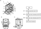
- FIG. 1(A) is a perspective view of an electronic balance including a static eliminator according to an embodiment of the present invention
- FIG. 1(B) is a front view
- FIG. 1(C) is a right side view.
- FIG. 2 is a block diagram of the same electronic balance.
- FIGS. 3(A) and 3(B) are graphs illustrating voltages and ion outputs of static eliminating needles, in which FIG. 3(A) is a positive electrode, and FIG. 3(B) is a negative electrode.
- FIG. 4 is a flowchart of static elimination.
- FIG. 5 is a graph illustrating relationships between a pulse period T and a decay time Ts with respect to each distance L from the static eliminating needles to a specimen.
- FIGS. 6(A) and 6(B) are schematic views illustrating test conditions in FIG. 5 , in which FIG. 6(A) is a plan view, and FIG. 6(B) is a right side view.
- FIGS. 7(A), 7(B) , and 7 (C) are graphs illustrating charged voltage changes of a specimen (acrylic board) in respective modes, in which FIG. 7(A) illustrates a case where only a high-speed static eliminating mode M 1 was executed, FIG. 7(B) illustrates a case where only a relaxation static eliminating mode M 2 was executed, and FIG. 7(C) illustrates a case where both of the high-speed static eliminating mode M 1 and the relaxation static eliminating mode M 2 were executed.
- FIGS. 8(A), 8(B) , and 8 (C) are graphs illustrating charged voltage changes of a windshield in respective modes, in which FIG. 8(A) illustrates a case where only the high-speed static eliminating mode M 1 was executed, FIG. 8(B) illustrates a case where only the relaxation static eliminating mode M 2 was executed, and FIG. 8(C) illustrates a case where both of the high-speed static eliminating mode M 1 and the relaxation static eliminating mode M 2 were executed.
- FIGS. 9(A) and 9(B) are schematic views illustrating test conditions in FIG. 8 , and depict an electronic balance, in which FIG. 9(A) is a plan view, and FIG. 9(B) is a front view.
- FIG. 10 is a perspective view of a static eliminator according to another embodiment of the present invention.
- FIGS. 11(A) and (B) depict a modification of the present invention, and are graphs illustrating voltages and ion outputs of static eliminating needles, in which FIG. 11(A) is a positive electrode, and FIG. 11(B) is a negative electrode.
- FIG. 12 is a graph illustrating a voltage and an ion output by the AC method.
- FIGS. 13(A) and (B) are graphs illustrating voltages and ion outputs by the DC method, in which FIG. 13(A) is a positive electrode, and FIG. 13(B) is a negative electrode.
- FIGS. 14(A) and (B) are graphs illustrating voltages and ion outputs in a pulsed DC method, in which FIG. 14(A) is a positive electrode, and FIG. 14(B) is a negative electrode.
- FIG. 1 depict an electronic balance 1 including a static eliminator according to the present embodiment
- FIG. 2 is a block diagram of the electronic balance 1 .
- the electronic balance 1 includes a balance main body 10 , a windshield 4 disposed at an upper portion of the balance main body 10 and mounted on the balance main body 10 , and a static eliminator 6 disposed inside the windshield 4 .
- the balance main body 10 has, on an upper surface thereof, a weighing pan 2 on which a specimen is placed, and inside the balance main body 10 , a load detecting unit 26 that detects a load placed on the weighing pan 2 , an A/D converter 28 that converts a detected analog signal to a digital signal, and a balance control unit 30 , are housed.
- the balance control unit 30 is a microcontroller configured by mounting a CPU, a memory, etc., on an integrated circuit, and controls the balance main body 10 and the static eliminator 6 based on a program stored in the memory.
- a display unit 22 of a display that displays weighing results and a status, etc., and an input unit 24 as switches to input commands are provided on a front upper surface of the balance main body 10 .
- the windshield 4 defines a weighing chamber 12 inside which the weighing pan 2 is disposed.
- Each of left, right, and upper walls of the weighing chamber 12 has a door 14 as an entrance and exit of the weighing chamber 12 , and on a rear wall of the weighing chamber 12 , the static eliminator 6 is disposed.
- the left, right, and upper walls (including the doors 14 ) and a front wall of the weighing chamber 12 are made of a transparent resin or glass so as to facilitate observation of the internal state.
- the static eliminator 6 generates high voltages by high-voltage generating circuits (a positive electrode 18 A and a negative electrode 18 B) provided inside, and by applying these high voltages to static eliminating needles (a positive electrode 8 A and a negative electrode 8 B), causes corona discharge so as to emit positive ions from the static eliminating needle 8 A of the positive electrode and negative ions from the static eliminating needle 8 B of the negative electrode toward the front side, respectively.
- This high-voltage application is performed by the DC method, and needs two or more static eliminating needles 8 , however, as compared with the AC method that is also a voltage application method, the amount of ions to be lost due to ionic bond is smaller, so that the amount of ions that can be used for static elimination is larger, and the amount of charge can be significantly reduced in a short time with respect to a specimen to be static eliminated. In addition, as compared with the AC method, ions can be scattered far, so that an ion blowing fan is unnecessary. No air flow is generated, so that the effect on weighing is small.
- the two static eliminating needles ( 8 A and 8 B) are juxtaposed on the left and right while being spaced from each other.
- a proximity sensor 16 is an electronic device that can switch between ON/OFF by simply approaching the sensor without touching it.
- the static eliminator 6 has the proximity sensor 16 on a main body surface, and a signal is transmitted to start static elimination by the user simply bringing his or her hand or a specimen close to the proximity sensor 16 .
- the proximity sensor 16 may be provided on the balance main body 10 .
- a foot switch or the like that enables a user to perform turning ON/OFF with his/her foot may be provided separately so that the user can use his/her hands.
- the static eliminator 6 Control of the static eliminator 6 is performed by a built-in static eliminator control unit 20 .
- the static eliminator control unit 20 is also a microcontroller configured by mounting a CPU, a memory, etc., on an integrated circuit, and controls voltage application to the respective static eliminating needles ( 8 A and 8 B) by controlling the high-voltage generating circuits ( 18 A and 18 B) in each mode described later.
- the static eliminator 6 itself is controlled by the balance control unit 30 .
- FIG. 3 are graphs illustrating voltages and ion outputs of the static eliminating needles, in which FIG. 3(A) illustrates the positive electrode, and FIG. 3(B) illustrates the negative electrode, the horizontal axis represents time, and the vertical axis represents voltage. Ions are not generated unless the voltage becomes high to some extent, so that ions are output (emitted) only in the hatched regions.
- FIG. 4 is a flowchart of static elimination.
- the proximity sensor 16 reacts (S 1 ) as a trigger, and the static eliminator 6 first executes a high-speed static eliminating mode M 1 (S 2 ) to eliminate static from the specimen at a high speed, and then, executes a relaxation static eliminating mode M 2 (S 3 ). After the relaxation static eliminating mode M 2 is executed, the static elimination ends.
- the pulsed DC method is an application method in which short-time pulse-like voltage application/interruption are periodically repeated.
- One period (period T) of application/interruption is the same between the electrodes, and inverting voltage application is repeated in which voltages that have the same period T but are shifted by a half period from each other are alternately applied to the static eliminating needle 8 A of the positive electrode and the static eliminating needle 8 B of the negative electrode.
- an optimum period To is selected, and the high-speed static eliminating mode M 1 is executed with the optimum period To.
- the pulsed DC method is excellent in decay time characteristics. While voltage of an electrically charged static eliminating object is gradually decreased by static elimination, the decay time characteristics mean a time to be taken until the voltage reaches an allowable voltage level, where the allowable voltage level is a voltage at which a weighing error does not become a problem. Therefore, the decay time characteristics can be said to be excellent when the voltage of a charged static eliminating object can be decreased to the allowable voltage level in a short time.
- the decay time characteristics relate to the distance L from the static eliminator to the static eliminating object and the pulse period T, and therefore, by selecting an optimum period To with respect to the distance L as the period T, the decay time characteristics can be further improved.
- FIG. 5 is a graph of test data of the pulse period T and the decay time Ts when an acrylic board 32 was electrically charged as a test specimen and the high-speed static eliminating mode M 1 was executed by the static eliminator 6 .
- FIG. 6 are schematic views illustrating conditions of the test, in which FIG. 6(A) is a plan view, and FIG. 6(B) is a right side view. A time (decay time Ts) taken until the charged voltage of the acrylic board 32 reaches an allowable voltage level (here, set to 1/10 of the original charged voltage) was measured while changing the pulse period T with respect to each distance L.
- an allowable voltage level here, set to 1/10 of the original charged voltage
- the optimum period To at which the decay time Ts becomes the shortest differs by distance L.
- a pulse period T that realizes excellent decay time characteristics tends to become shorter as the distance L becomes shorter.
- a table of optimum periods To with respect to distances L or a function of the optimum period To with respect to the distance L, derived based on the test results, are stored in advance in the static eliminator control unit 20 .
- the static eliminator 6 is attached to the rear wall of the inside of the windshield 4 , so that the distance L from the static eliminator 6 to the static eliminating object (a distance corresponding to a distance from a center position of the weighing pan 2 to the static eliminator 6 ) is almost constant, so that the optimum period To can be set in advance.
- a configuration is also preferable in which a distance sensor is added, a distance to a specimen is measured simultaneously with the start of static elimination, and based on the results of the measurement, an optimum period To is determined each time, and the high-speed static eliminating mode M 1 is executed.
- a configuration is also preferable which enables a user to select or input a distance L with the input unit 24 .
- the pulsed DC method has an advantage in that the excellent decay time characteristics enable high-speed static elimination, however, positive ions and negative ions are alternately output, so that ions on the polarity side output last remain in the specimen and in the area around the specimen and tend to deteriorate the ion balance.
- the static eliminator 6 is installed inside the weighing chamber 12
- the area around the static eliminator 6 is enclosed by walls, so that positive ions easily accumulate on an inner wall of the weighing chamber 12 closer to the static eliminating needle 8 A of the positive electrode, and negative ions easily accumulate on an inner wall closer to the static eliminating needle 8 B of the negative electrode. Accumulation of a large amount of ions (electric charge) may cause, for example, powder to be blown off when the powder is brought close.
- the relaxation static eliminating mode M 2 is executed.
- the relaxation static eliminating mode M 2 voltage application is performed by the DC method in which voltages are simultaneously applied to both of the static eliminating needle 8 A of the positive electrode and the static eliminating needle 8 B of the negative electrode.
- Positive ions and negative ions are simultaneously emitted in the entire weighing chamber 12 and relax electric charge in the specimen and the area around the specimen in a well-balanced manner, and the ion balance in the weighing chamber 12 including both side inner walls of the weighing chamber 12 is improved.
- the relaxation static eliminating mode M 2 and the high-speed static eliminating mode M 1 are assumed to have the same execution times, however, the execution time of the relaxation static eliminating mode M 2 may be shorter than that of the high-speed static eliminating mode M 1 . It has been experimentally confirmed that the relaxation static eliminating mode M 2 functions sufficiently even in a short time.
- the static eliminating time is selected from among 1 second, 3 seconds, and 10 seconds or a desired static eliminating time is manually input with the input unit 24 .
- the execution time of the relaxation static eliminating mode M 2 is fixed to 0.4 seconds, and a time obtained by subtracting the execution time of the relaxation static eliminating mode M 2 from the input static eliminating time is the execution time of the high-speed static eliminating mode M 1 . It is also possible that a time ratio of the relaxation static eliminating mode M 2 and the high-speed static eliminating mode M 1 is stored in advance, and the static eliminating time is divided between the modes.
- the high-speed static eliminating mode M 1 in which voltage application is performed by the pulsed DC method, the charge in a specimen is quickly relaxed.
- the specimen has already been static eliminated to the allowable voltage level by the high-speed static eliminating mode M 1 , the ion balance deteriorated by the ions on the polarity side emitted last is also relaxed by the relaxation static eliminating mode M 2 .
- the total static eliminating time for both modes is shorter than that in the DC method or in the AC method, and residual charge caused by the pulsed DC method is also relaxed by the relaxation static eliminating mode M 2 , so that the charge eliminating performance is high in total.
- the high-speed static eliminating mode M 1 and the relaxation static eliminating mode M 2 use different voltage application methods, and static elimination can be performed by utilizing the advantages of the respective voltage application methods.
- an optimum period To corresponding to the distance L from the static eliminator to the static eliminating object is selected, so that the specimen can be static eliminated at a higher speed.
- the relaxation static eliminating mode M 2 is executed following the high-speed static eliminating mode M 1 , so that loss of the ion balance in the weighing chamber 12 is immediately relaxed. Therefore, since the ion balance is not left in an unbalanced state, adverse effects of static elimination on weighing can be minimized.
- the static eliminator 6 is installed inside and integrated with the windshield 4 , and static elimination can be performed in the weighing chamber 12 , and this is highly convenient.
- the distance L from the static eliminator 6 to the weighing pan 2 is almost constant, so that the optimum period To is selected from the beginning, and a specimen is subjected to high-speed static elimination by only placing the specimen into the weighing chamber 12 for weighing, so that the work efficiency is high.
- FIG. 7 are graphs of the results of the experiment performed to demonstrate the effect of the present embodiment, and charged voltage changes of the acrylic board 32 when the acrylic board 32 was electrically charged and static eliminated in the respective modes under the same test conditions as in FIG. 6 were measured.
- FIG. 7(A) illustrates results obtained when only the high-speed static eliminating mode M 1 was executed
- FIG. 7(B) illustrates results obtained when only the relaxation static eliminating mode M 2 was executed
- FIG. 7(C) illustrates results obtained when the relaxation static eliminating mode M 2 was executed after the high-speed static eliminating mode M 1 was executed.
- the charged voltage linearly decreased from just after the start of static elimination, and the time (decay time) until reaching the allowable voltage level was shorter than in the case where only the relaxation static eliminating mode M 2 was executed, so that excellent decay time characteristics were obtained.
- the voltage is applied by the pulsed DC method, so that negative ions and positive ions are alternately emitted, and the charged voltage fluctuates up and down around 0 and is unstable although it is within the allowable voltage level range, and the ion balance is poor. Therefore, by executing the relaxation static eliminating mode M 2 after the high-speed static eliminating mode M 1 (refer to FIG. 7(C) ), the charged voltage can be stabilized at almost 0.
- the static eliminating time was set to 3 seconds by way of example, however, the static eliminating time can be made shorter, and even in this case, the effect can be sufficiently obtained. Even when the charge amount is large, static can be quickly eliminated to have a good ion balance.
- FIG. 8 are graphs illustrating results of another experiment conducted to further demonstrate the effect, for which charged voltages of the windshield 4 when the respective modes were executed were measured.
- FIG. 8(A) illustrates results obtained when only the high-speed static eliminating mode M 1 was executed
- FIG. 8(B) illustrates results obtained when only the relaxation static eliminating mode M 2 was executed
- FIG. 8(C) illustrates results obtained when the relaxation static eliminating mode M 2 was executed after the high-speed static eliminating mode M 1 was executed.
- FIG. 9 are schematic views illustrating conditions of the test, and depict the electronic balance 1 , in which FIG. 9(A) is a plan view, and FIG. 9(B) is a front view, and the arrows P in the drawings indicate charged voltage measurement positions on the windshield 4 .
- the charged voltage measurement position P on the windshield 4 is on a left side inner wall close to the static eliminating needle 8 A of the positive electrode, and positive ions comparatively easily accumulate there, so that the charged voltages of the windshield 4 illustrated in FIG. 8 all changed to the positive side except the times just after the start of ion output.
- the relaxation static eliminating mode is executed after the high-speed static eliminating mode M 1 , as illustrated in FIG. 8(C) , the charged voltage repeatedly increases and decreases, however, it was confirmed that by executing the relaxation static eliminating mode M 2 , the charged voltage after the ion output decreased to a level equivalent to that in the case of only the relaxation static eliminating mode M 2 .
- the relaxation static eliminating mode M 2 can improve not only the ion balance of the static eliminating object but also the ion balance in the area around (windshield 4 ) the static eliminating object.
- FIG. 10 is a perspective view of a static eliminator 6 ′ as another embodiment of the present invention.
- the static eliminator 6 ′ has the same configuration as that of the static eliminator 6 of the embodiment described above except that the static eliminator 6 ′ is self-supporting by using a stand 34 equipped on its back surface, and can operate alone.
- the static eliminator 6 ′ is configured to obtain electric power from an external power supply by a detachable cord.
- the proximity sensor 16 When a specimen is brought close to the front of the static eliminator 6 ′, the proximity sensor 16 operates as a trigger, and by application of high voltages generated by the high-voltage generating circuits ( 18 A and 18 B) provided inside, ions are emitted forward from the static eliminating needles ( 8 A and 8 B).
- Operating programs for the high-speed static eliminating mode M 1 and the relaxation static eliminating mode M 2 are stored in the static eliminator control unit 20 beforehand, and the static eliminator 6 ′ operates alone in the same manner as the static eliminator 6 and performs static elimination. Static eliminating times in the respective modes are stored in advance in the static eliminator control unit 20 .
- the static eliminator 6 ′ may include an input unit 24 to enable detailed settings such as the execution time of the respective modes and the distance to the specimen.
- either one of the voltages of the static eliminating needle 8 A of the positive electrode and the static eliminating needle 8 B of the negative electrode may be subjected to PWM control.
- ions on the polarity side emitted last, for example, negative ions in FIG. 11 become dominant in the specimen and the weighing chamber 12 .
- Negative ions are light in weight and scatter far as compared with positive ions, and therefore, negative ions tend to remain.
- the relaxation static eliminating mode M 2 by adjusting the amount of ions to be emitted by applying PWM control to one of the voltages, the ion balance of the specimen and the ion balance in the weighing chamber 12 can be regulated satisfactorily.
- the amount of ions may be adjusted by decreasing either one voltage value to be low, instead of the PWM control.
- the needle of the static eliminating needle 8 A of the positive electrode wears out, and dust easily attaches to the static eliminating needle 8 B of the negative electrode. This deteriorates the performance, and even when the same voltage value is applied, the amount of ions to be emitted may differ. In this case as well, performing PWM control of the voltage of a specific electrode in the relaxation static eliminating mode M 2 is effective.
- the electronic balance 1 with a temperature/humidity sensor and configure the electronic balance 1 so that prior to weighing of a specimen, humidity measured by the temperature/humidity sensor is displayed as a numerical value on the display unit 22 , and a user is informed of whether static elimination is necessary in response to the measured value. For example, whether static elimination is necessary is displayed on the display unit 22 in response to a detected humidity.
- the display method various methods are available, and for example, when the humidity is 40% RH in which static elimination is highly necessary, the numerical value of the humidity is displayed in red, when the humidity is between 40% RH and 60% RH and it is better to perform static elimination for the sake of certainty, the numerical value of the humidity is displayed in yellow, and when the humidity is 60% RH or more and static elimination is not necessary, the numerical value of the humidity is displayed in blue. It is also possible to configure the proximity sensor 16 such that turning ON/OFF can be set by the input unit 24 , and a configuration may be made so that static elimination is automatically performed by automatic determination according to the conditions described above.
- the relaxation static eliminating mode M 2 is made executable even alone, and is executed according to a command from the input unit 24 , and a configuration is more preferable in which the charging state of the surrounding area is read by a sensor or the like, and the relaxation static eliminating mode M 2 is automatically executed.
- the static eliminating needles are two in number ( 8 A and 8 B), however, the number of static eliminating needles may be increased to four or more, and by increasing the number of static eliminating needles, the amount of ions to be emitted increases, and quicker static elimination becomes possible.
Landscapes
- Physics & Mathematics (AREA)
- Engineering & Computer Science (AREA)
- Plasma & Fusion (AREA)
- Health & Medical Sciences (AREA)
- General Health & Medical Sciences (AREA)
- Toxicology (AREA)
- Elimination Of Static Electricity (AREA)
Abstract
Description
Claims (5)
Applications Claiming Priority (1)
| Application Number | Priority Date | Filing Date | Title |
|---|---|---|---|
| PCT/JP2018/009645 WO2019175952A1 (en) | 2018-03-13 | 2018-03-13 | Electric neutralizer, electronic scale equipped with electric neutralizer, and neutralization method |
Publications (2)
| Publication Number | Publication Date |
|---|---|
| US20200413524A1 US20200413524A1 (en) | 2020-12-31 |
| US11259393B2 true US11259393B2 (en) | 2022-02-22 |
Family
ID=67906974
Family Applications (1)
| Application Number | Title | Priority Date | Filing Date |
|---|---|---|---|
| US16/977,794 Active US11259393B2 (en) | 2018-03-13 | 2018-03-13 | Electric neutralizer, electronic scale equipped with electric neutralizer, and neutralization method |
Country Status (4)
| Country | Link |
|---|---|
| US (1) | US11259393B2 (en) |
| EP (1) | EP3768047B1 (en) |
| JP (1) | JP7101239B2 (en) |
| WO (1) | WO2019175952A1 (en) |
Citations (13)
| Publication number | Priority date | Publication date | Assignee | Title |
|---|---|---|---|---|
| DE102006055121A1 (en) | 2005-11-25 | 2007-05-31 | Smc Corp. | Ion e.g. positive ion, balance adjusting method, involves measuring ion balance between positive and negative ions by surface potential sensor in absence of work-piece and before starting removing of charges from work-piece |
| JP2007287334A (en) | 2006-04-12 | 2007-11-01 | Hugle Electronics Inc | Ionizer |
| JP2009140742A (en) | 2007-12-06 | 2009-06-25 | Hugle Electronics Inc | Ionizer |
| JP2009146676A (en) | 2007-12-13 | 2009-07-02 | Kasuga Electric Works Ltd | Static elimination method and static elimination device |
| US20100033891A1 (en) * | 2008-08-07 | 2010-02-11 | Smc Corporation | Ionizer having mechanism for cleaning discharge electrodes |
| JP2010190600A (en) | 2009-02-16 | 2010-09-02 | A & D Co Ltd | Electronic scale having neutralization function |
| JP2012079714A (en) | 1998-06-04 | 2012-04-19 | Keyence Corp | Static eliminator |
| US8587917B2 (en) * | 2011-04-08 | 2013-11-19 | Keyence Corporation | Static eliminator and static elimination control method |
| US8663570B2 (en) * | 2005-02-04 | 2014-03-04 | Samsung Electronics Co., Ltd. | Sterilizing apparatus and ion generating apparatus |
| US9025302B2 (en) * | 2012-09-10 | 2015-05-05 | Smc Kabushiki Kaisha | Ionizer |
| JP5971158B2 (en) | 2013-03-13 | 2016-08-17 | 株式会社島津製作所 | electronic balance |
| US10476240B2 (en) * | 2011-04-11 | 2019-11-12 | Gema Switzerland Gmbh | Antistatic device and associated operating method |
| US10910186B2 (en) * | 2015-08-05 | 2021-02-02 | Sharp Kabushiki Kaisha | Ion generation device with brush-like discharge electrodes |
Family Cites Families (1)
| Publication number | Priority date | Publication date | Assignee | Title |
|---|---|---|---|---|
| JP6160746B2 (en) * | 2016-06-27 | 2017-07-12 | 株式会社島津製作所 | Electronic balance and method of use |
-
2018
- 2018-03-13 WO PCT/JP2018/009645 patent/WO2019175952A1/en not_active Ceased
- 2018-03-13 JP JP2020505972A patent/JP7101239B2/en active Active
- 2018-03-13 US US16/977,794 patent/US11259393B2/en active Active
- 2018-03-13 EP EP18910142.1A patent/EP3768047B1/en active Active
Patent Citations (14)
| Publication number | Priority date | Publication date | Assignee | Title |
|---|---|---|---|---|
| JP2012079714A (en) | 1998-06-04 | 2012-04-19 | Keyence Corp | Static eliminator |
| US8663570B2 (en) * | 2005-02-04 | 2014-03-04 | Samsung Electronics Co., Ltd. | Sterilizing apparatus and ion generating apparatus |
| US20070133145A1 (en) | 2005-11-25 | 2007-06-14 | Smc Corporation | Ion balance adjusting method and method of removing charges from workpiece by using the same |
| DE102006055121A1 (en) | 2005-11-25 | 2007-05-31 | Smc Corp. | Ion e.g. positive ion, balance adjusting method, involves measuring ion balance between positive and negative ions by surface potential sensor in absence of work-piece and before starting removing of charges from work-piece |
| JP2007287334A (en) | 2006-04-12 | 2007-11-01 | Hugle Electronics Inc | Ionizer |
| JP2009140742A (en) | 2007-12-06 | 2009-06-25 | Hugle Electronics Inc | Ionizer |
| JP2009146676A (en) | 2007-12-13 | 2009-07-02 | Kasuga Electric Works Ltd | Static elimination method and static elimination device |
| US20100033891A1 (en) * | 2008-08-07 | 2010-02-11 | Smc Corporation | Ionizer having mechanism for cleaning discharge electrodes |
| JP2010190600A (en) | 2009-02-16 | 2010-09-02 | A & D Co Ltd | Electronic scale having neutralization function |
| US8587917B2 (en) * | 2011-04-08 | 2013-11-19 | Keyence Corporation | Static eliminator and static elimination control method |
| US10476240B2 (en) * | 2011-04-11 | 2019-11-12 | Gema Switzerland Gmbh | Antistatic device and associated operating method |
| US9025302B2 (en) * | 2012-09-10 | 2015-05-05 | Smc Kabushiki Kaisha | Ionizer |
| JP5971158B2 (en) | 2013-03-13 | 2016-08-17 | 株式会社島津製作所 | electronic balance |
| US10910186B2 (en) * | 2015-08-05 | 2021-02-02 | Sharp Kabushiki Kaisha | Ion generation device with brush-like discharge electrodes |
Non-Patent Citations (2)
| Title |
|---|
| Extended European Search Report issued in the corresponding European Patent Application No. 18910142.1 dated Oct. 5, 2021. |
| Office Action issued in the corresponding Japanese Patent Application No. 2020-505972 dated Sep. 21, 2021. |
Also Published As
| Publication number | Publication date |
|---|---|
| JP7101239B2 (en) | 2022-07-14 |
| EP3768047A1 (en) | 2021-01-20 |
| JPWO2019175952A1 (en) | 2021-03-18 |
| US20200413524A1 (en) | 2020-12-31 |
| EP3768047B1 (en) | 2024-05-01 |
| WO2019175952A1 (en) | 2019-09-19 |
| EP3768047A4 (en) | 2021-11-03 |
Similar Documents
| Publication | Publication Date | Title |
|---|---|---|
| US12588117B2 (en) | Portable lighting device | |
| CN107660016A (en) | Lamp device and ligthing paraphernalia | |
| GB2603872A (en) | Battery charging device. | |
| JP2013529296A (en) | Optical smoke detector | |
| US11259393B2 (en) | Electric neutralizer, electronic scale equipped with electric neutralizer, and neutralization method | |
| JP6160746B2 (en) | Electronic balance and method of use | |
| JP5971158B2 (en) | electronic balance | |
| US12128247B2 (en) | Skin care device | |
| US9948124B2 (en) | Battery charging with dynamic current limiting | |
| KR20080071123A (en) | DC ionizer | |
| JPH1080068A (en) | Battery level display | |
| US4721899A (en) | Combined air-direct testing simulator | |
| CN205104085U (en) | Anti -shake laser pen | |
| EP1522907A3 (en) | Control device with time measuring function | |
| US9406459B2 (en) | Biological information measurement device | |
| KR101457400B1 (en) | Skin care apparatus using ultrasonic wave | |
| JP2009054816A (en) | Light source device | |
| JP2003339887A (en) | Minus ion generator | |
| KR100805301B1 (en) | Discharge circuit of motor drive circuit | |
| JP2628907B2 (en) | Photomultiplier tube device and method of using photomultiplier tube device | |
| JPH0650781Y2 (en) | Voltage detector | |
| SU120292A1 (en) | Apparatus for studying the speed and accuracy of coordination of a person’s motor response to visual and auditory stimuli | |
| JP6000687B2 (en) | Charged particle generator | |
| JP6164385B2 (en) | Electronic balance and static eliminator used therefor | |
| CN106461455A (en) | Testing device and testing method |
Legal Events
| Date | Code | Title | Description |
|---|---|---|---|
| FEPP | Fee payment procedure |
Free format text: ENTITY STATUS SET TO UNDISCOUNTED (ORIGINAL EVENT CODE: BIG.); ENTITY STATUS OF PATENT OWNER: LARGE ENTITY |
|
| AS | Assignment |
Owner name: A&D COMPANY, LIMITED, JAPAN Free format text: ASSIGNMENT OF ASSIGNORS INTEREST;ASSIGNORS:TATENO, HIROAKI;NAGANE, YOSHIKAZU;REEL/FRAME:053690/0613 Effective date: 20200720 |
|
| STPP | Information on status: patent application and granting procedure in general |
Free format text: APPLICATION DISPATCHED FROM PREEXAM, NOT YET DOCKETED |
|
| STPP | Information on status: patent application and granting procedure in general |
Free format text: DOCKETED NEW CASE - READY FOR EXAMINATION |
|
| STPP | Information on status: patent application and granting procedure in general |
Free format text: NOTICE OF ALLOWANCE MAILED -- APPLICATION RECEIVED IN OFFICE OF PUBLICATIONS |
|
| STPP | Information on status: patent application and granting procedure in general |
Free format text: AWAITING TC RESP., ISSUE FEE NOT PAID |
|
| STPP | Information on status: patent application and granting procedure in general |
Free format text: NOTICE OF ALLOWANCE MAILED -- APPLICATION RECEIVED IN OFFICE OF PUBLICATIONS |
|
| STPP | Information on status: patent application and granting procedure in general |
Free format text: PUBLICATIONS -- ISSUE FEE PAYMENT VERIFIED |
|
| STCF | Information on status: patent grant |
Free format text: PATENTED CASE |
|
| MAFP | Maintenance fee payment |
Free format text: PAYMENT OF MAINTENANCE FEE, 4TH YEAR, LARGE ENTITY (ORIGINAL EVENT CODE: M1551); ENTITY STATUS OF PATENT OWNER: LARGE ENTITY Year of fee payment: 4 |