US11255205B2 - Systems and methods for improving start up wear performance of carbon seals - Google Patents
Systems and methods for improving start up wear performance of carbon seals Download PDFInfo
- Publication number
- US11255205B2 US11255205B2 US16/293,383 US201916293383A US11255205B2 US 11255205 B2 US11255205 B2 US 11255205B2 US 201916293383 A US201916293383 A US 201916293383A US 11255205 B2 US11255205 B2 US 11255205B2
- Authority
- US
- United States
- Prior art keywords
- seal
- face
- sealing face
- ablated portions
- ablated
- Prior art date
- Legal status (The legal status is an assumption and is not a legal conclusion. Google has not performed a legal analysis and makes no representation as to the accuracy of the status listed.)
- Active, expires
Links
Images


Classifications
-
- F—MECHANICAL ENGINEERING; LIGHTING; HEATING; WEAPONS; BLASTING
- F01—MACHINES OR ENGINES IN GENERAL; ENGINE PLANTS IN GENERAL; STEAM ENGINES
- F01D—NON-POSITIVE DISPLACEMENT MACHINES OR ENGINES, e.g. STEAM TURBINES
- F01D11/00—Preventing or minimising internal leakage of working-fluid, e.g. between stages
- F01D11/003—Preventing or minimising internal leakage of working-fluid, e.g. between stages by packing rings; Mechanical seals
-
- F—MECHANICAL ENGINEERING; LIGHTING; HEATING; WEAPONS; BLASTING
- F01—MACHINES OR ENGINES IN GENERAL; ENGINE PLANTS IN GENERAL; STEAM ENGINES
- F01D—NON-POSITIVE DISPLACEMENT MACHINES OR ENGINES, e.g. STEAM TURBINES
- F01D11/00—Preventing or minimising internal leakage of working-fluid, e.g. between stages
- F01D11/005—Sealing means between non relatively rotating elements
-
- F—MECHANICAL ENGINEERING; LIGHTING; HEATING; WEAPONS; BLASTING
- F02—COMBUSTION ENGINES; HOT-GAS OR COMBUSTION-PRODUCT ENGINE PLANTS
- F02C—GAS-TURBINE PLANTS; AIR INTAKES FOR JET-PROPULSION PLANTS; CONTROLLING FUEL SUPPLY IN AIR-BREATHING JET-PROPULSION PLANTS
- F02C7/00—Features, components parts, details or accessories, not provided for in, or of interest apart form groups F02C1/00 - F02C6/00; Air intakes for jet-propulsion plants
- F02C7/28—Arrangement of seals
-
- F—MECHANICAL ENGINEERING; LIGHTING; HEATING; WEAPONS; BLASTING
- F16—ENGINEERING ELEMENTS AND UNITS; GENERAL MEASURES FOR PRODUCING AND MAINTAINING EFFECTIVE FUNCTIONING OF MACHINES OR INSTALLATIONS; THERMAL INSULATION IN GENERAL
- F16J—PISTONS; CYLINDERS; SEALINGS
- F16J15/00—Sealings
- F16J15/002—Sealings comprising at least two sealings in succession
-
- F—MECHANICAL ENGINEERING; LIGHTING; HEATING; WEAPONS; BLASTING
- F16—ENGINEERING ELEMENTS AND UNITS; GENERAL MEASURES FOR PRODUCING AND MAINTAINING EFFECTIVE FUNCTIONING OF MACHINES OR INSTALLATIONS; THERMAL INSULATION IN GENERAL
- F16J—PISTONS; CYLINDERS; SEALINGS
- F16J15/00—Sealings
- F16J15/16—Sealings between relatively-moving surfaces
- F16J15/34—Sealings between relatively-moving surfaces with slip-ring pressed against a more or less radial face on one member
- F16J15/3404—Sealings between relatively-moving surfaces with slip-ring pressed against a more or less radial face on one member and characterised by parts or details relating to lubrication, cooling or venting of the seal
- F16J15/3408—Sealings between relatively-moving surfaces with slip-ring pressed against a more or less radial face on one member and characterised by parts or details relating to lubrication, cooling or venting of the seal at least one ring having an uneven slipping surface
- F16J15/3424—Sealings between relatively-moving surfaces with slip-ring pressed against a more or less radial face on one member and characterised by parts or details relating to lubrication, cooling or venting of the seal at least one ring having an uneven slipping surface with microcavities
-
- F—MECHANICAL ENGINEERING; LIGHTING; HEATING; WEAPONS; BLASTING
- F16—ENGINEERING ELEMENTS AND UNITS; GENERAL MEASURES FOR PRODUCING AND MAINTAINING EFFECTIVE FUNCTIONING OF MACHINES OR INSTALLATIONS; THERMAL INSULATION IN GENERAL
- F16J—PISTONS; CYLINDERS; SEALINGS
- F16J15/00—Sealings
- F16J15/16—Sealings between relatively-moving surfaces
- F16J15/34—Sealings between relatively-moving surfaces with slip-ring pressed against a more or less radial face on one member
- F16J15/38—Sealings between relatively-moving surfaces with slip-ring pressed against a more or less radial face on one member sealed by a packing
-
- F—MECHANICAL ENGINEERING; LIGHTING; HEATING; WEAPONS; BLASTING
- F01—MACHINES OR ENGINES IN GENERAL; ENGINE PLANTS IN GENERAL; STEAM ENGINES
- F01D—NON-POSITIVE DISPLACEMENT MACHINES OR ENGINES, e.g. STEAM TURBINES
- F01D25/00—Component parts, details, or accessories, not provided for in, or of interest apart from, other groups
- F01D25/18—Lubricating arrangements
- F01D25/183—Sealing means
-
- F—MECHANICAL ENGINEERING; LIGHTING; HEATING; WEAPONS; BLASTING
- F05—INDEXING SCHEMES RELATING TO ENGINES OR PUMPS IN VARIOUS SUBCLASSES OF CLASSES F01-F04
- F05D—INDEXING SCHEME FOR ASPECTS RELATING TO NON-POSITIVE-DISPLACEMENT MACHINES OR ENGINES, GAS-TURBINES OR JET-PROPULSION PLANTS
- F05D2220/00—Application
- F05D2220/30—Application in turbines
- F05D2220/32—Application in turbines in gas turbines
-
- F—MECHANICAL ENGINEERING; LIGHTING; HEATING; WEAPONS; BLASTING
- F05—INDEXING SCHEMES RELATING TO ENGINES OR PUMPS IN VARIOUS SUBCLASSES OF CLASSES F01-F04
- F05D—INDEXING SCHEME FOR ASPECTS RELATING TO NON-POSITIVE-DISPLACEMENT MACHINES OR ENGINES, GAS-TURBINES OR JET-PROPULSION PLANTS
- F05D2240/00—Components
- F05D2240/55—Seals
-
- F—MECHANICAL ENGINEERING; LIGHTING; HEATING; WEAPONS; BLASTING
- F05—INDEXING SCHEMES RELATING TO ENGINES OR PUMPS IN VARIOUS SUBCLASSES OF CLASSES F01-F04
- F05D—INDEXING SCHEME FOR ASPECTS RELATING TO NON-POSITIVE-DISPLACEMENT MACHINES OR ENGINES, GAS-TURBINES OR JET-PROPULSION PLANTS
- F05D2250/00—Geometry
- F05D2250/20—Three-dimensional
- F05D2250/29—Three-dimensional machined; miscellaneous
- F05D2250/294—Three-dimensional machined; miscellaneous grooved
-
- F—MECHANICAL ENGINEERING; LIGHTING; HEATING; WEAPONS; BLASTING
- F05—INDEXING SCHEMES RELATING TO ENGINES OR PUMPS IN VARIOUS SUBCLASSES OF CLASSES F01-F04
- F05D—INDEXING SCHEME FOR ASPECTS RELATING TO NON-POSITIVE-DISPLACEMENT MACHINES OR ENGINES, GAS-TURBINES OR JET-PROPULSION PLANTS
- F05D2260/00—Function
- F05D2260/30—Retaining components in desired mutual position
- F05D2260/31—Retaining bolts or nuts
-
- F—MECHANICAL ENGINEERING; LIGHTING; HEATING; WEAPONS; BLASTING
- F05—INDEXING SCHEMES RELATING TO ENGINES OR PUMPS IN VARIOUS SUBCLASSES OF CLASSES F01-F04
- F05D—INDEXING SCHEME FOR ASPECTS RELATING TO NON-POSITIVE-DISPLACEMENT MACHINES OR ENGINES, GAS-TURBINES OR JET-PROPULSION PLANTS
- F05D2260/00—Function
- F05D2260/85—Starting
Definitions
- the present disclosure relates to face seals arrangements, more specifically, to improving wear performance of dry face carbon seals.
- Carbon face seals may typically be arranged about gas turbine engine shafts and tend to protect gas turbine engine hardware from hot gases in the turbine engine gas path. A portion of newly installed carbon face seals tend to exhibit premature sealing face wear during start up attributable to increased friction loading at the sealing face during the startup condition. In this regard, the carbon face seal may tend to have decreased sealing performance and may tend to result in damage to the gas turbine engine or gas turbine engine hardware surrounding the seal.
- an improved face seal comprising a seal housing comprising an annular extrusion, and a primary seal coupled to the seal housing, wherein the primary seal comprises a sealing face and a base opposite the sealing face, wherein the primary seal has an annular structure coaxial with the annular extrusion with the base proximate a first end of the seal housing, wherein the sealing face comprises a disrupted surface.
- the improved face seal further comprises a seal support, wherein the annular extrusion is disposed within the seal support, wherein the annular extrusion comprises a secondary seal at a distal end of the annular extrusion opposite the primary seal.
- the disrupted surface comprises a patterned portion.
- the patterned portion comprises one of a circumferentially patterned portion, a hatch pattern portion, or a cross-hatch pattern portion.
- the patterned portion comprises a plurality of ablated portions having a depth below the sealing face between 0.381 ⁇ m to 12.7 ⁇ m.
- the patterned portion comprises a plurality of ablated portions having a spacing between each of a relatively adjacent ablated portion of the ablated portions between 0.08 mm and 0.25 mm. In various embodiments, the patterned portion comprises a plurality of ablated portions having an Ra between 0.381 ⁇ m to 2.667 ⁇ m. In various embodiments, the patterned portion comprises a plurality of ablated portions having an Rz between 2.413 ⁇ m to 11.43 ⁇ m.
- a gas turbine engine comprising a compressor section configured to compress a gas, a combustor section aft of the compressor section configured to combust the gas, a turbine section aft of the combustor section configured to extract work from the gas, and an improved face seal, comprising a seal housing comprising an annular extrusion, and a primary seal coupled to the seal housing, wherein the primary seal comprises a sealing face and a base opposite the sealing face, wherein the primary seal has an annular structure coaxial with the annular extrusion with the base proximate a first end of the seal housing, wherein the sealing face comprises a disrupted surface.
- the improved face seal further comprises a seal support, wherein the annular extrusion is disposed within the seal support, wherein the annular extrusion comprises a secondary seal at a distal end of the annular extrusion opposite the primary seal.
- the disrupted surface comprises a patterned portion.
- the patterned portion comprises one of a circumferentially patterned portion, a hatch pattern portion, or a cross-hatch pattern portion.
- the patterned portion comprises a plurality of ablated portions having a depth below the sealing face between 0.381 ⁇ m to 12.7 ⁇ m.
- the patterned portion comprises a plurality of ablated portions having a spacing between each of a relatively adjacent ablated portion of the ablated portions between 0.08 mm and 0.25 mm. In various embodiments, the patterned portion comprises a plurality of ablated portions having an Ra between 0.381 ⁇ m to 2.667 ⁇ m. In various embodiments, the patterned portion comprises a plurality of ablated portions having an Rz between 2.413 ⁇ m to 11.43 ⁇ m.
- an article of manufacture includes a carbon face seal having a disrupted surface thereon, the disrupted surface comprising a patterned portion defined by a plurality of ablated portions on a sealing face of the carbon face seal wherein the ablated portions have a depth below the sealing face between 0.381 ⁇ m to 12.7 ⁇ m.
- the plurality of ablated portions have a spacing between each of a relatively adjacent ablated portion of the ablated portions between 0.08 mm and 0.25 mm. In various embodiments, the plurality of ablated portions have an Ra between 0.381 ⁇ m to 2.667 ⁇ m. In various embodiments, the plurality of ablated portions have an Rz between 2.413 ⁇ m to 11.43 ⁇ m.
- FIG. 1 illustrates an exemplary gas turbine engine, in accordance with various embodiments
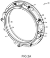
- FIG. 2A illustrates an improved carbon face seal assembly, in accordance with various embodiments
- FIG. 2B illustrates an improved carbon face seal assembly, in accordance with various embodiments
- FIG. 3 illustrates a cross section of an improved face seal assembly, in accordance with various embodiments
- FIG. 4A illustrates a disrupted surface of a seal face, in accordance with various embodiments
- FIG. 4B illustrates a patterned portion a disrupted surface of a seal face, in accordance with various embodiments
- FIG. 4C illustrates a patterned portion a disrupted surface of a seal face, in accordance with various embodiments
- FIG. 4D illustrates a patterned portion a disrupted surface of a seal face, in accordance with various embodiments
- FIG. 4E illustrates a patterned portion a disrupted surface of a seal face, in accordance with various embodiments
- FIG. 5A illustrates a white light interferometry of a patterned portion, in accordance with various embodiments.
- FIG. 5B illustrates a white light interferometry surface profile of a patterned portion, in accordance with various embodiments.
- any of the method or process descriptions may be executed in any order and are not necessarily limited to the order presented.
- any reference to singular includes plural embodiments, and any reference to more than one component or step may include a singular embodiment or step.
- any reference to attached, fixed, coupled, connected or the like may include permanent, removable, temporary, partial, full and/or any other possible attachment option.
- any reference to without contact (or similar phrases) may also include reduced contact or minimal contact. Surface shading lines may be used throughout the figures to denote different parts but not necessarily to denote the same or different materials.
- Gas turbine engine 20 may be a two-spool turbofan that generally incorporates a fan section 22 , a compressor section 24 , a combustor section 26 and a turbine section 28 .
- fan section 22 can drive air along a bypass flow-path B while compressor section 24 can drive air for compression and communication into combustor section 26 then expansion through turbine section 28 .
- turbofan gas turbine engine 20 Although depicted as a turbofan gas turbine engine 20 herein, it should be understood that the concepts described herein are not limited to use with turbofans as the teachings may be applied to other types of turbine engines including turbojet engines, a low-bypass turbofans, a high bypass turbofans, or any other gas turbine known to those skilled in the art.
- Gas turbine engine 20 may generally comprise a low speed spool 30 and a high speed spool 32 mounted for rotation about an engine central longitudinal axis A-A′ relative to an engine static structure 36 via one or more bearing systems 38 (shown as bearing system 38 - 1 and bearing system 38 - 2 ). It should be understood that various bearing systems 38 at various locations may alternatively or additionally be provided, including for example, bearing system 38 , bearing system 38 - 1 , and bearing system 38 - 2 .
- Low speed spool 30 may generally comprise an inner shaft 40 that interconnects a fan 42 , a low pressure (or first) compressor section 44 (also referred to a low pressure compressor) and a low pressure (or first) turbine section 46 .
- Inner shaft 40 may be connected to fan 42 through a geared architecture 48 that can drive fan 42 at a lower speed than low speed spool 30 .
- Geared architecture 48 may comprise a gear assembly 60 enclosed within a gear housing 62 .
- Gear assembly 60 couples inner shaft 40 to a rotating fan structure.
- High speed spool 32 may comprise an outer shaft 50 that interconnects a high pressure compressor (“HPC”) 52 (e.g., a second compressor section) and high pressure (or second) turbine section 54 .
- HPC high pressure compressor
- a combustor 56 may be located between HPC 52 and high pressure turbine 54 .
- a mid-turbine frame 57 of engine static structure 36 may be located generally between high pressure turbine 54 and low pressure turbine 46 .
- Mid-turbine frame 57 may support one or more bearing systems 38 in turbine section 28 .
- Inner shaft 40 and outer shaft 50 may be concentric and rotate via bearing systems 38 about the engine central longitudinal axis A-A′, which is collinear with their longitudinal axes.
- a “high pressure” compressor or turbine experiences a higher pressure than a corresponding “low pressure” compressor or turbine.
- the core airflow C may be compressed by low pressure compressor 44 then HPC 52 , mixed and burned with fuel in combustor 56 , then expanded over high pressure turbine 54 and low pressure turbine 46 .
- Mid-turbine frame 57 includes airfoils 59 which are in the core airflow path.
- Low pressure turbine 46 , and high pressure turbine 54 rotationally drive the respective low speed spool 30 and high speed spool 32 in response to the expansion.
- Gas turbine engine 20 may be, for example, a high-bypass geared aircraft engine. In various embodiments, the bypass ratio of gas turbine engine 20 may be greater than about six (6). In various embodiments, the bypass ratio of gas turbine engine 20 may be greater than ten (10).
- geared architecture 48 may be an epicyclic gear train, such as a star gear system (sun gear in meshing engagement with a plurality of star gears supported by a carrier and in meshing engagement with a ring gear) or other gear system. Geared architecture 48 may have a gear reduction ratio of greater than about 2.3 and low pressure turbine 46 may have a pressure ratio that is greater than about 5. In various embodiments, the bypass ratio of gas turbine engine 20 is greater than about ten (10:1).
- the diameter of fan 42 may be significantly larger than that of the low pressure compressor 44 , and the low pressure turbine 46 may have a pressure ratio that is greater than about (5:1). Low pressure turbine 46 pressure ratio may be measured prior to inlet of low pressure turbine 46 as related to the pressure at the outlet of low pressure turbine 46 prior to an exhaust nozzle. It should be understood, however, that the above parameters are exemplary of various embodiments of a suitable geared architecture engine and that the present disclosure contemplates other gas turbine engines including direct drive turbofans.
- next generation of turbofan engines may be designed for higher efficiency which is associated with higher pressure ratios and higher temperatures in the HPC 52 .
- These higher operating temperatures and pressure ratios may create operating environments that may cause thermal loads that are higher than the thermal loads encountered in conventional turbofan engines, which may shorten the operational life of current components.
- HPC 52 may comprise alternating rows of rotating rotors and stationary stators.
- Stators may have a cantilevered configuration or a shrouded configuration.
- a stator may comprise a stator vane, a casing support and a hub support.
- a stator vane may be supported along an outer diameter by a casing support and along an inner diameter by a hub support.
- a cantilevered stator may comprise a stator vane that is only retained and/or supported at the casing (e.g., along an outer diameter).
- rotors may be configured to compress and spin a fluid flow.
- Stators may be configured to receive and straighten the fluid flow.
- the fluid flow discharged from the trailing edge of stators may be straightened (e.g., the flow may be directed in a substantially parallel path to the centerline of the engine and/or HPC) to increase and/or improve the efficiency of the engine and, more specifically, to achieve maximum and/or near maximum compression and efficiency when the straightened air is compressed and spun by rotor 64 .
- a gas turbine engine such as gas turbine engine 20 may comprise an improved carbon face seal assembly 200 .
- Improved carbon face seal assembly 200 comprises a primary seal 202 which may be press fit into seal housing 204 .
- Seal housing 204 has an annular extrusion 206 disposed within seal support 208 .
- seal support 208 may comprise alignment pins 210 extending axially outward from forward face 230 of seal support 208 and spring pockets 228 cut axially inward of forward face 230 .
- seal housing 204 may comprise spring tabs 224 coupled to coil springs 226 and alignment tabs 212 having alignment channels 214 .
- sleeves 216 may be disposed over alignment pins 210 and comprise a flat portion 232 configured to interface with a corresponding flat portion of inner surface 234 of alignment channels 214 .
- seal housing 204 is aligned circumferentially with seal support 208 when alignment pins 210 are disposed within alignment channels 241 and flat portion 232 is in contact with inner surface 234 .
- annular extrusion 206 may be slid axially inward toward forward face 230 and coil springs 226 may be disposed within spring pockets 228 tending thereby to compress coil springs 226 .
- flange 218 is fitted against sleeve 216 over a distal end of alignment pin 210 .
- flange 218 is coupled to alignment pin 210 by cotter pin 220 and an interference between flange 218 and forward face 222 of alignment tab 212 tends to inhibit seal housing 204 and annular extrusion 206 from backing out seal support 208 .
- improved carbon face seal assembly 200 is shown in cross section as installed in a gas turbine engine such as gas turbine engine 20 . Improved carbon face seal assembly 200 is coupled to case 326 at seal support 208 .
- a shaft 320 comprising a seal seat 312 is disposed within the annulus of annular extrusion 206 of seal housing 204 .
- primary seal 202 comprises a seal material 300 having an inner diameter 304 , an outer diameter 306 , a sealing face 308 , and a base 310 .
- a step 328 may be cut inward from outer diameter 306 toward inner diameter 304 and sealing face 308 may be defined between step 328 and the inner diameter 304 .
- seal housing 204 may comprise a secondary seal 316 at a distal end of annular extrusion 206 opposite primary seal 202 .
- secondary seal 316 may seal against seal support 208 .
- coil springs 226 may impart a spring force F s upon seal housing 204 driving seal housing axially away from seal support 208 and relatively toward seal seat 312 tending thereby to drive sealing face 308 of primary seal 202 into contact with seating face 314 of seal seat 312 .
- primary seal 202 may divide a high pressure compartment 322 and a low pressure compartment 324 .
- sealing face 308 of primary seal 202 is contacted with seal seat 312 at seating face 314 .
- shaft 320 begins axial rotation (X-axis) thereby rotating seal seat 312 and seating face 314 against sealing face 308 of primary seal 202 .
- Primary seal 202 is held fixed by seal housing 204 and seal support 208 .
- As seating face 314 beings to rotate against sealing face 308 a friction force therebetween tends to increase thereby tending to contribute to wearing of primary seal 202 at sealing face 308 .
- sealing face 308 may comprise a disrupted surface 400 .
- Disrupted surface 400 tends to promote transfer of seal material 300 from sealing face 308 to seating face 314 in response to rotation of the seating face 314 against the sealing face 308 .
- the friction force therebetween tends to decrease.
- disrupted surface 400 tends to improve the wear characteristics of primary seal 202 .
- disrupted surface 400 may be formed by any suitable method such as, for example, lapping, milling, grinding, media blasting, etching, ablation, and/or the like.
- disrupted surface 400 may comprise patterned portions defined by, for example, ablation, etching, abrasions, and/or the like.
- Disrupted surface may include a radially patterned portion 402 , a circumferentially patterned portion 404 , a hatch pattern portion 406 , and/or a cross-hatch pattern portion 408 .
- Patterned portions ( 402 , 404 , 406 , 408 ) may be formed, for example, by regular laser ablation of sealing face 308 leaving ablated portions (illustrated as lines) relatively below the sealing face 308 .
- a patterned portion may comprise a plurality of ablated portions.
- a baseline surface or nominally smooth surface may have an Ra less than 0.254 ⁇ m [10 ⁇ inch].
- a measured Ra of a nominally smooth surface may be between 0.051 ⁇ m [2 ⁇ inch] and 0.762 ⁇ m [3 ⁇ inch].
- the measured Rz of a nominally smooth surface may be between 0.508 ⁇ m [20 ⁇ inch] to 2.03 ⁇ m [80 ⁇ inch] or may be between 0.508 ⁇ m [20 ⁇ inch] and 1.27 ⁇ m [50 ⁇ inch].
- a laser ablation apparatus may supply laser light and provide a configurable laser light output which may affect the spacing and depth of the ablated portions.
- the power output of the laser ablation apparatus may be between 10 watts and 30 watts.
- the resolution of the laser ablation apparatus may be between 0.025 ⁇ m [1 ⁇ inch] and 0.127 ⁇ m [5 ⁇ inch] and the beam diameter may be 2.03 ⁇ m [80 ⁇ inch].
- the scanning frequency may be configured between 0 kHz and 60 kHz.
- the spacing between ablated portions may be configured between 0.08 mm [0.0031 in.] 0.25 mm and [0.009 in.].
- the wavelength of the laser light may be between 0.231 ⁇ m [9.1 ⁇ inch] and 0.277 ⁇ m [10.9 ⁇ inch].
- the ablation depth may be configured between 0.381 ⁇ m [15 ⁇ inch] to 12.7 ⁇ m [500 ⁇ inch], or may be configured between 2.54 ⁇ m [100 ⁇ inch] to 10.2 ⁇ m [400 ⁇ inch], or may be configured between 3.81 ⁇ m [150 ⁇ inch] and 6.35 ⁇ m [250 ⁇ inch].
- the beam dwell time of the laser light may be configurable.
- the laser light output may be configured in accordance with TABLE 1 below.
- column one provides a range of laser ablation apparatus power selections as a percentage of a 25 W output power.
- Column two provides a selection of scanning speeds of the laser light in mm/sec.
- Column three provides a selection of frequencies in KHz for a laser pulse firing frequency which may be selectable between 0 KHz and 400 KHz.
- Column four provides a scan diameter in mm below the laser beam focal point.
- Column five provides a selected spacing of the ablated portions.
- Column six shows the associated average surface roughness Ra in pinch for the laser ablation apparatus settings of columns 1 - 5 .
- the Ra describes a mean line across the plurality of ablated portions such that the areas above and below the mean line are within a desired tolerance.
- Column six shows the associated average peak-to-valley surface roughness Rz in pinch for the laser ablation apparatus settings of columns 1 - 5 .
- the Rz describes an average of the five greatest peak-to-valley distances of the ablated portions.
- FIGS. 5A and 5B an exemplary patterned portion 500 of disrupted surface 400 are shown under white light interferometry.
- FIG. 5A illustrates the relative depth (in ⁇ in below the sealing face 308 ) of ablated portions 502 corresponding to the 40% power setting and 200 mm/sec scanning speed of TABLE 1.
- FIG. 5B illustrates a graph of the surface profile along the disrupted surface between the ablated portions 502 with the X-axis showing the height (in ⁇ in) of the ablated portions relative to the Ra line (dashed line marked at 0.00) and the Y-axis showing the relative distance (in ⁇ in) between ablated portions from the origin.
- references to “various embodiments,” “one embodiment,” “an embodiment,” “an example embodiment,” etc. indicate that the embodiment described may include a particular feature, structure, or characteristic, but every embodiment may not necessarily include the particular feature, structure, or characteristic. Moreover, such phrases are not necessarily referring to the same embodiment. Further, when a particular feature, structure, or characteristic is described in connection with an embodiment, it is submitted that it is within the knowledge of one skilled in the art to affect such feature, structure, or characteristic in connection with other embodiments whether or not explicitly described. After reading the description, it will be apparent to one skilled in the relevant art(s) how to implement the disclosure in alternative embodiments.
Landscapes
- Engineering & Computer Science (AREA)
- General Engineering & Computer Science (AREA)
- Mechanical Engineering (AREA)
- Chemical & Material Sciences (AREA)
- Combustion & Propulsion (AREA)
- Sealing Using Fluids, Sealing Without Contact, And Removal Of Oil (AREA)
- Sealing Devices (AREA)
Abstract
Description
| TABLE 1 |
| Laser Ablation Apparatus Settings |
| INPUTS |
| Scanning | Scan Diameter | OUTPUTS |
| Power | Speed | Frequency | [mm below | Spacing | Ra | Rz |
| [% max] | [mm/sec] | [KHz] | focal point] | [mm] | [μinch] | [μinch] |
| 40 | 200 | 20 | −2 | 0.14 | 50.347 | 236.680 |
| 40 | 200 | 20 | −2 | 0.08 | 39.673 | 255.910 |
| 20 | 200 | 20 | −2 | 0.08 | 34.079 | 194.160 |
| 20 | 200 | 60 | −2 | 0.08 | 25.091 | 139.080 |
| 20 | 1000 | 20 | −2 | 0.08 | 19.144 | 114.910 |
| 20 | 1000 | 60 | −2 | 0.08 | 18.540 | 94.510 |
| 40 | 100 | 20 | −2 | 0.08 | 100.843 | 412.830 |
| 40 | 200 | 20 | −2 | 0.25 | 52.498 | 220.270 |
| 40 | 200 | 20 | −6 | 0.08 | 20.340 | 120.740 |
| 40 | 1000 | 20 | −2 | 0.08 | 15.664 | 98.300 |
| 60 | 200 | 20 | −6 | 0.14 | 20.101 | 148.880 |
| 60 | 200 | 20 | −6 | 0.08 | 22.939 | 124.640 |
| 80 | 100 | 0 | −2 | 0.08 | 21.884 | 127.520 |
| 80 | 200 | 20 | −6 | 0.08 | 25.830 | 207.110 |
Claims (10)
Priority Applications (2)
| Application Number | Priority Date | Filing Date | Title |
|---|---|---|---|
| US16/293,383 US11255205B2 (en) | 2019-03-05 | 2019-03-05 | Systems and methods for improving start up wear performance of carbon seals |
| EP20160762.9A EP3705760A3 (en) | 2019-03-05 | 2020-03-03 | Systems and methods for improving start up wear performance of carbon seals |
Applications Claiming Priority (1)
| Application Number | Priority Date | Filing Date | Title |
|---|---|---|---|
| US16/293,383 US11255205B2 (en) | 2019-03-05 | 2019-03-05 | Systems and methods for improving start up wear performance of carbon seals |
Publications (2)
| Publication Number | Publication Date |
|---|---|
| US20200284155A1 US20200284155A1 (en) | 2020-09-10 |
| US11255205B2 true US11255205B2 (en) | 2022-02-22 |
Family
ID=69770529
Family Applications (1)
| Application Number | Title | Priority Date | Filing Date |
|---|---|---|---|
| US16/293,383 Active 2039-07-29 US11255205B2 (en) | 2019-03-05 | 2019-03-05 | Systems and methods for improving start up wear performance of carbon seals |
Country Status (2)
| Country | Link |
|---|---|
| US (1) | US11255205B2 (en) |
| EP (1) | EP3705760A3 (en) |
Families Citing this family (1)
| Publication number | Priority date | Publication date | Assignee | Title |
|---|---|---|---|---|
| US12515807B2 (en) | 2024-01-19 | 2026-01-06 | Pratt & Whitney Canada Corp. | Bolted connection between mounting bracket and aircraft engine case(s) |
Citations (9)
| Publication number | Priority date | Publication date | Assignee | Title |
|---|---|---|---|---|
| US5501470A (en) | 1992-12-11 | 1996-03-26 | Nippon Pillar Packing Co., Ltd. | Non-contacting shaft sealing device with grooved face pattern |
| US20060033286A1 (en) | 2004-07-29 | 2006-02-16 | Coorstek, Inc. | Graphite loaded PTFE mechanical seals for rotating shafts |
| US7194803B2 (en) | 2001-07-05 | 2007-03-27 | Flowserve Management Company | Seal ring and method of forming micro-topography ring surfaces with a laser |
| US8167545B2 (en) | 2008-02-27 | 2012-05-01 | United Technologies Corp. | Self-balancing face seals and gas turbine engine systems involving such seals |
| US20140294331A1 (en) | 2010-10-06 | 2014-10-02 | Eagle Industry Co., Ltd. | Sliding component |
| US9383017B2 (en) * | 2011-03-15 | 2016-07-05 | Flowserve Management Company | Tapered channel macro/micro feature for mechanical face seals |
| US20160333711A1 (en) * | 2014-01-08 | 2016-11-17 | United Technologies Corporation | Flanged spring guide for a face seal arrangement |
| US9964216B2 (en) * | 2012-05-21 | 2018-05-08 | Eagle Industry Co., Ltd. | Sliding component |
| EP3438417A1 (en) | 2017-08-01 | 2019-02-06 | United Technologies Corporation | Face seal arrangement |
-
2019
- 2019-03-05 US US16/293,383 patent/US11255205B2/en active Active
-
2020
- 2020-03-03 EP EP20160762.9A patent/EP3705760A3/en active Pending
Patent Citations (9)
| Publication number | Priority date | Publication date | Assignee | Title |
|---|---|---|---|---|
| US5501470A (en) | 1992-12-11 | 1996-03-26 | Nippon Pillar Packing Co., Ltd. | Non-contacting shaft sealing device with grooved face pattern |
| US7194803B2 (en) | 2001-07-05 | 2007-03-27 | Flowserve Management Company | Seal ring and method of forming micro-topography ring surfaces with a laser |
| US20060033286A1 (en) | 2004-07-29 | 2006-02-16 | Coorstek, Inc. | Graphite loaded PTFE mechanical seals for rotating shafts |
| US8167545B2 (en) | 2008-02-27 | 2012-05-01 | United Technologies Corp. | Self-balancing face seals and gas turbine engine systems involving such seals |
| US20140294331A1 (en) | 2010-10-06 | 2014-10-02 | Eagle Industry Co., Ltd. | Sliding component |
| US9383017B2 (en) * | 2011-03-15 | 2016-07-05 | Flowserve Management Company | Tapered channel macro/micro feature for mechanical face seals |
| US9964216B2 (en) * | 2012-05-21 | 2018-05-08 | Eagle Industry Co., Ltd. | Sliding component |
| US20160333711A1 (en) * | 2014-01-08 | 2016-11-17 | United Technologies Corporation | Flanged spring guide for a face seal arrangement |
| EP3438417A1 (en) | 2017-08-01 | 2019-02-06 | United Technologies Corporation | Face seal arrangement |
Non-Patent Citations (3)
| Title |
|---|
| European Patent Office, European Office Action dated Aug. 27, 2020 in Application No. 20160762.9. |
| European Patent Office, European Search Report dated Dec. 14, 2020 in Application No. 20160762.9. |
| Surface Roughness Conversion Chart Tables—Engineers Edge—accessed online on Sep. 23, 2020 (Year: 2020). * |
Also Published As
| Publication number | Publication date |
|---|---|
| US20200284155A1 (en) | 2020-09-10 |
| EP3705760A2 (en) | 2020-09-09 |
| EP3705760A3 (en) | 2021-01-13 |
Similar Documents
| Publication | Publication Date | Title |
|---|---|---|
| US8356975B2 (en) | Gas turbine engine with non-axisymmetric surface contoured vane platform | |
| US11029027B2 (en) | Dilution/effusion hole pattern for thick combustor panels | |
| US20180306437A1 (en) | Fuel swirler with anti-rotation features | |
| US10364688B2 (en) | Minidisk balance flange | |
| US20190178381A1 (en) | Face seal arrangement with air load force balance recovery for improved failure mitigation strategies | |
| US10934845B2 (en) | Dual cooling airflow to blades | |
| US10823012B2 (en) | Fastener openings for stress distribution | |
| US6250878B1 (en) | Method and assembly for connecting air ducts in gas turbine engines | |
| EP3112615B1 (en) | Compressor section with a particular arrangement to hold a vane | |
| US11085332B2 (en) | BOAS retention assembly with interlocking ring structures | |
| US11255205B2 (en) | Systems and methods for improving start up wear performance of carbon seals | |
| US10808558B2 (en) | Support ring with thermal heat shield for case flange | |
| US20240352942A1 (en) | Tandem blade rotor disk | |
| US12018567B2 (en) | Joint between gas turbine engine components with bonded fastener(s) | |
| US10619498B2 (en) | Fan exit stator assembly | |
| US10746041B2 (en) | Shroud and shroud assembly process for variable vane assemblies | |
| US20190112935A1 (en) | Gap closing wearliner | |
| US10865650B2 (en) | Stator vane support with anti-rotation features |
Legal Events
| Date | Code | Title | Description |
|---|---|---|---|
| AS | Assignment |
Owner name: UNITED TECHNOLOGIES CORPORATION, CONNECTICUT Free format text: ASSIGNMENT OF ASSIGNORS INTEREST;ASSIGNORS:RANGANATH, SANTOSH;KILGUSS, ANDREW C.;OGDEN, WILLIAM P.;AND OTHERS;SIGNING DATES FROM 20190228 TO 20190304;REEL/FRAME:048510/0102 |
|
| FEPP | Fee payment procedure |
Free format text: ENTITY STATUS SET TO UNDISCOUNTED (ORIGINAL EVENT CODE: BIG.); ENTITY STATUS OF PATENT OWNER: LARGE ENTITY |
|
| STPP | Information on status: patent application and granting procedure in general |
Free format text: NON FINAL ACTION MAILED |
|
| STPP | Information on status: patent application and granting procedure in general |
Free format text: RESPONSE TO NON-FINAL OFFICE ACTION ENTERED AND FORWARDED TO EXAMINER |
|
| STPP | Information on status: patent application and granting procedure in general |
Free format text: FINAL REJECTION MAILED |
|
| STPP | Information on status: patent application and granting procedure in general |
Free format text: RESPONSE AFTER FINAL ACTION FORWARDED TO EXAMINER |
|
| STPP | Information on status: patent application and granting procedure in general |
Free format text: ADVISORY ACTION MAILED |
|
| STPP | Information on status: patent application and granting procedure in general |
Free format text: DOCKETED NEW CASE - READY FOR EXAMINATION |
|
| STPP | Information on status: patent application and granting procedure in general |
Free format text: NON FINAL ACTION MAILED |
|
| AS | Assignment |
Owner name: RAYTHEON TECHNOLOGIES CORPORATION, CONNECTICUT Free format text: CHANGE OF NAME;ASSIGNOR:UNITED TECHNOLOGIES CORPORATION;REEL/FRAME:057190/0719 Effective date: 20200403 |
|
| AS | Assignment |
Owner name: RAYTHEON TECHNOLOGIES CORPORATION, CONNECTICUT Free format text: CORRECTIVE ASSIGNMENT TO CORRECT THE SPELLING ON THE ADDRESS 10 FARM SPRINGD ROAD FARMINGTONCONNECTICUT 06032 PREVIOUSLY RECORDED ON REEL 057190 FRAME 0719. ASSIGNOR(S) HEREBY CONFIRMS THE CORRECT SPELLING OF THE ADDRESS 10 FARM SPRINGS ROAD FARMINGTON CONNECTICUT 06032;ASSIGNOR:UNITED TECHNOLOGIES CORPORATION;REEL/FRAME:057226/0390 Effective date: 20200403 |
|
| STPP | Information on status: patent application and granting procedure in general |
Free format text: RESPONSE TO NON-FINAL OFFICE ACTION ENTERED AND FORWARDED TO EXAMINER |
|
| STPP | Information on status: patent application and granting procedure in general |
Free format text: NOTICE OF ALLOWANCE MAILED -- APPLICATION RECEIVED IN OFFICE OF PUBLICATIONS |
|
| STCF | Information on status: patent grant |
Free format text: PATENTED CASE |
|
| AS | Assignment |
Owner name: RTX CORPORATION, CONNECTICUT Free format text: CHANGE OF NAME;ASSIGNOR:RAYTHEON TECHNOLOGIES CORPORATION;REEL/FRAME:064714/0001 Effective date: 20230714 |
|
| MAFP | Maintenance fee payment |
Free format text: PAYMENT OF MAINTENANCE FEE, 4TH YEAR, LARGE ENTITY (ORIGINAL EVENT CODE: M1551); ENTITY STATUS OF PATENT OWNER: LARGE ENTITY Year of fee payment: 4 |