US11249804B2 - Affinity based optimization of virtual persistent memory volumes - Google Patents
Affinity based optimization of virtual persistent memory volumes Download PDFInfo
- Publication number
- US11249804B2 US11249804B2 US16/594,873 US201916594873A US11249804B2 US 11249804 B2 US11249804 B2 US 11249804B2 US 201916594873 A US201916594873 A US 201916594873A US 11249804 B2 US11249804 B2 US 11249804B2
- Authority
- US
- United States
- Prior art keywords
- virtual
- pmem
- cpu
- computer
- devices
- Prior art date
- Legal status (The legal status is an assumption and is not a legal conclusion. Google has not performed a legal analysis and makes no representation as to the accuracy of the status listed.)
- Active, expires
Links
Images


Classifications
-
- G—PHYSICS
- G06—COMPUTING OR CALCULATING; COUNTING
- G06F—ELECTRIC DIGITAL DATA PROCESSING
- G06F9/00—Arrangements for program control, e.g. control units
- G06F9/06—Arrangements for program control, e.g. control units using stored programs, i.e. using an internal store of processing equipment to receive or retain programs
- G06F9/44—Arrangements for executing specific programs
- G06F9/455—Emulation; Interpretation; Software simulation, e.g. virtualisation or emulation of application or operating system execution engines
- G06F9/45533—Hypervisors; Virtual machine monitors
- G06F9/45558—Hypervisor-specific management and integration aspects
-
- G—PHYSICS
- G06—COMPUTING OR CALCULATING; COUNTING
- G06F—ELECTRIC DIGITAL DATA PROCESSING
- G06F16/00—Information retrieval; Database structures therefor; File system structures therefor
- G06F16/10—File systems; File servers
- G06F16/18—File system types
- G06F16/182—Distributed file systems
-
- G—PHYSICS
- G06—COMPUTING OR CALCULATING; COUNTING
- G06F—ELECTRIC DIGITAL DATA PROCESSING
- G06F9/00—Arrangements for program control, e.g. control units
- G06F9/06—Arrangements for program control, e.g. control units using stored programs, i.e. using an internal store of processing equipment to receive or retain programs
- G06F9/46—Multiprogramming arrangements
- G06F9/50—Allocation of resources, e.g. of the central processing unit [CPU]
- G06F9/5005—Allocation of resources, e.g. of the central processing unit [CPU] to service a request
- G06F9/5011—Allocation of resources, e.g. of the central processing unit [CPU] to service a request the resources being hardware resources other than CPUs, Servers and Terminals
- G06F9/5016—Allocation of resources, e.g. of the central processing unit [CPU] to service a request the resources being hardware resources other than CPUs, Servers and Terminals the resource being the memory
-
- G—PHYSICS
- G06—COMPUTING OR CALCULATING; COUNTING
- G06F—ELECTRIC DIGITAL DATA PROCESSING
- G06F9/00—Arrangements for program control, e.g. control units
- G06F9/06—Arrangements for program control, e.g. control units using stored programs, i.e. using an internal store of processing equipment to receive or retain programs
- G06F9/46—Multiprogramming arrangements
- G06F9/50—Allocation of resources, e.g. of the central processing unit [CPU]
- G06F9/5005—Allocation of resources, e.g. of the central processing unit [CPU] to service a request
- G06F9/5027—Allocation of resources, e.g. of the central processing unit [CPU] to service a request the resource being a machine, e.g. CPUs, Servers, Terminals
-
- G—PHYSICS
- G06—COMPUTING OR CALCULATING; COUNTING
- G06F—ELECTRIC DIGITAL DATA PROCESSING
- G06F9/00—Arrangements for program control, e.g. control units
- G06F9/06—Arrangements for program control, e.g. control units using stored programs, i.e. using an internal store of processing equipment to receive or retain programs
- G06F9/46—Multiprogramming arrangements
- G06F9/50—Allocation of resources, e.g. of the central processing unit [CPU]
- G06F9/5061—Partitioning or combining of resources
- G06F9/5077—Logical partitioning of resources; Management or configuration of virtualized resources
-
- G—PHYSICS
- G06—COMPUTING OR CALCULATING; COUNTING
- G06F—ELECTRIC DIGITAL DATA PROCESSING
- G06F9/00—Arrangements for program control, e.g. control units
- G06F9/06—Arrangements for program control, e.g. control units using stored programs, i.e. using an internal store of processing equipment to receive or retain programs
- G06F9/44—Arrangements for executing specific programs
- G06F9/455—Emulation; Interpretation; Software simulation, e.g. virtualisation or emulation of application or operating system execution engines
- G06F9/45533—Hypervisors; Virtual machine monitors
- G06F9/45558—Hypervisor-specific management and integration aspects
- G06F2009/45562—Creating, deleting, cloning virtual machine instances
-
- G—PHYSICS
- G06—COMPUTING OR CALCULATING; COUNTING
- G06F—ELECTRIC DIGITAL DATA PROCESSING
- G06F9/00—Arrangements for program control, e.g. control units
- G06F9/06—Arrangements for program control, e.g. control units using stored programs, i.e. using an internal store of processing equipment to receive or retain programs
- G06F9/44—Arrangements for executing specific programs
- G06F9/455—Emulation; Interpretation; Software simulation, e.g. virtualisation or emulation of application or operating system execution engines
- G06F9/45533—Hypervisors; Virtual machine monitors
- G06F9/45558—Hypervisor-specific management and integration aspects
- G06F2009/45579—I/O management, e.g. providing access to device drivers or storage
-
- G—PHYSICS
- G06—COMPUTING OR CALCULATING; COUNTING
- G06F—ELECTRIC DIGITAL DATA PROCESSING
- G06F9/00—Arrangements for program control, e.g. control units
- G06F9/06—Arrangements for program control, e.g. control units using stored programs, i.e. using an internal store of processing equipment to receive or retain programs
- G06F9/44—Arrangements for executing specific programs
- G06F9/455—Emulation; Interpretation; Software simulation, e.g. virtualisation or emulation of application or operating system execution engines
- G06F9/45533—Hypervisors; Virtual machine monitors
- G06F9/45558—Hypervisor-specific management and integration aspects
- G06F2009/45583—Memory management, e.g. access or allocation
-
- G—PHYSICS
- G06—COMPUTING OR CALCULATING; COUNTING
- G06F—ELECTRIC DIGITAL DATA PROCESSING
- G06F2209/00—Indexing scheme relating to G06F9/00
- G06F2209/50—Indexing scheme relating to G06F9/50
- G06F2209/5012—Processor sets
Definitions
- the present invention relates generally to data processing systems, and more particularly, to affinity based optimization of virtual persistent memory volumes.
- PMEM persistent memory
- An embodiment includes a computer-implemented method for affinity based optimization of persistent memory volumes.
- a total memory capacity is apportioned amongst virtual persistent memory (PMEM) resources and physical memory resources.
- a set of virtual central processor unit (CPU) sockets are assigned. Each virtual CPU socket is configured based on at least one physical central processor unit (CPU) core in conjunction with a subset of the virtual PMEM and physical memory resources.
- child virtual PMEM devices are created for respective ones of the set of virtual CPU sockets, each child virtual PMEM device of the set of child virtual PMEM devices being dedicated to the parent virtual PMEM device.
- An embodiment includes a computer usable program product.
- the computer usable program product includes one or more computer-readable storage devices.
- Program instructions stored on at least one of the one or more storage devices are executable in one or more processors to provide affinity based optimization of persistent memory volumes.
- An embodiment includes a computer system.
- the computer system includes one or more processors, one or more computer-readable memories, and one or more computer-readable storage devices.
- Program instructions stored on at least one of the one or more storage devices for execution by at least one of the one or more processors via at least one of the one or more memories.
- the program instructions are executable in the one or more processors to provide affinity based optimization of persistent memory volumes.
- FIG. 1 depicts a block diagram of a network of data processing systems in which illustrative embodiments are implemented
- FIG. 2 depicts a block diagram of a data processing system in which illustrative embodiments are implemented
- FIG. 5 depicts a flowchart of an example process for affinity based optimization of virtual persistent memory volumes
- FIG. 6 depicts a flowchart of a further example process for affinity based optimization of virtual persistent memory volumes
- FIG. 7 depicts a flowchart of another example process for affinity based optimization of virtual persistent memory volumes.
- a user interface for creating a virtual PMEM device would allow for the creation of a device with a given capacity without specifying which DRAM in the physical server will be used for backing the device.
- the amount of DRAM on each CPU socket available for virtual PMEM devices could be displayed and selected by the user.
- this exposes the user to additional complexity, requiring the user to understand guest placement, including which CPU sockets their IO adapters are attached to, and places the burden on the user to create the virtual PMEM devices on the correct CPU sockets.
- Embodiments herein eliminate or minimize the problems of the latter solution and provide a mechanism for simplifying the user experience.
- Embodiments presented herein advantageously provide optimal virtual PMEM device affinity without exposing the user to additional complexity.
- affinity refers to, and indicates, an access proximity of physical memory to physical central processor unit (CPU) cores for a particular virtual node.
- the virtual nodes in embodiments herein relates to a virtual CPU socket.
- the affinity characteristic as used herein is measurable as a ratio of the physical memory to the physical CPU cores that are assigned to a particular virtual CPU socket.
- the illustrative embodiments recognize that the presently available tools or solutions do not address these needs or provide adequate solutions for these needs.
- the illustrative embodiments used to describe the invention generally address and solve the above-described problems and other problems related to of optimizing placement of virtual PMEM devices by creating child virtual PMEM devices per the appropriate CPU sockets and informing a workload of their placement.
- An embodiment can be implemented as a hypervisor application constituted of any combination of hardware and software program instructions.
- the application implementing an embodiment can be configured as a modification of an existing server computing device or system, as a separate application that operates in conjunction with a server device, or some combination thereof.
- a method of an embodiment described herein when implemented to execute on a device or data processing system, comprises substantial advancement of the functionality of that device or data processing system in optimizing placement of virtual PMEM devices.
- the placement of virtual PMEM devices is based on creating child virtual PMEM devices in accordance with generation of affinity based CPU sockets and informing a workload of their placement, thereby facilitating implementation of a virtualization solution that efficiently allocates virtual PMEM devices and related CPU resources for workloads where strong CPU affinity is critical for workload performance.
- a virtual PMEM device when configuring a virtual PMEM device for a guest, the user follows workload specific guidelines to create a single parent virtual PMEM device of a requested capacity. Each parent virtual PMEM device will be assigned a unique identifier (GUID). A mix of physical memory and virtual PMEM is apportioned based on a ratio of physical to virtual PMEM that the hypervisor assigns.
- CPU sockets are generated and assigned by the hypervisor taking into account affinity characteristics in relation to physical and virtual resources, both CPU and memory.
- Each virtual CPU socket is configured based on at least one physical central processor unit (CPU) core in conjunction with a subset of the virtual PMEM and physical memory resources.
- CPU central processor unit
- the hypervisor applies an affinity optimization algorithm to determine optimally assignment of physical CPU cores and DRAM capacity to the guest based on the total DRAM requirements.
- the amount of DRAM available for virtual PMEM usage can be dynamically adjusted based on an amount of DRAM connected and assigned to each CPU socket, the amount of DRAM assigned to guest functions by the hypervisor managing a given CPU socket, and the amount of DRAM assigned to each CPU socket being used by the system firmware.
- Child virtual PMEMs are created in association with CPU sockets. Each of the child virtual PMEM devices is dedicated to the parent virtual PMEM device.
- the hypervisor informs the workload of the physical and virtual resource placements in accordance with the CPU sockets and child virtual PMEMs. The GUID is applied to identify the virtual PMEM device provisioned for the workload.
- the hypervisor after determining the proper placement of the guest to maintain the best possible affinity characteristics, creates a child virtual PMEM device for a given parent virtual PMEM device for each of the created CPU sockets having DRAM and CPU cores assigned to the guest.
- the size of each child virtual PMEM device is based on the ratio of DRAM required for the parent virtual PMEM devices and the normal DRAM assignment.
- the guest receives 50 GB of normal DRAM and a 50 GB child virtual PMEM device on one CPU socket and 75 GB of normal DRAM and a 75 GB child virtual PMEM device on each of the other two CPU sockets
- the illustrative embodiments are described with respect to certain types of physical memory such as including, but not limited to DRAM, virtual memory including PMEM, hypervisor applications that are constituted of any combination of hardware and software program instructions, including hypervisor applications installed on server devices and systems, physical CPU cores, virtual CPU, server devices, data processing systems, environments, components, and applications only as examples. Any specific manifestations of these and other similar artifacts are not intended to be limiting to the invention. Any suitable manifestation of these and other similar artifacts can be selected within the scope of the illustrative embodiments.
- the illustrative embodiments may be implemented with respect to any type of data, data source, or access to a data source over a data network.
- Any type of data storage device may provide the data to an embodiment of the invention, either locally at a data processing system or over a data network, within the scope of the invention.
- any type of data storage device suitable for use with the server device may provide the data to such embodiment, either locally at the mobile device or over a data network, within the scope of the illustrative embodiments.
- the illustrative embodiments are described using specific code, designs, architectures, protocols, layouts, schematics, and tools only as examples and are not limiting to the illustrative embodiments. Furthermore, the illustrative embodiments are described in some instances using particular software, tools, and data processing environments only as an example for the clarity of the description. The illustrative embodiments may be used in conjunction with other comparable or similarly purposed structures, systems, applications, or architectures. For example, other comparable mobile devices, structures, systems, applications, or architectures therefor, may be used in conjunction with such embodiment of the invention within the scope of the invention. An illustrative embodiment may be implemented in hardware, software, or a combination thereof.
- FIGS. 1 and 2 are example diagrams of data processing environments in which illustrative embodiments are implemented.
- FIGS. 1 and 2 are only examples and are not intended to assert or imply any limitation with regard to the environments in which different embodiments are implemented.
- a particular implementation may make many modifications to the depicted environments based on the following description.
- FIG. 1 depicts a block diagram of a network of data processing systems in which illustrative embodiments are implemented.
- Data processing environment 100 is a network of computers in which the illustrative embodiments are implemented.
- Data processing environment 100 includes network 102 .
- Network 102 is the medium used to provide communications links between various devices and computers connected together within data processing environment 100 .
- Network 102 may include connections, such as wire, wireless communication links, or fiber optic cables.
- Clients or servers are only example roles of certain data processing systems connected to network 102 and are not intended to exclude other configurations or roles for these data processing systems.
- Server 104 and server 106 couple to network 102 along with storage unit 108 .
- Software applications may execute on any computer in data processing environment 100 .
- Clients 112 , 114 are also coupled to network 102 .
- a data processing system, such as server 104 or 106 , or clients 112 , 114 may contain data and may have software applications or software tools executing thereon.
- FIG. 1 depicts certain components that are usable in an example implementation of an embodiment.
- servers 104 and 106 , and clients 112 , 114 are depicted as servers and clients only as example and not to imply a limitation to a client-server architecture.
- an embodiment can be distributed across several data processing systems and a data network as shown, whereas another embodiment can be implemented on a single data processing system within the scope of the illustrative embodiments.
- Data processing systems 104 , 106 , and 114 also represent example nodes in a cluster, partitions, and other configurations suitable for implementing an embodiment.
- Device 132 is an example of a mobile devices described herein.
- device 132 can take the form of a smartphone, a tablet computer, a laptop computer, client 110 in a portable form, a wearable computing device, or any other suitable device.
- Any software application described as executing in another data processing system in FIG. 1 can be configured to execute in device 132 in a similar manner.
- Any data or information stored or produced in another data processing system in FIG. 1 can be configured to be stored or produced in device 132 in a similar manner.
- Hypervisor 105 implements an embodiment described herein.
- Hypervisor can be comprised of any combination of hardware and software program instructions executable in one or more processors.
- Hypervisor 105 can execute in servers 104 and 106 , storage unit 108 , and clients 112 , 114 coupled to network 102 using wired connections, wireless communication protocols, or other suitable data connectivity.
- Clients 112 , 114 may be, for example, a portable personal computer.
- server 104 provides data, such as boot files, operating system images, and applications to clients 112 , 114 .
- Clients 112 , 114 and devices 132 , 134 may be clients to server 104 in this example.
- Clients 112 , 114 as well as devices 132 , 134 may include their own data, boot files, operating system images, and applications.
- Data processing environment 100 may include additional servers, clients, and other devices that are not shown.
- data processing environment 100 may be the Internet.
- Network 102 may represent a collection of networks and gateways that use the Transmission Control Protocol/Internet Protocol (TCP/IP) and other protocols to communicate with one another.
- TCP/IP Transmission Control Protocol/Internet Protocol
- At the heart of the Internet is a backbone of data communication links between major nodes or host computers, including thousands of commercial, governmental, educational, and other computer systems that route data and messages.
- data processing environment 100 also may be implemented as a number of different types of networks, such as for example, an intranet, a local area network (LAN), or a wide area network (WAN).
- FIG. 1 is intended as an example, and not as an architectural limitation for the different illustrative embodiments.
- data processing environment 100 may be used for implementing a client-server environment in which the illustrative embodiments may be implemented.
- a client-server environment enables software applications and data to be distributed across a network such that an application functions by using the interactivity between a client data processing system and a server data processing system.
- Data processing environment 100 may also employ a service oriented architecture where interoperable software components distributed across a network may be packaged together as coherent business applications.
- Data processing environment 100 may also take the form of a cloud, and employ a cloud computing model of service delivery for enabling convenient, on-demand network access to a shared pool of configurable computing resources (e.g. networks, network bandwidth, servers, processing, memory, storage, applications, virtual machines, and services) that can be rapidly provisioned and released with minimal management effort or interaction with a provider of the service.
- configurable computing resources e.g. networks, network bandwidth, servers, processing, memory, storage, applications, virtual machines, and services
- FIG. 2 depicts a block diagram of a data processing system in which illustrative embodiments are implemented.
- Data processing system 200 is an example of a computer, such as servers 104 and 106 , or another type of device in which computer usable program code or instructions implementing the processes may be located for the illustrative embodiments.
- Data processing system 200 is also representative of a data processing system or a configuration therein, such as data processing system 100 in FIG. 1 in which computer usable program code or instructions implementing the processes of the illustrative embodiments may be located.
- Data processing system 200 is described as a computer only as an example, without being limited thereto. Implementations, in whole or only in part, in the form of other devices, such as devices 132 , 134 in FIG. 1 , may modify data processing system 200 , such as by adding a display, touch interface, or an audio interface, and even eliminate certain depicted components from data processing system 200 without departing from the general description of the operations and functions of data processing system 200 described herein.
- data processing system 200 employs a hub architecture including North Bridge and memory controller hub (NB/MCH) 202 and South Bridge and input/output (I/O) controller hub (SB/ICH) 204 .
- Processing unit 206 , main memory 208 , and graphics processor 210 are coupled to North Bridge and memory controller hub (NB/MCH) 202 .
- Processing unit 206 may contain one or more processors and may be implemented using one or more heterogeneous processor systems.
- Processing unit 206 may be a multi-core processor.
- Graphics processor 210 may be coupled to NB/MCH 202 through an accelerated graphics port (AGP) in certain implementations.
- AGP accelerated graphics port
- local area network (LAN) adapter 212 is coupled to South Bridge and I/O controller hub (SB/ICH) 204 .
- Audio adapter 216 , keyboard and mouse adapter 220 , modem 222 , read only memory (ROM) 224 , universal serial bus (USB) and other ports 232 , and PCI/PCIe devices 234 are coupled to South Bridge and I/O controller hub 204 through bus 238 .
- Hard disk drive (HDD) or solid-state drive (SSD) 226 and CD-ROM 230 are coupled to South Bridge and I/O controller hub 204 through bus 240 .
- PCI/PCIe devices 234 may include, for example, Ethernet adapters, add-in cards, and PC cards for notebook computers.
- ROM 224 may be, for example, a flash binary input/output system (BIOS).
- BIOS binary input/output system
- Hard disk drive 226 and CD-ROM 230 may use, for example, an integrated drive electronics (IDE), serial advanced technology attachment (SATA) interface, or variants such as external-SATA (eSATA) and micro-SATA (mSATA).
- IDE integrated drive electronics
- SATA serial advanced technology attachment
- eSATA external-SATA
- mSATA micro-SATA
- a super I/O (SIO) device 236 may be coupled to South Bridge and I/O controller hub (SB/ICH) 204 through bus 238 .
- SB/ICH South Bridge and I/O controller hub
- main memory 208 main memory 208
- ROM 224 flash memory (not shown)
- flash memory not shown
- Hard disk drive or solid state drive 226 CD-ROM 230
- other similarly usable devices are some examples of computer usable storage devices including a computer usable storage medium.
- An operating system runs on processing unit 206 .
- the operating system coordinates and provides control of various components within data processing system 200 in FIG. 2 .
- the operating system may be a commercially available operating system for any type of computing platform, including but not limited to server systems, personal computers, and mobile devices.
- An object oriented or other type of programming system may operate in conjunction with the operating system and provide calls to the operating system from programs or applications executing on data processing system 200 .
- Instructions for the operating system, the object-oriented programming system, and applications or programs, such as hypervisor 105 in FIG. 1 and application 302 in FIG. 3A are located on storage devices, such as in the form of code 226 A on hard disk drive 226 , and may be loaded into at least one of one or more memories, such as main memory 208 , for execution by processing unit 206 .
- the processes of the illustrative embodiments may be performed by processing unit 206 using computer implemented instructions, which may be located in a memory, such as, for example, main memory 208 , read only memory 224 , or in one or more peripheral devices.
- code 226 A may be downloaded over network 201 A from remote system 201 B, where similar code 201 C is stored on a storage device 201 D. in another case, code 226 A may be downloaded over network 201 A to remote system 201 B, where downloaded code 201 C is stored on a storage device 201 D.
- FIGS. 1-2 may vary depending on the implementation.
- Other internal hardware or peripheral devices such as flash memory, equivalent non-volatile memory, or optical disk drives and the like, may be used in addition to or in place of the hardware depicted in FIGS. 1-2 .
- the processes of the illustrative embodiments may be applied to a multiprocessor data processing system.
- data processing system 200 may be a personal digital assistant (PDA), which is generally configured with flash memory to provide non-volatile memory for storing operating system files and/or user-generated data.
- PDA personal digital assistant
- a bus system may comprise one or more buses, such as a system bus, an I/O bus, and a PCI bus.
- the bus system may be implemented using any type of communications fabric or architecture that provides for a transfer of data between different components or devices attached to the fabric or architecture.
- a communications unit may include one or more devices used to transmit and receive data, such as a modem or a network adapter.
- a memory may be, for example, main memory 208 or a cache, such as the cache found in North Bridge and memory controller hub 202 .
- a processing unit may include one or more processors or CPUs.
- data processing system 200 also may be a tablet computer, laptop computer, or smartphone device in addition to taking the form of a mobile or wearable device.
- FIG. 3 depicts a block diagram of an example configuration for affinity based optimization of virtual persistent memory volumes in accordance with an illustrative embodiment.
- hypervisor 301 corresponding to hypervisor 105 of the embodiment of FIG. 1 , is installed on server 104 , 106 and includes any combination of executable program instructions and hardware to implement functionality for affinity based optimization of virtual PMEM volumes.
- hypervisor 301 comprises program instructions stored on one or more storage devices of server 104 , 106 for execution by one or more processors.
- PMEM persistent memory
- hypervisors can also support virtual PMEM devices backed by DRAM. Since these virtual devices are backed by DRAM, they do not have true persistency across power loss and server restarts. For highly reliable servers with advanced features that run years between server restarts, however, this provides customers the advantages of PMEM for most of their workload and application maintenance windows. Virtual PMEM devices also do not incur any of the performance penalties that hardware based PMEM devices incur over using traditional DRAM.
- While virtual PMEM devices have some advantages, they also introduce new management complexity for the user. Unlike a hardware PMEM device that has a fixed capacity and is physically attached to a given CPU socket, the amount of DRAM under a socket that can be used for a virtual PMEM device will vary greatly depending on the system configuration. The amount of DRAM available for virtual PMEM usage can be affected by the amount of DRAM connected to each socket, the amount of DRAM assigned to guests by the hypervisor on each socket, and the amount of DRAM on each socket being used by the system firmware. Users typically have no knowledge of which CPU sockets will be used for guest placement during configuration. This makes it difficult for the user and the implementation of a virtualization solution to properly allocate virtual PMEM devices for workloads where strong CPU affinity is critical for workload performance.
- a user interface for creating a virtual PMEM device would allow for the creation of a device with a given capacity without specifying which DRAM in the physical server will be used for backing the device.
- the amount of DRAM on each CPU socket available for virtual PMEM devices could be displayed and selected by the user.
- this exposes the user to additional complexity, requiring the user to understand guest placement, including which CPU sockets their IO adapters are attached to, and places the burden on the user to create the virtual PMEM devices on the correct CPU sockets.
- Embodiments herein eliminate the problems of the latter solution and provide a mechanism for simplifying the user experience.
- Embodiments presented herein advantageously provide optimal virtual PMEM device affinity without exposing the user to additional complexity.
- hypervisor 301 apportions, responsive to receiving a request for a parent virtual PMEM device 302 , a total memory capacity amongst persistent memory (PMEM) resources 303 and physical memory resources 304 .
- Hypervisor 301 assigns, in accordance with a target affinity value, a set of virtual central processor unit (CPU) sockets 305 , each virtual CPU socket being configured based on a physical central processor unit (CPU) core 306 in conjunction with a subset of the PMEM 303 and dynamic memory 304 resources.
- Hypervisor 301 creates a set of child virtual PMEM devices 307 for respective ones of the set of virtual CPU sockets 306 , each child virtual PMEM device of the set of child virtual PMEM devices being dedicated to the parent virtual PMEM device 302 .
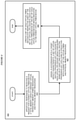
- FIG. 4 depicts a flowchart of an example process for affinity based optimization of virtual persistent memory volumes in accordance with an illustrative embodiment.
- hypervisor 301 apportions, responsive to receiving a request for a parent virtual PMEM device, a total memory capacity amongst virtual persistent memory (PMEM) resources and physical memory resources.
- the apportioning comprises a ratio of the virtual persistent memory (PMEM) to the physical memory resources.
- the user when configuring a virtual PMEM device for a guest 310 , the user follows workload specific guidelines to create a single parent virtual PMEM device of the appropriate capacity. Each parent virtual PMEM device will be assigned a unique identifier (GUID). The GUID will be used by the user during configuration of a workload within the guest to identify the virtual PMEM device provisioned for the workload.
- GUID unique identifier
- hypervisor 301 assigns, in accordance with a target affinity characteristic, a set of virtual central processor unit (CPU) sockets.
- Each virtual CPU socket is configured based on at least one physical central processor unit (CPU) core in conjunction with a subset of the virtual PMEM and physical memory resources.
- the affinity characteristic indicates an access proximity of physical memory to physical CPU cores for a particular virtual CPU socket of the set of virtual CPU sockets.
- the affinity characteristic is measurable as a ratio of the physical memory to the physical CPU cores that are assigned to the particular virtual CPU socket.
- the hypervisor will determine the total DRAM requirement for both regular DRAM (or physical DRAM as referred to herein) and virtual PMEM device assignments for the guest. The hypervisor will also determine the ratio of DRAM required for virtual PMEM devices and the physical DRAM assignment. An affinity optimization algorithm will determine how to optimally assign physical CPU core and DRAM capacity to the guest based on the total DRAM requirements.
- hypervisor 301 creates a set of child virtual PMEM devices for respective ones of the set of virtual CPU sockets.
- Each child virtual PMEM device of the set of child virtual PMEM devices is dedicated to the parent virtual PMEM device.
- the hypervisor will create a child virtual PMEM device for each parent virtual PMEM device for each CPU socket with DRAM and CPU cores assigned to the guest.
- the size of each child virtual PMEM device will be based on the ratio of DRAM required for the parent virtual PMEM devices and the physical DRAM assignment.
- the guest would receive 50 GB of physical DRAM and a 50 GB child virtual PMEM device on one CPU socket and 75 GB of physical DRAM and a 75 GB child virtual PMEM device on each of the other two CPU sockets.
- FIG. 5 depicts a flowchart of an example process for affinity based optimization of virtual persistent memory volumes.
- Process 500 can be implemented using hypervisor 301 in FIG. 3 , in conjunction with process 400 as depicted in FIG. 400 .
- the hypervisor 301 assigns a respective identifier (ID) to each of the child virtual PMEM devices.
- ID a respective identifier
- Each of the child virtual PMEM devices will be assigned a child GUID.
- the child GUID will be presented to the operating system and used for unique identification of the child virtual PMEM devices for determination of the contained data, proper filesystem mount point, etc.
- hypervisor 301 associates the ID of each of the child virtual PMEM devices with the parent virtual PMEM device.
- Each child virtual PMEM device presented to the operating system will also contain the parent GUID for the associated parent virtual PMEM device.
- FIG. 6 depicts a flowchart of an example process for affinity based optimization of virtual persistent memory volumes in accordance with another illustrative embodiment.
- Process 600 can be implemented in hypervisor 301 in FIG. 3 , in conjunction with process 400 as depicted in FIG. 4 .
- hypervisor 301 communicates the ID of each of the child virtual PMEM devices to an operating system.
- Each of the child virtual PMEM devices will be assigned a child GUID.
- the child GUID will be presented to the operating system and used for unique identification of the child virtual PMEM devices for determination of the contained data, proper filesystem mount point, etc.
- Each child virtual PMEM device presented to the operating system will also contain the parent GUID for the associated parent virtual PMEM device.
- hypervisor 301 provisions the parent virtual PMEM device for use by a workload.
- the workload When the workload is started, it will examine the devices presented to the operating system to identify the set of child virtual PMEM devices containing the parent GUID of the parent virtual PMEM device provisioned for the workload by the user. The workload will then initialize each of the discovered devices properly based on how it intends to exploit persistent memory.
- the workload may create a filesystem on each child device and mount it at a location in the overall filesystem that indicates its association with a set of CPU cores.
- the workload may instead record in its own data structures the address space of the devices and their associated CPU sockets
- FIG. 7 depicts a flowchart of an example process for affinity based optimization of virtual persistent memory volumes in accordance with an additional illustrative embodiment.
- Process 700 can be implemented in hypervisor 301 of FIG. 3 , in conjunction with process 400 as depicted in FIG. 4 .
- hypervisor 301 assigns a unique identifier (GUID) to the parent virtual PMEM device.
- GUID is used during configuration of a workload to identify the parent virtual PMEM device as provisioned for the workload.
- Each of the child virtual PMEM devices are assigned a child GUID.
- the child GUID will be presented to the operating system and used for unique identification of the child virtual PMEM devices for determination of the contained data, proper filesystem mount point, etc.
- Each child virtual PMEM device presented to the operating system will also contain the parent GUID for the associated parent virtual PMEM device.
- a computer implemented method, system or apparatus, and computer program product are provided in the illustrative embodiments for affinity based optimization of virtual PMEM placements and other related features, functions, or operations. Where an embodiment or a portion thereof is described with respect to a type of device, the computer implemented method, system or apparatus, the computer program product, or a portion thereof, are adapted or configured for use with a suitable and comparable manifestation of that type of device.
- SaaS Software as a Service
- a SaaS model the capability of the application implementing an embodiment is provided to a user by executing the application in a cloud infrastructure.
- the user can access the application using a variety of client devices through a thin client interface such as a web browser (e.g., web-based e-mail), or other light-weight client-applications.
- the user does not manage or control the underlying cloud infrastructure including the network, servers, operating systems, or the storage of the cloud infrastructure.
- the user may not even manage or control the capabilities of the SaaS application.
- the SaaS implementation of the application may permit a possible exception of limited user-specific application configuration settings.
- the present invention may be a system, a method, and/or a computer program product at any possible technical detail level of integration
- the computer program product may include a computer readable storage medium (or media) having computer readable program instructions thereon for causing a processor to carry out aspects of the present invention
- the computer readable storage medium can be a tangible device that can retain and store instructions for use by an instruction execution device.
- the computer readable storage medium may be, for example, but is not limited to, an electronic storage device, a magnetic storage device, an optical storage device, an electromagnetic storage device, a semiconductor storage device, or any suitable combination of the foregoing.
- a non-exhaustive list of more specific examples of the computer readable storage medium includes the following: a portable computer diskette, a hard disk, a random access memory (RAM), a read-only memory (ROM), an erasable programmable read-only memory (EPROM or Flash memory), a static random access memory (SRAM), a portable compact disc read-only memory (CD-ROM), a digital versatile disk (DVD), a memory stick, a floppy disk, a mechanically encoded device such as punch-cards or raised structures in a groove having instructions recorded thereon, and any suitable combination of the foregoing.
- RAM random access memory
- ROM read-only memory
- EPROM or Flash memory erasable programmable read-only memory
- SRAM static random access memory
- CD-ROM compact disc read-only memory
- DVD digital versatile disk
- memory stick a floppy disk
- a mechanically encoded device such as punch-cards or raised structures in a groove having instructions recorded thereon
- a computer readable storage medium is not to be construed as being transitory signals per se, such as radio waves or other freely propagating electromagnetic waves, electromagnetic waves propagating through a waveguide or other transmission media (e.g., light pulses passing through a fiber-optic cable), or electrical signals transmitted through a wire.
- Computer readable program instructions described herein can be downloaded to respective computing/processing devices from a computer readable storage medium or to an external computer or external storage device via a network, for example, the Internet, a local area network, a wide area network and/or a wireless network.
- the network may comprise copper transmission cables, optical transmission fibers, wireless transmission, routers, firewalls, switches, gateway computers and/or edge servers.
- a network adapter card or network interface in each computing/processing device receives computer readable program instructions from the network and forwards the computer readable program instructions for storage in a computer readable storage medium within the respective computing/processing device.
- Computer readable program instructions for carrying out operations of the present invention may be assembler instructions, instruction-set-architecture (ISA) instructions, machine instructions, machine dependent instructions, microcode, firmware instructions, state-setting data, configuration data for integrated circuitry, or either source code or object code written in any combination of one or more programming languages, including an object oriented programming language such as Smalltalk, C++, or the like, and procedural programming languages, such as the “C” programming language or similar programming languages.
- the computer readable program instructions may execute entirely on the user's computer, partly on the user's computer, as a stand-alone software package, partly on the user's computer and partly on a remote computer or entirely on the remote computer or server.
- the remote computer may be connected to the user's computer through any type of network, including a local area network (LAN) or a wide area network (WAN), or the connection may be made to an external computer (for example, through the Internet using an Internet Service Provider).
- electronic circuitry including, for example, programmable logic circuitry, field-programmable gate arrays (FPGA), or programmable logic arrays (PLA) may execute the computer readable program instructions by utilizing state information of the computer readable program instructions to personalize the electronic circuitry, in order to perform aspects of the present invention.
- These computer readable program instructions may be provided to a processor of a general purpose computer, special purpose computer, or other programmable data processing apparatus to produce a machine, such that the instructions, which execute via the processor of the computer or other programmable data processing apparatus, create means for implementing the functions/acts specified in the flowchart and/or block diagram block or blocks.
- These computer readable program instructions may also be stored in a computer readable storage medium that can direct a computer, a programmable data processing apparatus, and/or other devices to function in a particular manner, such that the computer readable storage medium having instructions stored therein comprises an article of manufacture including instructions which implement aspects of the function/act specified in the flowchart and/or block diagram block or blocks.
- the computer readable program instructions may also be loaded onto a computer, other programmable data processing apparatus, or other device to cause a series of operational steps to be performed on the computer, other programmable apparatus or other device to produce a computer implemented process, such that the instructions which execute on the computer, other programmable apparatus, or other device implement the functions/acts specified in the flowchart and/or block diagram block or blocks.
- each block in the flowchart or block diagrams may represent a module, segment, or portion of instructions, which comprises one or more executable instructions for implementing the specified logical function(s).
- the functions noted in the blocks may occur out of the order noted in the Figures.
- two blocks shown in succession may, in fact, be executed substantially concurrently, or the blocks may sometimes be executed in the reverse order, depending upon the functionality involved.
Landscapes
- Engineering & Computer Science (AREA)
- Theoretical Computer Science (AREA)
- Software Systems (AREA)
- Physics & Mathematics (AREA)
- General Engineering & Computer Science (AREA)
- General Physics & Mathematics (AREA)
- Data Mining & Analysis (AREA)
- Databases & Information Systems (AREA)
- Information Retrieval, Db Structures And Fs Structures Therefor (AREA)
Abstract
Description
Claims (20)
Priority Applications (1)
| Application Number | Priority Date | Filing Date | Title |
|---|---|---|---|
| US16/594,873 US11249804B2 (en) | 2019-10-07 | 2019-10-07 | Affinity based optimization of virtual persistent memory volumes |
Applications Claiming Priority (1)
| Application Number | Priority Date | Filing Date | Title |
|---|---|---|---|
| US16/594,873 US11249804B2 (en) | 2019-10-07 | 2019-10-07 | Affinity based optimization of virtual persistent memory volumes |
Publications (2)
| Publication Number | Publication Date |
|---|---|
| US20210103474A1 US20210103474A1 (en) | 2021-04-08 |
| US11249804B2 true US11249804B2 (en) | 2022-02-15 |
Family
ID=75274087
Family Applications (1)
| Application Number | Title | Priority Date | Filing Date |
|---|---|---|---|
| US16/594,873 Active 2040-03-03 US11249804B2 (en) | 2019-10-07 | 2019-10-07 | Affinity based optimization of virtual persistent memory volumes |
Country Status (1)
| Country | Link |
|---|---|
| US (1) | US11249804B2 (en) |
Families Citing this family (1)
| Publication number | Priority date | Publication date | Assignee | Title |
|---|---|---|---|---|
| CN113282525B (en) * | 2021-05-27 | 2023-03-28 | 杭州迪普科技股份有限公司 | Message distribution method and device |
Citations (11)
| Publication number | Priority date | Publication date | Assignee | Title |
|---|---|---|---|---|
| US20040139287A1 (en) * | 2003-01-09 | 2004-07-15 | International Business Machines Corporation | Method, system, and computer program product for creating and managing memory affinity in logically partitioned data processing systems |
| US20040148360A1 (en) | 2003-01-24 | 2004-07-29 | Hewlett-Packard Development Company | Communication-link-attached persistent memory device |
| EP1988473B1 (en) | 2007-05-04 | 2012-02-08 | Helge Hofmeister | A server with a core using a virtual file system and a method for securely redirecting a persistent storage device operation to a middleware infrastructure |
| US20120311274A1 (en) * | 2008-06-06 | 2012-12-06 | International Business Machines Corporation | Dynamic control of partition memory affinity in a shared memory partition data processing system |
| US8972991B2 (en) | 2004-12-21 | 2015-03-03 | Microsoft Technology Licensing, Llc | Systems and methods for exposing processor topology for virtual machines |
| US9213609B2 (en) | 2003-12-16 | 2015-12-15 | Hewlett-Packard Development Company, L.P. | Persistent memory device for backup process checkpoint states |
| US9792221B2 (en) | 2013-11-22 | 2017-10-17 | Swarm64 As | System and method for improving performance of read/write operations from a persistent memory device |
| US20170300442A1 (en) | 2015-11-17 | 2017-10-19 | Shanghai Jiao Tong University | Hot plug method and device for byte addressable persistent memory |
| US10037228B2 (en) | 2012-10-25 | 2018-07-31 | Nvidia Corporation | Efficient memory virtualization in multi-threaded processing units |
| US20190095114A1 (en) * | 2017-09-22 | 2019-03-28 | Dell Products L.P. | Systems and methods for dynamically modifying memory namespace allocation based on memory attributes and application requirements |
| US10754792B2 (en) * | 2016-01-29 | 2020-08-25 | Hewlett Packard Enterprise Development Lp | Persistent virtual address spaces |
-
2019
- 2019-10-07 US US16/594,873 patent/US11249804B2/en active Active
Patent Citations (12)
| Publication number | Priority date | Publication date | Assignee | Title |
|---|---|---|---|---|
| US20040139287A1 (en) * | 2003-01-09 | 2004-07-15 | International Business Machines Corporation | Method, system, and computer program product for creating and managing memory affinity in logically partitioned data processing systems |
| US20040148360A1 (en) | 2003-01-24 | 2004-07-29 | Hewlett-Packard Development Company | Communication-link-attached persistent memory device |
| US9213609B2 (en) | 2003-12-16 | 2015-12-15 | Hewlett-Packard Development Company, L.P. | Persistent memory device for backup process checkpoint states |
| US8972991B2 (en) | 2004-12-21 | 2015-03-03 | Microsoft Technology Licensing, Llc | Systems and methods for exposing processor topology for virtual machines |
| EP1988473B1 (en) | 2007-05-04 | 2012-02-08 | Helge Hofmeister | A server with a core using a virtual file system and a method for securely redirecting a persistent storage device operation to a middleware infrastructure |
| US20120311274A1 (en) * | 2008-06-06 | 2012-12-06 | International Business Machines Corporation | Dynamic control of partition memory affinity in a shared memory partition data processing system |
| US8688923B2 (en) | 2008-06-06 | 2014-04-01 | International Business Machines Corporation | Dynamic control of partition memory affinity in a shared memory partition data processing system |
| US10037228B2 (en) | 2012-10-25 | 2018-07-31 | Nvidia Corporation | Efficient memory virtualization in multi-threaded processing units |
| US9792221B2 (en) | 2013-11-22 | 2017-10-17 | Swarm64 As | System and method for improving performance of read/write operations from a persistent memory device |
| US20170300442A1 (en) | 2015-11-17 | 2017-10-19 | Shanghai Jiao Tong University | Hot plug method and device for byte addressable persistent memory |
| US10754792B2 (en) * | 2016-01-29 | 2020-08-25 | Hewlett Packard Enterprise Development Lp | Persistent virtual address spaces |
| US20190095114A1 (en) * | 2017-09-22 | 2019-03-28 | Dell Products L.P. | Systems and methods for dynamically modifying memory namespace allocation based on memory attributes and application requirements |
Non-Patent Citations (1)
| Title |
|---|
| Vasily A. Sartakov, NV-Hypervisor: Hypervisor-based Persistence for Virtual Machines; 2014 IEEE (Year: 2014). * |
Also Published As
| Publication number | Publication date |
|---|---|
| US20210103474A1 (en) | 2021-04-08 |
Similar Documents
| Publication | Publication Date | Title |
|---|---|---|
| US10324754B2 (en) | Managing virtual machine patterns | |
| US10514960B2 (en) | Iterative rebalancing of virtual resources among VMs to allocate a second resource capacity by migrating to servers based on resource allocations and priorities of VMs | |
| US10176004B2 (en) | Workload-aware load balancing to minimize scheduled downtime during maintenance of host or hypervisor of a virtualized computing system | |
| US9928112B2 (en) | Configuration of floating node boundaries | |
| US10552217B2 (en) | Workload placement in a hybrid cloud environment | |
| US11948010B2 (en) | Tag-driven scheduling of computing resources for function execution | |
| JP2021513137A (en) | Data migration in a tiered storage management system | |
| US11983561B2 (en) | Configuring hardware multithreading in containers | |
| US20150154048A1 (en) | Managing workload to provide more uniform wear among components within a computer cluster | |
| US11249804B2 (en) | Affinity based optimization of virtual persistent memory volumes | |
| US10228982B2 (en) | Hyper-threaded processor allocation to nodes in multi-tenant distributed software systems | |
| US20230086195A1 (en) | Efficient and extensive function groups with multi-instance function support for cloud based processing | |
| JP7563857B2 (en) | Virtual Machine Migration Detected by the Host Operating System | |
| US12088627B2 (en) | Security and task performance validation for a cooperative device network | |
| JP7663299B2 (en) | Parallel Task Initialization on Dynamic Computing Resources | |
| US11960917B2 (en) | Live migration and redundancy for virtualized storage | |
| US11816363B2 (en) | File based virtual disk management | |
| US20230015103A1 (en) | Live updating a virtual machine virtualizing physical resources | |
| CN116719605A (en) | A GPU load deployment method, cloud computing platform, and electronic equipment |
Legal Events
| Date | Code | Title | Description |
|---|---|---|---|
| AS | Assignment |
Owner name: INTERNATIONAL BUSINESS MACHINES CORPORATION, NEW YORK Free format text: ASSIGNMENT OF ASSIGNORS INTEREST;ASSIGNORS:STANTON, DAVID ANTHONY LARSON;JACOBS, STUART ZACHARY;ARMSTRONG, TROY DAVID;AND OTHERS;SIGNING DATES FROM 20191004 TO 20191007;REEL/FRAME:050644/0185 |
|
| FEPP | Fee payment procedure |
Free format text: ENTITY STATUS SET TO UNDISCOUNTED (ORIGINAL EVENT CODE: BIG.); ENTITY STATUS OF PATENT OWNER: LARGE ENTITY |
|
| STPP | Information on status: patent application and granting procedure in general |
Free format text: NON FINAL ACTION MAILED |
|
| STPP | Information on status: patent application and granting procedure in general |
Free format text: RESPONSE TO NON-FINAL OFFICE ACTION ENTERED AND FORWARDED TO EXAMINER |
|
| STPP | Information on status: patent application and granting procedure in general |
Free format text: NOTICE OF ALLOWANCE MAILED -- APPLICATION RECEIVED IN OFFICE OF PUBLICATIONS |
|
| STPP | Information on status: patent application and granting procedure in general |
Free format text: DOCKETED NEW CASE - READY FOR EXAMINATION |
|
| STPP | Information on status: patent application and granting procedure in general |
Free format text: NOTICE OF ALLOWANCE MAILED -- APPLICATION RECEIVED IN OFFICE OF PUBLICATIONS |
|
| STPP | Information on status: patent application and granting procedure in general |
Free format text: PUBLICATIONS -- ISSUE FEE PAYMENT RECEIVED |
|
| STCF | Information on status: patent grant |
Free format text: PATENTED CASE |
|
| MAFP | Maintenance fee payment |
Free format text: PAYMENT OF MAINTENANCE FEE, 4TH YEAR, LARGE ENTITY (ORIGINAL EVENT CODE: M1551); ENTITY STATUS OF PATENT OWNER: LARGE ENTITY Year of fee payment: 4 |