US11248561B2 - Exhaust nozzle of a gas turbine engine - Google Patents
Exhaust nozzle of a gas turbine engine Download PDFInfo
- Publication number
- US11248561B2 US11248561B2 US16/719,112 US201916719112A US11248561B2 US 11248561 B2 US11248561 B2 US 11248561B2 US 201916719112 A US201916719112 A US 201916719112A US 11248561 B2 US11248561 B2 US 11248561B2
- Authority
- US
- United States
- Prior art keywords
- sliding element
- strut
- radial
- nozzle
- struts
- Prior art date
- Legal status (The legal status is an assumption and is not a legal conclusion. Google has not performed a legal analysis and makes no representation as to the accuracy of the status listed.)
- Active, expires
Links
Images


Classifications
-
- F—MECHANICAL ENGINEERING; LIGHTING; HEATING; WEAPONS; BLASTING
- F02—COMBUSTION ENGINES; HOT-GAS OR COMBUSTION-PRODUCT ENGINE PLANTS
- F02K—JET-PROPULSION PLANTS
- F02K1/00—Plants characterised by the form or arrangement of the jet pipe or nozzle; Jet pipes or nozzles peculiar thereto
- F02K1/04—Mounting of an exhaust cone in the jet pipe
-
- F—MECHANICAL ENGINEERING; LIGHTING; HEATING; WEAPONS; BLASTING
- F02—COMBUSTION ENGINES; HOT-GAS OR COMBUSTION-PRODUCT ENGINE PLANTS
- F02K—JET-PROPULSION PLANTS
- F02K1/00—Plants characterised by the form or arrangement of the jet pipe or nozzle; Jet pipes or nozzles peculiar thereto
- F02K1/06—Varying effective area of jet pipe or nozzle
- F02K1/08—Varying effective area of jet pipe or nozzle by axially moving or transversely deforming an internal member, e.g. the exhaust cone
-
- F—MECHANICAL ENGINEERING; LIGHTING; HEATING; WEAPONS; BLASTING
- F02—COMBUSTION ENGINES; HOT-GAS OR COMBUSTION-PRODUCT ENGINE PLANTS
- F02K—JET-PROPULSION PLANTS
- F02K1/00—Plants characterised by the form or arrangement of the jet pipe or nozzle; Jet pipes or nozzles peculiar thereto
- F02K1/78—Other construction of jet pipes
- F02K1/82—Jet pipe walls, e.g. liners
-
- F—MECHANICAL ENGINEERING; LIGHTING; HEATING; WEAPONS; BLASTING
- F05—INDEXING SCHEMES RELATING TO ENGINES OR PUMPS IN VARIOUS SUBCLASSES OF CLASSES F01-F04
- F05D—INDEXING SCHEME FOR ASPECTS RELATING TO NON-POSITIVE-DISPLACEMENT MACHINES OR ENGINES, GAS-TURBINES OR JET-PROPULSION PLANTS
- F05D2220/00—Application
- F05D2220/30—Application in turbines
- F05D2220/32—Application in turbines in gas turbines
- F05D2220/323—Application in turbines in gas turbines for aircraft propulsion, e.g. jet engines
-
- F—MECHANICAL ENGINEERING; LIGHTING; HEATING; WEAPONS; BLASTING
- F05—INDEXING SCHEMES RELATING TO ENGINES OR PUMPS IN VARIOUS SUBCLASSES OF CLASSES F01-F04
- F05D—INDEXING SCHEME FOR ASPECTS RELATING TO NON-POSITIVE-DISPLACEMENT MACHINES OR ENGINES, GAS-TURBINES OR JET-PROPULSION PLANTS
- F05D2240/00—Components
- F05D2240/10—Stators
- F05D2240/12—Fluid guiding means, e.g. vanes
- F05D2240/128—Nozzles
-
- F—MECHANICAL ENGINEERING; LIGHTING; HEATING; WEAPONS; BLASTING
- F05—INDEXING SCHEMES RELATING TO ENGINES OR PUMPS IN VARIOUS SUBCLASSES OF CLASSES F01-F04
- F05D—INDEXING SCHEME FOR ASPECTS RELATING TO NON-POSITIVE-DISPLACEMENT MACHINES OR ENGINES, GAS-TURBINES OR JET-PROPULSION PLANTS
- F05D2240/00—Components
- F05D2240/90—Mounting on supporting structures or systems
- F05D2240/91—Mounting on supporting structures or systems on a stationary structure
-
- F—MECHANICAL ENGINEERING; LIGHTING; HEATING; WEAPONS; BLASTING
- F05—INDEXING SCHEMES RELATING TO ENGINES OR PUMPS IN VARIOUS SUBCLASSES OF CLASSES F01-F04
- F05D—INDEXING SCHEME FOR ASPECTS RELATING TO NON-POSITIVE-DISPLACEMENT MACHINES OR ENGINES, GAS-TURBINES OR JET-PROPULSION PLANTS
- F05D2250/00—Geometry
- F05D2250/40—Movement of components
- F05D2250/41—Movement of components with one degree of freedom
-
- F—MECHANICAL ENGINEERING; LIGHTING; HEATING; WEAPONS; BLASTING
- F05—INDEXING SCHEMES RELATING TO ENGINES OR PUMPS IN VARIOUS SUBCLASSES OF CLASSES F01-F04
- F05D—INDEXING SCHEME FOR ASPECTS RELATING TO NON-POSITIVE-DISPLACEMENT MACHINES OR ENGINES, GAS-TURBINES OR JET-PROPULSION PLANTS
- F05D2260/00—Function
- F05D2260/94—Functionality given by mechanical stress related aspects such as low cycle fatigue [LCF] of high cycle fatigue [HCF]
- F05D2260/941—Functionality given by mechanical stress related aspects such as low cycle fatigue [LCF] of high cycle fatigue [HCF] particularly aimed at mechanical or thermal stress reduction
Definitions
- the present disclosure relates to an exhaust nozzle of a gas turbine engine.
- the centerbody and the struts are exposed both to the hot core airflow from the primary channel that has passed the core engine and to the colder bypass airflow from the bypass channel, whereas the outer nozzle wall is exposed mostly to the colder bypass airflow. This leads to a different thermal expansion of these components and, accordingly, to thermal stresses acting on these components.
- an exhaust nozzle for a gas turbine engine comprising an outer nozzle wall, a flow channel which is limited radially outwards by the nozzle wall, a centerbody arranged in the flow channel, and at least two struts connecting the centerbody to the nozzle wall.
- a first strut is connected to the nozzle wall by a first connection, the first connection constraining movement of the strut relative to the nozzle wall in the radial direction and in the circumferential direction but allowing movement of the strut relative to the nozzle wall in the axial direction.
- a first actuator interacts with the first strut for displacing the first strut in the axial direction.
- the at least one other strut is connected to the nozzle wall by a second connection, the second connection constraining movement of the strut relative to the nozzle wall in the circumferential direction only but allowing movement of the strut relative to the nozzle wall in the radial and axial directions.
- At least one second actuator is provided, each second actuator interacting with one of the at least one other struts for displacing the respective strut in the axial direction.
- the second connection is formed by a second sliding element extending radially from the radial outer end of the strut and a second receiving slot extending in the axial direction in the nozzle wall, wherein the second sliding element is at least partly arranged in the second receiving slot, the second sliding element comprises an interaction zone in which it interacts with the second actuator for axial movement of the strut, and wherein the interaction zone has a radial length such that the interaction between the second actuator and the interaction zone is maintained when the second sliding element is moved in the radial direction by radial thermal expansion of the strut and/or the centerpiece.
- aspects of the invention are thus based on the idea to allow for a sliding movement of at least one of the struts relative to the nozzle wall in the radial direction, such radial movement allowing to compensate for a different thermal expansion of the struts and centerbody compared to the thermal expansion of the nozzle wall.
- an interaction zone in which an actuator interacts with a sliding element of the radially displaceable strut, wherein the interaction zone is of sufficient radial length to ensure that when the sliding element is moved in the radial direction the interaction between the actuator and the interaction zone is maintained.
- the second sliding element is formed as a flat element having a surface that extends in the axial direction, wherein the interconnection zone for interacting with the second actuator is formed by a toothing in the surface of the flat second sliding element.
- the toothing may be formed as a toothed rack.
- the toothed rack comprises teeth formed substantially in the radial direction, whilst the main direction of the whole rack is axial.
- the second actuator may comprise a worm screw that interacts with the toothing formed on the surface of the second sliding element.
- the second actuator and the toothing of the second sliding element form a worm and rack drive.
- the interaction zone has a radial length that is at least equal to the maximum radial expansion that the struts and the centerbody experience between a cold condition and maximum temperatures reached during operation.
- the second sliding element is form-fitted only in the circumferential direction to the second receiving slot. Accordingly, the second sliding element is formed and arranged such in the second receiving slot that it cannot be displaced in the circumferential directions but can be displaced in the radial and axial directions.
- the second receiving slot may be formed as a slot with rectangular cross-section.
- the second receiving slot has a radial length that is larger than the maximum radial expansion of the struts and of the centerbody between a cold condition and temperatures reached during operation of the gas turbine engine. Thereby, radial expansion of the struts and of the centerbody can take place without thermal stresses acting between the nozzle wall and the struts.
- the first connection is formed by a first sliding element and a first receiving slot, wherein the first sliding element extends radially from the radial outer end of the strut. It further extends in the axial direction, thereby forming an elongated lip or rail.
- the first receiving slot extends in the axial direction in the nozzle wall such that the first sliding element and the first receiving slot allow to displace the strut relative to the nozzle wall in the axial direction.
- the first sliding element is form-fitted in the radial and circumferential directions to the first receiving slot. Accordingly, the first sliding element is formed and arranged such in the first receiving slot that it cannot be displaced in the radial and circumferential directions.
- the first actuator interacts with the first sliding element to cause axial movement of the first sliding element and respective strut.
- the first sliding element and the first receiving slot may comprise, in cross section, corresponding keyhole shapes that provide for the form-fit in the radial and circumferential directions (wherein the cross-section of the keyhole shape of the sliding element is smaller than the cross-section of the keyhole shape of first receiving slot).
- the first sliding element and the first receiving slot may both comprise a circular cross-section.
- the first sliding element and the first receiving slot may form a dovetail-connection.
- the first sliding element comprises a toothing, wherein the first actuator interacts with the toothing.
- the toothing forms a toothed rack.
- the toothed rack may comprise teeth which run substantially in the circumferential direction.
- the first actuator may be formed by a worm screw that interacts with the toothing of the first sliding element.
- the first actuator and the toothing of the first sliding element may form a worm and rack drive.
- the first sliding element may comprise a radial outer section.
- the toothing may be formed in the radial outer section of the first sliding element.
- the radial outer section of the first sliding element is formed as a cylinder, wherein the toothing is formed in the radial outer side of the cylinder.
- the nozzle comprises exactly two struts, one strut being connected to the nozzle wall by the first connection and the other strut being connected to the nozzle wall by the second connection.
- the two struts may be arranged approximately in a plane. In such case, such plane defines a lateral direction, wherein the radial direction is identical to the lateral direction.
- the first connection may be realized in an inboard area of the nozzle located adjacent an aircraft fuselage that carries the gas turbine engine which implements the exhaust nozzle and the second connection may be realized at an outboard area of the nozzle located remote to the aircraft fuselage.
- the exhaust nozzle may be a convergent-divergent nozzle, wherein the cross-section of the nozzle first decreases in the downstream direction towards a nozzle throat area (usually referred to as A 8 ) and subsequently increases until it reaches the nozzle exit area (usually referred to as A 9 ).
- a 8 nozzle throat area
- a 9 nozzle exit area
- the nozzle is configured as the nozzle of a supersonic gas turbine engine which is designed for operating conditions in the subsonic, transonic and supersonic ranges.
- an exhaust nozzle for a gas turbine engine which comprises: an outer nozzle wall, a flow channel which is limited radially outwards by the nozzle wall, a centerbody arranged in the flow channel, and at least two struts connecting the centerbody to the nozzle wall.
- the struts are each connected to the nozzle wall by a connection that constrains movement of the strut relative to the nozzle wall in the circumferential direction but allows movement of the strut relative to the nozzle wall in the radial and axial directions.
- actuators are provided, wherein each actuator is associated with a strut for displacing the strut in the axial direction.
- connection is formed in each case by a sliding element extending radially from the radial outer end of the strut and a receiving slot extending in the axial direction in the nozzle wall, wherein the sliding element is at least partly arranged in the receiving slot, the sliding element comprises an interaction zone in which it interacts with the actuator for axial movement of the strut, and wherein the interaction zone has a radial length such that the interaction between the actuator and the interaction zone is maintained when the sliding element is moved in the radial direction by radial thermal expansion of the strut and/or the centerpiece.
- This aspect of the invention is based on the idea to allow for a sliding movement of all struts relative to the nozzle wall in the radial direction, such radial movement allowing to compensate for a different thermal expansion of the struts and centerbody compared to the thermal expansion of the nozzle wall.
- an interaction zone in which an actuator interacts with a sliding element of the radially displaceable strut, wherein the interaction zone is of sufficient radial length to ensure that when the sliding element is moved in the radial direction the interaction between the actuator and the interaction zone is maintained.
- the movement when referring to a movement in the axial direction, the movement can be both in the axial direction and against the axial direction, i.e., back and forth.
- x indicates the axial direction
- r the radial direction
- ⁇ the angle in the circumferential direction.
- the axial direction is defined by the machine axis/engine centerline of the gas turbine engine, with the axial direction pointing from the engine inlet to the engine outlet.
- the axial direction of the gas turbine engine is at least substantially identical with the axial direction of the exhaust nozzle of the gas turbine engine. Starting from the x-axis, the radial direction points radially outwards. Terms such as “in front of” and “behind” refer to the axial direction or flow direction in the engine. Terms such as “outer” or “inner” refer to the radial direction.
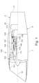
- FIG. 1 is a schematic sectional side view of a supersonic gas turbine engine
- FIG. 2 is a sectional view of an example of an exhaust nozzle that comprises a centerbody that is connected via two struts to an outer nozzle wall;
- FIG. 3 is a partly sectional front view of an embodiment of an exhaust nozzle that comprises a centerbody that is connected via two struts to an outer nozzle wall, wherein different connections are implemented to connect the struts with the outer nozzle wall;
- FIG. 4 a schematic front view of an exhaust nozzle in accordance with FIG. 3 , wherein the acting forces are schematically indicated;
- FIG. 5 shows an embodiment of a drive connection between an actuator that comprises a worm screw and a toothed rack that is formed in a sliding element of a strut, wherein the worm and rack connection is integrated into a first connection that constrains a relative movement between the strut and the outer nozzle in the radial direction;
- FIG. 6 is an enlarged top view of the worm screw and the toothed rack of the embodiment of FIG. 5 ;
- FIG. 7 is a rear view of the worm screw and the toothed rack of the embodiment of FIG. 5 :
- FIG. 8 shows an embodiment of a drive connection between an actuator that comprises a worm screw and a toothed rack that is formed in a flat sliding element of a strut, wherein the warm and rack connection is integrated into a second connection that enables a relative movement between the strut and the outer nozzle in the radial direction, wherein the toothed rack is formed in the surface of the flat sliding element;
- FIG. 9 the arrangement of the flat sliding element of FIG. 8 in a receiving slot of the outer nozzle wall with a first radial extension of the sliding element which is present in a cold condition
- FIG. 10 the arrangement of the flat sliding element of FIG. 8 in a receiving slot of the outer nozzle wall with a second radial extension of the sliding element which is present in a hot condition.
- FIG. 1 shows a turbofan engine which is intended and suitable for use in a civil or military supersonic aircraft and, accordingly, is designed for operating conditions in the subsonic, transonic and supersonic ranges.
- the principles of this invention can also be implemented in a turbofan engine designed for subsonic operation only. The description of the invention in the context of an engine intended for a supersonic aircraft is therefore only to be understood as an example.
- the turbofan engine 100 comprises an engine intake 101 , a fan 102 which may be a multi-stage fan, a primary flow channel 103 which passes through a core engine, a secondary flow channel 104 which bypasses the core engine, a mixer 105 and a nozzle 2 in which a thrust reverser 8 can be integrated.
- the turbofan engine 100 has a machine axis or engine centerline 10 .
- the machine axis 10 defines an axial direction of the turbofan engine.
- a radial direction of the turbofan engine is perpendicular to the axial direction.
- the core engine comprises a compressor 106 , a combustion chamber 107 and a turbine 108 , 109 .
- the compressor comprises a high-pressure compressor 106 .
- a low-pressure compressor is formed by the areas close to the hub of the fan 102 .
- the turbine behind the combustion chamber 107 comprises a high-pressure turbine 108 and a low-pressure turbine 109 .
- the high-pressure turbine 108 drives a high-pressure shaft 110 which connects the high-pressure turbine 108 with the high-pressure compressor 106 .
- the low-pressure turbine 109 drives a low-pressure shaft 111 which connects the low-pressure turbine 109 with the multi-stage fan 102 .
- the turbofan engine may also have a medium-pressure compressor, a medium-pressure turbine and a medium-pressure shaft. Furthermore, in an alternative design it can be provided that the fan 102 is coupled to the low-pressure shaft 111 via a reduction gearbox, e.g., a planetary gearbox.
- a reduction gearbox e.g., a planetary gearbox.
- the turbofan engine is arranged in an engine nacelle 1 .
- the engine nacelle 1 may be connected to the aircraft fuselage via a pylon.
- the engine inlet is beveled in FIG. 1 , with the lower edge protruding from the upper edge, but other kinds of supersonic intakes may be implemented instead.
- the flow channel through the fan 102 is divided behind the fan 102 into the primary flow channel 103 and the secondary flow channel 104 .
- the secondary flow channel 104 is also referred to as the bypass channel.
- the primary flow in the primary flow channel 103 and the secondary flow in the secondary flow channel 104 are mixed by the mixer 105 . Furthermore, an outlet cone 113 is mounted behind the turbine in order to achieve desired cross-sections of the flow channel.
- the rear area of the turbofan engine is formed by an integral nozzle 2 , where the primary and secondary flows are mixed in the mixer 105 before being fed into the integral nozzle 2 .
- the engine behind mixer 105 forms a flow channel 25 , which extends through nozzle 2 .
- separate nozzles can be provided for the primary flow channel 103 and the secondary flow channel 104 meaning that the flow through the secondary flow channel 104 has its own nozzle that is separate to and radially outside the core engine nozzle.
- One or both nozzles may have a fixed or variable area.
- FIG. 2 shows schematically the basic design of the nozzle 2 in a sectional view that contains the engine centerline 10 .
- Nozzle 2 comprises an outer nozzle wall 20 formed by an inner wall 21 and an outer wall 22 .
- the inner wall 21 forms the radially outer boundary of a flow channel 25 through the nozzle 2 .
- the outer wall 22 is formed radially outside to the inner wall 21 and adjoins the surroundings.
- the inner wall 21 and the outer wall 22 may converge at a point downstream to form a nozzle exit edge 23 at their downstream end.
- the nozzle 2 also includes a centerbody 5 , which forms a surface 55 .
- the centerbody 5 has a longitudinal axis identical to the engine centerline 10 .
- the centerbody 5 forms an upstream end 51 , a downstream end 52 and a maximum 53 of its cross-sectional area between the upstream end 51 and the downstream end 52 .
- the centerbody 5 is conical adjacent to its upstream end 51 and towards its downstream end 52 .
- the nozzle 2 forms a nozzle throat area A 8 where the cross-sectional area between centerbody 5 and inner wall 21 is minimum.
- the axial position of the nozzle throat area A 8 is defined by the axial position of the maximum 53 of the centerbody 5 .
- the thrust nozzle forms a nozzle exit area A 9 .
- This area is equal to the difference between the cross-sectional area formed by the inner wall 21 at the nozzle exit edge 23 and the cross-sectional area of the centerbody 5 in the plane under consideration.
- the ratio A 9 to A 8 defines the degree of expansion of the flow channel 25 behind the nozzle throat area A 8 .
- the nozzle 2 further comprises two struts 31 , 32 connecting the centerbody 5 to the nozzle wall 20 , namely, the inner wall 21 . They extend from the centerbody 5 in a radial direction through the flow channel 25 to the nozzle wall 20 .
- the struts 31 , 32 each have a profile with a front edge 311 , 321 and a rear edge 312 , 322 , as well as an upper side and a lower side.
- Each strut 31 , 32 has a radially outer end 313 , 323 at which it is connected to the inner wall 21 and a radially inner end 314 , 324 at which it is connected to the centerbody 5 .
- the struts 31 , 32 which may also be referred to as wings, are approximately arranged in a plane containing the engine centerline 10 .
- An arrangement of the struts “approximately” in a plane exists insofar as the struts have a three-dimensional extension corresponding to the profile they form.
- the two struts 31 , 32 are arranged at an angle to each other.
- the centerbody 5 is fixed to the struts 31 , 32 .
- the struts 31 , 32 can be displaced relative to the outer nozzle wall 20 , as will be discussed with respect to FIGS. 5-10 .
- the centerbody 5 may be a modulated centerbody, the cross-section of which varies along the axial direction, wherein the cross-section may have one or several maxima.
- FIGS. 3-10 discuss embodiments in which the struts 31 , 32 are connected to the outer nozzle wall 20 in a manner that allows to compensate for thermal expansion of the centerbody 5 and struts 31 , 32 .
- FIG. 3 shows in front view a centerbody 5 , which is connected by means of two struts 31 , 32 to an outer nozzle wall 20 which comprises an inner wall 21 and an outer wall 22 , similar to the example discussed with respect to FIG. 2 .
- the struts 31 , 32 have respective front edges 311 , 321 .
- the nozzle wall 20 has a circular cross-section.
- the centerbody 5 is located at the centerline of the nozzle 2 , which is identical to the centerline of the gas turbine engine.
- a flow channel 25 through the nozzle to is limited radially outwards by the nozzle wall 20 , namely, its inner wall 21 .
- the struts 31 , 32 are connected by means of different connections 4 , 6 to the nozzle wall 20 . More particularly, strut 31 is connected to nozzle wall 20 by means of a first connection 4 .
- the first connection 4 is formed by a first sliding element 40 and a first receiving slot 45 which both extend in the axial direction, wherein the first receiving slot 45 extends axially in the nozzle wall 20 .
- the first sliding element 40 extends radially from the radially outer end 313 of the strut 31 in the height of the front edge 311 and is located in a form-fit manner in the first receiving slot 45 .
- Such form-fit connection constrains movement of the first sliding element 40 and thus of the strut 31 both in the radial direction and in the circumferential direction. However, a relative movement in the axial direction is enabled.
- first sliding element 40 and of the first receiving slot 45 shown in FIG. 3 are to be understand as an example only. Other corresponding forms which allow for an axial movement while hindering a radial and circumferential movement may be implemented instead.
- first sliding element 40 and the first receiving slot 45 may comprise corresponding key-hole sliding profiles.
- the other strut 32 is connected to nozzle wall 20 by means of a second connection 6 .
- the second connection 6 is formed by a second sliding element 60 and a second receiving slot 65 which both extend in the axial direction, wherein the second receiving slot 60 extends axially in the nozzle wall 20 .
- the second sliding element 60 extend radially from the radially outer end 323 of strut 32 . It is formed as a blade, having a rectangular cross-section.
- the second receiving slot 65 is formed as a blade slot, having also a rectangular cross-section.
- the second sliding element 60 can move in and against the radial direction within the second receiving slot 65 . Accordingly, while one strut 31 is constrained in the radial direction, the other strut 32 does not experience any radial constraint and is free to expand in the radial direction, thereby avoiding the buildup of thermal stresses between the struts 31 , 32 and the nozzle wall 20 .
- the radial length of the receiving slot 65 is designed such that sufficient radial expansion ⁇ r of the struts 31 , 32 and of the centerbody 5 is possible.
- the struts have been sized and designed in cold condition such that, when heated up by hot airflow during operation, the struts expand to the ideal annulus lines under steady-state temperatures.
- the ideal annulus line is such that the radial outer ends 313 , 323 of struts 31 , 32 rest adjacent the inner wall 21 of the nozzle wall 20 , without exercising a stress on the nozzle wall.
- the blade 60 which represents the second sliding element is moved to a maximum ⁇ r in the radial direction into the blade slot 65 .
- the design of the struts is such that a natural thermal growth in hot conditions is enabled without transmitting excessive thermally induced loads.
- the length of the blade slot 65 depends on the coefficient of thermal expansion of the material used for the struts and for the centerbody.
- the radial expansion ⁇ r from the cold state condition to a high steady-state temperatures may be in the range between 5 mm and 10 mm. Accordingly, in embodiments, the radial length of the receiving slot may be in the range between 8 and 20 mm.
- the two struts 31 , 32 may be arranged approximately in a plane, such that the two connections 4 , 6 are approximately located at opposite sides of the nozzle wall. If the gas turbine engine which comprises the nozzle is attached to the fuselage of an airplane, it may be provided that the first connection 4 is located at the inboard side and that the second connection 6 is located at the outboard side of the nozzle.
- FIG. 4 shows in a schematic manner the two different connections 4 , 6 of the first strut 31 and the second strut 32 .
- the depiction is similar to that of FIG. 3 , wherein the connections 4 , 6 have been exaggerated, and wherein radial forces F r and circumferential forces F ⁇ that may apply are shown.
- the first connection 4 constraints both the radial forces F r and circumferential forces F ⁇ .
- the second connection 6 restraints only the circumferential forces F ⁇ , but allows movement of the blade 60 in the blade slot 65 in the radial direction in response to a radial force F r caused by thermal expansion, wherein a maximum radial displacement ⁇ r can be realized within the blade slot 65 , the amount of which depends on the properties of the used materials and the temperature difference.
- FIGS. 3 and 4 referred to embodiments that allow movement of at least one strut relative to the nozzle wall in the radial direction.
- FIGS. 5 to 10 discuss embodiments of how to displace the struts 31 , 32 back and forth in the axial direction.
- the implementation of a driving force to displace the struts 31 , 32 is carried out differently at the first connection 4 regarding strut 31 and the second connection 6 regarding strut 32 .
- FIGS. 5 to 7 show the provision of a driving force at the first connection 4 .
- a driving force is applied by an actuator 7 to a toothing 43 that is integrated into the first sliding element 40 of the first connection 4 .
- the first sliding element 40 is an elongated element extending in the axial direction. It comprises a bridge 41 directly connected to the radially outer end 313 of strut 31 and a cylindrical element 42 , the form of which corresponds to the form of the first receiving slot (not shown in FIGS. 5 to 7 ).
- the cylindrical element 42 comprises a radial outer section 421 which forms the toothing 43 which is implemented as a toothed rack.
- the teeth of the toothed rack run substantially in the circumferential direction in the depicted embodiment, but not necessarily.
- An actuator 7 which comprises a motor 71 , a driving rod 72 and a worm screw 73 which meshes with the toothing 43 .
- the worm screw 73 and the toothing 43 form a worm and rack drive.
- the driving rod 72 may comprise a joint 74 shown in FIG. 6 which allows to tilt the worm screw 73 with respect to the driving rod 72 .
- the driving rod 72 may be formed by a flexible shaft alternatively.
- toothing 43 in a cylindrical part 42 of the sliding element 40 is to be understood as exemplary only.
- the part of the sliding element 40 which forms the toothing 43 may have other forms.
- FIGS. 8 to 10 show the provision of a driving force at the second connection 6 .
- a driving force is applied by an actuator 9 to a toothing 63 that is integrated into the second sliding element 60 of the second connection 6 .
- the second sliding element 60 is formed as a flat rectangular element that that has a radial length 61 and an axial length 62 .
- the flat sliding element 60 has an upper surface in which a toothing 63 is integrated.
- the toothing 63 forms a toothed rack in the second sliding element 60 having teeth 630 which run substantially in the radial direction.
- An actuator 9 which comprises a motor 91 , a driving rod 92 and a worm screw 93 which matches with the toothing 63 .
- the worm screw 93 and the toothing 63 form a worm and rack drive.
- the actuator 9 may further comprise a joint 94 shown in FIG. 8 which allows to tilt the worm screw 93 with respect to the driving rod 92 .
- a linear movement of the second sliding element 60 and, accordingly, of the strut 32 is affected, wherein the sliding element 60 is displaced in or against the axial direction depending on the direction of rotation of the worm screw 73 .
- the teeth 630 of the toothing may be curved to some extent in the radial direction to have a larger contact area with the worm screw 93 .
- the toothing 63 formed in the second sliding element 60 extends over the complete radial length 91 of the second sliding element 60 .
- the toothing 63 represents an interaction zone in which the actuator 9 interacts with the second sliding element 60 for axial movement of the strut 32 .
- the radial length 61 of this interaction zone is such that the interaction between the actuator 9 and the toothing 63 is maintained when the second sliding element 60 is moved in the radial direction by radial thermal expansion of the struts 31 , 32 and the centerpiece 5 . This is illustrated in FIGS. 9 and 10 .
- FIG. 9 shows the nozzle in a cold condition in which the struts 31 , 32 and the centerpiece 5 are cold.
- the radial extension of the second sliding element 60 in the second receiving slot 65 that is formed in the outer nozzle wall 20 is minimal.
- the worm screw 93 of the actuator 9 meshes with the toothing 63 formed in the upper surface of the second sliding element 60 in a radial outer section of the toothing 63 .
- a relatively large gap 150 is present between the radial outer end 323 of the strut and the inner wall 21 of the outer nozzle wall 20 .
- FIG. 10 shows the nozzle in a hot condition that is assumed during operation of the gas turbine engine which implements the nozzle. Due to thermal expansion of the struts 31 , 32 and the centerpiece 5 , the second sliding element 60 has moved in the radial direction within receiving slot 65 . The gap 150 between the radial outer end 323 of the strut 32 and the inner wall 21 of the outer nozzle wall 20 that was present in the cold condition has disappeared or has been substantially reduced. As the interaction zone formed by the toothing 63 of the second sliding element 60 extends sufficiently in the radial direction, the worm screw 93 of the actuator 9 still meshes with the toothing 63 in the hot condition.
- an interaction zone 63 formed in the second sliding element 60 that extends along the radial length of the second sliding element 60 an interaction between the actuator 9 and the second sliding element 60 can be maintained independent of the radial extension of the second sliding element 60 .
- both struts are connected to the nozzle wall 20 in a manner that allows movement of the struts relative to the nozzle wall 20 in the radial direction.
- the connection of each strut to the outer nozzle wall is similar to that shown in FIGS. 8 to 10 .
- struts there are provided more than two struts, such as three, four or five struts, to connect the centerbody 5 to the nozzle wall 20 .
- a thrust reverser unit can be integrated into the nozzle.
- the outer nozzle wall 20 is also a wall of the thrust reverser unit.
- the first and second receiving slots may be integrated into structural side beams of the nozzle that form part of the thrust reverser unit.
- actuators for displacing the struts 31 , 32 in the axial direction may be integrated into structural elements of the thrust reverser unit.
Landscapes
- Engineering & Computer Science (AREA)
- Chemical & Material Sciences (AREA)
- Combustion & Propulsion (AREA)
- Mechanical Engineering (AREA)
- General Engineering & Computer Science (AREA)
- Control Of Turbines (AREA)
Abstract
Description
Claims (20)
Priority Applications (1)
| Application Number | Priority Date | Filing Date | Title |
|---|---|---|---|
| US16/719,112 US11248561B2 (en) | 2019-12-18 | 2019-12-18 | Exhaust nozzle of a gas turbine engine |
Applications Claiming Priority (1)
| Application Number | Priority Date | Filing Date | Title |
|---|---|---|---|
| US16/719,112 US11248561B2 (en) | 2019-12-18 | 2019-12-18 | Exhaust nozzle of a gas turbine engine |
Publications (2)
| Publication Number | Publication Date |
|---|---|
| US20210189999A1 US20210189999A1 (en) | 2021-06-24 |
| US11248561B2 true US11248561B2 (en) | 2022-02-15 |
Family
ID=76438048
Family Applications (1)
| Application Number | Title | Priority Date | Filing Date |
|---|---|---|---|
| US16/719,112 Active 2040-05-07 US11248561B2 (en) | 2019-12-18 | 2019-12-18 | Exhaust nozzle of a gas turbine engine |
Country Status (1)
| Country | Link |
|---|---|
| US (1) | US11248561B2 (en) |
Citations (10)
| Publication number | Priority date | Publication date | Assignee | Title |
|---|---|---|---|---|
| US3807639A (en) * | 1973-05-02 | 1974-04-30 | Snecma | Variable-geometry nozzles for jet propulsion engines |
| US4043508A (en) * | 1975-12-01 | 1977-08-23 | General Electric Company | Articulated plug nozzle |
| US4241876A (en) * | 1979-03-22 | 1980-12-30 | General Motors Corporation | Variable area exhaust nozzle |
| US4527388A (en) * | 1982-07-12 | 1985-07-09 | The Garrett Corporation | Jet propulsion apparatus and methods |
| US4537026A (en) * | 1982-04-07 | 1985-08-27 | Rolls-Royce Inc. | Variable area nozzles for turbomachines |
| US5038559A (en) * | 1981-12-22 | 1991-08-13 | Allied-Signal Inc. | Method and apparatus for selectively varying an effective fluid flow area of a jet engine exhaust nozzle |
| US5082181A (en) * | 1989-12-18 | 1992-01-21 | The Boeing Company | Gas jet engine nozzle |
| US8516824B2 (en) * | 2007-08-23 | 2013-08-27 | Airbus Operations S.A.S. | Gas ejection cone for an aircraft turbojet equipped with a device for generating turbulence in a primary flow limiting jet noise |
| DE102017130563A1 (en) | 2017-12-19 | 2019-06-19 | Rolls-Royce Deutschland Ltd & Co Kg | Discharge nozzle for a turbofan engine of a supersonic aircraft |
| US10724472B1 (en) * | 2017-06-16 | 2020-07-28 | Aerion Intellectual Property Management Corporation | High flow plug nozzle apparatus and method of using the same |
-
2019
- 2019-12-18 US US16/719,112 patent/US11248561B2/en active Active
Patent Citations (10)
| Publication number | Priority date | Publication date | Assignee | Title |
|---|---|---|---|---|
| US3807639A (en) * | 1973-05-02 | 1974-04-30 | Snecma | Variable-geometry nozzles for jet propulsion engines |
| US4043508A (en) * | 1975-12-01 | 1977-08-23 | General Electric Company | Articulated plug nozzle |
| US4241876A (en) * | 1979-03-22 | 1980-12-30 | General Motors Corporation | Variable area exhaust nozzle |
| US5038559A (en) * | 1981-12-22 | 1991-08-13 | Allied-Signal Inc. | Method and apparatus for selectively varying an effective fluid flow area of a jet engine exhaust nozzle |
| US4537026A (en) * | 1982-04-07 | 1985-08-27 | Rolls-Royce Inc. | Variable area nozzles for turbomachines |
| US4527388A (en) * | 1982-07-12 | 1985-07-09 | The Garrett Corporation | Jet propulsion apparatus and methods |
| US5082181A (en) * | 1989-12-18 | 1992-01-21 | The Boeing Company | Gas jet engine nozzle |
| US8516824B2 (en) * | 2007-08-23 | 2013-08-27 | Airbus Operations S.A.S. | Gas ejection cone for an aircraft turbojet equipped with a device for generating turbulence in a primary flow limiting jet noise |
| US10724472B1 (en) * | 2017-06-16 | 2020-07-28 | Aerion Intellectual Property Management Corporation | High flow plug nozzle apparatus and method of using the same |
| DE102017130563A1 (en) | 2017-12-19 | 2019-06-19 | Rolls-Royce Deutschland Ltd & Co Kg | Discharge nozzle for a turbofan engine of a supersonic aircraft |
Also Published As
| Publication number | Publication date |
|---|---|
| US20210189999A1 (en) | 2021-06-24 |
Similar Documents
| Publication | Publication Date | Title |
|---|---|---|
| US20210310417A1 (en) | Gearbox for an engine | |
| EP1655474B1 (en) | Thrust vectoring aft flade engine | |
| EP2504552B1 (en) | Variable area fan nozzle with a bearing track | |
| US12078075B2 (en) | Turbomachines and epicyclic gear assemblies with axially offset sun and ring gears | |
| US9863366B2 (en) | Exhaust nozzle apparatus and method for multi stream aircraft engine | |
| US20110120078A1 (en) | Variable area fan nozzle track | |
| US11884414B2 (en) | Supersonic aircraft turbofan engine | |
| US10550704B2 (en) | High performance convergent divergent nozzle | |
| US11486307B2 (en) | Aircraft comprising a gas turbine engine having an axially adjustable intake and a nacelle | |
| US11293346B2 (en) | Air intake system | |
| US20130056553A1 (en) | Method for mixing airflows in a turbofan and engine outlet for operation | |
| WO2007122368A1 (en) | Variable area exhaust nozzle | |
| US11187186B2 (en) | Exhaust nozzle of a gas turbine engine | |
| US20200088332A1 (en) | Joint | |
| EP3441601B1 (en) | Turbine engine thrust reverser stop | |
| US20170009704A1 (en) | Thrust reverser staggered translating sleeve | |
| US11053886B2 (en) | Supersonic aircraft turbofan | |
| US12535033B2 (en) | Gas turbine engine | |
| US11767806B1 (en) | Variable area nozzle assembly | |
| US11248561B2 (en) | Exhaust nozzle of a gas turbine engine | |
| US11313321B2 (en) | Exhaust nozzle of a gas turbine engine | |
| US11326553B2 (en) | Exhaust nozzle of a gas turbine engine | |
| US20170057649A1 (en) | Integrated aircraft propulsion system | |
| US11215140B2 (en) | Exhaust nozzle of a gas turbine engine | |
| US11326552B2 (en) | Exhaust nozzle of a gas turbine engine |
Legal Events
| Date | Code | Title | Description |
|---|---|---|---|
| AS | Assignment |
Owner name: ROLLS-ROYCE DEUTSCHLAND LTD & CO KG, GERMANY Free format text: ASSIGNMENT OF ASSIGNORS INTEREST;ASSIGNOR:TODOROVIC, PREDRAG;REEL/FRAME:051321/0804 Effective date: 20191209 |
|
| FEPP | Fee payment procedure |
Free format text: ENTITY STATUS SET TO UNDISCOUNTED (ORIGINAL EVENT CODE: BIG.); ENTITY STATUS OF PATENT OWNER: LARGE ENTITY |
|
| STPP | Information on status: patent application and granting procedure in general |
Free format text: NON FINAL ACTION MAILED |
|
| STPP | Information on status: patent application and granting procedure in general |
Free format text: RESPONSE TO NON-FINAL OFFICE ACTION ENTERED AND FORWARDED TO EXAMINER |
|
| STPP | Information on status: patent application and granting procedure in general |
Free format text: NOTICE OF ALLOWANCE MAILED -- APPLICATION RECEIVED IN OFFICE OF PUBLICATIONS |
|
| STPP | Information on status: patent application and granting procedure in general |
Free format text: PUBLICATIONS -- ISSUE FEE PAYMENT VERIFIED |
|
| STCF | Information on status: patent grant |
Free format text: PATENTED CASE |
|
| MAFP | Maintenance fee payment |
Free format text: PAYMENT OF MAINTENANCE FEE, 4TH YEAR, LARGE ENTITY (ORIGINAL EVENT CODE: M1551); ENTITY STATUS OF PATENT OWNER: LARGE ENTITY Year of fee payment: 4 |