US11246547B2 - Compensation for charge sharing between detector pixels in a pixilated radiation detector - Google Patents
Compensation for charge sharing between detector pixels in a pixilated radiation detector Download PDFInfo
- Publication number
- US11246547B2 US11246547B2 US16/931,800 US202016931800A US11246547B2 US 11246547 B2 US11246547 B2 US 11246547B2 US 202016931800 A US202016931800 A US 202016931800A US 11246547 B2 US11246547 B2 US 11246547B2
- Authority
- US
- United States
- Prior art keywords
- ray
- energy
- charge sharing
- photon
- detector
- Prior art date
- Legal status (The legal status is an assumption and is not a legal conclusion. Google has not performed a legal analysis and makes no representation as to the accuracy of the status listed.)
- Active
Links
Images


Classifications
-
- A—HUMAN NECESSITIES
- A61—MEDICAL OR VETERINARY SCIENCE; HYGIENE
- A61B—DIAGNOSIS; SURGERY; IDENTIFICATION
- A61B6/00—Apparatus or devices for radiation diagnosis; Apparatus or devices for radiation diagnosis combined with radiation therapy equipment
- A61B6/42—Arrangements for detecting radiation specially adapted for radiation diagnosis
- A61B6/4208—Arrangements for detecting radiation specially adapted for radiation diagnosis characterised by using a particular type of detector
- A61B6/4241—Arrangements for detecting radiation specially adapted for radiation diagnosis characterised by using a particular type of detector using energy resolving detectors, e.g. photon counting
-
- A—HUMAN NECESSITIES
- A61—MEDICAL OR VETERINARY SCIENCE; HYGIENE
- A61B—DIAGNOSIS; SURGERY; IDENTIFICATION
- A61B6/00—Apparatus or devices for radiation diagnosis; Apparatus or devices for radiation diagnosis combined with radiation therapy equipment
- A61B6/02—Arrangements for diagnosis sequentially in different planes; Stereoscopic radiation diagnosis
- A61B6/025—Tomosynthesis
-
- A—HUMAN NECESSITIES
- A61—MEDICAL OR VETERINARY SCIENCE; HYGIENE
- A61B—DIAGNOSIS; SURGERY; IDENTIFICATION
- A61B6/00—Apparatus or devices for radiation diagnosis; Apparatus or devices for radiation diagnosis combined with radiation therapy equipment
- A61B6/02—Arrangements for diagnosis sequentially in different planes; Stereoscopic radiation diagnosis
- A61B6/03—Computed tomography [CT]
- A61B6/037—Emission tomography
-
- A—HUMAN NECESSITIES
- A61—MEDICAL OR VETERINARY SCIENCE; HYGIENE
- A61B—DIAGNOSIS; SURGERY; IDENTIFICATION
- A61B6/00—Apparatus or devices for radiation diagnosis; Apparatus or devices for radiation diagnosis combined with radiation therapy equipment
- A61B6/48—Diagnostic techniques
- A61B6/482—Diagnostic techniques involving multiple energy imaging
-
- A—HUMAN NECESSITIES
- A61—MEDICAL OR VETERINARY SCIENCE; HYGIENE
- A61B—DIAGNOSIS; SURGERY; IDENTIFICATION
- A61B6/00—Apparatus or devices for radiation diagnosis; Apparatus or devices for radiation diagnosis combined with radiation therapy equipment
- A61B6/48—Diagnostic techniques
- A61B6/485—Diagnostic techniques involving fluorescence X-ray imaging
-
- A—HUMAN NECESSITIES
- A61—MEDICAL OR VETERINARY SCIENCE; HYGIENE
- A61B—DIAGNOSIS; SURGERY; IDENTIFICATION
- A61B6/00—Apparatus or devices for radiation diagnosis; Apparatus or devices for radiation diagnosis combined with radiation therapy equipment
- A61B6/52—Devices using data or image processing specially adapted for radiation diagnosis
- A61B6/5211—Devices using data or image processing specially adapted for radiation diagnosis involving processing of medical diagnostic data
- A61B6/5217—Devices using data or image processing specially adapted for radiation diagnosis involving processing of medical diagnostic data extracting a diagnostic or physiological parameter from medical diagnostic data
-
- A—HUMAN NECESSITIES
- A61—MEDICAL OR VETERINARY SCIENCE; HYGIENE
- A61B—DIAGNOSIS; SURGERY; IDENTIFICATION
- A61B6/00—Apparatus or devices for radiation diagnosis; Apparatus or devices for radiation diagnosis combined with radiation therapy equipment
- A61B6/58—Testing, adjusting or calibrating thereof
-
- G—PHYSICS
- G01—MEASURING; TESTING
- G01T—MEASUREMENT OF NUCLEAR OR X-RADIATION
- G01T1/00—Measuring X-radiation, gamma radiation, corpuscular radiation, or cosmic radiation
- G01T1/36—Measuring spectral distribution of X-rays or of nuclear radiation spectrometry
-
- A—HUMAN NECESSITIES
- A61—MEDICAL OR VETERINARY SCIENCE; HYGIENE
- A61B—DIAGNOSIS; SURGERY; IDENTIFICATION
- A61B6/00—Apparatus or devices for radiation diagnosis; Apparatus or devices for radiation diagnosis combined with radiation therapy equipment
- A61B6/40—Arrangements for generating radiation specially adapted for radiation diagnosis
- A61B6/4035—Arrangements for generating radiation specially adapted for radiation diagnosis the source being combined with a filter or grating
- A61B6/4042—K-edge filters
Definitions
- the present application relates generally to radiation detectors for X-ray imaging systems.
- the charge cloud resulting from an X-ray photon impinging on a sensor is converted to an amplified voltage by a charge sensitive amplifier (CSA).
- the voltage output of the CSA is compared against a number of user-settable thresholds.
- Each threshold level is associated with a counter that increments when the voltage output falls between the minimum and maximum thresholds associated with the counter.
- each counter records the number of photons detected within the energy range between two adjacent thresholds, which is referred to as an energy bin.
- the lowest threshold is set to slightly above the noise level, and a voltage above this threshold indicates that an X-ray photon has been detected.
- the counter corresponding to the highest energy bin threshold crossed is incremented, thus recording one detection event in that energy bin.
- the CSA is reset, enabling the detector pixel to record another X-ray detection event. If the X-ray photon is absorbed near the center of a pixel detector, this process yields an accurate count of photon energies.
- the charge cloud produced by the photon absorption may be shared between two or more pixel detectors, resulting in an inaccurate count of photon energies due to charge sharing.
- aspects may include X-ray photon detectors and methods of operating such detectors that compensate for charge sharing effects.
- various aspects include methods of accounting for difference between observed energies X-ray photons and an incident X-ray photon energy spectrum that accounts for charge sharing in a pixelated detector within an X-ray imaging system.
- Various aspects may include applying a correspondence factor to counts of X-ray photons in energy bins to estimate incident X-ray photon energy bins, wherein the correspondence factor accounts for charge sharing within the pixelated detector.
- Various aspects may further include determining the correspondence factor by determining a photon energy spectrum of X-ray photons incident on the pixelated detector (“incident X-ray photon energy spectrum”) adjusting the incident X-ray photon energy spectrum to account for an energy resolution of the pixelated detector, generating a charge sharing model for the adjusted incident X-ray photon energy spectrum based on a percentage charge sharing parameter of the pixelated detector, the charge sharing model accounting for shifts in photon energies and detections occurring in photon detections due to charge sharing in the pixelated detector, applying the charge sharing model to energy bins of the pixelated detector to estimate counts in each of the energy bins, and determining the correspondence factor by comparing the estimated counts in each of the energy bins to counts in the energy bins that would be expected for the adjusting the incident X-ray photon energy spectrum.
- determining the incident X-ray photon energy spectrum may include obtaining an X-ray photon energy spectrum emitted from an X-ray tube of the imaging system, adjusting the emitted X-ray photon energy spectrum by a factor accounting for X-ray photon absorption properties of the pixelated detector, and further adjusting the X-ray photon energy spectrum to account for hardening of the spectrum due to effects of one or both of a filter in the X-ray imaging system or of an object under examination in the X-ray imaging system.
- Some aspects may further include determining the energy resolution of the pixelated detector by measuring, with the pixelated detector, X-ray photon energies emitted by an isotope with a characteristic X-ray emission of a specific energy, and determining a range of measured energies having at least a count rate equal to half of a maximum count rate at a measured energy peak corresponding to the specific energy of the characteristic X-ray emission of the isotope.
- Some aspects may further include determining the percentage of charge sharing parameter of the pixelated detector by using the pixelated detector to measure X-ray photon energies emitted by an isotope with a specific energy X-ray emission, and determining a fraction of photon detection counts with energies less than the specific energy X-ray emission plus half of the energy resolution to all photon detection counts including counts about the specific energy of the isotope characteristic X-ray emission.
- Some aspects may further include adjusting the charge sharing model to address X-ray fluorescence effects. Some aspects may further include adjusting the charge sharing model to address pile-up effects.
- Some aspects may further include selecting a number of energy bins, and repeating operations of applying the charge sharing model to the selected energy bins and determining the correspondence factor until a full correspondence is established between counted photons in the selected energy bins and counts in the energy bins that would be expected for the adjusting the incident X-ray photon energy spectrum.
- generating a charge sharing model for the adjusted incident X-ray photon energy spectrum based on a percentage charge sharing parameter of the pixelated detector may include, for the full the adjusted incident X-ray photon energy spectrum, spreading count rates of narrow slices of the adjusted incident X-ray photon spectrum across energies from zero to the energy of each narrow slice, and summing all spread count rates to determine an X-ray photon energy spectrum that would be observed by the pixelated detector due to charge sharing before segmenting the spectrum into energy bins.
- Further aspects include a computing device for use in an X-ray imaging system configured with processor-executable instructions to perform operations of any of the methods summarized above. Further aspects include a processor-readable storage medium having stored thereon processor-executable instructions configured to cause a computing device in an X-ray imaging system with to perform operations of any of the methods summarized above.
- FIG. 1A is a block diagram of an X-ray imaging system suitable for use with various embodiments of the present disclosure.
- FIG. 1B is a block diagram illustrating components of an X-ray imaging system
- FIG. 2 is a conceptual top view diagram of a semiconductor pixel radiation detector illustrating X-ray interactions.
- FIG. 3A is a conceptual cross section view diagram of a semiconductor pixel radiation detector illustrating an X-ray absorption and mechanisms for detecting and measuring the energy of the detected X-ray.
- FIG. 3B is a conceptual cross section view diagram of a semiconductor pixel radiation detector illustrating an X-ray absorption occurring between adjacent detector pixels and the effect of measuring the energy of the detected X-ray between adjacent pixels.
- FIGS. 4A and 4B illustrate one mechanism for accounting for charge sharing among four pixel detectors by allocating the detected charges to one pixel detector with the greatest measured charge.
- FIG. 5A is a graph showing X-ray spectra emitted by an X-ray tube operating at 50 keV, 80 keV and 100 keV.
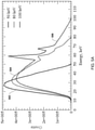
- FIG. 5B is a graph of simulation results comparing a transmitted X-ray spectrum to the spectrum that would be measured by a pixelated detector with no charge sharing and with 40 percent charge sharing among pixel detectors.
- FIGS. 5C-5H are graphs of simulation results showing the energy spectrum of X-rays generated with an X-ray tube operation at 120 kVpp as measured by a pixelated detector in energy bins at 16, 30, 50, 70, 90 and 120 keV with a percentage of charge sharing of 0%, 20%, 40%, 60%, 80% and 100%, respectively.
- FIGS. 5I-5N are graphs of simulation results showing the energy spectrum of X-rays generated with an X-ray tube operation at 120 kVpp that have passed through a 1 mm thick copper filter as measured by a pixelated detector in energy bins at 16, 30, 50, 70, 90 and 120 keV with a percentage of charge sharing of 0%, 20%, 40%, 60%, 80% and 100%, respectively.
- FIG. 6 is a graph of simulation results illustrating how a flat X-ray spectrum might be measured by a pixelated detector with no charge sharing and with 100% charge sharing.
- FIG. 7 is a graph illustrating how photon energies within a narrow band or slice of energy (dE) of a notional flat X-ray spectrum would be spread across lower energies due to effects of charge sharing.
- FIG. 8 is a graph illustrating how photon energies within multiple energy slices (dE) of a notional flat X-ray photon energy spectrum spread across lower energies add up to produce a measured X-ray photon energy spectrum that differs from the incident X-ray photon energy spectrum due to effects of charge sharing.
- FIG. 9 is a graph illustrating a measured X-ray photon energy spectrum resulting from 100 percent (%) charge sharing of detected photons of an incident flat X-ray spectrum due to effects of charge sharing.
- FIG. 10 is a graph illustrating a measured X-ray photon energy spectrum resulting from 70 percent (%) charge sharing of detected photons of an incident flat X-ray spectrum due to effects of charge sharing.
- FIG. 11 is a graph illustrating how X-ray photon energies within multiple energy slices (dE) of a typical X-ray photon energy spectrum are spread across lower energies and add up to produce a measured X-ray photon energy spectrum that differs from the incident X-ray photon energy spectrum due to effects of charge sharing.
- FIG. 12 is a graph illustrating an example of how the X-ray energy spectrum shown in FIG. 11 might be measured by a pixelated detector due to charge sharing effects.
- FIG. 13 is a process flow diagram illustrating a method of determining the energy resolution of a pixelated detector and the percentage of charge sharing that occurs in the pixelated detector according to some embodiments.
- FIG. 14 is a process flow diagram illustrating a method of compensating for charge sharing as well as other phenomena affecting a measure X-ray energy spectrum recorded by a pixelated detector according to some embodiments.
- FIG. 15 is a component block diagram illustrating an example server suitable for use with the various embodiments.
- Various embodiments improve on imaging X-ray detectors by compensating for the effects of charge sharing in a pixelated detector.
- the energy resolution and the percentage of charge sharing (PCS) characteristics of a pixelated detector are determined.
- PCS charge sharing
- effects of detector absorption, spectrum hardening from filter or target absorption, and other effects are taken into account before a charge sharing algorithm is used to determine the number of photons in each energy bin resulting from charge sharing.
- the process may be repeated as require to establish a full correlation between measured X-ray spectrum in finite energy bins after charge sharing and the energy of X-ray photons before charge sharing effects.
- an estimate of the actual X-ray spectrum before charge sharing effects can be estimated based on the X-ray spectrum measured by a pixelated detector.
- FIG. 1A is a functional block diagram of an X-ray imaging system 100 in accordance with various embodiments.
- the X-ray imaging system 100 may include an X-ray source 110 (i.e., a source of ionizing radiation), and a radiation detector 120 .
- the X-ray imaging system 100 may additionally include a support structure 105 , such as a table or frame, which may rest on the floor and may support an object 10 to be scanned.
- the support structure 105 may be stationary (i.e., non-moving) or may be configured to move relative to other elements of the X-ray imaging system 100 .
- the object 10 may be a component or material that is the subject of non-destructive testing (NDT), a biological (e.g., human patient) object, or an inanimate object (e.g., luggage) to be scanned.
- NDT non-destructive testing
- the X-ray source 110 is configured to deliver ionizing radiation to the radiation detector 120 by emitting an X-ray beam 107 toward the object 10 and the radiation detector 120 . After the X-ray beam 107 is attenuated by the object 10 , the beam of radiation 107 is received by the radiation detector 120 .
- the radiation detector 120 may be controlled by a high voltage bias power supply 124 that selectively creates an electric field between an anode 122 and cathode 128 pair coupled thereto.
- the radiation detector 120 may include CdZnTe (CZT) material disposed between the anode 122 and cathode 128 and thus configured to be exposed to the electrical field therebetween.
- a read-out application specific integrated circuit (ASIC) 130 coupled to the anode 122 and cathode 128 pair may receive signals (e.g., charge or current) from the anode 122 and be configured to provide data to and by controlled by a control unit 170 .
- the radiation detector 120 may be segmented or configured into a large number of small “pixel” detectors.
- the radiation detector 120 pixel detectors and the ASIC 130 are configured to output data that includes counts of photons detected in each pixel detector in each of a number of energy bins.
- energy detectors 120 of various embodiments provide both two-dimensional detection information regarding where photons were detected, thereby providing image information, and measurements of the X-ray energy of the detected photons.
- the control unit 170 may be configured to synchronize the X-ray source 110 , the read-out ASIC 130 , and the high voltage bias power supply 124 .
- the control unit 170 may be coupled to and operated from a computing device 160 .
- the computing device 160 and the control unit 170 may be integrated together as one device.
- the object 10 may slowly pass between the X-ray source 110 and the radiation detector 120 or alternatively the object may remain stationary while the X-ray source 110 and the radiation detector 120 move relative to the object 10 . Either way, the radiation detector 120 may capture incremental cross-sectional profiles of the object 10 .
- the data acquired by the radiation detector 120 may be passed along to the computing device 160 that may be located remotely from the radiation detector 120 via a connection 165 .
- the connection 165 may be any type of wired or wireless connection. If the connection 165 is a wired connection, the connection 165 may include a slip ring electrical connection between any structure supporting the radiation detector 120 and a stationary support part of the support structure 105 , which supports any part (e.g., a rotating ring).
- the radiation detector 120 may contain any suitable wireless transceiver to communicate data with another wireless transceiver that is in communication with the computing device 160 .
- the computing device 160 may include processing and imaging applications that analyze each profile obtained by the radiation detector 120 , and a full set of profiles may be compiled to form two-dimensional images of cross-sectional slices of the object 10 .
- X-ray imaging systems may be designed in various architectures and configurations.
- an X-ray imaging system may have a helical architecture.
- the X-ray source and detector array are attached to a freely rotating gantry.
- a table moves the object smoothly through the scanner creating helical path traced out by the X-ray beam.
- Slip rings enable the transfer of power and data on and off the rotating gantry.
- the X-ray imaging system may be a tomosynthesis X-ray imaging system.
- the gantry may move in a limited rotation angle (e.g., between 15 degrees and 60 degrees) in order to detect a cross-sectional slice of the object.
- the tomosynthesis X-ray scanner may be able to acquire slices at different depths and with different thicknesses that may be constructed via image processing.
- FIG. 1B illustrates components of an X-ray imaging system, including components within the ASIC 130 configured to count X-ray photons detected in each pixel detector within a set of energy bins.
- energy bin and “bin” refer to a particular range of measured photon energies between a minimum energy threshold and a maximum energy threshold.
- a first bin may refer to counts of photons determined to have an energy greater than a threshold energy (referred to as a trigger threshold) and less than 20 keV
- a second bin may refer to counts of photons determined to have an energy greater than 20 keV and less than 40 keV, and so forth.
- X-rays 107 from an X-ray tube 110 may be attenuated by a target 107 before interacting with the radiation detector material within the pixelated detector array 120 .
- An X-ray photon interacting (e.g., via the photoelectric effect) with a pixelated radiation detector material generates an electron cloud within the material that is swept by an electric field to an anode electrode.
- the charge gathered on the anode creates a signal that is integrated by a charge sensitive amplifier (CSA) 131 .
- CSA charge sensitive amplifier
- the voltage of the CSA output signal may be proportional to the energy of the X-ray photon.
- the output signal of the CSA may be processed by an analog filter or shaper 132 .
- the filtered output may be connected to the inputs of a number of analog comparators 134 , with each comparator connected to a digital-to-analog converter (DAC) 133 that inputs to the comparator a DAC output voltage that corresponds to the threshold level defining the limits of an energy bin.
- the detector circuitry 130 may be configured so that after the CSA voltage has stabilized (after the dead time), that voltage may be between two voltage thresholds set by two DACs 133 , which determines the output of the comparators 134 .
- Outputs from the comparators 134 may be processed through decision gates 137 , with a positive output from a comparator 134 corresponding to a particular energy bin (defined by the DAC output voltages) resulting in a count added to an associated counter 134 for the particular energy bin.
- each energy bin counter 135 Periodically, the counts in each energy bin counter 135 are output in signals 138 to the control unit 170 .
- the detector array of an X-ray imaging system may include an array of radiation detector elements, referred to herein as pixel detectors.
- the signals from the pixel detectors may be processed by a pixel detector circuit, which may sort detected photons into energy bins based on the energy of each photon or the voltage generated by the received photon.
- a pixel detector circuit which may sort detected photons into energy bins based on the energy of each photon or the voltage generated by the received photon.
- the X-ray photon count for its associated energy bin is incremented. For example, if the detected energy of an X-ray photon is 24 kilo-electron-volts (keV), the X-ray photon count for the energy bin of 20-40 keV may be incremented.
- the number of energy bins may range from one to several, such as two to six.
- an X-ray photon counting detector may have four energy bins: a first bin for detecting photons having an energy between 20 keV and 40 keV, a second bin for detecting photons having an energy between 40 keV and 60 keV, a third bin for detecting photons having an energy between 60 keV and 80 keV, and a fourth bin for detecting photons having an energy above 80 keV.
- a scanned object is exposed to an X-ray beam and attenuated photons from the X-ray beam are detected and counted by individual radiation detector pixels in a detector array.
- the X-ray beam may be heavily attenuated, and the number of photons detected by the detector array may be orders of magnitude less than the number of photons emitted from an X-ray source.
- the radiation detector can be exposed to a direct X-ray beam without an intervening object located inside the X-ray imaging system.
- the X-ray photon count rates in the X-ray imaging system may reach values of 100 million counts per second per square millimeter (Mcps/mm 2 ) or more.
- the detector array may be capable of detecting such a wide range of photon count rates.
- FIG. 2 is a top view of a portion of a pixelated radiation detector array 200 showing the plurality of pixels 202 a - 202 aa formed by the anodes 206 a 206 aa positioned on the CZT semiconductor crystal 208 .
- an X-ray 220 a interacts with atoms of the CZT semiconductor crystal 208 within the boundaries of a pixel detector defined by an anode 202 f
- the electrons within the cloud of ejected electrons 224 a are gathered on the anode 206 f and recorded as a count.
- the number of electrons (i.e., charge) collected on the anode 206 f is reflective of the energy of the incoming photon, and thus a measurement of the energy of the detected photon can be determined from the charge or current detected on the anodes.
- the electrons within the generated electron cloud 224 b may be shared between the anodes of the two adjacent pixels 202 c , 202 d .
- the net charge collected by each pixel detector anode 202 c , 202 d will be a fraction of the total number of electrons ejected by the photon absorption event.
- the electron cloud charge may be shared by more than two pixel detectors, such as illustrated with the example photon 220 c .
- the photon interacts near or at the corner of four anodes 202 d , 202 e , 202 i , 202 j , resulting in sharing of the electron cloud 224 c among the four adjacent anodes.
- a single photon interaction in this example results in four counts in four adjacent pixel detectors, with each recording a count in an energy bin lower than would be the case if there was no charge sharing (as in the example of photon 220 a ).
- charge sharing between pixel detectors results in more counts than actual photon interactions, but with energies (or in energy bins) lower than that of the incident photons. Further, charge sharing may result in uncertainty in the location of the photon interaction.
- FIGS. 3A and 3B provide cross-sectional representations of pixel detectors further illustrating the charge sharing phenomenon.
- FIG. 3A illustrates a cross-sectional view of two pixels 202 a , 202 b within a CZT radiation detector array 200 .
- a detector 200 may include a sheet of CZT semiconductor crystal 208 on which are applied to a cathode 204 and the anodes 206 a , 206 b that define each pixel 202 a , 202 b .
- the anodes 206 a , 206 b may be spaced apart by an inter-pixel gap 210 .
- the thickness of the CZT semiconductor crystal 208 may range from 1 mm to 20 mm
- the anodes 206 a , 206 b may have a side dimension of 0.1 mm to 3 mm
- the inter-pixel gap 210 may range from 0.01 mm to 0.5 mm.
- the term “cloud” is used to highlight the fact that the physical size of the electron charge is not a point but approximately a sphere with a certain radius.
- Each X-ray photon absorbed in the CZT detector generates several thousands of electrons, so even the initial charge has finite physical dimensions.
- the number of generated electrons can be estimated by dividing the incoming photon energy by the CZT ionization energy of 4.64 eV. For example, an X ray photon with an energy of 140 keV will produce about 30,000 electrons in the conduction zone, collectively carrying a charge of approximately 4.8 femto coulombs (fC).
- a detector may be configured with a timer that controls when the charge on the anode should be registered as a signal indicative of the energy of the detected photon.
- a threshold circuit coupled to each anode 206 may start such a timer when the charge on the anode exceeds a certain minimum threshold. The timer may then run for a brief period of time, referred to as a “dead time” time, during which charge is allowed to collect on the anode before the amount of charge is read by a CSA 131 .
- pile up detection event In a high flux application, such as any of a number of X-ray imaging systems (e.g., an X-ray scanner), there is a significant probability that a second photon may be absorbed in the detector pixel during the dead time resulting in what is referred to herein as a pile up detection event. Unlike charge sharing, pile up events result in two photons counted as one photon detection with a total energy that is greater than either of the photons.
- an incident photon 220 is reflected in the number of electrons in the cloud that are collected by the anodes 206 a , 206 b .
- the location of detection events and the measured energy of such events depends upon the location in the detector where energy is deposited from various photon-matter interactions. For example, as illustrated in FIG. 3B , an X ray photon 220 entering the detector 200 near the boundary of a detector pixel or within an inter-pixel gap 210 and undergoing a photoelectric absorption interaction 222 will result in a cloud of electrons 224 (and holes 225 ) that will be motivated by the electric field generated by the neighboring anodes 206 a , 206 b .
- the electron cloud 224 drifts towards the anodes 206 a , 206 b , expanding due to mutual repulsion, a portion 226 a of the electrons will be collected by one anode 206 a and a portion 226 b of the electrons will be collected by the neighboring anode 206 b . Also, some electrons in the cloud 224 may interact with surface effects within the gap 210 between anodes 206 a , 206 b , and not be collected by either anode.
- an X ray photon 220 entering the detector 200 near the boundary of a detector pixel or within the inter-pixel gap 210 will result in signals in two detector pixels 202 a , 202 b , with each measured signal being a fraction of the total charge (i.e., electron cloud 224 ) created by the photoelectric effect interaction 222 .
- Such an event is referred to herein as a charge sharing detection event.
- FIGS. 4A and 4B Various methods for resolving the locational ambiguity caused by charge sharing may be used. On method is illustrated in FIGS. 4A and 4B . Referring to FIG. 4A , an X-ray photon interacting with the detector near a corner of a pixel detector 402 may result in the electron cloud 222 being shared among the three adjacent pixel detectors 404 , 406 , 408 .
- the pixel detector 402 in which the X-ray photon was absorbed recorded an accumulated charge of 1.2 femto-Coulombs (fC)
- side adjacent pixel detectors 404 and 406 recorded accumulated charges of 0.3 fC
- the corner-adjacent pixel detector 408 recorded an accumulated charge of 0.1 fC.
- a processor coupled to the detector may be configured to recognize when two to four adjacent pixel detectors record an accumulated charge nearly simultaneously, such as within the dead time of the ASIC, and then allocate the charge of each of those pixel detectors to the one pixel detector that recorded the highest accumulated charge.
- the system To retain the energy information of the incoming photons, the system must recognize that a single photon event has spread its charge into a cluster of pixels, determine where the photon has most likely landed (usually selected as the pixel with the largest charge deposition), and assign all surrounding charge to that single pixel. This is illustrated in FIG. 4B in which the charges accumulated in each of the recording pixel detectors 402 , 404 , 406 and 408 are added and allocated to pixel detector 402 because its 1.2 fC recorded charge was highest.
- a typical approach to this problem is to sum the charge in the detector as implemented in ASIC read-out electronics chips (e.g., the Medipix-3 for example).
- the analog charge may be summed in a 2 ⁇ 2 cluster before being compared to the detection threshold.
- This method of correction can solve both true charge-sharing and the effects of fluorescence photons (discussed later).
- the advantage of this approach (compared to signal processing after quantization) is that it can handle much higher interaction rates and also that even charges below the detection threshold may be summed as long as one pixel is triggered.
- this correction since this correction has to be implemented in the ASIC architecture, this method complicates the chip design and is less flexible (e.g., it is hard-wired).
- Various embodiments provide methods to counter charge-sharing effects by measuring the affect and reversing the changes it is creating in an iterative reconstruction process.
- PCS Planar Biharmonic Sensor Suppression
- HV high-voltage
- Detectors with smaller pixels have higher PCS and at some very small pitch values below 100 um PCS reaches 100%, meaning that all photon events result in the charge cloud being split between multiple pixel detectors.
- pixelated detectors with larger pixels experience smaller numbers of charge0-shared events.
- charge-sharing reconstructions will be beneficial in all designs of pixelate detectors, although the relative importance of the charge sharing effect increases for detector pitches below the 500 um range.
- the following phenomena can affect the X-ray energy spectrum measured by a pixelated detector in an X-ray imaging system: incomplete photon absorption within the detector due to finite thickness of the CZT sensor; beam hardening effects due to low energy photons being absorbed by the filter or object under inspection; the finite energy resolution (ER) characteristics of the CZT sensor; charge-sharing between pixel detectors of some photon detection events; X-ray fluorescence; and multiple photon interactions within the response time of detector circuitry (referred to herein as “pile-up” effects).
- the effects of these phenomena may be taken into account when determining what the measured X-ray spectrum should look like depending on the energy and current applied to the X-ray tube, characteristics of the detector array (e.g., materials and pixel size), and the object placed between the X-ray tube and the detector.
- FIG. 5A illustrates the transmitted X-ray spectra for different X-ray tube voltages typically used in NDT applications.
- Characteristic X-ray count peaks are visible at X-ray tube voltages of 80 keV and 100 keV, but not at X-ray tube voltages of 50 keV due to a tungsten target being used in the X-ray tube. This is because the tungsten characteristic peaks are at 59 keV and 67 keV.
- CZT detector One factor that has a significant impact on the recorded X-ray spectrum is the finite absorption characteristics of the detector. If a CZT detector was thick enough, the detector material would absorb and thus detect all incoming X-ray photons. However, in practice the CZT thickness is limited to a thickness that is acceptable to avoid polarization effects. Typical thickness for high-flux CZT detector is 2 mm, but somewhat thinner (1.6 mm) and thicker (2.2 mm) sensors are being used as well. For example, for X-ray photons of 100 keV the stopping probability is only 50% at 1 mm thickness of CZT but increases to 76% at 2 mm and reaches 88% at 3 mm.
- FIG. 5B shows how a transmitted X-ray spectrum (dotted line 510 ) may be measured by a CZT detector (dotted line 512 ) due to incomplete absorption.
- FIG. 5B shows simulations of the X-ray spectra (dashed line 510 ) transmitted by an X-ray tube with a voltage of 80 keV, the detected X-ray spectrum with no charge-sharing (dashed line 512 ), and the detected X-ray spectrum with charge-sharing (dashed line 514 ) that assumes that 40% of all photons are charge-shared among pixel detectors.
- the energy spectrum of the X-ray photons is measured by counting the number of photons detected in each of the number of energy bins. This is illustrated in FIG. 5C , which shows the energy spectrum of X-rays generated within X-ray tube operating at 120 kVpp as measured by a CZT pixelated detector in energy bins at 16, 30, 50, 70, 90 and 120 keV assuming no charge sharing.
- FIG. 5C shows the energy spectrum of X-rays generated within X-ray tube operating at 120 kVpp as measured by a CZT pixelated detector in energy bins at 16, 30, 50, 70, 90 and 120 keV assuming no charge sharing.
- the effect of charge sharing on the X-ray energy spectrum measured with a finite number of energy bins can be seen by comparing the energy spectrum illustrated FIG. 5C with the energy spectra illustrated in FIGS.
- 5B-5H which show the measured energy spectrum of X-rays with charge sharing percentages of 20%, 40%, 60%, 80% and 100%, respectively.
- charge sharing results in reduced counts in the higher energy bins and increased counts in the lower energy bins, as the energy of single photons a recorded and multiple pixel detectors based on the respective amount of shared charge.
- the energy resolution (ER) of the detector is the energy resolution (ER) of the detector.
- the spectral X-ray detector sub-system measurements are limited by the energy resolution resulting from imperfect CZT sensor and the ASIC electronics. Typical values of the energy resolution span a range of 6 to 12 keV.
- the non-zero energy resolution causes broadening of the energy bins as photons having an energy within the energy resolution of a bin threshold (i.e., near the minimum or maximum energy bounds of the energy bin) may be recorded in the next lower or higher energy bin.
- An effect that can impact the recorded X-ray spectrum is X-ray fluorescence.
- the impact of X-ray fluorescence on the measured X-ray spectra can be similar to charge sharing. In practice it is typically difficult to distinguish between X-ray fluorescence and charge sharing effects and they can effectively be lumped together and treated together through the same analysis as described herein.
- the resulting K-shell vacancy will be filled by an electron, which emits an X-ray that carries energy away from the initial interaction site but will undergo photoelectric absorption elsewhere in the crystal.
- the vacancy will be immediately filled by an electron that emits a fluorescence X-ray.
- the fluorescence X-ray carries energy away from the initial interaction site before that X-ray interacts with an electron of another atom, such as in a photoelectric absorption that creates another electron cloud some distance from the initial electron cloud.
- the fluorescence X-ray from a K-shell absorption causes some spreading of the cloud of electrons formed in the CZT detector.
- the products of these low-energy interactions will have a range of less than 5 ⁇ m, and thus, practically, will not contribute to the spreading of the electron cloud.
- the X-ray shell energy of zinc (Zn) is too low for a fluorescent X-ray of a Zn atom to travel more than few ⁇ m before being absorbed.
- Zn zinc
- Cd Cadmium
- Te Tellurium
- a K-shell fluorescent X-ray emission will be absorbed within about 50 ⁇ m from the origin, which may somewhat inflate the primary electron cloud by such effects, although not uniformly since there is a large ratio of non-K-shell scattering events.
- Compton Scattering Another effect that can impact the recorded X-ray spectrum is Compton Scattering.
- X-ray energies of interest in NDT imaging only about 2.5% of X-ray photons of 70 keV will be Compton Scattered (also referred to as incoherent scattering), although this percentage will increase to 12% for X-ray photons of 120 keV.
- Compton Scattered also referred to as incoherent scattering
- ASIC circuitry that measures and records photon detections.
- the ASIC circuitry that detects and records photon detections is configured to wait a short period of time following sensing of an increase in voltage on a detector anode to enable the full electron cloud to migrate to the anode, and thus provide a measure of the full energy of the photon.
- a second (or third) photon may interact with the same detector pixel in what is referred to as a “pile up” event.
- a pile up event results in the anode collecting charge from two (or more) electron clouds by the end of the dead time. In such events, a single detection event is counted with an energy greater than that of the first interacting photon. Thus, pile up effects distort the X-ray spectra by increasing counts at high energies. The probability of pile up events depends on the X-ray flux, the size of the pixel detector, and the dead time of the ASIC circuitry that measures and records photon detections.
- Pile up effects can be minimized by measuring the X-ray spectra under low (mA) X-ray tube currents (i.e., low X-ray flux) conditions, thereby enabling X-ray spectra model validation without the influence of pile-up effects.
- Non-destructive testing is typically done under conditions that result in little to no pile up events.
- a pile-up model may be needed. In such cases, pile-up modeling and an appropriate correction for such effects may be developed concurrently with charge-sharing corrections.
- FIG. 5B shows simulations of the X-ray spectra (dashed line 510 ) transmitted by an X-ray tube with a voltage of 80 keV, the detected X-ray spectrum with no charge-sharing (dashed line 512 ), and the detected X-ray spectrum with charge-sharing (dashed line 514 ) that assumes that 40% of all photons are charge-shared among pixel detectors.
- the energy spectrum of the X-ray photons is measured by counting the number of photons detected in each of the number of energy bins. This is illustrated in FIG. 5C , which shows the energy spectrum of X-rays generated within X-ray tube operating at 120 kVpp as measured by a CZT pixelated detector in energy bins at 16, 30, 50, 70, 90 and 120 keV assuming no charge sharing.
- FIG. 5C shows the energy spectrum of X-rays generated within X-ray tube operating at 120 kVpp as measured by a CZT pixelated detector in energy bins at 16, 30, 50, 70, 90 and 120 keV assuming no charge sharing.
- the effect of charge sharing on the X-ray energy spectrum measured with a finite number of energy bins can be seen by comparing the energy spectrum illustrated FIG. 5C with the energy spectra illustrated in FIGS.
- 5B-5H which show the measured energy spectrum of X-rays with charge sharing percentages of 20%, 40%, 60%, 80% and 100%, respectively.
- charge sharing results in reduced counts in the higher energy bins and increased counts in the lower energy bins, as the energy of single photons a recorded and multiple pixel detectors based on the respective amount of shared charge.
- Attenuation filters are used to regulate the dose to the subject of examination.
- Bow-tie filters are used to limit exposure at the edges of the field-of-view (FoV).
- K-edge filters are used to separate low and high energy photons.
- Signal attenuation and related beam hardening are also significant consequences of measuring the object in the scanner.
- simple filters of copper foil or similar medium like lead are used.
- FIGS. 5I-5N show the energy spectrum of X-rays generated with an X-ray tube operation at 120 kVpp that have passed through a 1 mm thick copper filter as measured by a CZT pixelated detector in energy bins at 16, 30, 50, 70, 90 and 120 keV with a percentage of charge sharing of 0%, 20%, 40%, 60%, 80% and 100%, respectively.
- FIGS. 5I-5N show the energy spectrum of X-rays generated with an X-ray tube operation at 120 kVpp that have passed through a 1 mm thick copper filter as measured by a CZT pixelated detector in energy bins at 16, 30, 50, 70, 90 and 120 keV with a percentage of charge sharing of 0%, 20%, 40%, 60%, 80% and 100%, respectively.
- These figures show how the counts in lower energy bins are suppressed compared to the counts in the higher energy bins, particularly when there is no charge sharing as in the example illustrated in FIG. 5I .
- Charge sharing tends to have the opposite
- Charge sharing has the effect of causing some of the energy of the detected photon to be recorded in two or more pixel detectors, with the amount of energy shared ranging from 100% to 0% based on several factors, including how close to the boundary of a pixel detector that the photon is absorbed.
- the share of energy of photons detected with charge sharing in every small portion dE 702 at energy E i of the X-ray energy spectrum 604 is distributed uniformly.
- 60 kEV photons detected with 100% charge sharing would exhibit a flat detected energy distribution from 59 kEV to 1 kEV, such that each 60 kEV photon would be recorded as split into 59+1, 58+2 . . . 30+30 . . . 2+58, 1+59 keV (assuming 1 keV intervals) etc.
- Each incremental slice contribution to the charge-shared spectra Y(Energy) can be expressed as dE/E i .
- each small portion dE at energies E x 702 , E y 802 , and E z 812 of the X-ray photon energy spectrum would result in a flat distribution of detected energies 704 , 804 , 814 from 0 kEV up to the energy of the slice dE.
- the count of photons in energy slice dE at energy E x equal to dE*N 0 , would be spread over energies from 0 to energy E x as illustrated in the flat distribution of counts 704 of value dE/E x *N 0 .
- the count of photons in energy slice dE at energy E y would be spread over energies from 0 to energy E y as illustrated in the flat distribution of counts 804 of value dE/E y *N 0 .
- the count of photons in energy slice dE at energy E z would be spread over energies from 0 to energy E z as illustrated in the flat distribution of counts 814 of value dE/E z *N 0 .
- the flat distribution of energies 704 for each energy increment dE would be equal to 2N 0 *dE/E i .
- the spread of energies due to charge sharing for each photon energy increment E from energy 0 to E is determined and summed for all energies E across the incident energy spectrum (i.e., from E 1 to E 2 ). If the energy spectrum is defined by a formula, such as the flat energy spectrum 602 illustrated in FIGS. 6-8 , then this calculation can be accomplished by integration.
- This calculated observed energy spectrum 902 due to 100% charge sharing is illustrated in FIG. 9 .
- the detected energy spectrum would be the spectrum due to charge sharing times the fraction ⁇ of detections involving charge sharing plus the energy spectrum of the incident photons times the fraction (i ⁇ ) of photons detected without charge sharing.
- a notional measured X-ray photon energy spectrum 1002 resulting from 70% charge sharing (i.e., 30% of photon detections do not involve charge sharing) is illustrated in FIG. 10 .
- the detected energy spectrum with charge sharing may be estimated by determining the distribution of energy due to charge sharing of an increment of energies dE about an energy E, and summing the results for all dE's within the bounds of the incident spectrum. This is illustrated in FIG. 11 , which shows how the number of photons within increments dE at energies E x , E y and E z (illustrated in bars 1102 , 1112 and 1122 ) between 20 keV and 120 keV are spread over the range between zero and E 1 (illustrated as layers 1104 , 1114 and 1124 , respectively), and added.
- the result may be an observed energy spectrum that is shifted to lower energies with an increased total count of photons (since one photon may be counted in 2, 3 or 4 pixel detectors due to charge sharing).
- FIG. 13 illustrates a method 1300 that may be used to determine the energy resolution (ER) and PCS parameters for a given detector.
- the method 1300 may be performed as part of a calibration process of a manufactured detector, or may be performed to determine the PCS parameter of a detector design.
- the X-ray spectrum of an isotope with a specific or narrow energy X-ray emission may be measured by the detector.
- the energy resolution (ER) of the detector may be determined such as by using the full-width half-max value (FWHM) of the peak in the measured energy spectrum as a measure of the energy resolution.
- FWHM full-width half-max value
- X-rays emitted at the specific energy X-ray emission exhibit a narrow range of energies (broadened due to thermal and quantum effects).
- the detector would record a very narrow range of energies centered about the specific energy of the X-ray emission.
- a measure of the energy resolution of the detector may be made by determining the width or range of photon energies recorded by the detector at a count-rate in the measure photon energy spectrum that is half way between zero and the maximum counts at or near the specific energy of the X-ray emissions of the isotope.
- the measured spectrum may be analyzed to measure the spectral tail below the peak emission(s) to determine the percentage of charge sharing events occurring in the detector.
- the effects of charge sharing are obvious in the detected energy spectrum below the isotope's X-ray energy peak, particularly within the measured spectrum that is less than the energy of the isotope's characteristic X-ray plus half of the energy resolution of the detector determined in operation 1302 .
- the percentage of charge sharing events may be determined as a ration of the measured total energy in the spectral tail to the total energy measured (i.e., spectral tail plus peak emission).
- the percentage of charge sharing parameter of the pixelated detector may be determined by using the pixelated detector to measure X-ray photon energies emitted by an isotope with a specific energy X-ray emission, such as Am-241 and or Co-57, and determining the fraction of photon detection counts with energies less than the specific energy X-ray emission plus half of the energy resolution to all photon detection counts including counts about the specific energy of the characteristic X-ray emission of the isotope.
- a specific energy X-ray emission such as Am-241 and or Co-57
- the energy resolution and percentage of charge sharing events determined in the method 1300 may then be used as inputs to the method 1400 illustrated in FIG. 14 for correlating detected X-ray photon energies to an emitted X-ray photon spectrum and select a number of energy bins to use or a particular application, such as nondestructive testing.
- the method 1400 may be implemented in a computing device as part of and imaging system design process, as part of a calibration process, and/or as part of configuring X-ray imaging nondestructive test equipment for particular application.
- the X-ray photon spectrum admitted from an X-ray tube may be obtained or determined, such as by simulation using a variety of available tools.
- An example of such a tool is a Siemens online simulation tool for determining the X-ray spectrum from an X-ray tube as a function of voltage and current, although other simulation tools may be used. (See https://www.oem-products.siemens-healthineers.com/X-ray-spectra-simulation).
- This simulation may use input the kVpp of the X-ray tube and the target material (Tungsten, Molybdenum, etc.).
- a low mA current (typically 1 mA for 30 cm tube to detector distance) may be assumed to ensure that the X-ray flux remains in non-pile-up regime.
- a table look up of the X-ray spectrum of a given X-ray tube at a given power level may be used.
- the X-ray photon spectrum may be adjusted by addressing the finite absorption characteristics of the detector material (e.g., CZT). For example, an efficiency or similar factor may be applied to the spectrum determined in block 1402 .
- the probability of a photon being absorbed in a particular detector depends upon the energy of the photon, the thickness of the detector, and the atoms making up the detector material.
- Detector materials including high Z atoms, such as cesium and tungsten tend to have a high probability of interacting with an X-ray photon.
- a database available from the National Institute of Science and Technology (NIST) or equivalent may be used in this calculation.
- MATLAB or equivalent code may be used to estimate the detector absorption factor.
- the detector absorption factor determined in operation 1404 may be used to account for the fact that X-ray photons that are not absorbed in the detector go uncounted, and thus represent a fraction of the spectrum that will not be measured.
- the X-ray photon spectrum may be adjusted to account for the X-ray hardening effects of a filter and/or an object under examination.
- Online tools e.g., the Siemens tool
- physical measurements of the X-ray spectrum may be made with the imaging system with and without a filter positioned in the X-ray beam.
- the X-ray photon spectrum may be adjusted to account for the effects of the energy resolution (ER) determined in operation 1302 of the method 1300 may be added.
- the energy resolution factor accounts for the inherent error in the measurement made by the detector of a given photon's energy due to a variety of effects inherent in the detector materials and the detector design.
- the exact value of energy resolution is not critical (e.g., such as not determined using the method 1300 ) as long as it is ballpark correct (+/ ⁇ 2 keV) to smooth sharp transitions that might interfere with bin assignments.
- a charge sharing model based on the PCS value determined in block 1304 of the method 1300 may be used to determine (e.g., via calculations discussed above) how the revised X-ray spectrum is shifted to greater counts at lower energies due to charge sharing based on the PCS parameter by using the calculational methods described above with reference to FIGS. 11 and 12 .
- tools such as MATLAB can be used to simulate of the X-ray spectrum will be measured by the pixelated detector due to charge sharing by incrementally shifting (smearing) the fraction of photons in each narrow slice dE of the revised energy spectrum and summing the results to obtain an anticipated measured energy spectrum (e.g., illustrated in FIG. 12 ).
- the effects of X-ray fluorescence may be added to the anticipated measured energy spectrum. As discussed above, X-ray fluorescence is generally not of significance unless the nondestructive testing makes use of X-rays with energies less than about 35 keV. If the application uses X-rays harder than this value, optional block 1312 may not be implemented. Alternatively, the effects of X-ray fluorescence may be treated as part of the anticipated measured energy spectrum.
- the effects of pileup detections may be added to the anticipated measured energy spectrum. This operation is optional because in low flux testing applications, the probability of pileup detections is small enough to be ignored.
- a number (and thus energy bands) of energy bins to be used in measuring the detected photon energies may be selected, and the anticipated measured energy spectrum may be allocated to the selected energy bins to determine the number of photons that may be counted in each energy bin after the effects of hardening, energy resolution and charge sharing.
- the resulting energy bin picture of the spectrum may be compared to the anticipated measured energy spectrum to determine the correspondence of the incident photons in the selected energy bins to the number of photons that can be expected to be counted in each of the selected energy bins.
- a different number of energy bins may be selected and the operations of block 1416 may be repeated, with the results compared until a selection of energy bins is achieved that establishes full correspondence between the observed photon energy spectrum after charge sharing and the incident photon energy spectrum (i.e., before charge sharing).
- the correspondence between the observed photon energy spectrum after charge sharing (“post-charge-sharing”) and the incident photon energy spectrum (“pre-charge-sharing”) determined in blocks 1416 and 1418 may be used as correction factors for estimating the actual spectrum of the incident X-rays in energy bins based on the actual energy bin counts as determined by the detector.
- the correspondence factor may be determined by comparing the estimated counts in each of the energy bins determined in blocks 1416 and 1418 to counts in the energy bins that would be expected for the adjusting the incident X-ray photon energy spectrum determined in block 1408 .
- the effects of charge-sharing on energy bin distributions of detected X-ray photons may be backed out or accounted for via a simple mathematical adjustment. This may provide satisfactory adjustments for charge sharing without the need for detecting charge sharing events and summing measured energies into a single pixel detector selected as the site of detection (e.g., described with reference to FIGS. 4A and 4B ).
- FIG. 16 Such a computer 1600 typically includes one or more processors 1601 coupled to volatile memory 1602 and a large capacity nonvolatile memory, such as a disk drive 1604 . As illustrated in FIG. 16 , one or more processors 1601 may be added to the computer 1600 by inserting them into the racks of the assembly.
- the computer 1600 may also include a floppy disc drive, compact disc (CD) or digital versatile disc (DVD) disc drive 1606 coupled to the one or more processors 1601 .
- the computer 1600 may also include network access ports 1603 coupled to the one or more processors 1601 for establishing network interface connections with a network 1605 , such as a local area network coupled to other computers and servers, or the Internet.
- a network 1605 such as a local area network coupled to other computers and servers, or the Internet.
- the present embodiments may be implemented in systems used for medical imaging, such as X-ray imaging, as well as for non-medical imaging applications, such as industrial inspection applications.
- Computer program code or executable instructions for execution on a programmable processor for carrying out operations of the various embodiments may be written in a high level programming language such as C, C++, C #, Smalltalk, Java, JavaScript, Visual Basic, a Structured Query Language (e.g., Transact-SQL), Perl, or in various other programming languages.
- Embodiments may be implemented as program code or processor-executable instructions stored on a non-transitory processor-readable storage medium that are configured to cause a processor coupled to a pixelated radiation detector, such as a processor or analysis unit of an X-ray imaging system, to perform operations of any of the various embodiments.
- Non-transitory processor readable storage medium may refer to machine language code (such as object code) whose format is understandable by a processor.
- Non-transitory processor-readable storage medium include any form of media used for storing program code or processor-executable instructions including, for example, RAM, ROM, EEPROM, FLASH memory, CD-ROM or other optical disk storage, magnetic disk storage or other magnetic storage devices, or any other medium that may be used to store desired program code in the form of instructions or data structures and that may be accessed by a processor or computer.
Landscapes
- Health & Medical Sciences (AREA)
- Life Sciences & Earth Sciences (AREA)
- Engineering & Computer Science (AREA)
- Medical Informatics (AREA)
- Physics & Mathematics (AREA)
- Molecular Biology (AREA)
- High Energy & Nuclear Physics (AREA)
- Heart & Thoracic Surgery (AREA)
- General Health & Medical Sciences (AREA)
- Pathology (AREA)
- Radiology & Medical Imaging (AREA)
- Biomedical Technology (AREA)
- Nuclear Medicine, Radiotherapy & Molecular Imaging (AREA)
- Biophysics (AREA)
- Surgery (AREA)
- Animal Behavior & Ethology (AREA)
- Optics & Photonics (AREA)
- Public Health (AREA)
- Veterinary Medicine (AREA)
- Spectroscopy & Molecular Physics (AREA)
- Physiology (AREA)
- Computer Vision & Pattern Recognition (AREA)
- General Physics & Mathematics (AREA)
- Measurement Of Radiation (AREA)
Abstract
Description
PCS=Number of Charge-Shared Events/Total_Events (%).
Claims (10)
Priority Applications (1)
| Application Number | Priority Date | Filing Date | Title |
|---|---|---|---|
| US16/931,800 US11246547B2 (en) | 2019-07-22 | 2020-07-17 | Compensation for charge sharing between detector pixels in a pixilated radiation detector |
Applications Claiming Priority (2)
| Application Number | Priority Date | Filing Date | Title |
|---|---|---|---|
| US201962877231P | 2019-07-22 | 2019-07-22 | |
| US16/931,800 US11246547B2 (en) | 2019-07-22 | 2020-07-17 | Compensation for charge sharing between detector pixels in a pixilated radiation detector |
Publications (2)
| Publication Number | Publication Date |
|---|---|
| US20210022695A1 US20210022695A1 (en) | 2021-01-28 |
| US11246547B2 true US11246547B2 (en) | 2022-02-15 |
Family
ID=74190401
Family Applications (1)
| Application Number | Title | Priority Date | Filing Date |
|---|---|---|---|
| US16/931,800 Active US11246547B2 (en) | 2019-07-22 | 2020-07-17 | Compensation for charge sharing between detector pixels in a pixilated radiation detector |
Country Status (1)
| Country | Link |
|---|---|
| US (1) | US11246547B2 (en) |
Cited By (1)
| Publication number | Priority date | Publication date | Assignee | Title |
|---|---|---|---|---|
| US20230404506A1 (en) * | 2022-06-13 | 2023-12-21 | Canon Kabushiki Kaisha | Radiation imaging apparatus, information processing apparatus, information processing method, and non-transitory computer-readable storage medium |
Families Citing this family (7)
| Publication number | Priority date | Publication date | Assignee | Title |
|---|---|---|---|---|
| US12468050B2 (en) * | 2020-01-27 | 2025-11-11 | The Johns Hopkins University | Direct energy windowing for photon counting detectors |
| US11255984B2 (en) * | 2020-05-07 | 2022-02-22 | Kromek Group, PLC | Photon interaction characteristics from a subset of pixels |
| US11835666B1 (en) | 2020-07-31 | 2023-12-05 | Redlen Technologies, Inc. | Photon counting computed tomography detector with improved count rate stability and method of operating same |
| US11953452B2 (en) | 2021-03-01 | 2024-04-09 | Redlen Technologies, Inc. | Ionizing radiation detector with reduced street width and improved count rate stability |
| JP7787737B2 (en) * | 2022-02-16 | 2025-12-17 | キヤノンメディカルシステムズ株式会社 | X-ray CT device, determination method, and program |
| US12350087B2 (en) | 2022-03-16 | 2025-07-08 | Redlen Technologies, Inc. | Systems and methods for measuring bone mass density using energy discriminating photon-counting X-ray detector |
| JP2024048724A (en) * | 2022-09-28 | 2024-04-09 | キヤノンメディカルシステムズ株式会社 | Medical image processing apparatus and medical image processing method |
Citations (11)
| Publication number | Priority date | Publication date | Assignee | Title |
|---|---|---|---|---|
| US7208739B1 (en) * | 2005-11-30 | 2007-04-24 | General Electric Company | Method and apparatus for correction of pileup and charge sharing in x-ray images with energy resolution |
| US20080175347A1 (en) * | 2007-01-23 | 2008-07-24 | John Eric Tkaczyk | Method and apparatus to reduce charge sharing in pixellated energy discriminating detectors |
| US20120112088A1 (en) * | 2009-06-30 | 2012-05-10 | Doug Abraham | Enhanced photon detection for scanner |
| US20170020475A1 (en) * | 2015-07-23 | 2017-01-26 | Martin Spahn | X-ray image generation |
| US20170290555A1 (en) | 2016-04-11 | 2017-10-12 | Redlen Technologies | Local storage device in high flux semiconductor radiation detectors and methods of operating thereof |
| US20170322319A1 (en) | 2016-05-03 | 2017-11-09 | Redlen Technologies, Inc. | Sub-pixel segmentation for semiconductor radiation detectors and methods of fabricating thereof |
| US20180329086A1 (en) * | 2015-11-20 | 2018-11-15 | Koninklijke Philips N.V | Detection values determination system |
| US10151845B1 (en) * | 2017-08-02 | 2018-12-11 | Texas Instruments Incorporated | Configurable analog-to-digital converter and processing for photon counting |
| US10365380B2 (en) * | 2015-08-27 | 2019-07-30 | Koninklijke Philips N.V. | Photon counting device and method |
| US20200150297A1 (en) | 2018-11-09 | 2020-05-14 | Redlen Technologies, Inc. | Charge sharing correction methods for pixellated radiation detector arrays |
| US10677942B2 (en) * | 2016-02-01 | 2020-06-09 | Shenzhen Xpectvision Technology Co., Ltd. | X-ray detectors capable of managing charge sharing |
-
2020
- 2020-07-17 US US16/931,800 patent/US11246547B2/en active Active
Patent Citations (13)
| Publication number | Priority date | Publication date | Assignee | Title |
|---|---|---|---|---|
| US7208739B1 (en) * | 2005-11-30 | 2007-04-24 | General Electric Company | Method and apparatus for correction of pileup and charge sharing in x-ray images with energy resolution |
| US20080175347A1 (en) * | 2007-01-23 | 2008-07-24 | John Eric Tkaczyk | Method and apparatus to reduce charge sharing in pixellated energy discriminating detectors |
| US20120112088A1 (en) * | 2009-06-30 | 2012-05-10 | Doug Abraham | Enhanced photon detection for scanner |
| US20170020475A1 (en) * | 2015-07-23 | 2017-01-26 | Martin Spahn | X-ray image generation |
| US10365380B2 (en) * | 2015-08-27 | 2019-07-30 | Koninklijke Philips N.V. | Photon counting device and method |
| US20180329086A1 (en) * | 2015-11-20 | 2018-11-15 | Koninklijke Philips N.V | Detection values determination system |
| US10677942B2 (en) * | 2016-02-01 | 2020-06-09 | Shenzhen Xpectvision Technology Co., Ltd. | X-ray detectors capable of managing charge sharing |
| US20170290555A1 (en) | 2016-04-11 | 2017-10-12 | Redlen Technologies | Local storage device in high flux semiconductor radiation detectors and methods of operating thereof |
| US10396109B2 (en) | 2016-04-11 | 2019-08-27 | Redlen Technologies, Inc. | Local storage device in high flux semiconductor radiation detectors and methods of operating thereof |
| US20170322319A1 (en) | 2016-05-03 | 2017-11-09 | Redlen Technologies, Inc. | Sub-pixel segmentation for semiconductor radiation detectors and methods of fabricating thereof |
| US10393891B2 (en) | 2016-05-03 | 2019-08-27 | Redlen Technologies, Inc. | Sub-pixel segmentation for semiconductor radiation detectors and methods of fabricating thereof |
| US10151845B1 (en) * | 2017-08-02 | 2018-12-11 | Texas Instruments Incorporated | Configurable analog-to-digital converter and processing for photon counting |
| US20200150297A1 (en) | 2018-11-09 | 2020-05-14 | Redlen Technologies, Inc. | Charge sharing correction methods for pixellated radiation detector arrays |
Non-Patent Citations (3)
| Title |
|---|
| U.S. Appl. No. 16/844,484, filed Apr. 9, 2020, Redlen Technologies, Inc. |
| U.S. Appl. No. 16/875,133, filed May 15, 2020, Redlen Technologies, Inc. |
| U.S. Appl. No. 16/894,063, filed Jun. 5, 2020, Redlen Technologies, Inc. |
Cited By (1)
| Publication number | Priority date | Publication date | Assignee | Title |
|---|---|---|---|---|
| US20230404506A1 (en) * | 2022-06-13 | 2023-12-21 | Canon Kabushiki Kaisha | Radiation imaging apparatus, information processing apparatus, information processing method, and non-transitory computer-readable storage medium |
Also Published As
| Publication number | Publication date |
|---|---|
| US20210022695A1 (en) | 2021-01-28 |
Similar Documents
| Publication | Publication Date | Title |
|---|---|---|
| US11246547B2 (en) | Compensation for charge sharing between detector pixels in a pixilated radiation detector | |
| US11105938B2 (en) | Time signatures and pattern matching in x-ray photon counting detectors | |
| US11701065B2 (en) | Compton scattering correction methods for pixellated radiation detector arrays | |
| JP6335120B2 (en) | Detector array and method for detecting photons | |
| US10928527B2 (en) | Charge sharing correction methods for pixelated radiation detector arrays | |
| US11372120B2 (en) | Charge sharing correction methods for sub-pixellated radiation detector arrays | |
| US11344266B2 (en) | Calibration methods for improving uniformity in X-ray photon counting detectors | |
| Ding et al. | Characterization of energy response for photon‐counting detectors using x‐ray fluorescence | |
| JP2020525064A (en) | Management of geometrical mismatch in X-ray imaging system | |
| Fan et al. | Scatter and crosstalk corrections for 99mTc/123I dual‐radionuclide imaging using a CZT SPECT system with pinhole collimators | |
| JP5039033B2 (en) | Method for X-ray and gamma-ray spectrophoton dosimetry | |
| US9851460B1 (en) | Apparatus and method for a high-flux photon-counting spectral application-specific integrated circuit (ASIC) having a charge summing mode | |
| Howansky et al. | An apparatus and method for directly measuring the depth‐dependent gain and spatial resolution of turbid scintillators | |
| Tanguay et al. | Frequency‐dependent signal and noise in spectroscopic x‐ray imaging | |
| Fritts et al. | Pulse-shape discrimination of surface events in CdZnTe detectors for the COBRA experiment | |
| US7279676B2 (en) | Position sensitive radiation spectrometer | |
| JP6656419B2 (en) | Radioactivity distribution measuring device and method | |
| JP6594643B2 (en) | A method for linearizing attenuation measurements taken by a spectroscopic sensor | |
| Gilbert et al. | Advanced algorithms for radiographic material discrimination and inspection system design | |
| EP3507620A1 (en) | Method and system for estimating the relative gain and offset of a converter | |
| Caffrey | The development and evaluation of a compton camera for imaging spent fuel rod assemblies | |
| Maad et al. | Experimental analysis of high-speed gamma-ray tomography performance | |
| Filipenko et al. | Characterization of the energy resolution and the tracking capabilities of a hybrid pixel detector with CdTe-sensor layer for a possible use in a neutrinoless double beta decay experiment | |
| Fritz et al. | CZT detectors used in different irradiation geometries: simulations and experimental results | |
| JP7320556B2 (en) | Photon interaction properties from a subset of pixels |
Legal Events
| Date | Code | Title | Description |
|---|---|---|---|
| AS | Assignment |
Owner name: REDLEN TECHNOLOGIES, INC.,, CANADA Free format text: ASSIGNMENT OF ASSIGNORS INTEREST;ASSIGNORS:INIEWSKI, KRZYSZTOF;GULIYEV, ELMADDIN;HANSSON, CONNY;SIGNING DATES FROM 20200708 TO 20200713;REEL/FRAME:053239/0970 |
|
| FEPP | Fee payment procedure |
Free format text: ENTITY STATUS SET TO UNDISCOUNTED (ORIGINAL EVENT CODE: BIG.); ENTITY STATUS OF PATENT OWNER: SMALL ENTITY |
|
| FEPP | Fee payment procedure |
Free format text: ENTITY STATUS SET TO SMALL (ORIGINAL EVENT CODE: SMAL); ENTITY STATUS OF PATENT OWNER: SMALL ENTITY |
|
| STPP | Information on status: patent application and granting procedure in general |
Free format text: DOCKETED NEW CASE - READY FOR EXAMINATION |
|
| STPP | Information on status: patent application and granting procedure in general |
Free format text: NON FINAL ACTION MAILED |
|
| STPP | Information on status: patent application and granting procedure in general |
Free format text: RESPONSE TO NON-FINAL OFFICE ACTION ENTERED AND FORWARDED TO EXAMINER |
|
| STPP | Information on status: patent application and granting procedure in general |
Free format text: NOTICE OF ALLOWANCE MAILED -- APPLICATION RECEIVED IN OFFICE OF PUBLICATIONS |
|
| STPP | Information on status: patent application and granting procedure in general |
Free format text: PUBLICATIONS -- ISSUE FEE PAYMENT VERIFIED |
|
| STCF | Information on status: patent grant |
Free format text: PATENTED CASE |
|
| FEPP | Fee payment procedure |
Free format text: ENTITY STATUS SET TO UNDISCOUNTED (ORIGINAL EVENT CODE: BIG.); ENTITY STATUS OF PATENT OWNER: LARGE ENTITY |
|
| MAFP | Maintenance fee payment |
Free format text: PAYMENT OF MAINTENANCE FEE, 4TH YEAR, LARGE ENTITY (ORIGINAL EVENT CODE: M1551); ENTITY STATUS OF PATENT OWNER: LARGE ENTITY Year of fee payment: 4 |