US11245258B2 - Optimal sparse placement of phasor measurement units and state estimation of key buses in distribution networks - Google Patents
Optimal sparse placement of phasor measurement units and state estimation of key buses in distribution networks Download PDFInfo
- Publication number
- US11245258B2 US11245258B2 US17/007,301 US202017007301A US11245258B2 US 11245258 B2 US11245258 B2 US 11245258B2 US 202017007301 A US202017007301 A US 202017007301A US 11245258 B2 US11245258 B2 US 11245258B2
- Authority
- US
- United States
- Prior art keywords
- buses
- pmus
- distribution network
- measurements
- observable
- Prior art date
- Legal status (The legal status is an assumption and is not a legal conclusion. Google has not performed a legal analysis and makes no representation as to the accuracy of the status listed.)
- Active, expires
Links
Images


Classifications
-
- G—PHYSICS
- G01—MEASURING; TESTING
- G01R—MEASURING ELECTRIC VARIABLES; MEASURING MAGNETIC VARIABLES
- G01R19/00—Arrangements for measuring currents or voltages or for indicating presence or sign thereof
- G01R19/25—Arrangements for measuring currents or voltages or for indicating presence or sign thereof using digital measurement techniques
- G01R19/2513—Arrangements for monitoring electric power systems, e.g. power lines or loads; Logging
-
- H—ELECTRICITY
- H02—GENERATION; CONVERSION OR DISTRIBUTION OF ELECTRIC POWER
- H02J—ELECTRIC POWER NETWORKS; CIRCUIT ARRANGEMENTS OR SYSTEMS FOR SUPPLYING OR DISTRIBUTING ELECTRIC POWER; SYSTEMS FOR STORING ELECTRIC ENERGY
- H02J3/00—Circuit arrangements for AC mains or AC distribution networks
- H02J3/003—Load forecast, e.g. methods or systems for forecasting future load demand
-
- H—ELECTRICITY
- H02—GENERATION; CONVERSION OR DISTRIBUTION OF ELECTRIC POWER
- H02J—ELECTRIC POWER NETWORKS; CIRCUIT ARRANGEMENTS OR SYSTEMS FOR SUPPLYING OR DISTRIBUTING ELECTRIC POWER; SYSTEMS FOR STORING ELECTRIC ENERGY
- H02J3/00—Circuit arrangements for AC mains or AC distribution networks
- H02J3/004—Generation forecast, e.g. methods or systems for forecasting future energy generation
-
- G—PHYSICS
- G06—COMPUTING OR CALCULATING; COUNTING
- G06Q—INFORMATION AND COMMUNICATION TECHNOLOGY [ICT] SPECIALLY ADAPTED FOR ADMINISTRATIVE, COMMERCIAL, FINANCIAL, MANAGERIAL OR SUPERVISORY PURPOSES; SYSTEMS OR METHODS SPECIALLY ADAPTED FOR ADMINISTRATIVE, COMMERCIAL, FINANCIAL, MANAGERIAL OR SUPERVISORY PURPOSES, NOT OTHERWISE PROVIDED FOR
- G06Q10/00—Administration; Management
- G06Q10/04—Forecasting or optimisation specially adapted for administrative or management purposes, e.g. linear programming or "cutting stock problem"
-
- H—ELECTRICITY
- H02—GENERATION; CONVERSION OR DISTRIBUTION OF ELECTRIC POWER
- H02J—ELECTRIC POWER NETWORKS; CIRCUIT ARRANGEMENTS OR SYSTEMS FOR SUPPLYING OR DISTRIBUTING ELECTRIC POWER; SYSTEMS FOR STORING ELECTRIC ENERGY
- H02J13/00—Circuit arrangements for providing remote monitoring or remote control of equipment in a power distribution network
- H02J13/12—Monitoring network conditions, e.g. electrical magnitudes or operational status
-
- H—ELECTRICITY
- H02—GENERATION; CONVERSION OR DISTRIBUTION OF ELECTRIC POWER
- H02J—ELECTRIC POWER NETWORKS; CIRCUIT ARRANGEMENTS OR SYSTEMS FOR SUPPLYING OR DISTRIBUTING ELECTRIC POWER; SYSTEMS FOR STORING ELECTRIC ENERGY
- H02J2103/00—Details of circuit arrangements for mains or AC distribution networks
- H02J2103/30—Simulating, planning, modelling, reliability check or computer assisted design [CAD] of electric power networks
- H02J2103/35—Grid-level management of power transmission or distribution systems, e.g. load flow analysis or active network management
-
- H02J2203/20—
-
- H—ELECTRICITY
- H02—GENERATION; CONVERSION OR DISTRIBUTION OF ELECTRIC POWER
- H02J—ELECTRIC POWER NETWORKS; CIRCUIT ARRANGEMENTS OR SYSTEMS FOR SUPPLYING OR DISTRIBUTING ELECTRIC POWER; SYSTEMS FOR STORING ELECTRIC ENERGY
- H02J3/00—Circuit arrangements for AC mains or AC distribution networks
- H02J3/001—Arrangements for handling faults or abnormalities, e.g. emergencies or contingencies
- H02J3/0014—Arrangements for handling faults or abnormalities, e.g. emergencies or contingencies for preventing or reducing power oscillations in networks
- H02J3/00144—Arrangements for handling faults or abnormalities, e.g. emergencies or contingencies for preventing or reducing power oscillations in networks using phasor measuring units [PMU]
-
- Y—GENERAL TAGGING OF NEW TECHNOLOGICAL DEVELOPMENTS; GENERAL TAGGING OF CROSS-SECTIONAL TECHNOLOGIES SPANNING OVER SEVERAL SECTIONS OF THE IPC; TECHNICAL SUBJECTS COVERED BY FORMER USPC CROSS-REFERENCE ART COLLECTIONS [XRACs] AND DIGESTS
- Y02—TECHNOLOGIES OR APPLICATIONS FOR MITIGATION OR ADAPTATION AGAINST CLIMATE CHANGE
- Y02E—REDUCTION OF GREENHOUSE GAS [GHG] EMISSIONS, RELATED TO ENERGY GENERATION, TRANSMISSION OR DISTRIBUTION
- Y02E40/00—Technologies for an efficient electrical power generation, transmission or distribution
- Y02E40/70—Smart grids as climate change mitigation technology in the energy generation sector
-
- Y—GENERAL TAGGING OF NEW TECHNOLOGICAL DEVELOPMENTS; GENERAL TAGGING OF CROSS-SECTIONAL TECHNOLOGIES SPANNING OVER SEVERAL SECTIONS OF THE IPC; TECHNICAL SUBJECTS COVERED BY FORMER USPC CROSS-REFERENCE ART COLLECTIONS [XRACs] AND DIGESTS
- Y02—TECHNOLOGIES OR APPLICATIONS FOR MITIGATION OR ADAPTATION AGAINST CLIMATE CHANGE
- Y02E—REDUCTION OF GREENHOUSE GAS [GHG] EMISSIONS, RELATED TO ENERGY GENERATION, TRANSMISSION OR DISTRIBUTION
- Y02E60/00—Enabling technologies; Technologies with a potential or indirect contribution to GHG emissions mitigation
-
- Y—GENERAL TAGGING OF NEW TECHNOLOGICAL DEVELOPMENTS; GENERAL TAGGING OF CROSS-SECTIONAL TECHNOLOGIES SPANNING OVER SEVERAL SECTIONS OF THE IPC; TECHNICAL SUBJECTS COVERED BY FORMER USPC CROSS-REFERENCE ART COLLECTIONS [XRACs] AND DIGESTS
- Y04—INFORMATION OR COMMUNICATION TECHNOLOGIES HAVING AN IMPACT ON OTHER TECHNOLOGY AREAS
- Y04S—SYSTEMS INTEGRATING TECHNOLOGIES RELATED TO POWER NETWORK OPERATION, COMMUNICATION OR INFORMATION TECHNOLOGIES FOR IMPROVING THE ELECTRICAL POWER GENERATION, TRANSMISSION, DISTRIBUTION, MANAGEMENT OR USAGE, i.e. SMART GRIDS
- Y04S10/00—Systems supporting electrical power generation, transmission or distribution
- Y04S10/22—Flexible AC transmission systems [FACTS] or power factor or reactive power compensating or correcting units
-
- Y—GENERAL TAGGING OF NEW TECHNOLOGICAL DEVELOPMENTS; GENERAL TAGGING OF CROSS-SECTIONAL TECHNOLOGIES SPANNING OVER SEVERAL SECTIONS OF THE IPC; TECHNICAL SUBJECTS COVERED BY FORMER USPC CROSS-REFERENCE ART COLLECTIONS [XRACs] AND DIGESTS
- Y04—INFORMATION OR COMMUNICATION TECHNOLOGIES HAVING AN IMPACT ON OTHER TECHNOLOGY AREAS
- Y04S—SYSTEMS INTEGRATING TECHNOLOGIES RELATED TO POWER NETWORK OPERATION, COMMUNICATION OR INFORMATION TECHNOLOGIES FOR IMPROVING THE ELECTRICAL POWER GENERATION, TRANSMISSION, DISTRIBUTION, MANAGEMENT OR USAGE, i.e. SMART GRIDS
- Y04S10/00—Systems supporting electrical power generation, transmission or distribution
- Y04S10/30—State monitoring, e.g. fault, temperature monitoring, insulator monitoring, corona discharge
-
- Y—GENERAL TAGGING OF NEW TECHNOLOGICAL DEVELOPMENTS; GENERAL TAGGING OF CROSS-SECTIONAL TECHNOLOGIES SPANNING OVER SEVERAL SECTIONS OF THE IPC; TECHNICAL SUBJECTS COVERED BY FORMER USPC CROSS-REFERENCE ART COLLECTIONS [XRACs] AND DIGESTS
- Y04—INFORMATION OR COMMUNICATION TECHNOLOGIES HAVING AN IMPACT ON OTHER TECHNOLOGY AREAS
- Y04S—SYSTEMS INTEGRATING TECHNOLOGIES RELATED TO POWER NETWORK OPERATION, COMMUNICATION OR INFORMATION TECHNOLOGIES FOR IMPROVING THE ELECTRICAL POWER GENERATION, TRANSMISSION, DISTRIBUTION, MANAGEMENT OR USAGE, i.e. SMART GRIDS
- Y04S40/00—Systems for electrical power generation, transmission, distribution or end-user application management characterised by the use of communication or information technologies, or communication or information technology specific aspects supporting them
- Y04S40/20—Information technology specific aspects, e.g. CAD, simulation, modelling, system security
Definitions
- Embodiments of the invention relate to power system management; more specifically, to the state estimation of a distribution network.
- PSSE Power system state estimation
- EMS Energy Management System
- Power system states can be measured in real-time by phasor measurement units (PMUs).
- PMUs phasor measurement units
- Thousands of PMUs have been deployed throughout in the North America transmission networks to monitor grid stability on high voltage transmission systems.
- a distribution network in a power grid generally has vastly more measurement points and a physical structure that requires a high measurement accuracy.
- some distribution networks have deployed a large number of low-cost PMUs, such as micro-PMUs, to perform high-accuracy phasor measurements for real-time monitoring.
- State estimation using a conventional weighted least square (WLS) estimator typically requires a large number of real-time measurements gathered by a large number PMUs. It is, however, infeasible to place PMUs at every node of a distribution network due to technical and economic constraints. Thus, the number of available real-time measurements in an existing distribution network is usually very small. There is a need for optimal placement of a limited number of PMUs in a distribution network, and to perform real-time state estimation based on the limited number of PMU measurements.
- WLS weighted least square
- a method for state estimation of a distribution network comprises the steps of: (a) obtaining measurements from a plurality of phasor measurement units (PMUs) placed at a plurality of buses in the distribution network; (b) constructing a quotient gradient system (QGS) based on a constraint set H that relates the measurements to state variables of the distribution network; (c) integrating the QGS to reach a steady state; (d) identifying one or more of the state variables whose measurement residuals violate a measurement residual constraint in the constraint set H; (e) integrating a reconstructed QGS, which is reconstructed based on the constraint set H by setting the identified one or more state variables to values of corresponding PMU measurements; (f) iterating steps of (d) and (e) until no measurement residuals violate the measurement residual constraint, to thereby obtain a solution for the state variables as the state estimation; and (g) reporting the state estimation to a control system during real-time monitoring of the distribution network.
- PMUs phas
- a non-transitory computer-readable storage medium including instructions that, when executed by a computer system, cause the computer system to perform state estimation of a distribution network.
- the computer system is operative to: (a) obtain measurements from a plurality of phasor measurement units (PMUs) placed at a plurality of buses in the distribution network; (b) construct a quotient gradient system (QGS) based on a constraint set H that relates the measurements to state variables of the distribution network; (c) integrate the QGS to reach a steady state; (d) identify one or more of the state variables whose measurement residuals violate a measurement residual constraint in the constraint set H; (e) integrate a reconstructed QGS, which is reconstructed based on the constraint set H by setting the identified one or more state variables to values of corresponding PMU measurements; (f) iterate steps of (d) and (e) until no measurement residuals violate the measurement residual constraint, to thereby obtain a solution for the state variables as the state estimation; and (g
- FIG. 1 illustrates a power system in which embodiments of the invention may operate.
- FIG. 2A , FIG. 2B , and FIG. 2C illustrate bus groups according to some embodiments.
- FIG. 3 illustrates an example of PMUs placement in a first situation according to one embodiment.
- FIG. 4 illustrates an example of PMUs placement in a second situation according to one embodiment.
- FIG. 5 illustrates an example of PMUs placement in a third situation according to one embodiment.
- FIG. 6 is a flow diagram illustrating a method for a system to perform state estimation of a distribution network according to one embodiment.
- FIG. 7 is a block diagram of a computer system according to one embodiment.
- Embodiments of the invention provide (i) an optimal placement method for the placement of PMUs in distribution networks to meet different requirements using different numbers of PMUs; and (ii) a dynamic estimation method based on a nonlinear dynamical system approach for performing state estimation (or partial state estimation) of distribution networks using a limited number of measurement devices such as PMUs or micro-PMUs.
- partial state estimation refers to the estimation of a portion of state variables at predetermined key buses based on real-time measurements.
- “State estimation” includes partial state estimation.
- An example of partial state estimation includes the estimation of voltage amplitudes and phase angles. Partial state estimation is useful for controlling specific aspects of a power system; for example, voltage control is mainly based on estimated voltage amplitudes and thermal limit control is mainly based on estimated phase angles.
- the disclosed methods by solving a nonlinear dynamical system problem, produce partial state estimation with improved accuracy over conventional methods.
- the disclosed methods can produce an accurate result based on measurements collected by a limited number of PMUs sparsely placed in a distribution network.
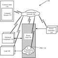
- FIG. 1 illustrates an example of a power system 100 in which embodiments of the invention may operate.
- the power system 100 includes multiple power generators 110 and electrical components 120 (such as shunt capacitors, transformers, converters, etc.), all of which are coupled to a power grid 130 that includes power transmission lines (also referred to as a transmission network) and power distribution lines (also referred to as a distribution network 135 ).
- the power generators 110 may be located in power plants and/or distributed across a geographic area.
- the power system 100 may also include renewable power generators (e.g., solar power generators, wind power generators, etc.) and multiple power storage devices (e.g., batteries) coupled to the power grid 130 . It is understood that the power system 100 may include more or fewer types of components than what is disclosed herein.
- the power grid 130 includes a transmission network to transmit high-voltage electric power from the power generators to substations.
- the substations include transformers to transform electricity from high voltage to low voltage for distribution.
- the distribution network 135 distributes low-voltage electric power to electrical load 140 , such as customers.
- the distribution network 135 includes buses, capacitors, and other electrical components.
- the distribution network 135 also includes PMUs 136 to perform real-time monitoring of the distribution network 135 .
- the PMUs 136 are placed at selected buses in the distribution network 135 to measure voltage amplitudes and phase angles of the electricity in the distribution network 135 .
- the PMUs 136 may include micro-PMUs.
- the terms “PMUs” and “micro-PMUs” may be used interchangeably, as the disclosed methods are applicable to both PMUs and micro-PMUs.
- the power system 100 also includes a control center 170 where operators of the power system 100 control the power system operations.
- An operator in the control center 170 may monitor the system status, and run computer programs on a computer system 175 to estimate the states of the system including the key buses.
- the computer system 175 may report the state estimation to the operator in the control center 170 during real-time monitoring of the distribution network.
- the estimated states of the key buses may be used to compute branch power flow (e.g., line power flow), identify nodes that have abnormal voltage (e.g., low voltage or high voltage), and compute distribution losses, etc.
- branch power flow e.g., line power flow
- identify nodes that have abnormal voltage e.g., low voltage or high voltage
- compute distribution losses etc.
- the operator may take actions to control the system including but not limited to: corrective control actions to fix issues such as abnormal voltage, abnormal line power flow, and to minimize distribution losses.
- the computer system 175 is in communication with the devices or components (including the micro-PMUs 136 ) of the power system 100 via a communication network 180 .
- the communication network 180 may be a propriety wide-area network or a public network such as the Internet protected with data encryption capabilities.
- the generators 110 , the electrical components 120 , the power grid 130 , the distribution network 135 , and the loads 140 are modeled as buses and lines in a power system analysis.
- the following description includes two parts.
- the first part of the description presents a method for placing PMUs in a distribution network (e.g., the distribution network 135 ) to meet the requirements of predetermined key buses whose states are to be accurately estimated.
- the key buses may be determined based on a system analysis or by users.
- the second part of the description presents partial state estimation of a distribution network, where the distribution network contains predetermined key buses whose states are to be accurately estimated using a limited number of PMU measurements.
- PMU and “micro-PMU” are herein used interchangeably.
- the distribution network described herein contains multiple zero-injection nodes, an effective use of zero-injection measurements can increase the number of observable nodes.
- a suitable model for inclusion of zero-injection nodes considering a three-phase network topology is described.
- Zero-injection buses When zero-injection buses are connected together, these zero-injection buses are defined as a zero-injection bus group (ZIBG).
- ZIBG zero-injection bus group
- FIG. 2A illustrates an example where bus 1 , bus 2 , and bus 3 are zero-injection buses.
- the three buses form 6 ZIBGs: ⁇ 1 ⁇ , ⁇ 2 ⁇ , ⁇ 3 ⁇ , ⁇ 1,2 ⁇ , ⁇ 2,3 ⁇ , and ⁇ 1,2,3 ⁇ .
- the term “observable bus” means that the voltage phasor (i.e., voltage amplitude and phase angle) of the bus can be estimated using a set of available measurements with a numerical method.
- a bus is observable when the bus is configured with a micro-PMU. Further, a bus is observable when its connected bus is configured with a micro-PMU and the phases of the bus are no more than that of the micro-PMU-installed bus.
- bus 1 is a zero-injection bus
- bus 1 is observable if buses 2 , 3 , and 4 are all observable.
- bus 1 and bus 2 are zero-injection buses.
- Bus 1 and bus 2 are observable if buses 3 , 4 , and bus 5 are all observable.
- an observability vector of the corresponding distribution network can be derived using the observability schemes described above.
- the observability vector is used to describe which buses in the distribution network are observable.
- X Z ⁇ x ⁇ R Z n
- the nonlinear integer optimization problem formulated in (1) and (2) can be solved by a nonlinear integer programming method; e.g., the following 3-stage group-based optimization method.
- Stage 1 Discrete particle swarm optimization. Assume that the number of micro-PMUs installed is given. A discrete particle swarm optimization (DPSO) method can be used to solve the optimal micro-PMU placement problem. In DPSO, a particle represents the buses to place micro-PMUs. The fitness function is the objective of (1). Velocity and position are the basic properties of every particle, which are updated according to the following schemes.
- v i k + 1 wv i k + c 1 * rand 1 ( ) * ( pbest i - x i k ) + c 2 * rand 2 ( ) * ( gbest i - x i k ) ( 3 )
- v i k is the ith velocity component at iteration k
- rand 1 ( ) and rand 2 ( ) are random numbers between 0 and 1
- x i k is the current position in the ith dimension
- c 1 , c 2 are the acceleration coefficients
- pbest i is the personal best position in the ith dimension
- gbest i is the global best position in the ith dimension
- w is the inertia weight factor.
- Stage 1 of the group-based optimization method can be implemented not only by the DPSO, but also by other meta-heuristic methods, such as the genetic algorithm, simulated annealing, etc.
- Stage 2 Grouping particles by clustering schemes. Cluster all of the particles into multiple groups of particles using a clustering scheme such as the k-means scheme based on the distance between vectors.
- the cluster center uses the m elements with the highest frequency in the group. It is worth noting that the order in which the elements appear does not matter. For example, for a set of vectors ⁇ [1,2,3,4,5], [1,2,4,5,6], [1,3,4,5,6], [3,4,5,6,7] ⁇ , the elements and corresponding frequencies are [1,2,3,4,5,6,7] and [3,2,3,4,4,3,1], respectively. So the cluster center is [1,3,4,5,6]. For every group, the method selects three best particles and the cluster center to form a new group to represent the group.
- Stage 3 Local optimization method. Apply a local optimization method (which can compute local optimal solutions) to each particle selected in Stage 2 to compute the corresponding local optimal solution. These local optimal solutions provide the locations and the number of micro-PMUs to be placed in the distribution network.
- a method for placing micro-PMUs provides an optimal placement scheme of micro-PMUs, which meets the requirements of different situations using different numbers of micro-PMUs placed in a distribution network.
- the OPP aims to meet the following requirement: the state of all of the key buses are to be estimated by the placement of micro-PMUs.
- the optimal micro-PMU placement is to find the minimum number of micro-PMUs and the corresponding locations for the micro-PMUs to be installed in order to observe (i.e., estimate the states of) all of the key buses; e.g., the voltage of these key buses can be estimated based on the placement of micro-PMUs.
- OPP problem formulation i.e., problem (4)
- problem (4) the solution for (4) satisfies the requirement for the first situation.
- the objective function ⁇ minimizes the number of micro-PMUs under the condition that the key buses are all observable (i.e., the constraint G k ⁇ C is satisfied).
- the details and schemes of obtaining the observability vector have been derived above.
- (v) N is the number of buses and m is the number of possible topologies.
- the OPP aims to meet the following two requirements: (1) key buses are observable (i.e., the key buses can be estimated so that real-time monitoring of these key buses is possible) by the placement of micro-PMUs, and (2) the number of observable non-key buses is as many as possible.
- (v) l is the number of micro-PMUs to be placed.
- micro-PMUs In the third situation, a specified number of micro-PMUs is given.
- the OPP aims to meet the following two requirements: (1) key buses are observable by the placement of micro-PMUs; if not, then (2) the number of observable key buses is as many as possible.
- Partial state estimation with a limited number of micro-PMU measurements After placing micro-PMUs at the locations that satisfy the requirement(s) described above in connection with the first situation, the second situation, or the third situation, the next task is to perform state estimation using measurements obtained by these micro-PMUs.
- WLS Weighted Least Squares
- Quotient Gradient System for state estimation.
- Embodiments of the invention develop and apply the trajectories of a nonlinear dynamical system, called Quotient Gradient System (QGS), to the state estimation.
- QGS Quotient Gradient System
- Partial state estimation In practical applications, users may desire to accurately estimate partial state variables, such as voltage amplitudes and voltage phase angles, at key buses.
- the disclosed partial state estimation increases the accuracy of the estimated voltage amplitude and phase angle of key buses based on the QGS methods.
- the partial state estimation problem can be formulated as follows:
- H E micro-PMU (x) represents the function vector relating micro-PMU measurements to state variables
- H E zero (x) represents the power balance functions for zero-injection power measurements
- H I micro-PMU (x) represents the measurement residual constraint function vector associated with micro-PMU measurements.
- the measurement residual constraints include voltage amplitude measurement residual constraints and voltage phase angle measurement residual constraints.
- a solution for (15) can be obtained by tracking the trajectory of the QGS to its steady state. More specifically, problem (15) can be solved by the QGS below:
- the proposed method for performing state estimation with a limited number of micro-PMU measurements is presented in the following steps.
- the state estimation is a partial state estimation that estimates state variables such as voltage amplitudes and voltage phase angles.
- the method steps described below are applicable to both PMUs and micro-PMUs.
- Step 1 Estimate the initial operating condition.
- the initial operating condition can be calculated using the last Supervisory Control and Data Acquisition (SCADA) measurements (if available), pseudo measurements (i.e., prediction and/or estimation), and virtual measurements. This calculation can use any effective known state estimation method, such as a WLS-Gauss Newton method.
- SCADA Supervisory Control and Data Acquisition
- Step 2 Construct a QGS.
- Formulate a QGS (e.g., (16)) according to a constraint set H(x) associated with measurements including micro-PMU measurements and virtual measurements.
- the constraint set H(x) is also referred to as a constraint set vector H(x).
- the constraint set H(x) includes voltage amplitude measurement residual constraints and voltage phase angle measurement residual constraints.
- Step 3 Numerical Integration of the QGS. Integrate the QGS to its steady state and obtain a state estimation solution.
- Step 4 Identify the residual violation. Examine the constraints set vector H(x) to check if the measurement residual of any state variable violates its corresponding measurement residual constraint (i.e., whether the inequality
- Step 5 Reconstruct a QGS. Set the state variable x i identified at Step 4 to its micro-PMU measurement value z i , thus removing the state variable from the list of state variables to be estimated. Then reconstruct a QGS to estimate the state variables remaining in the list, and go to Step 3.
- Step 6 Output. Output the estimated state vector (which is composed of the values of the list of estimated state variables).
- the estimated state vector includes the estimated states of key buses.
- the disclosed method as well as the apparatus and the computer product implementing the method, can be applied to partial state estimation based on measurements gathered by a limited number of micro-PMUs in a distribution network.
- the present disclosure can be applied to measurements gathered by other devices and technologies not limited to micro-PMUs.
- FIG. 6 is a flow diagram illustrating a method 600 for state estimation of a distribution network according to one embodiment.
- the method 600 may be performed by a system, such as the computer system 175 in FIG. 1 and/or a computer system 700 in FIG. 7 .
- the method 600 starts at step 610 when the system obtains PMU measurements during real-time operation of a distribution network with a plurality of PMUs placed at a plurality of buses.
- the system at step 620 constructs a QGS based on a constraint set H that relates measurements to state variables of the distribution network, wherein the measurements include at least the PMU measurements.
- the system at step 630 integrates the QGS to reach a steady state.
- the system at step 640 identifies one or more state variables whose measurement residuals violate a measurement residual constraint in the constraint set H.
- the system at step 650 integrates a reconstructed QGS, which is reconstructed from the constraint set H by setting the identified one or more state variables to values of corresponding PMU measurements (e.g., set the state variable x i to its PMU measurement value z i ).
- the system at step 660 iterates steps 640 and 650 , until no measurement residuals violate the measurement residual constraint, to obtain a solution for the state variables of the distribution network.
- the system at step 670 reports the state estimation to a control system during real-time monitoring of the distribution network.
- FIG. 7 is a diagram of a computer system 700 according to one embodiment.
- the computer system 700 may be a server computer, a multi-processor computer, or any machine capable of executing a set of instructions (sequential or otherwise) that specify actions to be taken by that machine. While only a single machine is illustrated, the term “machine” shall also be taken to include any collection of machines (e.g., computers, processors and cores) that individually or jointly execute a set (or multiple sets) of instructions to perform any one or more of the methodologies discussed herein.
- the computer system 700 includes circuitry which further includes processing circuitry 702 , a memory 704 , and interface circuitry 706 .
- the interface circuitry 700 can include at least one input port and at least one output port.
- the memory 704 contains instructions executable by the processing circuitry 702 whereby the computer system 700 is operable to perform the various embodiments as described herein, including the method 600 of FIG. 6 .
- a part or all of the data and code for performing the various embodiments described herein may be received over a communication network 750 via the network interface device 706 .
- Embodiments may be implemented as a software product stored in a machine-readable medium (such as the non-transitory machine-readable storage media, also referred to as a computer-readable medium, a processor-readable medium, or a computer-usable medium having a computer-readable program code embodied therein).
- the non-transitory machine-readable medium may be any suitable tangible medium including a magnetic, optical, or electrical storage medium including a diskette, compact disk read-only memory (CD-ROM), digital versatile disc read-only memory (DVD-ROM) memory device (volatile or non-volatile) such as hard drive or solid-state drive, or similar storage mechanism.
- the machine-readable medium may contain various sets of instructions, code sequences, configuration information, or other data, which, when executed, cause a processor to perform steps in a method according to an embodiment. Those of ordinary skill in the art will appreciate that other instructions and operations necessary to implement the described embodiments may also be stored on the machine-readable medium. Software running from the machine-readable medium may interface with circuitry to perform the described tasks.
- circuits either dedicated circuits or general-purpose circuits, which operate under the control of one or more processors and coded instructions
- the functional blocks will typically comprise transistors that are configured in such a way as to control the operation of the circuitry in accordance with the functions and operations described herein.
- FIG. 6 The operations of the flow diagram of FIG. 6 have been described with reference to the exemplary embodiments of FIGS. 1 and 7 . However, it should be understood that the operations of the flow diagram of FIG. 6 can be performed by embodiments of the invention other than the embodiments of FIGS. 1 and 7 , and the embodiments of FIGS. 1 and 7 can perform operations different than those discussed with reference to the flow diagram. While the flow diagram of FIG. 6 shows a particular order of operations performed by certain embodiments of the invention, it should be understood that such order is exemplary (e.g., alternative embodiments may perform the operations in a different order, combine certain operations, overlap certain operations, etc.).
Landscapes
- Engineering & Computer Science (AREA)
- Power Engineering (AREA)
- Physics & Mathematics (AREA)
- General Physics & Mathematics (AREA)
- Supply And Distribution Of Alternating Current (AREA)
Abstract
Description
where XZ⊂RZ n is a subset, and RZ n is a collection of all the integer points on Rn.
X Z ={x∈R Z n|1≤x i ≤m} (2)
where m is the range of each dimension. The nonlinear integer optimization problem formulated in (1) and (2) can be solved by a nonlinear integer programming method; e.g., the following 3-stage group-based optimization method.
where vi k is the ith velocity component at iteration k; rand1( ) and rand2( ) are random numbers between 0 and 1; xi k is the current position in the ith dimension; c1, c2 are the acceleration coefficients; pbesti is the personal best position in the ith dimension; gbesti is the global best position in the ith dimension; and w is the inertia weight factor. It is noted that
z=h(x)+e (7)
where z is the m×1 measurement vector, x is the n×1 vector of the state variables to be estimated, h(x) is the m×1 function vector relating measurements and state variables, and e is the m×1 measurement error vector.
min J(x)=[z−h(x)]T W −1[z−h(x)] (8)
where W=diag(σ1 2, . . . , σi 2, . . . , σm 2) represents the covariance matrix of e, and σi 2 is the standard deviation of measurement i.
min J(x)=[z−h(x)]T W −1[z−h(x)]
s.t. h zero(x)=0
|z−h(x)|−β≤0 (9)
where hzero(x) represents the power balance functions for zero injection power measurements and β is a scalar representing the measurement residual constraint.
where S represents the slack variables. However, the measurement residuals according to (10) are generally unsatisfactory.
{dot over (y)}=Q H(y)=−DH(y)T H(y)
y=(x,S) (12)
where DH(y) is the Jacobian matrix of H(y). It can be shown that when the weighed factor √{square root over (2/σi 2)} is considered, the degenerate stable equilibrium manifolds (DSEM) of the QGS are the minimum solution to the following energy function:
E(y)=H(y)T W −1 H(y). (13)
Claims (20)
Priority Applications (1)
| Application Number | Priority Date | Filing Date | Title |
|---|---|---|---|
| US17/007,301 US11245258B2 (en) | 2019-07-03 | 2020-08-31 | Optimal sparse placement of phasor measurement units and state estimation of key buses in distribution networks |
Applications Claiming Priority (2)
| Application Number | Priority Date | Filing Date | Title |
|---|---|---|---|
| US201962870613P | 2019-07-03 | 2019-07-03 | |
| US17/007,301 US11245258B2 (en) | 2019-07-03 | 2020-08-31 | Optimal sparse placement of phasor measurement units and state estimation of key buses in distribution networks |
Publications (2)
| Publication Number | Publication Date |
|---|---|
| US20210083474A1 US20210083474A1 (en) | 2021-03-18 |
| US11245258B2 true US11245258B2 (en) | 2022-02-08 |
Family
ID=74868746
Family Applications (1)
| Application Number | Title | Priority Date | Filing Date |
|---|---|---|---|
| US17/007,301 Active 2040-09-30 US11245258B2 (en) | 2019-07-03 | 2020-08-31 | Optimal sparse placement of phasor measurement units and state estimation of key buses in distribution networks |
Country Status (1)
| Country | Link |
|---|---|
| US (1) | US11245258B2 (en) |
Families Citing this family (11)
| Publication number | Priority date | Publication date | Assignee | Title |
|---|---|---|---|---|
| CN113255959B (en) * | 2021-04-09 | 2023-05-02 | 广东电网有限责任公司电力调度控制中心 | Dynamic state estimation method and system for electric power system |
| EP4160867B1 (en) * | 2021-10-04 | 2024-08-07 | Kraken Technologies Limited | Method for determining an optimal placement of measurement units for estimating the state of a physical power distribution grid |
| CN113991856B (en) * | 2021-10-29 | 2024-03-12 | 国网上海市电力公司 | A multi-adaptive μPMU optimal distribution method for micro-energy networks |
| CN115036944B (en) * | 2022-06-14 | 2025-05-23 | 天津大学 | A complete characterization method for the three-phase feasible region of the unbalanced power grid system model |
| CN115130662B (en) * | 2022-08-12 | 2024-12-20 | 电子科技大学 | A method for time-varying topological state estimation of distribution network based on transfer learning |
| WO2024055044A2 (en) * | 2022-09-09 | 2024-03-14 | General Electric Company | System and method for distributed quantum entanglement |
| CN115906353B (en) * | 2022-11-17 | 2023-08-08 | 国网上海市电力公司 | A distribution network PMU optimal configuration method based on node evaluation |
| EP4686949A1 (en) * | 2024-07-30 | 2026-02-04 | Hitachi Energy Ltd | Placement of measurement devices for observability of very large power systems |
| CN119441926A (en) * | 2024-10-23 | 2025-02-14 | 中国南方电网有限责任公司 | Power system bad data identification method and system based on random matrix and spectral clustering |
| CN119474648A (en) * | 2024-11-28 | 2025-02-18 | 中国南方电网有限责任公司 | A method and system for calculating power flow in power system |
| CN119851095B (en) * | 2025-03-19 | 2025-06-24 | 济南大学 | Inspection model training method and device based on small-batch quotient gradient system |
Citations (6)
| Publication number | Priority date | Publication date | Assignee | Title |
|---|---|---|---|---|
| US20130036311A1 (en) * | 2011-08-05 | 2013-02-07 | Battelle Memorial Institute | Intelligent sensor and controller framework for the power grid |
| US20160187399A1 (en) * | 2013-08-07 | 2016-06-30 | S.I.Sv.El. Societa' Italiana Per Lo Sviluppo Dell'elettronica S.P.A. | Method for measuring dynamics of a flow of energy and relevant device and system |
| US20160313197A1 (en) * | 2015-04-27 | 2016-10-27 | General Electric Company | System and method for non-invasive generator damping torque estimation |
| US20170214244A1 (en) * | 2016-01-27 | 2017-07-27 | Alliance For Sustainable Energy, Llc | Real time voltage regulation through gather and broadcast techniques |
| US20170336465A1 (en) * | 2016-05-19 | 2017-11-23 | Ecole polytechnique fédérale de Lausanne (EPFL) | Method and System for Fault Detection and Faulted Line Identification in Power Systems using Synchrophasors-Based Real-Time State Estimation |
| US20180217568A1 (en) * | 2015-10-07 | 2018-08-02 | University Of Utah Research Foundation | Systems and methods for managing power generation and storage resources |
-
2020
- 2020-08-31 US US17/007,301 patent/US11245258B2/en active Active
Patent Citations (6)
| Publication number | Priority date | Publication date | Assignee | Title |
|---|---|---|---|---|
| US20130036311A1 (en) * | 2011-08-05 | 2013-02-07 | Battelle Memorial Institute | Intelligent sensor and controller framework for the power grid |
| US20160187399A1 (en) * | 2013-08-07 | 2016-06-30 | S.I.Sv.El. Societa' Italiana Per Lo Sviluppo Dell'elettronica S.P.A. | Method for measuring dynamics of a flow of energy and relevant device and system |
| US20160313197A1 (en) * | 2015-04-27 | 2016-10-27 | General Electric Company | System and method for non-invasive generator damping torque estimation |
| US20180217568A1 (en) * | 2015-10-07 | 2018-08-02 | University Of Utah Research Foundation | Systems and methods for managing power generation and storage resources |
| US20170214244A1 (en) * | 2016-01-27 | 2017-07-27 | Alliance For Sustainable Energy, Llc | Real time voltage regulation through gather and broadcast techniques |
| US20170336465A1 (en) * | 2016-05-19 | 2017-11-23 | Ecole polytechnique fédérale de Lausanne (EPFL) | Method and System for Fault Detection and Faulted Line Identification in Power Systems using Synchrophasors-Based Real-Time State Estimation |
Also Published As
| Publication number | Publication date |
|---|---|
| US20210083474A1 (en) | 2021-03-18 |
Similar Documents
| Publication | Publication Date | Title |
|---|---|---|
| US11245258B2 (en) | Optimal sparse placement of phasor measurement units and state estimation of key buses in distribution networks | |
| US20220271530A1 (en) | Microgrid power flow monitoring and control | |
| Wu et al. | A robust state estimator for medium voltage distribution networks | |
| Rueda et al. | Assessment and enhancement of small signal stability considering uncertainties | |
| Hansen et al. | Power system state estimation using three-phase models | |
| US11824354B2 (en) | Online state estimation and topology identification using advanced metering infrastructure (AMI) measurements | |
| Ferdowsi et al. | A scalable data-driven monitoring approach for distribution systems | |
| Chanda et al. | Quantifying resiliency of smart power distribution systems with distributed energy resources | |
| US20140309952A1 (en) | Method for Analyzing Faults in Ungrounded Power Distribution Systems | |
| JP6575939B2 (en) | System and method for analyzing vibration stability in a power transmission system | |
| Reche et al. | Data mining-based method to reduce multiple estimation for fault location in radial distribution systems | |
| US11169188B2 (en) | Low-observability matrix completion | |
| US20210103263A1 (en) | Systems and methods for hybrid dynamic state estimation | |
| Wang et al. | Resilience enhancement strategy using microgrids in distribution network | |
| Hua et al. | Fast unscented transformation-based transient stability margin estimation incorporating uncertainty of wind generation | |
| Chakrabarti et al. | A comparative study of the methods of inclusion of PMU current phasor measurements in a hybrid state estimator | |
| Alinejad et al. | PMU-based distribution network load modelling using Harmony Search Algorithm | |
| Carpinelli et al. | Complete matrix formulation of fault-position method for voltage-dip characterisation | |
| Dwivedi | Vulnerability analysis and fault location in power systems using complex network theory | |
| CN118735071A (en) | A method and system for optimizing site selection of medium voltage DC converter stations in urban power grid | |
| Meliopoulos et al. | Distributed dynamic state estimation: Fundamental building block for the smart grid | |
| Bartolomey et al. | Super-accelerated power systems power flow and state estimation calculations within the WAMS environment | |
| Iswadi et al. | Identification of small signal oscillation mode parameters from simulated and actual PMU ringdown data | |
| Shahraeini et al. | Optimal pmu placement considering reliability of measurement system in smart grids | |
| CN113109664B (en) | A method for locating voltage sag source based on wavelet singular entropy |
Legal Events
| Date | Code | Title | Description |
|---|---|---|---|
| AS | Assignment |
Owner name: TIANJIN UNIVERSITY, CHINA Free format text: ASSIGNMENT OF ASSIGNORS INTEREST;ASSIGNORS:CHIANG, HSIAO-DONG;LV, QIANCHENG;KONG, XIANGYU;SIGNING DATES FROM 20200820 TO 20200830;REEL/FRAME:053643/0217 Owner name: BIGWOOD TECHNOLOGY, INC., NEW YORK Free format text: ASSIGNMENT OF ASSIGNORS INTEREST;ASSIGNORS:CHIANG, HSIAO-DONG;LV, QIANCHENG;KONG, XIANGYU;SIGNING DATES FROM 20200820 TO 20200830;REEL/FRAME:053643/0217 |
|
| FEPP | Fee payment procedure |
Free format text: ENTITY STATUS SET TO UNDISCOUNTED (ORIGINAL EVENT CODE: BIG.); ENTITY STATUS OF PATENT OWNER: LARGE ENTITY |
|
| STPP | Information on status: patent application and granting procedure in general |
Free format text: APPLICATION DISPATCHED FROM PREEXAM, NOT YET DOCKETED |
|
| FEPP | Fee payment procedure |
Free format text: PETITION RELATED TO MAINTENANCE FEES GRANTED (ORIGINAL EVENT CODE: PTGR); ENTITY STATUS OF PATENT OWNER: LARGE ENTITY |
|
| STPP | Information on status: patent application and granting procedure in general |
Free format text: DOCKETED NEW CASE - READY FOR EXAMINATION |
|
| STPP | Information on status: patent application and granting procedure in general |
Free format text: NOTICE OF ALLOWANCE MAILED -- APPLICATION RECEIVED IN OFFICE OF PUBLICATIONS |
|
| STPP | Information on status: patent application and granting procedure in general |
Free format text: PUBLICATIONS -- ISSUE FEE PAYMENT RECEIVED |
|
| STPP | Information on status: patent application and granting procedure in general |
Free format text: PUBLICATIONS -- ISSUE FEE PAYMENT VERIFIED |
|
| STCF | Information on status: patent grant |
Free format text: PATENTED CASE |
|
| MAFP | Maintenance fee payment |
Free format text: PAYMENT OF MAINTENANCE FEE, 4TH YEAR, LARGE ENTITY (ORIGINAL EVENT CODE: M1551); ENTITY STATUS OF PATENT OWNER: LARGE ENTITY Year of fee payment: 4 |