US11243501B2 - Machine learning device, control system, and machine learning - Google Patents
Machine learning device, control system, and machine learning Download PDFInfo
- Publication number
- US11243501B2 US11243501B2 US16/807,804 US202016807804A US11243501B2 US 11243501 B2 US11243501 B2 US 11243501B2 US 202016807804 A US202016807804 A US 202016807804A US 11243501 B2 US11243501 B2 US 11243501B2
- Authority
- US
- United States
- Prior art keywords
- machine learning
- coefficients
- unit
- value
- velocity
- Prior art date
- Legal status (The legal status is an assumption and is not a legal conclusion. Google has not performed a legal analysis and makes no representation as to the accuracy of the status listed.)
- Active, expires
Links
Images


Classifications
-
- G—PHYSICS
- G05—CONTROLLING; REGULATING
- G05B—CONTROL OR REGULATING SYSTEMS IN GENERAL; FUNCTIONAL ELEMENTS OF SUCH SYSTEMS; MONITORING OR TESTING ARRANGEMENTS FOR SUCH SYSTEMS OR ELEMENTS
- G05B13/00—Adaptive control systems, i.e. systems automatically adjusting themselves to have a performance which is optimum according to some preassigned criterion
- G05B13/02—Adaptive control systems, i.e. systems automatically adjusting themselves to have a performance which is optimum according to some preassigned criterion electric
- G05B13/0265—Adaptive control systems, i.e. systems automatically adjusting themselves to have a performance which is optimum according to some preassigned criterion electric the criterion being a learning criterion
-
- G—PHYSICS
- G05—CONTROLLING; REGULATING
- G05B—CONTROL OR REGULATING SYSTEMS IN GENERAL; FUNCTIONAL ELEMENTS OF SUCH SYSTEMS; MONITORING OR TESTING ARRANGEMENTS FOR SUCH SYSTEMS OR ELEMENTS
- G05B13/00—Adaptive control systems, i.e. systems automatically adjusting themselves to have a performance which is optimum according to some preassigned criterion
- G05B13/02—Adaptive control systems, i.e. systems automatically adjusting themselves to have a performance which is optimum according to some preassigned criterion electric
- G05B13/04—Adaptive control systems, i.e. systems automatically adjusting themselves to have a performance which is optimum according to some preassigned criterion electric involving the use of models or simulators
- G05B13/042—Adaptive control systems, i.e. systems automatically adjusting themselves to have a performance which is optimum according to some preassigned criterion electric involving the use of models or simulators in which a parameter or coefficient is automatically adjusted to optimise the performance
-
- G—PHYSICS
- G05—CONTROLLING; REGULATING
- G05B—CONTROL OR REGULATING SYSTEMS IN GENERAL; FUNCTIONAL ELEMENTS OF SUCH SYSTEMS; MONITORING OR TESTING ARRANGEMENTS FOR SUCH SYSTEMS OR ELEMENTS
- G05B19/00—Program-control systems
- G05B19/02—Program-control systems electric
- G05B19/18—Numerical control [NC], i.e. automatically operating machines, in particular machine tools, e.g. in a manufacturing environment, so as to execute positioning, movement or co-ordinated operations by means of program data in numerical form
- G05B19/19—Numerical control [NC], i.e. automatically operating machines, in particular machine tools, e.g. in a manufacturing environment, so as to execute positioning, movement or co-ordinated operations by means of program data in numerical form characterised by positioning or contouring control systems, e.g. to control position from one programmed point to another or to control movement along a programmed continuous path
-
- G—PHYSICS
- G05—CONTROLLING; REGULATING
- G05B—CONTROL OR REGULATING SYSTEMS IN GENERAL; FUNCTIONAL ELEMENTS OF SUCH SYSTEMS; MONITORING OR TESTING ARRANGEMENTS FOR SUCH SYSTEMS OR ELEMENTS
- G05B19/00—Program-control systems
- G05B19/02—Program-control systems electric
- G05B19/18—Numerical control [NC], i.e. automatically operating machines, in particular machine tools, e.g. in a manufacturing environment, so as to execute positioning, movement or co-ordinated operations by means of program data in numerical form
- G05B19/416—Numerical control [NC], i.e. automatically operating machines, in particular machine tools, e.g. in a manufacturing environment, so as to execute positioning, movement or co-ordinated operations by means of program data in numerical form characterised by control of velocity, acceleration or deceleration
-
- G—PHYSICS
- G05—CONTROLLING; REGULATING
- G05B—CONTROL OR REGULATING SYSTEMS IN GENERAL; FUNCTIONAL ELEMENTS OF SUCH SYSTEMS; MONITORING OR TESTING ARRANGEMENTS FOR SUCH SYSTEMS OR ELEMENTS
- G05B2219/00—Program-control systems
- G05B2219/30—Nc systems
- G05B2219/33—Director till display
- G05B2219/33034—Online learning, training
-
- G—PHYSICS
- G05—CONTROLLING; REGULATING
- G05B—CONTROL OR REGULATING SYSTEMS IN GENERAL; FUNCTIONAL ELEMENTS OF SUCH SYSTEMS; MONITORING OR TESTING ARRANGEMENTS FOR SUCH SYSTEMS OR ELEMENTS
- G05B2219/00—Program-control systems
- G05B2219/30—Nc systems
- G05B2219/34—Director, elements to supervisory
- G05B2219/34013—Servocontroller
-
- G—PHYSICS
- G05—CONTROLLING; REGULATING
- G05B—CONTROL OR REGULATING SYSTEMS IN GENERAL; FUNCTIONAL ELEMENTS OF SUCH SYSTEMS; MONITORING OR TESTING ARRANGEMENTS FOR SUCH SYSTEMS OR ELEMENTS
- G05B2219/00—Program-control systems
- G05B2219/30—Nc systems
- G05B2219/41—Servomotor, servo controller till figures
- G05B2219/41232—Notch filter
Definitions
- the present invention relates to a machine learning device that performs machine learning of optimizing coefficients of a filter and a velocity feedforward unit provided in a motor controller that controls rotation of a motor of a machine tool, a robot, or an industrial machine and relates to a control system including the machine learning device and a machine learning method.
- Patent Document 1 discloses a servo actuator which superimposes an AC signal obtained by sweeping frequencies on a velocity command value signal during a tuning mode, detects an amplitude of a torque command value signal obtained from a velocity control unit as a result of the superimposition, and sets the frequency of the torque command value signal when the rate of change in the amplitude changes from positive to negative as a center frequency of a notch filter.
- Patent Document 2 discloses a servo actuator which includes a velocity feedback loop that controls the velocity of a motor and in which a notch filter means is inserted in the velocity feedback loop to remove mechanical resonance, the servo actuator including: a data collection means that acquires data indicating frequency response characteristics of the velocity feedback loop; a moving average means that calculates a moving average of the data acquired by the data collection means; a comparing means that compares the data obtained by the moving average means with the data obtained by the data collection means to extract the resonance characteristics of the velocity feedback loop; and a notch filter setting means that sets the frequency and the Q-value of the notch filter means on the basis of the resonance characteristics extracted by the comparing means.
- Patent Document 3 discloses a neural network that calculates a feedforward term of a velocity command from a position command value and adds the feedforward term to a velocity command output from a position control unit and a neural network that calculates a feedforward term of a torque command from a velocity command value and adds the feedforward term to a torque command output from a velocity control unit.
- the neural networks learn a variation in the moment of inertia of a driving system and resonance characteristics and the like of the driving system to calculate an optimal feedforward term.
- Patent Document 4 discloses a position feedforward calculation unit that calculates a feedforward term of a velocity command from a position command value and adds the feedforward term to a velocity command output from a position control device and a velocity feedforward calculation unit that calculates a feedforward term of a torque command from a position command value and adds the feedforward term to a torque command output from a velocity control device.
- Patent Document 4 discloses a learning control device that learns a gain of the position feedforward calculation unit on the basis of a position error which is a difference between the position command value and the feedback position detection value and a learning control device that learns a gain of the velocity feedforward calculation unit on the basis of the position error or a velocity error which is a difference between the velocity command value and the feedback velocity detection value.
- Patent Document 1 Japanese Unexamined Patent Application, Publication No. H5-19858
- Patent Document 2 Japanese Unexamined Patent Application, Publication No. 2009-104439
- Patent Document 3 Japanese Unexamined Patent Application, Publication No. H4-084303
- Patent Document 4 Japanese Unexamined Patent Application, Publication No. H2-085902
- An aspect of the present disclosure is a machine learning device that performs machine learning of optimizing first coefficients of a filter provided in a motor controller that controls a motor and second coefficients of a velocity feedforward unit of a servo control unit provided in the motor controller on the basis of an evaluation function which is a function of measurement information after acceleration and deceleration by an external measuring instrument provided outside the motor controller, a position command input to the motor controller, and a position error which is a difference between the position command value and feedback position detection value from a detector of the servo control unit.
- Another aspect of the present disclosure is a control system including: the machine learning device according to, a motor, a servo control unit that includes a velocity feedforward unit, and a motor controller that includes a filter and controls the motor; and an external measuring instrument provided outside the motor controller.
- Still another aspect of the present disclosure is a machine learning method of a machine learning device, including: acquiring first coefficients of a filter provided in a motor controller that controls a motor, second coefficients of a velocity feedforward unit, measurement information after acceleration and deceleration by an external measuring instrument provided outside the motor controller, a position command input to the motor controller, and a position error which is a difference between the position command value and feedback position detection value; and performing machine learning of optimizing the first coefficients and the second coefficients on the basis of an evaluation function which is a function of the measurement information, the position command, and the position error.
- the present disclosure it is possible to suppress vibration of a machine end and an error of a moving trajectory by machine-learning the first coefficients that determine the characteristics of the filter and the second coefficients of the velocity feedforward unit. Moreover, since the external measuring instrument is disposed outside the motor controller, it is possible to remove the external measuring instrument after machine learning is performed and to reduce the cost and improve reliability.
- FIG. 1 is a block diagram illustrating a control system including a motor controller according to an embodiment of the present disclosure, a machine tool, and an acceleration sensor.
- FIG. 2 is a diagram illustrating a configuration of a motor, a part of a machine tool, and an acceleration sensor.
- FIG. 3 is a diagram for describing an operation of a motor when a moving trajectory of a machine body is a circle.
- FIG. 4 is a diagram for describing an operation of a motor when a moving trajectory of a machine body is a rectangle.
- FIG. 5 is a diagram for describing an operation of a motor when a moving trajectory of a machine body is an octagon.
- FIG. 6 is a diagram for describing an operation of a motor when a moving trajectory of a machine body is a shape in which the corners of an octagon are alternately replaced with arcs.
- FIG. 7 is a block diagram illustrating a machine learning unit according to an embodiment of the present disclosure.
- FIG. 8 is a characteristic diagram illustrating a command acceleration and a machine end acceleration.
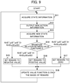
- FIG. 9 is a flowchart for describing an operation of a machine learning unit according to an embodiment of the present disclosure.
- FIG. 10 is a flowchart for describing an operation of an optimization action information output unit of the machine learning unit according to an embodiment of the present disclosure.
- FIG. 11 is an explanatory diagram illustrating a state in which a scale is attached to a machine body.
- FIG. 12 is a block diagram illustrating an example in which a filter is formed by connecting a plurality of filters directly.
- FIG. 13 is a block diagram illustrating another configuration example of a control system.
- FIG. 1 is a block diagram illustrating a motor controller according to an embodiment of the present disclosure, a machine tool, and a control system including an acceleration sensor.
- a control system 10 includes a motor controller 100 , a machine tool 200 controlled by the motor controller 100 , and an acceleration sensor 300 attached to the machine tool 200 .
- the acceleration sensor 300 is an external measuring instrument provided outside the motor controller 100 , and an acceleration measured is measurement information.
- a machine tool is adopted and described as a control target of the motor controller 100 , the control target is not limited to a machine tool but may be a robot, an industrial machine, or the like, for example.
- the motor controller 100 may be provided as a part of a control target such as a machine tool, a robot, or an industrial machine.
- the motor controller 100 includes a command filter 110 , a servo control unit 120 , and a machine learning unit 140 .
- the machine learning unit 140 may be provided outside the motor controller 100 .
- As the command filter 110 a notch filter, a filter that sets an acceleration or deceleration time constant, or an inverse characteristic filter, for example, is used.
- a position command is input to the command filter 110 , and the command filter 110 serves as a position command value shaper that performs shaping of the input position command.
- the position command is generated such that a pulse frequency for changing the velocity of a servo motor 127 is changed by a host controller, an external input device, etc. according to a predetermined machining program.
- the position command serves as a control command.
- the position command is input to the command filter 110 and the machine learning unit 140 .
- the command filter 110 is provided outside the servo control unit 120 (that is, outside a position feedback loop and a velocity feedback loop to be described later)
- the command filter 110 may be provided in a position feedback loop or a velocity feedback loop of the servo control unit 120 .
- the command filter 110 may be connected to an output side of a velocity control unit 125 (to be described later) or an output side of an adder 123 of the servo control unit 120 .
- the command filter 110 is preferably provided outside the position feedback loop or the velocity feedback loop. In FIG.
- the command filter 110 is disposed before a subtractor 121 (to be described later) that calculates a position error, and the output of the command filter 110 is output to the subtractor 121 and a position feedforward unit 130 (to be described later).
- the command filter 110 is preferably an IIR filter (infinite impulse response filter) of the second order or higher.
- Mathematical Expression 1 indicates a transfer function F( ⁇ ,s) of a notch filter as the command filter 110 .
- the parameter ⁇ indicates coefficients ⁇ , ⁇ , and R.
- the coefficients ⁇ , ⁇ , and R serve as first parameters.
- the coefficient R in Mathematical Expression 1 is an attenuation coefficient, the coefficient ⁇ is a central angular frequency, and the coefficient ⁇ is a specific bandwidth.
- the servo control unit 120 includes a subtractor 121 , a position control unit 122 , an adder 123 , a subtractor 124 , a velocity control unit 125 , an adder 126 , a servo motor 127 , an integrator 129 , a position feedforward unit 130 , and a velocity feedforward unit 131 .
- the subtractor 121 , the position control unit 122 , the adder 123 , the subtractor 124 , the velocity control unit 125 , the adder 126 , the servo motor 127 , and the integrator 129 form a position feedback loop.
- the subtractor 124 , the velocity control unit 125 , the adder 126 , and the servo motor 127 form a velocity feedback loop.
- a rotary encoder 128 is attached to the servo motor 127 serving as a motor.
- the rotary encoder 128 and the Integrator 129 are detectors, and the integrator 129 outputs the position detection value to the subtractor 121 as feedback position detection value.
- the servo motor 127 is described as a motor that performs rotary motion, the servo motor 127 may be a linear motor that performs linear motion.
- the subtractor 121 calculates a difference between a position command after shaping output from the command filter 110 and a feedback detection position and outputs the difference to the position control unit 122 and the machine learning unit 140 as a position error.
- the position control unit 122 outputs a value obtained by multiplying the position error by a position gain Kp to the adder 123 as a velocity command value.
- the adder 123 adds the velocity command value and an output value (a position feedforward term) of the position feedforward unit 130 and outputs an addition result to the subtractor 124 as a feedforward-controlled velocity command value.
- the subtractor 124 calculates a difference between the output of the adder 123 and the feedback velocity detection value and outputs the difference to the velocity control unit 125 as a velocity error.
- the velocity control unit 125 adds a value obtained by multiplying and integrating the velocity error by an integral gain K1v and a value obtained by multiplying the velocity error by a proportional gain K2v and outputs an addition result to the adder 126 as a torque command value.
- the adder 126 adds the torque command value and an output value (a velocity feedforward term) of the velocity feedforward unit 131 and outputs an addition result to the servo motor 127 as a feedforward-controlled torque command value.
- the integrator 129 outputs the position detection value by integrating the velocity detection value output from the rotary encoder 128 .
- a rotational angular position of the servo motor 127 is detected by the rotary encoder 128 , and a velocity detection value is input to the subtractor 124 as velocity feedback information (velocity FB information).
- the velocity detection value is integrated by the integrator 129 to be a position detection value, and the position detection value is input to the subtractor 121 as feedback position detection value (position FB information).
- the position feedforward unit 130 performs a position feedforward process represented by a transfer function G(s) indicated by Mathematical Expression 2 (indicated as Math. 2 below) with respect to a value obtained by differentiating the position command value output from the command filter 110 and multiplying the same by a constant and outputs a processing result thereof to the adder 123 as a position feedforward term.
- the coefficients a i and b j (m, n ⁇ i, j ⁇ 0, and m and n are natural numbers) in Expression 2 are the coefficients of the transfer function G(s).
- the velocity feedforward unit 131 performs a velocity feedforward process represented by a transfer function H(s) indicated by Expression 3 (indicated as Math. 3 below) with respect to a value obtained by double-differentiating a position command value and multiplying the same by a constant and outputs the processing result to the adder 126 as a velocity feedforward term.
- the coefficients c i and d j (m, n ⁇ i, j ⁇ 0, and m and n are natural numbers) in Expression 3 are the coefficients of the transfer function H(s).
- the coefficients c i and d j serve as second parameters.
- the natural numbers m and n may be the same numbers the natural numbers as m and n in Expression 2 or other numbers.
- FIG. 2 is a diagram illustrating a configuration of a motor, a part of a machine tool, and an acceleration sensor.
- the machine tool 200 includes a machine body 203 including a coupling (an axis coupling) 201 , a ball screw 202 , and two nuts 203 a and 203 b threaded to the ball screw 202 , connected to a rotation axis of the servo motor 127 . With rotation of the servo motor 127 , the two nuts 203 a and 203 b threaded to the ball screw 202 move in an axial direction of the ball screw 202 whereby the machine body 203 moves.
- the motor controller 100 illustrated in FIG. 1 is provided in the X-axis direction and the Y-axis direction, respectively.
- the motor controller 100 is provided in the respective axial directions.
- the acceleration sensor 300 is provided outside the servo control unit 120 , and in this example, is attached to a machine end of the machine body 203 .
- the acceleration sensor 300 is preferably attached to a machine end near a machining point.
- the acceleration sensor 300 serves as an external measuring instrument.
- Mono-axial, bi-axial, and tri-axial acceleration sensors are known as an acceleration sensor, and these acceleration sensors can be selected as necessary.
- a bi-axial acceleration sensor is used when the machine body 203 is moved in the X-axis direction and the Y-axis direction
- a tri-axial acceleration sensor is used when the machine body 203 is moved in the X-axis direction, the Y-axis direction, and the Z-axis direction.
- the acceleration sensor 300 is preferably provided in a place near a machining point.
- the acceleration sensor 300 measures an acceleration of the machine body 203 and outputs the measured acceleration to the machine learning unit 140 .
- machine learning may be performed before shipping to adjust the coefficients of the command filter 110 and the acceleration sensor 300 may be detached from the machine body 203 after the coefficients of the command filter 110 are adjusted.
- the acceleration sensor 300 may be detached after relearning is performed.
- the acceleration output from the acceleration sensor 300 may be used for feedback control of the servo control unit 120
- the acceleration sensor 300 can be detached unless the acceleration is used for feedback control. In this case, it is possible to reduce the cost of the machine tool 200 and improve reliability.
- the machine learning unit 140 executes a predetermined machining program (hereinafter also referred to as a “learning machining program”) and performs machine learning (hereinafter referred to as learning) on the coefficients ⁇ , ⁇ , and R of the transfer function of the command filter 110 and the coefficients c i and d j of the transfer function of the velocity feedforward unit 131 using the position command, the position error, and the acceleration measurement value from the acceleration sensor 300 .
- the machine learning unit 140 serves as a machine learning device. Although the learning of the machine learning unit 140 is performed before shipping, relearning may be performed after shipping.
- the motor controller 100 drives the servo motor 127 with the aid of the learning machining program and moves the machine body 203 in a state in which a workpiece is not mounted.
- a moving trajectory of an arbitrary point of the machine body 203 moved in the X-axis direction and the Y-axis direction is a circle, a rectangle, an octagon, or a shape in which the corners of an octagon are alternately replaced with arcs.
- FIGS. 3 to 6 are diagrams for describing an operation of a motor when a moving trajectory of a machine body is a circle, a rectangle, an octagon, or a shape in which the corners of an octagon are alternately replaced with arcs. In FIGS. 3 to 6 , it is assumed that the machine body 203 moves in a clockwise direction in the X-axis direction and the Y-axis direction.
- the rotation velocity of the servo motor that moves the machine body 203 in the Y-axis direction gradually decreases at the position A 1 illustrated in FIG. 3 as it approaches the position A 1 and gradually increases after passing through the position A 1 with the rotation direction reversed at the position A 1 .
- the machine body 203 moves to be linearly reversed in the Y-axis direction with the position A 1 interposed therebetween.
- the servo motor that moves the machine body 203 in the X-axis direction rotates at the same velocity as the velocity before and after the position A 1 , and the machine body 203 moves at the same velocity as the velocity before and after the position A 1 in the X-axis direction.
- the respective servo motors are controlled so that the operation of the servo motor that moves the machine body 203 in the X-axis direction and the operation of the servo motor that moves the machine body 203 in the Y-axis direction are reversed.
- the respective servo motors are controlled so that the operation of the servo motor that moves the machine body 203 in the X-axis direction and the operation of the servo motor that moves the machine body 203 in the Y-axis direction are reversed.
- the rotation velocity of the motor that moves the machine body in the Y-axis direction decreases at the corner position C 1 , and the rotation velocity of the motor that moves the machine body 203 in the X-axis direction increases.
- the rotation direction of the motor that moves the machine body 203 in the Y-axis direction is reversed, and the machine body 203 moves to be linearly reversed in the Y-axis direction.
- the motor that moves the machine body 203 in the X-axis direction rotates at a constant velocity in the same rotation direction from the position C 1 to the position C 2 and from the position C 2 to the position C 3 .
- the rotation velocity of the motor that moves the machine body 203 in the Y-axis direction increases, and the rotation velocity of the motor that moves the machine body 203 in the X-axis direction decreases.
- the rotation direction of the motor that moves the machine body 203 in the X-axis direction is reversed and the machine body 203 moves to be linearly reversed in the X-axis direction.
- the motor that moves the machine body 203 in the Y-axis direction rotates at a constant velocity in the same rotation direction from the position C 3 to the position C 4 and from the position C 4 to the next corner position.
- the moving trajectory of the machine body 203 is a shape in which the corners of the octagon are alternately replaced with arcs, as illustrated in FIG. 6
- the rotation velocity of the motor that moves the machine body 203 in the Y-axis direction decreases and the rotation velocity of the motor that moves the machine body 203 in the X-axis direction increases.
- the rotation direction of the motor that moves the machine body 203 in the Y-axis direction is reversed and the machine body 203 moves to be linearly reversed in the Y-axis direction.
- the motor that moves the machine body 203 in the X-axis direction rotates at a constant velocity in the same rotation direction from the position D 1 to the position D 3 .
- the rotation velocity of the motor that moves the machine body 203 in the Y-axis direction gradually decreases as it advances toward the position D 2 so that a moving trajectory of a circular arc is formed before and after the position D 2 and the rotation velocity gradually increases after passing through the position D 2 with the rotation stopped at the position D 2 .
- the rotation velocity of the motor that moves the machine body 203 in the Y-axis direction increases, and the rotation velocity of the motor that moves the machine body 203 in the X-axis direction decreases.
- the rotation direction of the motor that moves the machine body 203 in the X-axis direction is reversed and the machine body 203 moves to be linearly reversed in the X-axis direction.
- the motor that moves the machine body 203 in the Y-axis direction rotates at a constant velocity in the same rotation direction from the position D 3 to the position D 4 and from the position D 4 to the next corner position.
- the rotation velocity of the motor that moves the machine body 203 in the X-axis direction gradually decreases as it advances toward the position D 4 so that a moving trajectory of a circular arc is formed before and after the position D 4 and the rotation velocity gradually increases after passing through the position D 4 with the rotation stopped at the position D 4 .
- vibration generated when the rotation direction of the X-axis direction or the Y-axis direction is reversed at the positions A 1 and A 2 , the positions B 1 and B 2 , the positions C 2 and C 4 , and the positions D 2 and D 4 of the moving trajectory designated by the learning machining program can be measured using the acceleration sensor 300 .
- vibration generated when the rotation velocity is changed during linear control in which the rotation direction is not reversed at the positions C 1 and C 3 and the positions D 1 and D 3 can be measured using the acceleration sensor 300 .
- the machine learning unit 140 will be described in further detail.
- the learning performed by the machine learning unit 140 is not particularly limited to reinforcement learning, but the present invention can be also applied to a case in which the machine learning unit 140 performs supervised learning, for example.
- An agent corresponding to the machine learning unit 140 in the present embodiment observes an environment state and selects a certain action. Then, the environment changes on the basis of the action. A certain reward is given according to the environmental change, and the agent learns selection (decision) for a better action. While supervised learning presents a complete correct answer, the reward in the reinforcement learning often presents a fragmental value based on change in a portion of the environment. Therefore, the agent learns to select an action so that the total of rewards obtained in the future is maximized.
- the reinforcement learning learns a method of learning a suitable action on the basis of the mutual effect of an action on the environment (that is, an action for maximizing the reward to be obtained in the future) by learning an action.
- an action that affects the future for example, an action of selecting action information for suppressing vibration of a machine end, is obtained.
- Q-learning which is a method of learning a value function Q(S,A) of selecting an action A under a certain state S of the environment will be described as an example.
- An object of the Q-learning is to select an action A having the highest value function Q(S,A) as an optimal action among actions A that can be taken in a certain state S.
- the agent learns the correct value Q(S,A) by selecting various actions A under a certain state S and making a better selection of action based on rewards given for the selected actions A.
- E[ ] indicates an expected value
- t indicates time
- ⁇ is a parameter called a discount factor to be described later
- r t is a reward at time t
- ⁇ is the sum at time t.
- the expected value is an expected value when the state was changed according to an optimal action.
- reinforcement learning is performed while searching for an optimal action by performing various actions.
- An updating expression of such a value Q(S,A) can be represented by Expression 4 below (indicated as Math. 4 below).
- S t indicates a state of the environment at time t
- a t indicates an action at time t.
- the state changes to S t+1 .
- r t+1 indicates a reward obtained by the change in the state.
- a term with max is a multiplication of the Q value by ⁇ when an action A having the highest Q value known at that moment is selected under the state S t+1 .
- ⁇ is a parameter of 0 ⁇ 1 and is called a discount rate.
- ⁇ is a learning coefficient and is in the range of 0 ⁇ 1.
- Expression 3 indicates a method of updating a value Q(S t ,A t ) of an action A t in a state S t based on a reward r t+1 that was offered in return when the action A t was performed.
- This updating expression indicates that if the value max a Q(S t+1 ,A) of the best action in the next state S t+1 associated with an action At is larger than the value Q(S t ,A t ) of an action A t in the state S t , Q(S t ,A t ) is increased, and if otherwise, Q(S t ,A t ) is decreased.
- the value of a certain action in a certain state approaches the value of the best action in the next state associated with the action.
- this difference differs depending on the discount rate ⁇ and the reward r t+1
- the value of the best action in a certain state basically propagates to the value of an action in a state previous to that state.
- Q-learning may use an existing technique called a Deep Q-Network (DQN).
- DQN Deep Q-Network
- the value of the value Q(S,A) is calculated by constructing a value function Q using an appropriate neural network and approximating the value function Q with the appropriate neural network by adjusting the parameters of the neural network.
- DQN it is possible to shorten the time required for convergence of Q-learning.
- the details of DQN are disclosed in the Non-Patent Document below, for example.
- the machine learning unit 140 performs the above-described Q-learning. Specifically, the machine learning unit 140 learns a value Q of selecting an action A of adjusting the values of the coefficients ⁇ , ⁇ , and R of the transfer function of the command filter 110 and the coefficients c i and d j of the velocity feedforward unit 131 associated with a state S, wherein the state S includes the values of the coefficients ⁇ , ⁇ , and R of the transfer function of the command filter 110 , the coefficients c i and d j of the velocity feedforward unit 131 , the measured acceleration from the acceleration sensor 300 acquired by executing the learning machining program, the position command, and the position error.
- the machine learning unit 140 observes the state information S including the measured acceleration from the acceleration sensor 300 , the position command, and the position error by executing one or a plurality of learning machining programs described above on the basis of the coefficients ⁇ , ⁇ , and R of the transfer function of the command filter 110 and the coefficients c i and d j of the transfer function of the velocity feedforward unit 131 to determine the action A.
- the machine learning unit 140 receives a reward whenever the action A is executed.
- the machine learning unit 140 searches in trial-and-error manner for the optimal action A so that the total of the reward over the course of the future is maximized.
- the machine learning unit 140 can select an optimal action A (that is, the optimal coefficients ⁇ , ⁇ , and R of the transfer function of the command filter 110 and the optimal coefficients c i and d j of the transfer function of the velocity feedforward unit 131 ) with respect to the state S including the measured acceleration from the acceleration sensor 300 acquired by executing the learning machining program, the position command, and the position error on the basis of the coefficients ⁇ , ⁇ , and R of the transfer function of the command filter 110 and the coefficients c i and d j of the transfer function of the velocity feedforward unit 131 .
- an optimal action A that is, the optimal coefficients ⁇ , ⁇ , and R of the transfer function of the command filter 110 and the optimal coefficients c i and d j of the transfer function of the velocity feedforward unit 131 .
- the machine learning unit 140 can select such an action A (that is, the coefficients ⁇ , ⁇ , and R of the transfer function of the command filter 110 and the coefficients c i and d j of the transfer function of the velocity feedforward unit 131 ) that minimizes the vibration of a machine end generated when a learning machining program is executed by selecting such an action A that maximizes the value of Q among the actions A applied to the coefficients ⁇ , ⁇ , and R of the transfer function of the filter 110 and the coefficients c i and d j of the transfer function of the velocity feedforward unit 131 associated with a certain state S on the basis of the value function Q learned by the machine learning unit 140 .
- an action A that is, the coefficients ⁇ , ⁇ , and R of the transfer function of the command filter 110 and the coefficients c i and d j of the transfer function of the velocity feedforward unit 131
- FIG. 7 is a block diagram illustrating the machine learning unit 140 according to an embodiment of the present disclosure.
- the machine learning unit 140 includes a state information acquisition unit 141 , a learning unit 142 , an action information output unit 143 , a value function storage unit 144 , and an optimization action information output unit 145 .
- the learning unit 142 includes a reward output unit 1421 , a value function updating unit 1422 , and an action information generation unit 1423 .
- the state information acquisition unit 141 acquires the state S including the measured acceleration from the acceleration sensor 300 acquired by executing the learning machining program, the position command, and the position error on the basis of the coefficients ⁇ , ⁇ , and R of the transfer function of the command filter 110 and the coefficients c i and d j of the transfer function of the velocity feedforward unit 131 .
- the state information S corresponds to a state S of the environment in the Q-learning.
- the state information acquisition unit 141 outputs the acquired state information S to the learning unit 142 .
- the coefficients ⁇ , ⁇ , and R of the transfer function of the command filter 110 and the coefficients c i and d j of the transfer function of the velocity feedforward unit 131 at a time point at which the Q-learning starts initially are generated by a user in advance.
- the initial setting values of the coefficients ⁇ , ⁇ , and R of the transfer function of the command filter 110 and the coefficients c i and d j of the transfer function of the velocity feedforward unit 131 calculated by the user are adjusted to optimal values by the reinforcement learning.
- machine learning may be performed using the adjusted values of the coefficients ⁇ , ⁇ , and R and the coefficients c i and d j as the initial values.
- the learning unit 142 is a unit that learns the value Q(S,A) when a certain action A is selected under a certain environment state S.
- the reward output unit 1421 is a unit that calculates a reward when the action A is selected under a certain state S.
- a measured acceleration which is a state variable of the state S will be denoted by y(S)
- a position command which is a state variable associated with the state information S will be denoted by r(S)
- a position error which is a state variable associated with the state information S will be denoted by e(S).
- a measured acceleration which is a state variable associated with state information S′ changed from the state S due to the action information A (compensations of the coefficients ⁇ , ⁇ , and R of the transfer function of the command filter 110 and the coefficients c i and d j of the transfer function of the velocity feedforward unit 131 )
- y(S′) a measured acceleration which is a state variable associated with state information S′ changed from the state S due to the action information A (compensations of the coefficients ⁇ , ⁇ , and R of the transfer function of the command filter 110 and the coefficients c i and d j of the transfer function of the velocity feedforward unit 131 )
- y(S′) a position command which is a state variable associated with the state information S′
- r(S′) a position command which is a state variable associated with the state information S′
- An evaluation function is a function of a measured acceleration, a position command, and a position error
- an evaluation function f(r,y,e) represented by Expression 5 (indicated as Math. 5 below) can be used.
- Expression 5 indicates that the evaluation function f(r,y,e) is the sum of an integral sum (integration) of a square of an acceleration error (a difference between a double differentiation of the position command r and the measured acceleration y) after acceleration and deceleration and the sum (integration) of a double differentiation of a position error.
- the measured acceleration y is the measured acceleration after acceleration and deceleration.
- the coefficients ⁇ and ⁇ are predetermined constants.
- the acceleration error after acceleration and deceleration is a value extracted in a region (a region indicated by a dot line in FIG. 8 ) in which acceleration and deceleration ends and a machine end acceleration is in a settled state.
- FIG. 8 is a characteristic diagram showing the command acceleration and the mechanical end acceleration.
- a command acceleration indicated by a solid line is obtained by double-differentiating a position command, and a machine end acceleration indicated by a dot line is a measured acceleration of the acceleration sensor 300 .
- Expression 6 and Expression 7 (indicated as Math. 6 and Math. 7 below) illustrated below can be used as the evaluation function f(r,y,e).
- the coefficients ⁇ , ⁇ , ⁇ are predetermined constants.
- the first term of Expressions 5 to 8 may use a time integration of an absolute value of an expression (d 2 r/dt 2 ⁇ y) and a time integration of time (t)-weighted absolute value of the expression (d 2 r/dt 2 ⁇ y).
- the reward output unit 1421 sets a reward value to a negative value.
- the reward output unit 1421 sets a reward value to a positive value.
- the reward output unit 1421 sets the value of the reward to zero.
- the negative value when the evaluation function f(r(S′),y(S′),e(S′)) of the state S′ after execution of the action A is larger than the evaluation function f(r(S),y(S),e(S)) of the previous state S may increase according to a proportion. That is, the negative value may increase according to the degree of increase in the evaluation function f(r(S′),y(S′),e(S′)).
- the positive value when the evaluation function f(r(S′),y(S′),e(S′)) of the state S′ after execution of the action A is smaller than the evaluation function f(r(S),y(S),e(S)) of the previous state S may increase according to a proportion. That is, the positive value may increase according to the degree of decrease in the evaluation function f(r(S′),y(S′),e(S′)).
- the value function updating unit 1422 updates the value function Q stored in the value function storage unit 144 by performing Q-learning on the basis of the state S, the action A, the state S′ when the action A was applied to the state S, and the value of the reward calculated in this manner.
- the update of the value function Q may be performed by online learning, batch learning, or mini-batch learning.
- Online learning is a learning method of applying a certain action A to a present state S and updating the value function Q immediately whenever the present state S transitions to a new state S′.
- batch learning is a learning method of applying a certain action A to a present state S and repeated attaining transition from the state S to a new state S′, collecting learning data, and updating the value function Q using all the collected learning data.
- mini-batch learning is a learning method which is intermediate between online learning and batch learning and involves updating the value function Q whenever a certain amount of learning data is collected.
- the action information generation unit 1423 selects the action A in the process of Q-learning with respect to the present state S.
- the action information generation unit 1423 generates action information A and outputs the generated action information A to the action information output unit 143 in order to perform an operation (corresponding to the action A of Q-learning) of correcting the coefficients ⁇ , ⁇ , and R of the transfer function of the command filter 110 and the coefficients c i and d j of the velocity feedforward unit 131 in the process of Q-learning.
- the action information generation unit 1423 adds or subtracts the coefficients ⁇ , ⁇ , and R of the transfer function of the command filter 110 and the coefficients c i and d j of the velocity feedforward unit 131 included in the action A incrementally with respect to the coefficients ⁇ , ⁇ , and R of the transfer function of the command filter 110 and the coefficients c i and d j of the velocity feedforward unit 131 included in the state S, for example.
- the action information generation unit 1423 may select a policy of selecting such an action A′ that further decreases the value of the evaluation function f such as incrementally increasing or decreasing the coefficients ⁇ , ⁇ , and R of the transfer function of the command filter 110 and the coefficients c i and d j of the velocity feedforward unit 131 similarly to the previous action as the next action A′.
- the action information generation unit 1423 may select a policy of selecting such an action A′ that decreases the evaluation function f to be smaller than the previous value such as incrementally decreasing or increasing the coefficients ⁇ , ⁇ , and R of the transfer function of the command filter 110 and the coefficients c i and d j of the velocity feedforward unit 131 contrarily to the previous action as the next action A′, for example.
- the action information generation unit 1423 may select a policy of selecting the action A′ according to a known method such as a greedy method of selecting an action A′ having the highest value function Q(S,A) among the values of presently estimated actions A and an ⁇ -greedy method of randomly selecting an action A′ with a certain small probability e and selecting an action A′ having the highest value function Q(S,A) in other cases.
- a known method such as a greedy method of selecting an action A′ having the highest value function Q(S,A) among the values of presently estimated actions A and an ⁇ -greedy method of randomly selecting an action A′ with a certain small probability e and selecting an action A′ having the highest value function Q(S,A) in other cases.
- the action information output unit 143 is a unit that the action information A output from the learning unit 142 to the command filter 110 .
- the command filter 110 finely adjusts the present state S (that is, the coefficients ⁇ , ⁇ , and R and the coefficients c i and d j set presently) on the basis of the action information to thereby transition to the next state S′ (that is, the corrected coefficients of the command filter 110 and the corrected coefficients c i and d j of the velocity feedforward unit 131 ).
- the value function storage unit 144 is a storage device that stores the value function Q.
- the value function Q may be stored as a table (hereinafter referred to as an action value table) for each state S and each action A, for example.
- the value function Q stored in the value function storage unit 144 is updated by the value function updating unit 1422 .
- the value function Q stored in the value function storage unit 144 may be shared with other machine learning units 140 .
- the value function Q is shared by a plurality of machine learning units 140 , since reinforcement learning can be performed in a manner of being distributed to the respective machine learning units 140 , it is possible to improve the reinforcement learning efficiency.
- the optimization action information output unit 145 generates the action information A (hereinafter referred to as “optimization action information”) for causing the command filter 110 and the velocity feedforward unit 131 to perform an operation of maximizing the value function Q(S,A) on the basis of the value function Q updated by the value function updating unit 1422 performing the Q-learning. More specifically, the optimization action information output unit 145 acquires the value function Q stored in the value function storage unit 144 . As described above, the value function Q is updated by the value function updating unit 1422 performing the Q-learning. The optimization action information output unit 145 generates the action information on the basis of the value function Q and outputs the generated action information to the command filter 110 .
- optimization action information (hereinafter referred to as “optimization action information”) for causing the command filter 110 and the velocity feedforward unit 131 to perform an operation of maximizing the value function Q(S,A) on the basis of the value function Q updated by the value function updating unit 1422 performing the Q-learning. More specifically, the optimization action information output unit
- the optimization action information includes information that corrects the coefficients ⁇ , ⁇ , and R of the transfer function of the command filter 110 and the coefficients c i and d j of the transfer function of the velocity feedforward unit 131 similarly to the action information that the action information output unit 143 outputs in the process of Q-learning.
- the coefficients ⁇ , ⁇ , and R of the transfer function and the coefficients c i and d j of the transfer function are corrected on the basis of the action information.
- the machine learning unit 140 can optimize the coefficients ⁇ , ⁇ , and R of the transfer function of the command filter 110 and the coefficients c i and d j of the transfer function of the velocity feedforward unit 131 and operate so that vibration of a machine end is suppressed. As described above, it is possible to simplify adjustment of the parameters of the command filter 110 and the parameters of the velocity feedforward unit 131 using the machine learning unit 140 according to the present embodiment.
- the motor controller 100 includes an arithmetic processing unit such as a central processing unit (CPU).
- the motor controller 100 further includes an auxiliary storage device such as a hard disk drive (HDD) for storing various control programs such as application software or an operating system (OS) and a main storage device such as a random access memory (RAM) for storing data temporarily required when the arithmetic processing device executes a program.
- arithmetic processing unit such as a central processing unit (CPU).
- the motor controller 100 further includes an auxiliary storage device such as a hard disk drive (HDD) for storing various control programs such as application software or an operating system (OS) and a main storage device such as a random access memory (RAM) for storing data temporarily required when the arithmetic processing device executes a program.
- HDD hard disk drive
- RAM random access memory
- the arithmetic processing device reads an application and an OS from the auxiliary storage device, and develops the read application software and OS in the main storage device to perform arithmetic processing on the basis of the read application software and OS.
- the arithmetic processing device also controls various types of hardware provided in each device based on the arithmetic result. In this way, the functional blocks of the present embodiment are realized. That is, the present embodiment can be realized by cooperation of hardware and software.
- GPUs graphics processing units
- GPGPUs general-purpose computing on graphics processing units
- a computer cluster may be built using a plurality of computers equipped with such GPUs, and the plurality of computers included in the computer cluster may perform parallel processing.
- step S 11 the state information acquisition unit 141 acquires the state information S from the motor controller 100 .
- the acquired state information S is output to the value function updating unit 1422 and the action information generation unit 1423 .
- the state information S is information corresponding to the state of Q-learning and includes the coefficients ⁇ , ⁇ , and R of the transfer function of the command filter 110 and the coefficients c i and d j of the transfer function of the velocity feedforward unit 131 at the time point of step S 11 .
- a position command r(S), a position error e(S), and a measured acceleration y(S) corresponding to a predetermined feed rate and the shape of a moving trajectory when the coefficients of the transfer function of the command filter 110 and the coefficients of the transfer function of the velocity feedforward unit 131 are initial values are acquired.
- the position command r(S 0 ) and the position error e(S 0 ) in the state S 0 at a time point at which Q-learning starts initially and the measured acceleration y(S 0 ) from the acceleration sensor 300 are obtained by operating the motor controller 100 according to the learning machining program.
- the position command input to the motor controller 100 is a position command corresponding to a predetermined moving trajectory designated by the machining program (for example, the octagonal moving trajectory illustrated in FIGS. 5 and 6 ).
- the position command is input to the command filter 110 and the machine learning unit 140 .
- the initial values of the coefficients ⁇ , ⁇ , and R of the transfer function of the command filter 110 and the coefficients c i and d j of the transfer function of the velocity feedforward unit 131 are generated by a user in advance, and the initial values of the coefficients ⁇ , ⁇ , and R and the coefficients c i and d j are transmitted to the machine learning unit 140 .
- the acceleration sensor 300 outputs the measured acceleration y(S 0 ) at the respective positions such as the positions C 1 to C 4 and the positions D 1 to D 4 of the moving trajectory to the machine learning unit 140 .
- the machine learning unit 140 may extract the position command r(S 0 ), the position error e(S 0 ), and the measured acceleration y(S 0 ) at the respective positions such as the positions C 1 to C 4 and the positions D 1 to D 4 of the moving trajectory.
- step S 12 the action information generation unit 1423 generates new action information A and outputs the generated new action information A to the command filter 110 via the action information output unit 143 .
- the action information generation unit 1423 outputs the new action information A on the basis of the above-described policy.
- the motor controller 100 having received the action information A drives a machine tool including the servo motor 127 according to the state S′ obtained by correcting the coefficients ⁇ , ⁇ , and R of the transfer function of the command filter 110 and the coefficients c i and d j of the transfer function of the velocity feedforward unit 131 associated with the present state S on the basis of the received action information.
- the action information corresponds to the action A in Q-learning.
- step S 13 the state information acquisition unit 141 acquires the position command r(S′), the position error e(S′), the measured acceleration y(S′) from the acceleration sensor 300 , the coefficients ⁇ , ⁇ , and R of the transfer function from the command filter 110 , and the coefficients c i and d j of the velocity feedforward unit 131 in the new state S′.
- the state information acquisition unit 141 acquires the position command r(S′), the position error e(S′), and the measured acceleration y(S′) corresponding to the octagonal moving trajectory (specifically, the positions such as the positions C 1 to C 4 and the positions D 1 to D 4 of the moving trajectory) and the coefficients ⁇ , ⁇ , and R and the coefficients c i and d j in the state S′.
- the acquired state information is output to the reward output unit 1421 .
- step S 14 the reward output unit 1421 determines a magnitude relation between the evaluation function f(r(S′),y(S′),e(S′)) in the state S′ and the evaluation function f(r(S),y(S),e(S)) in the state S and sets the reward to a negative value in step S 15 when f(r(S′),y(S′),e(S′))>f(r(S),y(S),e(S)).
- the reward output unit 1421 sets the reward to a positive value in step S 16 .
- the reward output unit 1421 sets the reward to zero in step S 17 .
- the reward output unit 1421 may apply a weighting to the negative and positive reward values.
- the state S transitions to the state S 0 at a time point at which Q-learning starts.
- the value function updating unit 1422 updates the value function Q stored in the value function storage unit 144 on the basis of the value of the reward calculated in any one of the steps in step S 18 .
- the flow returns to step S 11 again, and the above-described process is repeated, whereby the value function Q settles to an appropriate value.
- the process may end on condition that the above-described process is repeated a predetermined number of times or for a predetermined period.
- online updating is exemplified in step S 18 , batch updating or mini-batch updating may be performed instead of the online updating.
- step S 21 the optimization action information output unit 145 acquires the value function Q stored in the value function storage unit 144 .
- the value function Q is updated by the value function updating unit 1422 performing the Q-learning.
- step S 22 the optimization action information output unit 145 generates the optimization action information on the basis of the value function Q and outputs the generated optimization action information to the command filter 110 .
- the optimization action information on the basis of the value function Q obtained by the learning of the machine learning unit 140 , simplify adjustment of the coefficients ⁇ , ⁇ , and R of the transfer function of the command filter 110 and the coefficients c i and d j of the transfer function of the velocity feedforward unit 131 set presently on the basis of the optimization action information, suppress a trajectory error and vibration of a machine end, and improve the quality of a machining surface of a work. Since the external measuring instrument is disposed outside the motor controller, it is possible to detach the external measuring instrument after machine learning is performed and to reduce the cost and improve reliability.
- the servo control unit of the motor controller described above and the components included in the machine learning unit may be realized by hardware, software or a combination thereof.
- the servo control method performed by cooperation of the components included in the motor controller described above also may be realized by hardware, software, or a combination thereof.
- being realized by software means being realized when a computer reads and executes a program.
- the programs can be stored on any of various types of non-transitory computer readable media and be provided to a computer.
- the non-transitory computer readable media include various types of tangible storage media. Examples of the non-transitory computer readable media include a magnetic recording medium (for example a flexible disk and a hard disk drive), a magneto-optical recording medium (for example a magneto-optical disk), a CD-ROM (Read Only Memory), a CD-R, a CD-R/W, a semiconductor memory (for example a mask ROM, a PROM (Programmable ROM), an EPROM (Erasable PROM), a flash ROM, and a RAM (Random Access Memory)).
- the programs may be supplied to a computer via various types of transitory computer readable media.
- the machine learning unit 140 may learn and optimize one of the coefficients ⁇ , ⁇ , and R and the coefficients c i and d j and then optimize learning of the other coefficients.
- the coefficients a i and b j of the transfer function of the position feedforward unit 130 may be learned together.
- FIG. 11 is an explanatory diagram illustrating a state in which a scale is attached to the machine body 203 .
- a scale 301 detects the position of the machine body 203 and outputs position information to the machine learning unit 140 .
- the machine learning unit 140 can obtain acceleration information by double-differentiating the obtained position information.
- FIG. 12 is a block diagram illustrating an example in which a plurality of filters are connected in series to form a filter.
- the command filter 110 is formed by connecting m command filters 110 - 1 to 110 - m in series.
- Optimal values for attenuating resonance points are calculated sequentially by machine learning with respect to the coefficients ⁇ , ⁇ , and R of the m command filters 110 - 1 to 110 - m.
- the control system may have the following configuration other than the configuration illustrated in FIG. 1 .
- FIG. 13 is a block diagram illustrating another configuration example of the control system.
- a difference between a control system 10 A illustrated in FIG. 13 and the control system 10 illustrated in FIG. 1 is that n (n is a natural number of 2 or more) motor controllers 100 A- 1 to 100 A-n and n machine tools 200 - 1 to 200 - n having acceleration sensors 300 - 1 to 300 - n attached thereto are connected to machine learning devices 140 A- 1 to 140 A-n via a network 400 .
- the motor controllers 100 A- 1 to 100 A-n have the same configuration as the motor controller 100 illustrated in FIG. 1 except that the motor controller does not include a machine learning unit.
- the machine learning devices 140 A- 1 to 140 A-n have the same configuration as the machine learning unit 140 illustrated in FIG. 7 .
- the motor controller 100 A- 1 , the acceleration sensor 300 - 1 and the machine learning device 140 A- 1 are communicably connected as a one-to-one correlation.
- the motor controllers 100 A- 2 to 100 A-n, the acceleration sensors 300 - 1 to 300 - n , and the machine learning devices 140 A- 2 to 140 A-n are connected similarly to the motor controller 100 A- 1 , the machine tool 200 - 1 , and the machine learning device 140 A- 1 .
- n pairs of the motor controllers 100 A- 1 to 100 A-n, the acceleration sensors 300 - 1 to 300 - n , and the machine learning devices 140 A- 1 to 140 A-n are connected via the network 400 in FIG.
- the n pairs of the motor controllers 100 A- 1 to 100 A-n, the acceleration sensors 300 - 1 to 300 - n , and the machine learning devices 140 A- 1 to 140 A-n may be connected directly such that the motor controller, the machine tool, and the machine learning device of each pair are connected directly by a connection interface.
- a plurality of n pairs of the machine tools 200 - 1 to 200 - n to which the motor controllers 100 A- 1 to 100 A-n and the acceleration sensors 300 - 1 to 300 - n are attached and the machine learning devices 140 A- 1 to 140 A-n may be provided in the same plant, for example, and may be provided in different plants.
- the network 400 is a local area network (LAN) constructed in a plant, the Internet, a public telephone network, a direct connection via a connection interface, or a combination thereof, for example.
- LAN local area network
- a specific communication scheme of the network 400 , whether the network uses a cable connection or a wireless connection, and the like are not particularly limited.
- one machine learning device may be communicably connected to a plurality of motor controllers and a plurality of acceleration sensors via the network 400 and the machine learning of the respective motor controllers and the respective machine tools may be performed.
- a distributed processing system may be adopted, in which respective functions of one machine learning device are distributed to a plurality of servers as appropriate.
- the functions of one machine learning device may be realized by utilizing a virtual server function or the like on a cloud.
- the machine learning devices 140 A- 1 to 140 A-n may be configured to share learning results in the machine learning devices 140 A- 1 to 140 A-n. By doing so, a more optimal model can be constructed.
- the machine learning device, the control system, and the machine learning method according to the present disclosure can take various embodiments having the following configuration including the above-described embodiment.
- An aspect of the present disclosure is a machine learning device 140 that performs machine learning of optimizing first coefficients of a filter 110 provided in a motor controller 100 that controls a motor 127 and second coefficients of a velocity feedforward unit 131 on the basis of an evaluation function which is a function of measurement information after acceleration and deceleration by an external measuring instrument provided outside the motor controller 100 , a position command input to the motor controller 100 , and a position error which is a difference between the position command value and feedback position detection value from a detector of the servo control unit 120 .
- this machine learning device 140 it is possible to suppress vibration of a machine end and an error of a moving trajectory by machine-learning the first coefficients that determine the characteristics of the filter 110 and the second coefficients of the velocity feedforward unit 131 . Moreover, since the external measuring instrument is disposed outside the motor controller 100 , it is possible to detach the external measuring instrument after machine learning is performed and to reduce the cost and improve reliability.
- the measurement information of the external measuring instrument includes at least one of a position, a velocity, and an acceleration.
- the servo control unit 120 includes at least one of a position feedback loop and a velocity feedback loop, and the filter 110 is provided outside the position feedback loop or the velocity feedback loop. According to this machine learning device 140 , it is possible to suppress vibration outside a control loop (a position feedback loop or a velocity feedback loop) of the servo control unit 120 .
- the motor control unit 120 has a feedback loop and the measurement information of the external measuring instrument is not used for feedback control of the feedback loop. According to this machine learning device 140 , the external measuring instrument can be detached. As a result, it is possible to reduce the cost of the machine tool and the like and improve reliability.
- the external measuring instrument is detached after adjustment of the filter 110 by machine learning.
- the external measuring instrument can be detached after adjustment of the filter 110 is performed, and as a result, it is possible to reduce the cost of the machine tool and the like and improve reliability.
- the filter 110 is an IIR filter of the second order or higher. According to this machine learning device 140 , since the number of taps can be decreased as compared to FIR filters, it is possible to obtain a faster filter 110 .
- the machine learning device 140 further including: a state information acquisition unit 141 that acquires state information including the measurement information, the position command, the position error, the first coefficients of the filter 110 , and the second coefficients of the velocity feedforward unit 131 ;
- an action information output unit 143 that outputs action information including adjustment information of the first and second coefficients included in the state information to the filter 110 and the velocity feedforward unit 131 ;
- a reward output unit 1421 that outputs a reward value of reinforcement learning using a value function which is a function of the measurement information, the position command, and the position error;
- a value function updating unit 144 that updates an action value function on the basis of the reward value output by the reward output unit, the state information, and the action information.
- the machine learning device 140 further including: an optimization action information output unit 145 that outputs adjustment information of the first and second coefficients on the basis of the value function updated by the value function updating unit 144 .
- a control system 10 including: a motor controller 100 that includes the machine learning device 140 according to any one of (1) to (8), a motor 127 , a servo control unit 120 that includes a velocity feedforward unit 131 , and a filter 110 , the motor controller controlling the motor 127 ; and an external measuring instrument provided outside the motor controller 100 .
- a machine learning method of a machine learning device 140 including: acquiring first coefficients of a filter 110 provided in a motor controller 100 that controls a motor 127 , second coefficients of a velocity feedforward unit 131 , measurement information after acceleration and deceleration by an external measuring instrument provided outside the motor controller 100 , a position command input to the motor controller 100 , and a position error which is a difference between the position command value and feedback position detection value; and performing machine learning of optimizing the first coefficients and the second coefficients on the basis of an evaluation function which is a function of the measurement information, the position command, and the position error.
- this machine learning method it is possible to suppress vibration of a machine end and an error of a moving trajectory by machine-learning the first coefficients that determine the characteristics of the filter 110 and the second coefficients of the velocity feedforward unit 131 . Moreover, since the external measuring instrument is disposed outside the motor controller 100 , it is possible to detach the external measuring instrument after machine learning is performed and to reduce the cost and improve reliability.
Landscapes
- Engineering & Computer Science (AREA)
- General Physics & Mathematics (AREA)
- Automation & Control Theory (AREA)
- Physics & Mathematics (AREA)
- Artificial Intelligence (AREA)
- Manufacturing & Machinery (AREA)
- Human Computer Interaction (AREA)
- Health & Medical Sciences (AREA)
- Computer Vision & Pattern Recognition (AREA)
- Evolutionary Computation (AREA)
- Medical Informatics (AREA)
- Software Systems (AREA)
- Feedback Control In General (AREA)
- Numerical Control (AREA)
- Control Of Electric Motors In General (AREA)
Abstract
Description
The
As illustrated in
Although an integration of a square is performed in each term of Expressions 5 to 8, an absolute value may be integrated or an absolute value may be time (t)-weighted. For example, the first term of Expressions 5 to 8 may use a time integration of an absolute value of an expression (d2r/dt2−y) and a time integration of time (t)-weighted absolute value of the expression (d2r/dt2−y).
- 10, 10A: Control system
- 100, 100A-1 to 100A-n: Motor controller
- 110: Command filter
- 120: Servo control unit
- 121: Subtractor
- 122: Position control unit
- 123: Adder
- 124: Subtractor
- 125: Velocity control unit
- 126: Adder
- 127: Servo motor
- 128: Rotary encoder
- 129: Integrator
- 130: Position feedforward unit
- 131: Velocity feedforward unit
- 140: Machine learning unit
- 140A-1 to 140A-n: Machine learning device
- 141: State information acquisition unit
- 142: Learning unit
- 143: Action information output unit
- 144: Value function storage unit
- 145: Optimization action information output unit
- 200, 200-1 to 200-n: Machine tool
- 300: Acceleration sensor
- 400: Network
Claims (10)
Applications Claiming Priority (3)
| Application Number | Priority Date | Filing Date | Title |
|---|---|---|---|
| JP2019-054837 | 2019-03-22 | ||
| JPJP2019-054837 | 2019-03-22 | ||
| JP2019054837A JP7000371B2 (en) | 2019-03-22 | 2019-03-22 | Machine learning equipment, control systems and machine learning methods |
Publications (2)
| Publication Number | Publication Date |
|---|---|
| US20200301376A1 US20200301376A1 (en) | 2020-09-24 |
| US11243501B2 true US11243501B2 (en) | 2022-02-08 |
Family
ID=72513626
Family Applications (1)
| Application Number | Title | Priority Date | Filing Date |
|---|---|---|---|
| US16/807,804 Active 2040-03-14 US11243501B2 (en) | 2019-03-22 | 2020-03-03 | Machine learning device, control system, and machine learning |
Country Status (4)
| Country | Link |
|---|---|
| US (1) | US11243501B2 (en) |
| JP (1) | JP7000371B2 (en) |
| CN (1) | CN111722530B (en) |
| DE (1) | DE102020203377B4 (en) |
Cited By (1)
| Publication number | Priority date | Publication date | Assignee | Title |
|---|---|---|---|---|
| DE102023205425B4 (en) | 2022-06-13 | 2026-03-19 | Hochschule Heilbronn, Körperschaft des öffentlichen Rechts | Computer-implemented method for creating a feedforward neural network |
Families Citing this family (5)
| Publication number | Priority date | Publication date | Assignee | Title |
|---|---|---|---|---|
| US12399483B2 (en) * | 2019-10-21 | 2025-08-26 | Semiconductor Components Industries, Llc | Systems and methods for system optimization and/or failure detection |
| WO2022065190A1 (en) * | 2020-09-23 | 2022-03-31 | ファナック株式会社 | Control assistance device, control system, and filter adjustment method |
| TW202318120A (en) * | 2021-10-29 | 2023-05-01 | 日商松下知識產權經營股份有限公司 | Control parameter generation method, program, recording medium, and control parameter generating device |
| US20250362647A1 (en) * | 2022-07-01 | 2025-11-27 | Panasonic Intellectual Property Management Co., Ltd. | Control parameter generation method, program, recording medium, and control parameter generation device |
| CN118617183B (en) * | 2024-06-13 | 2025-11-07 | 武汉重型机床集团有限公司 | Active vibration suppression method, system and storage medium based on cutter workpiece system |
Citations (12)
| Publication number | Priority date | Publication date | Assignee | Title |
|---|---|---|---|---|
| JPH0285902A (en) | 1988-09-22 | 1990-03-27 | Mitsubishi Electric Corp | Feedforward controller |
| JPH0484303A (en) | 1990-07-27 | 1992-03-17 | Hitachi Ltd | Servo controller |
| JPH0519858A (en) | 1991-07-15 | 1993-01-29 | Yokogawa Electric Corp | Servo actuator |
| JP2009104439A (en) | 2007-10-24 | 2009-05-14 | Yokogawa Electric Corp | Servo actuator |
| JP2009110492A (en) | 2007-10-09 | 2009-05-21 | Okuma Corp | Position control device |
| US20120296471A1 (en) * | 2011-05-17 | 2012-11-22 | Fanuc Corporation | Robot and spot welding robot with learning control function |
| WO2015111298A1 (en) | 2014-01-23 | 2015-07-30 | 三菱電機株式会社 | Motor control device |
| US20180225113A1 (en) * | 2017-02-06 | 2018-08-09 | Seiko Epson Corporation | Control device, robot, and robot system |
| US20180222048A1 (en) * | 2017-02-06 | 2018-08-09 | Seiko Epson Corporation | Control device, robot, and robot system |
| US20180229364A1 (en) * | 2017-02-15 | 2018-08-16 | Fanuc Corporation | Robot system having learning control function and learning control method |
| WO2018151215A1 (en) | 2017-02-20 | 2018-08-23 | 株式会社安川電機 | Control device and control method |
| US20190227502A1 (en) * | 2018-01-25 | 2019-07-25 | Fanuc Corporation | Machine learning device, servo motor controller, servo motor control system, and machine learning method |
Family Cites Families (2)
| Publication number | Priority date | Publication date | Assignee | Title |
|---|---|---|---|---|
| JP6490127B2 (en) * | 2017-03-15 | 2019-03-27 | ファナック株式会社 | Machine learning device, servo control device, servo control system, and machine learning method |
| JP6538766B2 (en) * | 2017-07-18 | 2019-07-03 | ファナック株式会社 | Machine learning apparatus, servo motor control apparatus, servo motor control system, and machine learning method |
-
2019
- 2019-03-22 JP JP2019054837A patent/JP7000371B2/en active Active
-
2020
- 2020-03-03 US US16/807,804 patent/US11243501B2/en active Active
- 2020-03-17 DE DE102020203377.3A patent/DE102020203377B4/en active Active
- 2020-03-19 CN CN202010196171.1A patent/CN111722530B/en active Active
Patent Citations (12)
| Publication number | Priority date | Publication date | Assignee | Title |
|---|---|---|---|---|
| JPH0285902A (en) | 1988-09-22 | 1990-03-27 | Mitsubishi Electric Corp | Feedforward controller |
| JPH0484303A (en) | 1990-07-27 | 1992-03-17 | Hitachi Ltd | Servo controller |
| JPH0519858A (en) | 1991-07-15 | 1993-01-29 | Yokogawa Electric Corp | Servo actuator |
| JP2009110492A (en) | 2007-10-09 | 2009-05-21 | Okuma Corp | Position control device |
| JP2009104439A (en) | 2007-10-24 | 2009-05-14 | Yokogawa Electric Corp | Servo actuator |
| US20120296471A1 (en) * | 2011-05-17 | 2012-11-22 | Fanuc Corporation | Robot and spot welding robot with learning control function |
| WO2015111298A1 (en) | 2014-01-23 | 2015-07-30 | 三菱電機株式会社 | Motor control device |
| US20180225113A1 (en) * | 2017-02-06 | 2018-08-09 | Seiko Epson Corporation | Control device, robot, and robot system |
| US20180222048A1 (en) * | 2017-02-06 | 2018-08-09 | Seiko Epson Corporation | Control device, robot, and robot system |
| US20180229364A1 (en) * | 2017-02-15 | 2018-08-16 | Fanuc Corporation | Robot system having learning control function and learning control method |
| WO2018151215A1 (en) | 2017-02-20 | 2018-08-23 | 株式会社安川電機 | Control device and control method |
| US20190227502A1 (en) * | 2018-01-25 | 2019-07-25 | Fanuc Corporation | Machine learning device, servo motor controller, servo motor control system, and machine learning method |
Non-Patent Citations (1)
| Title |
|---|
| Notification of Reasons for Refusal dated Apr. 20, 2021 in JP Patent Application No. 2019-054837. |
Cited By (1)
| Publication number | Priority date | Publication date | Assignee | Title |
|---|---|---|---|---|
| DE102023205425B4 (en) | 2022-06-13 | 2026-03-19 | Hochschule Heilbronn, Körperschaft des öffentlichen Rechts | Computer-implemented method for creating a feedforward neural network |
Also Published As
| Publication number | Publication date |
|---|---|
| JP2020154989A (en) | 2020-09-24 |
| US20200301376A1 (en) | 2020-09-24 |
| CN111722530A (en) | 2020-09-29 |
| DE102020203377B4 (en) | 2025-04-24 |
| CN111722530B (en) | 2023-12-15 |
| JP7000371B2 (en) | 2022-01-19 |
| DE102020203377A1 (en) | 2020-11-19 |
Similar Documents
| Publication | Publication Date | Title |
|---|---|---|
| US11243501B2 (en) | Machine learning device, control system, and machine learning | |
| US11029650B2 (en) | Machine learning device, control system, and machine learning method | |
| US10824121B2 (en) | Machine learning device, servo motor controller, servo motor control system, and machine learning method | |
| JP6490127B2 (en) | Machine learning device, servo control device, servo control system, and machine learning method | |
| US11592789B2 (en) | Output device, control device, and method for outputting evaluation functions and machine learning results | |
| US11521119B2 (en) | Machine learning device, control device, and machine learning method | |
| US11087509B2 (en) | Output device, control device, and evaluation function value output method | |
| US11256220B2 (en) | Machine learning device, control device and machine learning method | |
| US20200133226A1 (en) | Output device, control device and method of outputting learning parameter | |
| US11023827B2 (en) | Machine learning device, servo control device, servo control system, and machine learning method for suppressing variation in position error using feedforward control | |
| US11914333B2 (en) | Machine learning device, servo control device, servo control system, and machine learning method | |
| US20200342356A1 (en) | Machine learning device, numerical control system, and machine learning method | |
| US11507885B2 (en) | Machine learning device, control device, and machine learning search range setting method | |
| US11226599B2 (en) | Machine learning system, control device, and machine learning method for optimizing filter coefficients | |
| WO2022030346A1 (en) | Control assistance device, control system, and control assistance method | |
| US10901374B2 (en) | Machine learning device, control device, and machine learning method | |
| US20230103001A1 (en) | Machine learning device, control device, and machine learning method |
Legal Events
| Date | Code | Title | Description |
|---|---|---|---|
| AS | Assignment |
Owner name: FANUC CORPORATION, JAPAN Free format text: ASSIGNMENT OF ASSIGNORS INTEREST;ASSIGNORS:TSUNEKI, RYOUTAROU;IKAI, SATOSHI;REEL/FRAME:051997/0149 Effective date: 20200213 |
|
| FEPP | Fee payment procedure |
Free format text: ENTITY STATUS SET TO UNDISCOUNTED (ORIGINAL EVENT CODE: BIG.); ENTITY STATUS OF PATENT OWNER: LARGE ENTITY |
|
| STPP | Information on status: patent application and granting procedure in general |
Free format text: DOCKETED NEW CASE - READY FOR EXAMINATION |
|
| STPP | Information on status: patent application and granting procedure in general |
Free format text: NON FINAL ACTION MAILED |
|
| STPP | Information on status: patent application and granting procedure in general |
Free format text: RESPONSE TO NON-FINAL OFFICE ACTION ENTERED AND FORWARDED TO EXAMINER |
|
| STPP | Information on status: patent application and granting procedure in general |
Free format text: NOTICE OF ALLOWANCE MAILED -- APPLICATION RECEIVED IN OFFICE OF PUBLICATIONS |
|
| STPP | Information on status: patent application and granting procedure in general |
Free format text: PUBLICATIONS -- ISSUE FEE PAYMENT VERIFIED |
|
| STCF | Information on status: patent grant |
Free format text: PATENTED CASE |
|
| MAFP | Maintenance fee payment |
Free format text: PAYMENT OF MAINTENANCE FEE, 4TH YEAR, LARGE ENTITY (ORIGINAL EVENT CODE: M1551); ENTITY STATUS OF PATENT OWNER: LARGE ENTITY Year of fee payment: 4 |