US11242592B2 - Continuous nitriding treatment furnace and continuous nitriding treatment method - Google Patents
Continuous nitriding treatment furnace and continuous nitriding treatment method Download PDFInfo
- Publication number
- US11242592B2 US11242592B2 US16/324,302 US201716324302A US11242592B2 US 11242592 B2 US11242592 B2 US 11242592B2 US 201716324302 A US201716324302 A US 201716324302A US 11242592 B2 US11242592 B2 US 11242592B2
- Authority
- US
- United States
- Prior art keywords
- nitriding
- zone
- chamber
- continuous
- atmosphere gas
- Prior art date
- Legal status (The legal status is an assumption and is not a legal conclusion. Google has not performed a legal analysis and makes no representation as to the accuracy of the status listed.)
- Active, expires
Links
Images


Classifications
-
- C—CHEMISTRY; METALLURGY
- C23—COATING METALLIC MATERIAL; COATING MATERIAL WITH METALLIC MATERIAL; CHEMICAL SURFACE TREATMENT; DIFFUSION TREATMENT OF METALLIC MATERIAL; COATING BY VACUUM EVAPORATION, BY SPUTTERING, BY ION IMPLANTATION OR BY CHEMICAL VAPOUR DEPOSITION, IN GENERAL; INHIBITING CORROSION OF METALLIC MATERIAL OR INCRUSTATION IN GENERAL
- C23C—COATING METALLIC MATERIAL; COATING MATERIAL WITH METALLIC MATERIAL; SURFACE TREATMENT OF METALLIC MATERIAL BY DIFFUSION INTO THE SURFACE, BY CHEMICAL CONVERSION OR SUBSTITUTION; COATING BY VACUUM EVAPORATION, BY SPUTTERING, BY ION IMPLANTATION OR BY CHEMICAL VAPOUR DEPOSITION, IN GENERAL
- C23C8/00—Solid state diffusion of only non-metal elements into metallic material surfaces; Chemical surface treatment of metallic material by reaction of the surface with a reactive gas, leaving reaction products of surface material in the coating, e.g. conversion coatings, passivation of metals
- C23C8/06—Solid state diffusion of only non-metal elements into metallic material surfaces; Chemical surface treatment of metallic material by reaction of the surface with a reactive gas, leaving reaction products of surface material in the coating, e.g. conversion coatings, passivation of metals using gases
- C23C8/08—Solid state diffusion of only non-metal elements into metallic material surfaces; Chemical surface treatment of metallic material by reaction of the surface with a reactive gas, leaving reaction products of surface material in the coating, e.g. conversion coatings, passivation of metals using gases only one element being applied
- C23C8/24—Nitriding
- C23C8/26—Nitriding of ferrous surfaces
-
- C—CHEMISTRY; METALLURGY
- C21—METALLURGY OF IRON
- C21D—MODIFYING THE PHYSICAL STRUCTURE OF FERROUS METALS; GENERAL DEVICES FOR HEAT TREATMENT OF FERROUS OR NON-FERROUS METALS OR ALLOYS; MAKING METAL MALLEABLE, e.g. BY DECARBURISATION OR TEMPERING
- C21D1/00—General methods or devices for heat treatment, e.g. annealing, hardening, quenching or tempering
- C21D1/74—Methods of treatment in inert gas, controlled atmosphere, vacuum or pulverulent material
- C21D1/76—Adjusting the composition of the atmosphere
-
- C—CHEMISTRY; METALLURGY
- C21—METALLURGY OF IRON
- C21D—MODIFYING THE PHYSICAL STRUCTURE OF FERROUS METALS; GENERAL DEVICES FOR HEAT TREATMENT OF FERROUS OR NON-FERROUS METALS OR ALLOYS; MAKING METAL MALLEABLE, e.g. BY DECARBURISATION OR TEMPERING
- C21D9/00—Heat treatment, e.g. annealing, hardening, quenching or tempering, adapted for particular articles; Furnaces therefor
- C21D9/32—Heat treatment, e.g. annealing, hardening, quenching or tempering, adapted for particular articles; Furnaces therefor for gear wheels, worm wheels, or the like
-
- C—CHEMISTRY; METALLURGY
- C22—METALLURGY; FERROUS OR NON-FERROUS ALLOYS; TREATMENT OF ALLOYS OR NON-FERROUS METALS
- C22C—ALLOYS
- C22C38/00—Ferrous alloys, e.g. steel alloys
-
- C—CHEMISTRY; METALLURGY
- C22—METALLURGY; FERROUS OR NON-FERROUS ALLOYS; TREATMENT OF ALLOYS OR NON-FERROUS METALS
- C22C—ALLOYS
- C22C38/00—Ferrous alloys, e.g. steel alloys
- C22C38/02—Ferrous alloys, e.g. steel alloys containing silicon
-
- C—CHEMISTRY; METALLURGY
- C22—METALLURGY; FERROUS OR NON-FERROUS ALLOYS; TREATMENT OF ALLOYS OR NON-FERROUS METALS
- C22C—ALLOYS
- C22C38/00—Ferrous alloys, e.g. steel alloys
- C22C38/04—Ferrous alloys, e.g. steel alloys containing manganese
-
- C—CHEMISTRY; METALLURGY
- C22—METALLURGY; FERROUS OR NON-FERROUS ALLOYS; TREATMENT OF ALLOYS OR NON-FERROUS METALS
- C22C—ALLOYS
- C22C38/00—Ferrous alloys, e.g. steel alloys
- C22C38/18—Ferrous alloys, e.g. steel alloys containing chromium
-
- C—CHEMISTRY; METALLURGY
- C23—COATING METALLIC MATERIAL; COATING MATERIAL WITH METALLIC MATERIAL; CHEMICAL SURFACE TREATMENT; DIFFUSION TREATMENT OF METALLIC MATERIAL; COATING BY VACUUM EVAPORATION, BY SPUTTERING, BY ION IMPLANTATION OR BY CHEMICAL VAPOUR DEPOSITION, IN GENERAL; INHIBITING CORROSION OF METALLIC MATERIAL OR INCRUSTATION IN GENERAL
- C23C—COATING METALLIC MATERIAL; COATING MATERIAL WITH METALLIC MATERIAL; SURFACE TREATMENT OF METALLIC MATERIAL BY DIFFUSION INTO THE SURFACE, BY CHEMICAL CONVERSION OR SUBSTITUTION; COATING BY VACUUM EVAPORATION, BY SPUTTERING, BY ION IMPLANTATION OR BY CHEMICAL VAPOUR DEPOSITION, IN GENERAL
- C23C8/00—Solid state diffusion of only non-metal elements into metallic material surfaces; Chemical surface treatment of metallic material by reaction of the surface with a reactive gas, leaving reaction products of surface material in the coating, e.g. conversion coatings, passivation of metals
- C23C8/02—Pretreatment of the material to be coated
-
- C—CHEMISTRY; METALLURGY
- C23—COATING METALLIC MATERIAL; COATING MATERIAL WITH METALLIC MATERIAL; CHEMICAL SURFACE TREATMENT; DIFFUSION TREATMENT OF METALLIC MATERIAL; COATING BY VACUUM EVAPORATION, BY SPUTTERING, BY ION IMPLANTATION OR BY CHEMICAL VAPOUR DEPOSITION, IN GENERAL; INHIBITING CORROSION OF METALLIC MATERIAL OR INCRUSTATION IN GENERAL
- C23C—COATING METALLIC MATERIAL; COATING MATERIAL WITH METALLIC MATERIAL; SURFACE TREATMENT OF METALLIC MATERIAL BY DIFFUSION INTO THE SURFACE, BY CHEMICAL CONVERSION OR SUBSTITUTION; COATING BY VACUUM EVAPORATION, BY SPUTTERING, BY ION IMPLANTATION OR BY CHEMICAL VAPOUR DEPOSITION, IN GENERAL
- C23C8/00—Solid state diffusion of only non-metal elements into metallic material surfaces; Chemical surface treatment of metallic material by reaction of the surface with a reactive gas, leaving reaction products of surface material in the coating, e.g. conversion coatings, passivation of metals
- C23C8/80—After-treatment
-
- F—MECHANICAL ENGINEERING; LIGHTING; HEATING; WEAPONS; BLASTING
- F27—FURNACES; KILNS; OVENS; RETORTS
- F27B—FURNACES, KILNS, OVENS OR RETORTS IN GENERAL; OPEN SINTERING OR LIKE APPARATUS
- F27B9/00—Furnaces through which the charge is moved mechanically, e.g. of tunnel type; Similar furnaces in which the charge moves by gravity
- F27B9/04—Furnaces through which the charge is moved mechanically, e.g. of tunnel type; Similar furnaces in which the charge moves by gravity adapted for treating the charge in vacuum or special atmosphere
-
- C—CHEMISTRY; METALLURGY
- C21—METALLURGY OF IRON
- C21D—MODIFYING THE PHYSICAL STRUCTURE OF FERROUS METALS; GENERAL DEVICES FOR HEAT TREATMENT OF FERROUS OR NON-FERROUS METALS OR ALLOYS; MAKING METAL MALLEABLE, e.g. BY DECARBURISATION OR TEMPERING
- C21D1/00—General methods or devices for heat treatment, e.g. annealing, hardening, quenching or tempering
- C21D1/06—Surface hardening
-
- C—CHEMISTRY; METALLURGY
- C21—METALLURGY OF IRON
- C21D—MODIFYING THE PHYSICAL STRUCTURE OF FERROUS METALS; GENERAL DEVICES FOR HEAT TREATMENT OF FERROUS OR NON-FERROUS METALS OR ALLOYS; MAKING METAL MALLEABLE, e.g. BY DECARBURISATION OR TEMPERING
- C21D11/00—Process control or regulation for heat treatments
-
- F—MECHANICAL ENGINEERING; LIGHTING; HEATING; WEAPONS; BLASTING
- F27—FURNACES; KILNS; OVENS; RETORTS
- F27B—FURNACES, KILNS, OVENS OR RETORTS IN GENERAL; OPEN SINTERING OR LIKE APPARATUS
- F27B9/00—Furnaces through which the charge is moved mechanically, e.g. of tunnel type; Similar furnaces in which the charge moves by gravity
- F27B9/02—Furnaces through which the charge is moved mechanically, e.g. of tunnel type; Similar furnaces in which the charge moves by gravity of multiple-track type; of multiple-chamber type; Combinations of furnaces
- F27B9/028—Multi-chamber type furnaces
-
- F—MECHANICAL ENGINEERING; LIGHTING; HEATING; WEAPONS; BLASTING
- F27—FURNACES; KILNS; OVENS; RETORTS
- F27B—FURNACES, KILNS, OVENS OR RETORTS IN GENERAL; OPEN SINTERING OR LIKE APPARATUS
- F27B9/00—Furnaces through which the charge is moved mechanically, e.g. of tunnel type; Similar furnaces in which the charge moves by gravity
- F27B9/04—Furnaces through which the charge is moved mechanically, e.g. of tunnel type; Similar furnaces in which the charge moves by gravity adapted for treating the charge in vacuum or special atmosphere
- F27B9/045—Furnaces with controlled atmosphere
Definitions
- the present invention relates to a continuous furnace where to apply a nitriding treatment to a steel member.
- Steel members such as gears used in automobile transmissions are required to be high in pitting resistance and bending fatigue strength.
- a method to meet such requirements there has been known a method that applies a nitriding treatment to a steel member to form, on a surface of the steel member, an iron nitride compound layer including a ⁇ ′ phase.
- Patent Document 1 discloses a method that applies a 529 to 650° C. heat-treatment to a steel member under a NH 3 gas atmosphere to form an iron nitride compound layer on a surface of the steel member, then after once discharging the atmosphere gas in a process chamber, newly supplies an inert gas or a reducing gas, and performs a denitrification treatment by exposing the steel member having 500 to 650° C. to an atmosphere of the inert gas or the reducing gas for a predetermined time.
- the iron nitride compound layer composed of an ⁇ phase and a ⁇ ′ phase is formed on the surface of the steel member by this method.
- Patent Document 1 Japanese Laid-open Patent Publication No. 2016-65263
- the nitriding treatment of Patent Document 1 is performed in a batch-type furnace, but the batch-type furnace is low in productivity and its processable number per lot is limited, leading to an increase in treatment cost. Therefore, a series of the nitriding treatment is desirably performed continuously using a continuous furnace. However, in order to execute a nitriding treatment like that of Patent Document 1 in a continuous furnace including continuous process chambers, it is necessary to control the atmosphere gas independently in each of the process chambers, resulting in a complicated furnace structure.
- the present invention was made in consideration of the above circumstances, and has an object to improve productivity of a nitrided steel member by performing a nitriding treatment in a continuous furnace, the nitriding treatment being a process that forms an iron nitride compound layer composed of an ⁇ phase or of the ⁇ phase and a ⁇ ′ phase and thereafter precipitates the ⁇ ′ phase in the iron nitride compound layer.
- the present inventors have found out that it is possible to perform the aforesaid nitriding treatment in the continuous furnace by controlling the temperature of an atmosphere gas in the furnace instead of controlling a nitriding potential KN of the atmosphere gas in the furnace.
- the present invention to solve the aforesaid problem is a continuous nitriding treatment furnace where to apply a nitriding treatment to a steel member, the continuous nitriding treatment furnace including: a nitriding chamber into which the steel member is carried; a heater that heats an atmosphere gas in the nitriding chamber; and a control part that is configured to control an atmosphere gas temperature in the nitriding chamber, by adjusting a heat value of the heater so as to cause the nitriding chamber to have a first nitriding zone and a second nitriding zone whose atmosphere gas temperatures are different, the second nitriding zone being located downstream of the first nitriding zone in terms of a conveyor line and being lower in
- the present invention according to another aspect s a continuous nitriding treatment method of applying a nitriding treatment to a steel member in a continuous furnace, the method including: controlling an atmosphere gas temperature in a nitriding chamber into which the steel member is carried, so as to cause the nitriding chamber to have a first nitriding zone and a second nitriding zone whose atmosphere gas temperatures are different, the second nitriding zone being located downstream of the first nitriding zone in terms of a conveyor line and being lower in the atmosphere gas temperature than the first nitriding zone by 25° C.
- nitriding treatment that: forms an iron nitride compound layer on a surface of the steel member in the first nitriding zone to which a process gas for the nitriding treatment has been supplied, with gases included in the process gas being adjusted in flow rates so as to attain a nitriding potential KN with which the iron nitride compound layer composed of an ⁇ phase or of the ⁇ phase and a ⁇ ′ phase is formed on the surface of the steel member; and precipitates the ⁇ ′ phase in the iron nitride compound layer in the second nitriding zone configured such that a value calculated by subtracting the nitriding potential KN of the first nitriding zone from the nitriding potential KN of the second nitriding zone becomes ⁇ 0.1 to 0 when an atmosphere gas in the first nitriding zone flows into the second nitriding zone.
- the nitriding treatment that forms the iron nitride compound layer composed of the ⁇ phase or of the ⁇ phase and the ⁇ ′ phase and thereafter precipitates the ⁇ ′ phase in the iron nitrided compound layer can be performed in the continuous furnace. This makes it possible to improve productivity of a nitrided steel member.
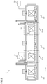
- FIG. 1 is a view illustrating a schematic configuration of a continuous nitriding treatment furnace according to an embodiment of the present invention.
- FIG. 2 is a chart roughly illustrating a temperature history of a steel member and a history of a nitriding potential. KN in process chambers, in steps of a continuous nitriding treatment according to the embodiment of the present invention.
- FIG. 3 is a view illustrating a schematic configuration of a continuous nitriding treatment furnace according to another embodiment of the present invention.
- FIG. 4 is a view illustrating the structure of a continuous nitriding treatment furnace A according to an example of the present invention.
- FIG. 5 is a view illustrating the structure of a continuous nitriding treatment furnace B according to an example of the present invention.
- FIG. 6 is a view illustrating the structure of a continuous nitriding treatment furnace C according to an example of the present invention.
- FIG. 7 is a view illustrating the structure of a continuous nitriding treatment furnace D according to a comparative example.
- FIG. 8 is a chart illustrating treatment conditions and test results of a nitriding treatment test.
- a continuous nitriding treatment furnace 1 has a plurality of process chambers, and includes, in order from an upstream side of a conveyor line L, a heating chamber in which a steel member S is heated, a first nitriding chamber 21 a in which an iron nitride compound layer is formed on a surface of the steel member S, a second nitriding chamber 21 b in which a ⁇ ′ phase is precipitated in the iron nitride compound layer of the steel member S, a cooling chamber 22 in which the steel member S is cooled, and a control part 30 that controls operation states of the furnace.
- the composition of the steel member S is not limited, and mechanical structural steel such as S25C, S35C, S45C, SCM415, SCM420, SCM435, or SACM645 is usable, for instance.
- the steel member is placed on a specialized jig when conveyed, but in FIG. 1 , it is referred to as the steel member S for convenience' sake.
- a carry-in port 2 through which the steel member S is carried in is formed, and a carry-in door 3 openable/closable in an up/down direction is provided on an outer surface of the furnace wall to insulate atmosphere gases inside and outside the furnace from each other.
- a carry-out port 4 through which the steel member S is carried out is formed, and an carry-out door 5 (Tenable/closable in the up/down direction is provided on an outer surface of the furnace wall to insulate the atmosphere gases inside and outside the furnace from each other.
- a roller hearth 6 for conveying the steel member S is provided on a hearth, and the steel member S carried into the furnace through the carry-in port 2 passes through the process chambers, namely, the heating chamber 20 , the first nitriding chamber 21 a , the second nitriding chamber 21 b , and the cooling chamber 22 to be carried out of the furnace through the carry-out port 4 .
- partition doors 7 a openable/closable in the up/down direction are provided to separate the atmosphere gases of the adjacent process chambers.
- the partition doors 7 a are not structured to strictly separate the atmosphere gases in the adjacent process chambers but is structured to allow the atmosphere gases in the adjacent process chambers to flow into each other through spaces above the partition doors 7 a , spaces of the roller hearth 6 under the partition doors 7 a , and so on as indicated by the arrows in FIG. 1 when the partition doors 7 a are closed.
- a partition door 7 b openable/closable in the up/down direction is also provided to separate the atmosphere gases of the process chambers from each other.
- the partition door 7 b is structured not to allow the atmosphere gases in the adjacent process chambers to easily flow into each other, unlike the aforesaid partition doors 7 a.
- a process gas supply pipe 8 through which a process gas for a nitriding treatment is supplied is provided to the first nitriding chamber 21 a .
- the process gas for the nitriding treatment in this embodiment (hereinafter, “process gas”) is composed of a NH 3 gas and a H 2 gas.
- the process gas supply pipe 8 connects to a ceiling portion near the heating chamber, in the first nitriding chamber 21 a .
- a gas analyzer 9 that measures a partial pressure of the atmosphere gas is further provided to the first nitriding chamber 21 a .
- the gas analyzer 9 is configured to be capable of measuring partial pressures of the gasses included in the process gas supplied into the first nitriding chamber 21 a , that is, partial pressures of the NH 3 gas and the H 2 gas.
- the connection position of the process gas supply pipe 8 to the first nitriding chamber 21 a is not limited to the position shown in this embodiment, but may be any position as long as the process gas can sufficiently diffuse in the first nitriding chamber 21 a from the position.
- an exhaust pipe 10 through which the atmosphere gas in the furnace is discharged is provided in a ceiling portion of the second nitriding chamber 21 b .
- the exhaust pipe 10 connects to the ceiling portion near the cooling chamber, in the second nitriding chamber 21 b .
- the connection position of the exhaust pipe 10 to the second nitriding chamber 21 b is not limited to the position shown in this embodiment, but may be any position as long as the discharge pipe 10 does not obstruct the atmosphere gas flowing from the inside of the first nitriding chamber 21 from sufficiently diffusing into the second nitriding chamber 21 b.
- the continuous nitriding treatment furnace 1 of this embodiment is configured such that the atmosphere gases in the first nitriding chamber 21 a and the second nitriding chamber 21 b are not strictly insulated from each other, and further the process gas supply pipe 8 connects to the first nitriding chamber 21 a and the exhaust pipe 10 connects to the second nitriding chamber 21 b , which makes the atmosphere gas in the first nitriding chamber 21 a easily flow into the second nitriding chamber 21 b .
- the atmosphere gas easily flows from the first nitriding chamber 21 a toward the heating chamber 20 since the process gas supply pipe 8 is provided to the first nitriding chamber 21 a .
- the heating chamber 20 , the first nitriding chamber 21 a , and the second nitriding chamber 21 b each have heaters 11 that adjust an atmosphere gas temperature in the process chamber. Further, the heating chamber 20 , the first nitriding chamber 21 a , the second nitriding chamber 21 b , and the cooling chamber 22 each have a stirring fan 12 that stirs the atmosphere gas in the process chamber to unify the atmosphere gas in the process chamber and unify the temperature of the steel member S.
- the control part 30 is configured to control the opening/closing timings of the carry-in door 3 , the carry-out door 5 , and the partition doors 7 a , 7 b , control the conveyance speed of the steel member S, control the rotation speed of the stirring fans 12 , control heat values of the heaters 11 based on the atmosphere gas temperatures in the process chambers, and control flow rates of the gasses included in the process gas based on the nitriding potential KN calculated from the partial pressures of the gasses included in the process gas in the first nitriding chamber 21 a as measured by the gas analyzer 9 .
- the control part 30 further controls the atmosphere gas temperature in the second nitriding chamber 21 b to a temperature lower than the atmosphere gas temperature in the first nitriding chamber 21 a by 25° C., to 150° C.′ by adjusting the heat values of the heaters 11 .
- the nitriding treatment that forms the iron nitride compound layer on the surface of the steel member S in the first nitriding chamber 21 a and precipitates the ⁇ ′ phase in the iron nitride compound layer in the second nitriding chamber 21 b is executed.
- the configuration of a control system of the control part 30 is not limited, and for example, a plurality of control systems may independently perform the aforesaid controls respectively, or one control system may centrally control the aforesaid controls.
- the continuous nitriding treatment furnace 1 is configured as described above. Next, a continuous nitriding treatment method using the continuous nitriding treatment furnace 1 will be described with reference to FIG. 1 and FIG. 2 .
- the treatments in the respective process chambers are started, with the carry-in door 3 , the carry-out door 5 , and the partition doors 7 a , 7 b being closed, then after a predetermined time passes, the carry-in door 3 , the carry-out door 5 , and the partition doors 7 a , 7 b are opened, and the steel member S is carried to the next process chamber.
- FIG. 2 is a chart roughly illustrating a temperature history of the steel member S and a history of the nitriding potential KN in the process chambers, in the steps of the continuous nitriding treatment of this embodiment.
- the steel member S is carried into the heating chamber 20 .
- the heating chamber 20 is kept at an atmosphere gas temperature equal to the atmosphere gas temperature in the first nitriding chamber 21 a .
- the steel member S is heated in the heating chamber 20 up to a temperature for the nitriding treatment.
- the steel member S is carried into the first nitriding chamber 21 a .
- the NH 3 gas and the H 2 gas have been supplied through the process gas supply pipe 8 , and the atmosphere gas in the first nitriding chamber 21 a has been in a state of having a nitriding potential KN with which the iron nitride compound layer is formed on the surface of the steel member S.
- the surface of the steel member S is nitrided and the iron nitride compound layer composed of an ⁇ phase or of the ⁇ phase and the ⁇ ′ phase is formed on the surface of the steel member S.
- the atmosphere gas temperature in the first nitriding chamber 21 a is preferably 550 to 625° C. If the atmosphere gas temperature in the first nitriding chamber 21 a is lower than 550° C., the generation speed of the iron nitride compound layer may become low. On the other hand, when the atmosphere gas temperature in the first nitriding chamber 21 a is higher than 625° C., the softening and strain of the steel member S may increase. Further, the nitriding potential KN of the atmosphere gas in the first nitriding chamber 21 a is preferably 0.25 to 1.0. If the nitriding potential KN is lower than 0.25, the generation speed of the iron nitride compound layer may become very low or the iron nitride compound layer itself may not be generated.
- the steel member S having the iron nitride compound layer formed thereon is carried to the second nitriding chamber 211 which is lower in the atmosphere gas temperature than the first nitriding chamber 21 a .
- the decomposition rate of the NH 3 gas supplied as the process gas is lower in the second nitriding chamber 21 b than in the first nitriding chamber 21 a . This makes the NH 3 gas more difficult to decrease and the H 2 , gas more difficult to increase in the second nitriding chamber 21 b than in the first nitriding chamber 21 a .
- the inside of the second nitriding chamber 21 b is in a state where the atmosphere gas of the first nitriding chamber 21 a flows thereto through the space between the partition door 7 a and the furnace wall. Accordingly, the atmosphere gases are exchanged between the first nitriding chamber 21 a and the second nitriding chamber 21 b.
- the partial pressure of the NH 3 gas in the second nitriding chamber 21 b becomes equal to or lower than the partial pressure of the NH 3 gas in the first nitriding chamber 21 a
- the partial pressure of the H 2 gas in the second nitriding chamber 21 b becomes equal to or more than the partial pressure of the H 2 gas in the first nitriding chamber 21 a .
- the nitriding potential KN of the second nitriding chamber 21 b becomes equal to or lower than the nitriding potential KN of the first nitriding chamber 21 a , and a value calculated by subtracting the nitriding potential KN of the first nitriding chamber 21 a from the nitriding potential KN of the second nitriding chamber 21 b becomes ⁇ 0.1 to 0.
- the nitriding potential KN of the second nitriding chamber 21 b is naturally determined by the nitriding potential KN of the first nitriding chamber 21 a .
- the atmosphere gas in the first nitriding chamber 21 a easily flows into the second nitriding chamber 21 b , and the value calculated by subtracting the nitriding potential KN of the first nitriding chamber 21 a from the nitriding potential KN of the second nitriding chamber 21 b easily becomes ⁇ 0.1 to 0.
- the atmosphere gas in the first nitriding chamber 21 a flows toward the heating chamber 20 through the space around the partition door 7 a . Accordingly, the heating chamber 20 and the first nitriding chamber 21 a are substantially equal in the nitriding potential KN as illustrated in FIG. 2 .
- the atmosphere gas temperature in the second nitriding chamber 21 b is preferably 475 to 550° C. If the atmosphere gas temperature in the second nitriding chamber 21 b is lower than 475° C., the precipitation of the ⁇ ′ phase may become slow, requiring a long treatment time. On the other hand, if the atmosphere gas temperature the second nitriding chamber 21 b is higher than 550° C., a fraction of the ⁇ ′ phase becomes low. Further, a difference by which the atmosphere gas temperature in the second nitriding chamber 21 b is lower than the atmosphere gas temperature in the first nitriding chamber 21 a is preferably 25° C. to 150° C.
- the precipitation of the ⁇ ′ phase may be difficult to occur in the second nitriding chamber 21 b .
- the temperature difference between the atmosphere gases in the first nitriding chamber 21 a and the second nitriding chamber 21 b is over 150° C., at least one of an increase in the softening and strain of the steel member S due to the too high atmosphere gas temperature in the first nitriding chamber 21 a and a delay in the precipitation of the ⁇ ′ phase due to the too low atmosphere gas temperature in the second nitriding chamber 21 b may occur.
- the atmosphere gas in the second nitriding chamber 21 b has such a nitriding potential KN that the value calculated by subtracting the nitriding potential KN of the first nitriding chamber 21 a from the nitriding potential KN of the second nitriding chamber 21 b becomes ⁇ 0.1 to 0 and the second nitriding chamber 21 b is lower in the atmosphere gas temperature than the first nitriding chamber 21 a as described above, a ratio of the ⁇ ′ phase which is a low-temperature stable phase increases in the iron nitride compound layer, making it possible to obtain a nitrided steel member excellent in pitting resistance and fatigue strength.
- the steel member S in which the ratio of the ⁇ ′ phase has increased in the second nitriding chamber 21 b is carried to the cooling chamber 22 to be cooled to a predetermined temperature. Thereafter, the steel member S is carried out of the furnace. This is the completion of the series of the nitriding treatment using the continuous nitriding treatment furnace 1 .
- the continuous nitriding treatment furnace 1 of this embodiment has a furnace structure such that the atmosphere gas temperature in the second nitriding chamber 21 b is lower than the atmosphere gas temperature in the first nitriding chamber 21 a , the atmosphere gas in the first nitriding chamber 21 a flows into the second nitriding chamber 21 b , and the nitriding potential KN of the second nitriding chamber 21 b is dependent on that of the first nitriding chamber 21 a .
- This structure makes it possible for the nitriding treatment that precipitates the ⁇ ′ phase in the iron nitride compound layer to be performed in the continuous furnace. This enables an increase in productivity of the nitrided steel member and a decrease in the treatment cost.
- the heating chamber 20 , the first nitriding chamber 21 a , the second nitriding chamber 21 b , and the cooling chamber 22 are provided as the process chambers configuring the continuous nitriding treatment furnace 1 , but the configuration of the process chambers is not limited to this.
- the configuration of the process chambers can be appropriately changed to a degree not inhibiting the nitriding treatment by the first nitriding chamber 21 a and the second nitriding chamber 21 b described in this embodiment.
- the process gas for the nitriding treatment is composed of the NH 3 gas and the H 2 gas, but the process gas for the nitriding treatment may include an inert gas such as, for example, a N 2 gas in addition to the NH 3 gas and the H 2 gas. That is, the supply of another gas in an amount not inhibiting the nitriding treatment of this embodiment in addition to the NH 3 gas and the H 2 gas is permitted.
- the N 2 gas it is preferable to supply the N 2 gas so as to be capable of maintaining a state where the partial pressure ratio of the NH 3 gas in the atmosphere gas becomes 0.1 or more.
- the nitriding chamber 21 is divided by the partition door 7 a into the different process chambers, namely, “the first nitriding chamber 21 a ” and “the second nitriding chamber 21 b ”, but in a case where the total length of the nitriding chamber 21 is long as in, for instance, FIG. 3 , by providing regions different in the atmosphere gas temperature in the same nitriding chamber 21 , it is possible to perform the same nitriding treatment as that in the above-described embodiment.
- the heat values of the heaters 11 are controlled so as to form a first nitriding zone 21 c and a second nitriding zone 21 d located downstream of the first nitriding zone 21 c in terms of the conveyor line and lower in the atmosphere gas temperature than the first nitriding zone 21 c by 25° C. to 150° C., as the regions different in the atmosphere gas temperature in the nitriding chamber. Consequently, the second nitriding zone 21 d has such an atmosphere gas that a value calculated by subtracting the nitriding potential KN of the first nitriding zone 21 c from the nitriding potential KN of the second nitriding zone 21 d becomes ⁇ 0.1 to 0.
- the process gas supply pipe 8 through which the NH 3 gas and the H 2 gas are supplied is provided at a position corresponding to the first nitriding zone 21 c
- the exhaust pipe 10 through which the atmosphere gas in the furnace is discharged is provided at a position corresponding to the second nitriding zone 21 d .
- only a roller hearth 13 of the nitriding chamber 21 is configured to operate independently of the roller hearths 6 of the other process chambers, for instance.
- the iron nitride compound layer composed of the ⁇ phase or of the ⁇ phase and the ⁇ phase is formed in the first nitriding zone 21 c , and thereafter, the steel member S is carried straight to the second nitriding zone 21 d .
- the steel member S is exposed to such an atmosphere gas that the value calculated by subtracting the nitriding potential KN of the first nitriding zone 21 c from the nitriding potential KN of the second nitriding zone 21 d becomes ⁇ 0.1 to 0 and that is lower in the atmosphere gas temperature than in the first nitriding zone 21 a by 25° C. to 150° C., resulting in an increase in the phase which is the low-temperature stable phase.
- providing the partition door 7 a between the first nitriding zone 21 c and the second nitriding zone 21 d to provide the nitriding zones as different process chambers as described in the previous embodiment permits the regions different in the atmosphere gas temperature to be more close to each other, making it possible to shorten the total length of the furnace.
- the partition door 7 a is provided between the heating chamber 20 and the first nitriding chamber 21 a , and this partition door 7 a is intended to prevent the atmosphere gas temperature in the first nitriding chamber 21 a from decreasing. Accordingly, the partition door 7 a between the heating chamber 20 and the first nitriding chamber 21 a may not be provided, as long as an influence that the decrease in the atmosphere gas temperature in the first nitriding chamber 21 a has on the quality of the nitrided steel member is on a permissible level.
- the exhaust pipe 10 through which the atmosphere gas in the furnace is discharged is provided only to the second nitriding chamber 21 b , but it may be further provided to the heating chamber 20 in addition to the second nitriding chamber 21 b .
- a change in the atmosphere gas in the first nitriding chamber 21 a becomes small, making it possible to reduce quality variation of the nitriding treatment.
- a structure in which an exhaust pipe is provided to a heating zone (not illustrated) provided upstream of the first nitriding zone in terms of the conveyor line makes it possible to obtain the same effect.
- a supply mechanism for supplying the process gas into the nitriding chamber and an exhaust mechanism for discharging the atmosphere gas in the furnace are not limited to the structures described in the previous embodiments.
- Steel members prepared as test pieces were subjected to a nitriding treatment using the continuous nitriding treatment furnace according to the present invention, and iron nitride compound layers of obtained nitrided steel members were evaluated.
- the composition of the steel members prepared as the test pieces is as shown in the following Table 1.
- the continuous nitriding treatment furnace As the continuous nitriding treatment furnace according to the present invention, three kinds of furnaces different in length of a process chamber as illustrated in FIG. 4 to FIG. 6 were used. Further, as a comparative example, a continuous nitriding treatment furnace without a second nitriding chamber as illustrated in FIG. 7 was also used.
- the furnace having the structure illustrated in FIG. 4 is referred to as a continuous nitriding treatment furnace A
- the furnace having the structure in FIG. 5 as a continuous nitriding treatment furnace B
- the furnace having the structure illustrated in FIG. 6 as a continuous nitriding treatment furnace C
- the furnace having the structure illustrated in FIG. 7 as a continuous nitriding treatment furnace D. Note that FIG. 4 to FIG.
- the furnaces each include the heaters, the gas analyzer, the control part, and so on illustrated in FIG. 1 . That is, in each of the furnaces, the opening/closing timings of the carry-in door and the carry-out door, the opening/closing timings of the partition doors, the conveyance speed of the steel member, the rotation speed of the stirring fans, the heat values of the heaters, the flow rates of the gasses included in the process gas for the nitriding treatment based on the nitriding potential KN of the nitriding chamber (the first nitriding chamber in the continuous nitriding treatment furnaces A to C) are controlled.
- the test piece placed on a jig moves downstream in terms of the conveyor line by a distance corresponding to one jig in a sixty minute cycle. That is, in the continuous nitriding treatment furnace A, the test piece carried into the furnace is carried out of the furnace after kept in the heating chamber for sixty minutes, in the first nitriding chamber for sixty minutes, in the second nitriding chamber for sixty minutes, and in the cooling chamber for sixty minutes. In the continuous nitriding treatment furnaces B, C, the test piece placed on a jig moves downstream in terms of the conveyor line by a distance corresponding to one jig in a thirty minute cycle.
- the test piece carried into the furnace is carried out of the furnace after kept in the heating chamber for thirty minutes, in the first nitriding chamber for sixty minutes, in the second nitriding chamber for ninety minutes, and in the cooling chamber for thirty minutes.
- the test piece carried into the furnace is carried out of the furnace after kept in the heating chamber for thirty minutes, in the first nitriding chamber for sixty minutes, in the second nitriding chamber for 120 minutes, and in the cooling chamber for thirty minutes.
- the test piece placed on a jig moves downstream in terms of the conveyor line by a distance corresponding to one jig in a sixty minute cycle. That is, in the continuous nitriding treatment furnace D, the test piece carried into the furnace is carried out of the furnace after kept in the heating chamber for sixty minutes, in the nitriding chamber for sixty minutes, and in the cooling chamber for sixty minutes.
- Treatment conditions of the continuous nitriding treatment are as shown in later-described Table 2. What [Temp1], [Temp2], [Time1], and [Time2] in Table 2 mean will be explained with reference to FIG. 8 .
- [Temp1] is an atmosphere gas temperature in the heating chamber and the first nitriding chamber. The test piece carried into the furnace is heated up to the temperature Temp1, and is subjected to the nitriding treatment in the first nitriding chamber while kept at this temperature.
- [Temp2] is an atmosphere gas temperature in the second nitriding chamber. In the test piece on whose surface the iron nitride compound layer has been formed in the first nitriding chamber, the precipitation of the ⁇ ′ phase is promoted in the second nitriding chamber.
- [Time1] is a treatment time in the first nitriding chamber.
- [Time2] is a treatment time in the second nitriding chamber. Note that in the continuous nitriding treatment furnaces A to C, a value calculated by subtracting the nitriding potential KN of the first nitriding chamber from the nitriding potential KN of the second nitriding chamber was ⁇ 0.1 to 0. Further, the heating chamber and the first nitriding chamber were substantially equal in the nitriding potential KN. Further, in the continuous nitriding treatment furnace D, the heating chamber and the nitriding chamber were substantially equal in the nitriding potential KN.
- a continuous gas analyzer (manufactured by ABB, Model AO2000-Uras26) was used for analyzing a NH 3 partial pressure
- a continuous gas analyzer (manufactured by ABB, Model AO2000-Caldos25) was used for analyzing a H 2 partial pressure.
- the process gas for the nitriding treatment is composed of a NH 3 gas and a H 2 gas
- the process gas for the nitriding treatment is composed of a NH 3 gas, a H 7 gas, and a N 2 gas.
- the flow rate of the N 2 gas was set to 1 ⁇ 3 of the flow rate of the H 2 gas so that a partial pressure ratio of the NH 3 gas in the process gas supplied into the first nitriding chamber became 0.1 or more, and the flow rates of the gases included in the process gas were controlled so that the nitriding potential.
- KN of the first nitriding chamber became 0.65.
- the thickness of each of the iron nitride compound layers and a ⁇ ′ fraction in each of the iron nitride compound layers were measured. Measuring methods of these items are as follows.
- the test piece was cut in a direction perpendicular to a worked surface (front surface) with a cutting machine, and its cross section was polished with emery paper, and the polished surface was mirror-finished with a buff. After corroded by a 3% nitric acid alcohol, the aforesaid cross section was observed at 400 magnifications with a metallographic (optical) microscope, and the thickness of the iron nitride compound layer was measured.
- the iron nitride compound layer which is also referred to as a white layer, appears white in addition to being different in structure from the base metal, and thus can be easily visually discriminated.
- the ⁇ ′ fracture was measured by EBSP analysis.
- an EBSP (Electron Back Scatter diffraction Pattern) device mounted on FE-SEM (Model: JSM7001F manufactured by JEOL) was used.
- the EBSP method is a method in which a Kikuchi pattern generated by electron back scattering diffraction when a sample greatly tilted by about 70° is irradiated with an electron beam in a SEM sample chamber is projected onto a phosphor screen, a projected image is taken in by a TV camera or the like, the pattern is indexed, and a crystal orientation at the irradiation point is measured.
- test piece was cut in the direction perpendicular to the worked surface (front surface) with a cutting machine, its cross section was polished with emery paper, thereafter mirror-polished with a diamond (grain size 1 ⁇ m) buff, and finished by being polished with colloidal silica abrasive grains (grain size 0.05 ⁇ m), and the resultant surface was used as a surface to be tested for the analysis.
- an analyzing process was performed by a Grain Dilation method using analysis software (OIM Analysis).
- OIM Analysis analysis software
- a crystal grain in which two or more adjacent pixels (measurement points) whose orientation difference was within 5° or which was not composed of two or more pixels was not regarded as a crystal grain but was absorbed in an adjacent grain.
- Phase MAP in which the ⁇ phase, the ⁇ phase, and the ⁇ ′ phase were separated was created, and a ratio of a sectional area occupied by the ⁇ ′ phase in the compound layer in the cross section being the surface to be tested of the test piece was calculated as the ⁇ ′ phase fraction, as expressed by the following expression (1).
- ⁇ ′ phase fraction (%) sectional area of the ⁇ ′ phase in the iron nitride compound layer/sectional area of the iron nitride compound layer ⁇ 100 (1)
- Comparative Example 2 even in the continuous nitriding treatment furnace B including the second nitriding chamber, if the atmosphere gas temperature in the first nitriding chamber is too low, the formation speed of the iron nitride compound layer becomes low, and the thickness of the iron nitride compound layer becomes thin. Further, as is seen from Comparative Examples 2, 3, when the atmosphere gas temperatures in the first nitriding chamber and the second nitriding chamber are not different, the increase in the ratio of the ⁇ ′ phase cannot be caused in the second nitriding chamber.
- the present invention is applicable to a nitriding treatment of a steel member.
Landscapes
- Chemical & Material Sciences (AREA)
- Engineering & Computer Science (AREA)
- Mechanical Engineering (AREA)
- Materials Engineering (AREA)
- Metallurgy (AREA)
- Organic Chemistry (AREA)
- Chemical Kinetics & Catalysis (AREA)
- Physics & Mathematics (AREA)
- Thermal Sciences (AREA)
- Crystallography & Structural Chemistry (AREA)
- General Engineering & Computer Science (AREA)
- Solid-Phase Diffusion Into Metallic Material Surfaces (AREA)
Abstract
Description
KN=P (NH3) /P (H2) 3/2
| TABLE 1 |
| CHEMICAL COMPOSITION (mass %) |
| C | Si | Mn | Cr | Fe |
| 0.095 | 0.2 | 0.9 | 1.4 | BALANCE |
γ′ phase fraction (%)=sectional area of the γ′ phase in the iron nitride compound layer/sectional area of the iron nitride compound layer×100 (1)
| TABLE 2 | |||||||||
| EXAMPLE/ | KN OF FIRST | COMPOUND | γ′ PHASE | ||||||
| COMPARATIVE | PROCESS | NITRIDING | Temp1 | Temp2 | Time1 | Time2 | LAYER | FRACTION | |
| EXAMPLE | FURNACE USED | GAS | CHAMBER | (° C.) | (° C.) | (min) | (min) | (μm) | (%) |
| EXAMPLE 1 | CONTINUOUS NITRIDING | NH3, H2 | 0.65 | 600 | 525 | 60 | 60 | 15 | 33 |
| TREATMENT FURNACE A | |||||||||
| EXAMPLE 2 | CONTINUOUS NITRIDING | NH3, H2 | 0.65 | 600 | 525 | 60 | 90 | 12 | 76 |
| TREATMENT FURNACE B | |||||||||
| EXAMPLE 3 | CONTINUOUS NITRIDING | NH3, H2 | 0.65 | 600 | 525 | 60 | 120 | 13 | 86 |
| TREATMENT FURNACE C | |||||||||
| EXAMPLE 4 | CONTINUOUS NITRIDING | NH3, H2 | 0.65 | 600 | 550 | 60 | 60 | 14 | 41 |
| TREATMENT FURNACE A | |||||||||
| EXAMPLE 5 | CONTINUOUS NITRIDING | NH3, H2 | 0.65 | 600 | 550 | 60 | 90 | 12 | 66 |
| TREATMENT FURNACE B | |||||||||
| EXAMPLE 6 | CONTINUOUS NITRIDING | NH3, H2 | 0.80 | 600 | 525 | 60 | 90 | 14 | 31 |
| TREATMENT FURNACE C | |||||||||
| EXAMPLE 7 | CONTINUOUS NITRIDING | NH3, H2 | 0.50 | 600 | 525 | 60 | 90 | 7 | 88 |
| TREATMENT FURNACE B | |||||||||
| EXAMPLE 8 | CONTINUOUS NITRIDING | NH3, H2, N2 | 0.65 | 575 | 500 | 60 | 90 | 8 | 70 |
| TREATMENT FURNACE B | |||||||||
| COMPARATIVE | CONTINUOUS NITRIDING | NH3, H2 | 0.65 | 600 | — | 60 | — | 14 | 9 |
| EXAMPLE 1 | TREATMENT FURNACE D | ||||||||
| COMPARATIVE | CONTINUOUS NITRIDING | NH3, H2 | 0.65 | 525 | 525 | 60 | 90 | 1 | — |
| EXAMPLE 2 | TREATMENT FURNACE B | ||||||||
| COMPARATIVE | CONTINUOUS NITRIDING | NH3, H2 | 0.65 | 550 | 550 | 60 | 90 | 2 | — |
| EXAMPLE 3 | TREATMENT FURNACE B | ||||||||
-
- 1 continuous nitriding treatment furnace
- 2 carry-in port
- 3 carry-in door
- 4 carry-out port
- 5 carry-out door
- 6 roller hearth
- 7 a partition door
- 7 b partition door
- 8 process gas supply pipe
- 9 gas analyzer
- 10 exhaust pipe
- 11 heater
- 12 stirring fan
- 13 roller hearth
- 20 heating chamber
- 21 nitriding chamber
- 21 a first nitriding chamber
- 21 b second nitriding chamber
- 21 c first nitriding zone
- 21 d second nitriding zone
- 22 cooling chamber
- 30 control part
- L conveyor line
- S steel member
Claims (14)
Applications Claiming Priority (4)
| Application Number | Priority Date | Filing Date | Title |
|---|---|---|---|
| JPJP2016-194241 | 2016-09-30 | ||
| JP2016194241 | 2016-09-30 | ||
| JP2016-194241 | 2016-09-30 | ||
| PCT/JP2017/034998 WO2018062290A1 (en) | 2016-09-30 | 2017-09-27 | Continuous nitriding treatment furnace and continuous nitriding treatment method |
Publications (2)
| Publication Number | Publication Date |
|---|---|
| US20190177829A1 US20190177829A1 (en) | 2019-06-13 |
| US11242592B2 true US11242592B2 (en) | 2022-02-08 |
Family
ID=61760770
Family Applications (1)
| Application Number | Title | Priority Date | Filing Date |
|---|---|---|---|
| US16/324,302 Active 2038-06-09 US11242592B2 (en) | 2016-09-30 | 2017-09-27 | Continuous nitriding treatment furnace and continuous nitriding treatment method |
Country Status (4)
| Country | Link |
|---|---|
| US (1) | US11242592B2 (en) |
| JP (1) | JP6908485B2 (en) |
| CN (1) | CN109312444B (en) |
| WO (1) | WO2018062290A1 (en) |
Families Citing this family (5)
| Publication number | Priority date | Publication date | Assignee | Title |
|---|---|---|---|---|
| JP7434018B2 (en) * | 2019-03-29 | 2024-02-20 | Dowaサーモテック株式会社 | Nitriding method for steel parts |
| CN110438439B (en) * | 2019-08-30 | 2021-03-19 | 武汉钢铁有限公司 | Atmosphere region adjustable nitriding device and continuous gas nitriding process thereof |
| JP7385443B2 (en) * | 2019-11-22 | 2023-11-22 | 川崎重工業株式会社 | Manufacturing method for soft nitrided steel parts |
| JP7415154B2 (en) * | 2019-12-24 | 2024-01-17 | 日本製鉄株式会社 | Manufacturing method for nitrided steel parts |
| JP7691090B2 (en) * | 2021-02-17 | 2025-06-11 | パーカー熱処理工業株式会社 | Nitriding method for steel members |
Citations (7)
| Publication number | Priority date | Publication date | Assignee | Title |
|---|---|---|---|---|
| JPH04214852A (en) | 1990-03-27 | 1992-08-05 | Koyo Rindobaagu Kk | Nitriding treatment |
| US5273585A (en) * | 1990-03-27 | 1993-12-28 | Mazda Motor Corporation | Heat-treating apparatus |
| CN102168275A (en) | 2011-04-02 | 2011-08-31 | 上海电机学院 | Heat treatment technology for improving the surface hardness of precise rolling ball bearing |
| JP2013227674A (en) | 2012-03-30 | 2013-11-07 | Kobe Steel Ltd | Gear excellent in seizure resistance |
| WO2015046593A1 (en) | 2013-09-30 | 2015-04-02 | Dowaサーモテック株式会社 | Method for nitriding steel member |
| WO2016005073A1 (en) | 2014-07-11 | 2016-01-14 | Robert Bosch Gmbh | Method for nitriding a component of a fuel injection system |
| WO2016024923A1 (en) | 2014-08-10 | 2016-02-18 | Thai Parkerizing Co., Ltd. | Method for surface hardening treatment of steel member and surface hardening treatment apparatus |
Family Cites Families (3)
| Publication number | Priority date | Publication date | Assignee | Title |
|---|---|---|---|---|
| JP2014055337A (en) * | 2012-09-13 | 2014-03-27 | Hitachi Constr Mach Co Ltd | Nitrided member and hydraulic rotary machine using the same |
| EP2966189B8 (en) * | 2013-03-08 | 2019-08-21 | Nippon Steel Corporation | Semi-finished material for induction hardened component and method for producing same |
| KR101957084B1 (en) * | 2015-03-25 | 2019-06-24 | 닛폰세이테츠 가부시키가이샤 | Nitriding and softening treated parts excellent in abrasion resistance and inner fitability and nitriding and softening treatment methods |
-
2017
- 2017-09-27 JP JP2017186464A patent/JP6908485B2/en active Active
- 2017-09-27 CN CN201780037897.7A patent/CN109312444B/en active Active
- 2017-09-27 US US16/324,302 patent/US11242592B2/en active Active
- 2017-09-27 WO PCT/JP2017/034998 patent/WO2018062290A1/en not_active Ceased
Patent Citations (13)
| Publication number | Priority date | Publication date | Assignee | Title |
|---|---|---|---|---|
| JPH04214852A (en) | 1990-03-27 | 1992-08-05 | Koyo Rindobaagu Kk | Nitriding treatment |
| US5273585A (en) * | 1990-03-27 | 1993-12-28 | Mazda Motor Corporation | Heat-treating apparatus |
| US5871806A (en) | 1990-03-27 | 1999-02-16 | Mazda Motor Corporation | Heat-treating process |
| CN102168275A (en) | 2011-04-02 | 2011-08-31 | 上海电机学院 | Heat treatment technology for improving the surface hardness of precise rolling ball bearing |
| JP2013227674A (en) | 2012-03-30 | 2013-11-07 | Kobe Steel Ltd | Gear excellent in seizure resistance |
| US20150038380A1 (en) | 2012-03-30 | 2015-02-05 | Kabushiki Kaisha Kobe Seiko Sho(Kobe Steel, Ltd.) | Gear having excellent seizing resistance |
| WO2015046593A1 (en) | 2013-09-30 | 2015-04-02 | Dowaサーモテック株式会社 | Method for nitriding steel member |
| CN105593394A (en) | 2013-09-30 | 2016-05-18 | 同和热处理技术株式会社 | Nitriding treatment method for steel components |
| US20160244869A1 (en) | 2013-09-30 | 2016-08-25 | Dowa Thermotech Co., Ltd. | Nitriding process method of steel member |
| WO2016005073A1 (en) | 2014-07-11 | 2016-01-14 | Robert Bosch Gmbh | Method for nitriding a component of a fuel injection system |
| US20170138326A1 (en) | 2014-07-11 | 2017-05-18 | Robert Bosch Gmbh | Method for nitriding a component of a fuel injection system |
| WO2016024923A1 (en) | 2014-08-10 | 2016-02-18 | Thai Parkerizing Co., Ltd. | Method for surface hardening treatment of steel member and surface hardening treatment apparatus |
| JP2016065263A (en) | 2014-08-10 | 2016-04-28 | タイ パーカライジング カンパニー リミテッドThai Parkerizing Co.,Ltd. | Method and apparatus for surface hardening treatment of steel member |
Non-Patent Citations (2)
| Title |
|---|
| Chinese Office and Search Report, Chinese Patent Office, Application No. 201780037897.7, dated Mar. 24, 2020. |
| International Search Report in International Patent Application No. PCT/JP2017/034998, dated Nov. 14, 2017. |
Also Published As
| Publication number | Publication date |
|---|---|
| JP2018059195A (en) | 2018-04-12 |
| CN109312444A (en) | 2019-02-05 |
| JP6908485B2 (en) | 2021-07-28 |
| WO2018062290A1 (en) | 2018-04-05 |
| US20190177829A1 (en) | 2019-06-13 |
| CN109312444B (en) | 2021-01-15 |
Similar Documents
| Publication | Publication Date | Title |
|---|---|---|
| US11242592B2 (en) | Continuous nitriding treatment furnace and continuous nitriding treatment method | |
| JP3852010B2 (en) | Vacuum heat treatment method and apparatus | |
| US9493856B2 (en) | Furnace system for the controlled heat treatment of sheet metal components | |
| CN105593394B (en) | Nitriding treatment method for steel components | |
| CN106929659B (en) | Heat-treatment furnace and heat-treating methods and method for manufacturing motor vehicle component are carried out for the plate slab to precoated shet | |
| JP7434018B2 (en) | Nitriding method for steel parts | |
| CN114341392B (en) | Vacuum carburization method and carburized component manufacturing method | |
| JP5209921B2 (en) | Heat treatment method and heat treatment equipment | |
| CN110199036B (en) | Dynamic adjustment method for manufacturing heat-treated steel sheet | |
| Kula et al. | FineCarb-the flexible system for low pressure carburizing. New options and performance | |
| JP2020007603A (en) | Carburized quenching device and carburized quenching method | |
| WO2016159235A1 (en) | Method for nitriding steel member | |
| JP2009091638A (en) | Heat-treatment method and heat-treatment apparatus | |
| US20200232063A1 (en) | Method and furnace for thermally treating a high-resistance steel strip comprising a temperature homogenisation chamber | |
| JP2005272884A (en) | Gas nitriding method | |
| WO2019182140A1 (en) | Vacuum carburization processing method, and method for manufacturing carburized component | |
| JP2009046700A (en) | Heat treatment method and heat treatment equipment | |
| CN103459616B (en) | The method of thermal treatment coated metal band and heat treated coated metal band | |
| JP3028995B2 (en) | Method for continuous carburization of metal strip and sheet temperature control | |
| JP6724201B2 (en) | Nitriding apparatus and nitriding method | |
| JP2008303444A (en) | Continuous carburizing method | |
| WO2024042744A1 (en) | Method for manufacturing carburized sintered body and apparatus for manufacturing carburized sintered body | |
| JP2021109990A (en) | Plate temperature control method, heating control device and method for producing metal plate | |
| JP2004002913A (en) | Method for predicting alloying temperature of hot-dip galvanized steel sheet | |
| JP2020063497A (en) | Method and apparatus for controlling temperature of metal strip |
Legal Events
| Date | Code | Title | Description |
|---|---|---|---|
| AS | Assignment |
Owner name: DOWA THERMOTECH CO., LTD., JAPAN Free format text: ASSIGNMENT OF ASSIGNORS INTEREST;ASSIGNORS:SHIMIZU, KATSUSHIGE;HATANAKA, HOKUTO;SUN, BIN;AND OTHERS;SIGNING DATES FROM 20181109 TO 20181126;REEL/FRAME:048289/0587 |
|
| FEPP | Fee payment procedure |
Free format text: ENTITY STATUS SET TO UNDISCOUNTED (ORIGINAL EVENT CODE: BIG.); ENTITY STATUS OF PATENT OWNER: LARGE ENTITY |
|
| STPP | Information on status: patent application and granting procedure in general |
Free format text: DOCKETED NEW CASE - READY FOR EXAMINATION |
|
| STPP | Information on status: patent application and granting procedure in general |
Free format text: RESPONSE TO NON-FINAL OFFICE ACTION ENTERED AND FORWARDED TO EXAMINER |
|
| STPP | Information on status: patent application and granting procedure in general |
Free format text: NON FINAL ACTION MAILED |
|
| STPP | Information on status: patent application and granting procedure in general |
Free format text: FINAL REJECTION MAILED |
|
| STPP | Information on status: patent application and granting procedure in general |
Free format text: EX PARTE QUAYLE ACTION MAILED |
|
| STPP | Information on status: patent application and granting procedure in general |
Free format text: RESPONSE TO EX PARTE QUAYLE ACTION ENTERED AND FORWARDED TO EXAMINER |
|
| STPP | Information on status: patent application and granting procedure in general |
Free format text: NOTICE OF ALLOWANCE MAILED -- APPLICATION RECEIVED IN OFFICE OF PUBLICATIONS |
|
| STPP | Information on status: patent application and granting procedure in general |
Free format text: PUBLICATIONS -- ISSUE FEE PAYMENT RECEIVED |
|
| STPP | Information on status: patent application and granting procedure in general |
Free format text: PUBLICATIONS -- ISSUE FEE PAYMENT VERIFIED |
|
| STCF | Information on status: patent grant |
Free format text: PATENTED CASE |
|
| MAFP | Maintenance fee payment |
Free format text: PAYMENT OF MAINTENANCE FEE, 4TH YEAR, LARGE ENTITY (ORIGINAL EVENT CODE: M1551); ENTITY STATUS OF PATENT OWNER: LARGE ENTITY Year of fee payment: 4 |