US11241259B2 - Bone anchor - Google Patents
Bone anchor Download PDFInfo
- Publication number
- US11241259B2 US11241259B2 US16/550,637 US201916550637A US11241259B2 US 11241259 B2 US11241259 B2 US 11241259B2 US 201916550637 A US201916550637 A US 201916550637A US 11241259 B2 US11241259 B2 US 11241259B2
- Authority
- US
- United States
- Prior art keywords
- anchor
- housing
- angled notch
- substantially planar
- planar face
- Prior art date
- Legal status (The legal status is an assumption and is not a legal conclusion. Google has not performed a legal analysis and makes no representation as to the accuracy of the status listed.)
- Active, expires
Links
Images


Classifications
-
- A—HUMAN NECESSITIES
- A61—MEDICAL OR VETERINARY SCIENCE; HYGIENE
- A61B—DIAGNOSIS; SURGERY; IDENTIFICATION
- A61B17/00—Surgical instruments, devices or methods
- A61B17/56—Surgical instruments or methods for treatment of bones or joints; Devices specially adapted therefor
- A61B17/58—Surgical instruments or methods for treatment of bones or joints; Devices specially adapted therefor for osteosynthesis, e.g. bone plates, screws or setting implements
- A61B17/68—Internal fixation devices, including fasteners and spinal fixators, even if a part thereof projects from the skin
- A61B17/70—Spinal positioners or stabilisers, e.g. stabilisers comprising fluid filler in an implant
- A61B17/7001—Screws or hooks combined with longitudinal elements which do not contact vertebrae
- A61B17/7035—Screws or hooks, wherein a rod-clamping part and a bone-anchoring part can pivot relative to each other
- A61B17/7038—Screws or hooks, wherein a rod-clamping part and a bone-anchoring part can pivot relative to each other to a different extent in different directions, e.g. within one plane only
-
- A—HUMAN NECESSITIES
- A61—MEDICAL OR VETERINARY SCIENCE; HYGIENE
- A61B—DIAGNOSIS; SURGERY; IDENTIFICATION
- A61B17/00—Surgical instruments, devices or methods
- A61B17/56—Surgical instruments or methods for treatment of bones or joints; Devices specially adapted therefor
- A61B17/58—Surgical instruments or methods for treatment of bones or joints; Devices specially adapted therefor for osteosynthesis, e.g. bone plates, screws or setting implements
- A61B17/68—Internal fixation devices, including fasteners and spinal fixators, even if a part thereof projects from the skin
- A61B17/70—Spinal positioners or stabilisers, e.g. stabilisers comprising fluid filler in an implant
- A61B17/7001—Screws or hooks combined with longitudinal elements which do not contact vertebrae
- A61B17/7032—Screws or hooks with U-shaped head or back through which longitudinal rods pass
- A61B17/7034—Screws or hooks with U-shaped head or back through which longitudinal rods pass characterised by a lateral opening
-
- A—HUMAN NECESSITIES
- A61—MEDICAL OR VETERINARY SCIENCE; HYGIENE
- A61B—DIAGNOSIS; SURGERY; IDENTIFICATION
- A61B17/00—Surgical instruments, devices or methods
- A61B17/56—Surgical instruments or methods for treatment of bones or joints; Devices specially adapted therefor
- A61B17/58—Surgical instruments or methods for treatment of bones or joints; Devices specially adapted therefor for osteosynthesis, e.g. bone plates, screws or setting implements
- A61B17/68—Internal fixation devices, including fasteners and spinal fixators, even if a part thereof projects from the skin
- A61B17/70—Spinal positioners or stabilisers, e.g. stabilisers comprising fluid filler in an implant
- A61B17/7001—Screws or hooks combined with longitudinal elements which do not contact vertebrae
- A61B17/7035—Screws or hooks, wherein a rod-clamping part and a bone-anchoring part can pivot relative to each other
- A61B17/7037—Screws or hooks, wherein a rod-clamping part and a bone-anchoring part can pivot relative to each other wherein pivoting is blocked when the rod is clamped
-
- A—HUMAN NECESSITIES
- A61—MEDICAL OR VETERINARY SCIENCE; HYGIENE
- A61B—DIAGNOSIS; SURGERY; IDENTIFICATION
- A61B17/00—Surgical instruments, devices or methods
- A61B17/56—Surgical instruments or methods for treatment of bones or joints; Devices specially adapted therefor
- A61B17/58—Surgical instruments or methods for treatment of bones or joints; Devices specially adapted therefor for osteosynthesis, e.g. bone plates, screws or setting implements
- A61B17/68—Internal fixation devices, including fasteners and spinal fixators, even if a part thereof projects from the skin
- A61B17/84—Fasteners therefor or fasteners being internal fixation devices
- A61B17/86—Pins or screws or threaded wires; nuts therefor
- A61B17/8685—Pins or screws or threaded wires; nuts therefor comprising multiple separate parts
Definitions
- This document pertains generally, but not by way of limitation, to systems and methods for fixation of bones during orthopedic procedures. More particularly, this disclosure relates to, but not by way of limitation, vertebral bone anchors.
- Orthopedic devices such as rods, plates, tethers, staples, and other devices can be used in various spinal procedures to correct abnormalities (e.g., scoliosis) or to address injuries (e.g., vertebral fracture).
- anchors and rods can be secured along a vertebral column to vertebrae to stabilize a region of the spine.
- pedicle screws or vertebral anchors
- FIG. 1 illustrates an exploded view of an anchor assembly from an anterior perspective, in accordance with at least one example of this disclosure.
- FIG. 2 illustrates a cross-sectional view of an anchor assembly across section 2 - 2 of FIG. 1 , in accordance with at least one example of this disclosure.
- FIG. 3A illustrates an isometric view of an anchor assembly, in accordance with at least one example of this disclosure.
- FIG. 3B illustrates an isometric view of an anchor assembly, in accordance with at least one example of this disclosure.
- FIG. 3C illustrates an isometric view of an anchor assembly, in accordance with at least one example of this disclosure.
- FIG. 4 illustrates a lateral view of a vertebral column and fixation assembly, in accordance with at least one example of this disclosure.
- FIG. 5A illustrates an isometric view of an anchor housing, in accordance with at least one example of this disclosure.
- FIG. 5B illustrates an isometric view of an anchor housing, in accordance with at least one example of this disclosure.
- FIG. 5C illustrates a bottom view of an anchor housing, in accordance with at least one example of this disclosure.
- FIG. 6 illustrates a bottom view of an anchor housing, in accordance with at least one example of this disclosure.
- FIG. 7 illustrates a bottom view of an anchor housing, in accordance with at least one example of this disclosure.
- FIG. 8 illustrates a bottom view of an anchor housing, in accordance with at least one example of this disclosure.
- FIG. 9 illustrates a bottom view of an anchor housing, in accordance with at least one example of this disclosure.
- Bone anchors can be used together with connecting members (such as rigid and semi-rigid rods) to straighten a region of a human spine to address an abnormality (e.g., scoliosis), to stabilize a spine following an injury (e.g., fractured vertebrae), or to address degeneration of the spine caused by disease.
- connecting members such as rigid and semi-rigid rods
- anchors are driven into vertebrae and are manipulated from outside of the cavities.
- the housing of the anchor can be positioned with respect to the shank of the anchor and the housings can be individually and collectively positioned along the spinal column to receive a connecting rod.
- the connecting rod can extend through two or more housings and can be secured to each housing by a closure top or set screw.
- disruption of muscle around the vertebral column may be reduced by using a technique that secures vertebral anchors along a cortical trajectory. That is, the trajectory along which the shank of the anchor extends into the vertebra to which it is secured can be through primarily cortical bone as opposed to a standard trajectory where the shank can extend into the vertebral body. In addition to helping to limit muscle disruption, this technique may enable use of smaller diameter and length anchors while maintaining good fixation.
- the cortical trajectory can require relatively larger angulation of the shank relative to the housing of the anchor in the medial to lateral and/or caudal to cranial directions. Further, because these procedures are performed with relative little work space (within a retracted opening), it is desirable to achieve relatively large angulation at multiple positions of the shank relative to the housing while still retaining the shank within the housing.
- this disclosure addresses these problems by including rounded notches in a distal end of the housing. More specifically, to provide the angulation required for use of a cortical trajectory, this disclosure proposes to use a secondary bore in the anchor housing that includes, in one example, rounded notches or corners configured to allow for a relatively high degree of angulation of the anchor relative to the housing to allow the cortical trajectory to be used while still allowing the housings to be aligned to accept a connecting rod.
- the anchor housing can include multiple rounded notches in a symmetrical arrangement (such as a square shape with rounded corners from a distal perspective). This can allow the housing to be positioned at the required angulation relative to the anchor when the housing in multiple positions, helping to reduce a requirement of orienting the housing relative to the anchor, which can save time and energy during a procedure.
- FIG. 1 illustrates an exploded view of an anchor assembly 100 from an anterior perspective, in accordance with at least one example of this disclosure.
- the anchor assembly 100 can include a housing and an anchor insertable through the housing and into bone for securing the anchor assembly 100 to a bone, in some examples.
- the anchor assembly 100 can include an anchor 102 , a housing 104 , a lower piston 106 , a biasing element 108 , and an upper piston 110 .
- the anchor 102 can include a head 112 and a shank 114 .
- the housing 104 can include a proximal portion 115 , an anchor bore 116 , and a distal portion 117 . Also shown in FIG. 1 are axis A and orientation indicators Proximal and Distal.
- the anchor 102 can be a fastener configured to secure to a work piece, such as a bone, plate, prosthesis, or other device used in a surgery or operation.
- the anchor 102 can be configured to engage wood, plastics, metals, and the like, for applications outside of surgical procedures.
- Anchor 102 can be comprised of plastics, metals, composites, combinations thereof, and the like.
- the anchor 102 can be comprised of biocompatible materials such as such as stainless steels, cobalt-chromium, titanium variations, polyether ether ketone (PEEK), and combinations thereof.
- the anchor 102 can include a head 112 located at a proximal portion of the anchor 102 , which can connect to the shank 114 .
- the head 112 can have a diameter larger than that of the shank 114 in some examples such that the shank 114 can extend through the housing 104 and so that the head 112 is limited from passing through a distal opening of the housing 104 .
- the shank 114 can extend distally away from the head 112 and can include a threaded portion, in some examples, for engaging bone.
- the housing 104 can include the proximal portion 115 connected the distal portion 117 with the anchor bore 116 extending through a proximal end of the proximal portion 115 along axis A and terminating within the distal portion 117 .
- the anchor assembly 100 can be a top-loading assembly.
- the housing 104 can include a secondary opening to allow the shank 112 to extend through the housing but not the head 112 .
- the housing 104 can thereby be configured to the head 112 in the housing 104 .
- the lower piston 106 can be a supporting member configured to engage the head 112 and to be supported thereby.
- the biasing element 108 can be a resilient element such as a spring. In some examples, the biasing element 108 can be a wave spring. In other examples, the biasing element 108 can be other springs or resilient members, such as a compression spring or compressible and resilient members comprised of materials such as rubbers, plastic, and the like.
- the upper piston 110 can be a supporting member configured to engage a proximal portion of the biasing element and configured to support a connecting member (shown in FIG. 2 ).
- the shank 114 of the anchor 102 can be inserted proximally-to-distally through the anchor bore 116 of the housing 104 such that the shank 114 extends distally out of the housing 104 .
- the shank 114 can then be secured to a bone of a patient, as discussed below in further detail.
- a position of the housing 104 relative to the anchor 102 can be set during securing of the shank 114 into the bone. The position can be fixed by a force applied on the housing 104 by the head 112 when the shank 114 is secured to the bone.
- the lower piston 106 , the biasing element 108 , and the upper piston 110 can be inserted into the anchor bore 116 such that the lower piston 106 engages the head 112 .
- the biasing element 108 can be disposed between the lower piston 106 and the upper piston 110 to bias the upper piston 110 away from the lower piston.
- the upper piston 110 can receive the connecting member therein, which can be secured within the housing 104 by a closure top or set screw.
- the secondary bore (or opening) in the distal portion 117 of the housing 104 can be configured to allow the anchor 102 to be oriented at various angles with respect to axis A and therefore relative to the housing 104 . More accurately, when the anchor 102 is secured to bone, the housing 104 can be oriented at various positions relative to the anchor 102 and to the bone. In some examples, the housing 104 can allow for the anchor 102 to be positioned at relatively extreme angles (such as 30 degrees, 35 degrees, 40 degrees, and the like) with respect to axis A to allow for the anchor 102 to be secured to a vertebra using a cortical bone technique.
- anchor assembly 100 can be used in various other vertebral anchoring techniques where the benefits of the anchor assembly 100 (such as the anchor 102 can be oriented at various angles with respect to the housing 104 ) can be useful.
- FIG. 2 illustrates a cross-sectional view of the anchor assembly 100 across section 2 - 2 of FIG. 1 , in accordance with at least one example of this disclosure.
- the anchor assembly 100 can include the anchor 102 , the housing 104 , the lower piston 106 , the biasing element 108 , the upper piston 110 , and the connecting rod 118 .
- the anchor 102 can include the head 112 , the shank 114 , a tool interface 120 , and a neck 121 .
- the housing 104 can include the proximal portion 115 , the anchor bore 116 , the distal portion 117 , a secondary bore 122 , the anchor threading (helical groove) 124 , a head bore 126 , a retaining portion 127 , a piston bore 128 , and closure top threading 130 .
- the lower piston 106 can include a washer notch 133 .
- the upper piston 110 can include a washer notch 134 . Also shown in FIG. 2 are axis A, diameter D 1 , diameter D 2 , diameter D 3 , and orientation indicators Proximal and Distal.
- Anchor assembly 100 of FIG. 2 can be consistent with anchor assembly 100 of FIG. 1 , except that FIG. 2 shows additional details of anchor assembly 100 .
- FIG. 2 shows the tool interface 120 of head 112 which can be configured to interface with a tool and/or a tool bit to receive a torque from a tool to rotate the anchor 104 into and/or out of a bore (such as a bore in a vertebra).
- FIG. 2 also shows that anchor 102 can include the neck 121 , which can be a necked-down (or reduced diameter) portion of the anchor 104 connecting the head 112 to the shank 114 .
- the neck 121 can have the diameter of D 1
- the head 112 can have the diameter D 2
- the shank can have the diameter D 3 .
- the neck 121 can be positioned along the anchor 102 such that the neck 121 is the portion of the anchor 121 that contacts the distal portion 117 of the housing 104 to limit rotation or angulation of the anchor 102 with respect to (or relative to) the housing 104 .
- the housing 104 can also include the secondary bore 122 , which can be an undercut, opening, or series of bevels at a distal end of the distal portion 117 of the housing 104 .
- the secondary bore 122 can be configured to contact the neck 121 to limit the angulation or relative angle of the anchor 102 with respect to the housing 104 .
- the housing 104 can also include the anchor threading (or helical groove) 124 , which can be threading in the housing 104 .
- the helical groove can be positioned in the housing 104 where the housing 104 tapers radially inward to create the retaining portion 127 (at the distal portion 117 ).
- the radially inward taper of the retaining portion 127 can be configured to retain the head 112 of the anchor 102 in the housing 104 . Because the threading of the shank 114 can be as wide or wider than the head 112 of the anchor, anchor threading 124 can be required to allow the shank 114 to pass through the retaining portion 127 of the housing 104 .
- the head bore 126 of the housing 104 can be sized to allow the head 112 to pass through to the retaining portion 127 of the housing 104 where the head 112 can be retained.
- the head bore 126 can also be sized to retain the bottom piston 106 therein.
- the piston bore 128 can be sized to receive the top piston 110 in the housing, where the top piston includes a flared portion having a diameter larger than that of the bottom piston 106 .
- the top piston 110 can be configured to support the connecting member 118 within the housing 104 .
- the closure top threading 130 can be threading in housing 104 configured to threadably receive a closure top to secure the connecting member 118 within the anchor bore 116 of the housing 104 .
- the washer notch 133 of the lower piston 106 can be a notch or undercut in the lower piston 106 sized and shaped to partially retain the biasing element 108 .
- the washer notch 134 of the upper piston 110 can be a notch or undercut in the upper piston 110 sized and shaped to partially retain the biasing element 108 .
- the washer notches 133 and 134 and the housing bore 126 can contact the biasing element to retain the biasing element 108 between the lower piston 106 and the upper piston 110 to bias the upper piston 110 away from the lower piston.
- FIG. 3A illustrates an isometric view of the anchor assembly 100 from an anterior perspective, in accordance with at least one example of this disclosure.
- FIG. 3B illustrates an isometric view of the anchor assembly 100 from a lateral perspective, in accordance with at least one example of this disclosure.
- FIG. 3C illustrates an isometric view of an anchor assembly from a distal perspective, in accordance with at least one example of this disclosure.
- FIGS. 3A, 3B, and 3C are discussed below concurrently.
- the anchor assembly 100 can include the anchor 102 , and the housing 104 .
- the anchor 102 can include the head 112 , the shank 114 , and the neck 121 .
- the housing 104 can include the proximal portion 115 , the anchor bore 116 , the distal portion 117 , and the secondary bore 122 .
- the secondary bore 122 can include corner notches 130 a - 130 d (a first angled notch 130 a , a second angled notch 130 b , a third angled notch 130 c , and a fourth angled notch 130 d ; collectively referenced as corner notches 130 ) and straight portions 132 a - 132 d (visible in FIG. 3C only and). Also shown in FIGS. 3A-3C are axis A 1 , axis A 2 , axis A 3 , angle ⁇ , and orientation indicators Proximal, Distal, Medial, Lateral, Anterior, and Posterior.
- Anchor assembly 100 of FIGS. 3A-3C can be consistent with anchor assembly 100 of FIGS. 1 and 2 , except that FIGS. 3A-3C show additional details of anchor assembly 100 .
- FIG. 3B shows how the neck 121 can contact the corner notch 130 d of the secondary opening 122 to obtain the angle ⁇ of angulation of the anchor 102 with respect to the housing 104 .
- the secondary opening 122 can include multiple edges, such as bevels, chamfers, J grooves, scotias, or the like.
- the secondary opening can include corner notches 130 a - 130 d which can each be rounded corner bevels, where each of the plurality of bevels curves along a face of each of the corner notches 130 a - 130 d.
- each of the corner notches 130 can be connected by straight portions 132 a - 132 d .
- each of straight portions 132 a - 132 d can be bevels in the secondary opening 122 , each having a substantially flat or planar face.
- the first straight portion 132 a can be connected to the first angled notch 130 a and the second angled notch 130 b ; the second straight portion 132 b can be connected to the second angled notch 130 b and the third angled notch 130 c ; the third straight portion 132 c can be connected to the third angled notch 130 c and the fourth angled notch 130 d ; and, the fourth straight portion 132 d can be connected to the first angled notch 130 a and the fourth angled notch 130 d.
- This example of the secondary opening 122 can have a geometric shape substantially of a square with rounded corners from a distal perspective (as shown in FIG. 3C ). As shown in FIGS. 3A-3C contact between the neck 121 and angled notch 130 d can create an angulation of the shank 114 with respect to the housing 104 at the angle ⁇ , where the angle ⁇ is the angle between axis A 1 (of the housing 104 and housing anchor bore 116 ) and axis A 2 (extending along anchor 102 ). In some examples, the angle ⁇ can be 5, 10, 15, 20, 25, 30, 35, 40, 45, 50, 55 degrees, or the like (including degrees between values listed).
- the ability to provide the angle ⁇ at high angulation can allow for the anchor assembly 100 to be used in a procedure where the anchor 102 is installed using a cortical trajectory. Also, the anchor assembly 100 can be useful in various other vertebral anchor installation techniques where high angulation is desired or required.
- the anchor assembly 100 provides an anchor housing 104 that is symmetrical about two planes and therefore can be quickly positioned to a desired orientation during a procedure, helping to save the physician time and energy during what can be a relatively time-intensive procedure.
- each of the angled notches 130 a - 130 d can produce an angle ⁇ that is the same. In other examples, each of the angled notches 130 a - 130 d can produce an angle ⁇ that is different.
- FIG. 4 illustrates a lateral perspective of a vertebral column 10 and a fixation assembly 400 , in accordance with at least one example of this disclosure.
- the fixation assembly 400 can be secured to the vertebral column 10 , as discussed in further detail below. Any of the previously discussed anchor assemblies can be secured to such a vertebral column.
- Vertebral column 10 can include a vertebra 12 , which can include a vertebral body 14 , a disk 16 , a spinous process 18 , and a transverse process 20 .
- the fixation assembly 400 can include housings 402 a - 402 b , a connecting member 404 , and anchors 406 a - 406 d , where each of the housings 402 a - 402 b corresponds to one of the anchors 406 a - 406 d .
- the fixation assembly 400 of FIG. 4 can operate consistently with the assemblies described in FIGS. 1-3C above, except that FIG. 4 shows the assembly 400 installed in vertebral column 10 . As shown in FIG. 4 , each of the anchors 406 a - 406 d are secured to cortical bone of individual vertebra of the vertebral column 10 .
- the anchors 406 a - 406 d When each of the anchors 406 a - 406 d are installed within respective vertebrae using the cortical trajectory, the anchors 406 a - 406 d may have a high degree of angulation with respect to their respective housings 402 a - 402 d .
- axis A 1 can extend substantially through an anchor bore of housing 402 b and axis A 2 can extend substantially along a shank of the anchor 406 b .
- the angle ⁇ can be formed by axes A 1 and A 2 . In the example shown in FIG.
- the angle ⁇ can represent a large angulation of the anchor 406 b relative to the housing 402 b in a inferior-to-superior direction, such as 35 degrees (or other angulations as described above).
- anchor 406 b can be positioned to create a large angulation relative to the housing 402 b in a medial-to-lateral direction, such as 35 degrees (or other angulations as described above).
- each of the housings 402 a - 402 d can include rounded notches configured to allow for the relatively large angulations of the anchors 406 a - 406 d relative to the housings 402 a - 402 d , respectively, the housings 402 a - 402 d can be aligned to allow the connecting member 404 to be relatively easily installed following installation of the anchors, which can save time and energy during a procedure.
- FIG. 4 also shows that the anchors 406 a - 406 d can be installed using different angulations.
- the angulation of anchors 406 d can be smaller than that of the anchor 406 a .
- the housings 402 a - 402 d can be used to create a variety of angulations of the anchors 406 a - 406 d so that a single housing design can be used for multiple vertebral installations.
- FIG. 5A illustrates an isometric view of an anchor housing 500 , in accordance with at least one example of this disclosure.
- FIG. 5B illustrates an isometric view of the anchor housing 500 , in accordance with at least one example of this disclosure.
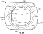
- FIG. 5C illustrates a bottom view of an anchor housing 500 , in accordance with at least one example of this disclosure.
- the anchor housing 500 can be similar to those of anchor assemblies 100 and 400 above; however, FIGS. 5A-5C show additional details of the housing 500 . FIGS. 5A-5C are discussed below concurrently.
- the housing 500 can include a proximal portion 515 , an anchor bore 516 , a distal portion 517 , a secondary bore 522 , and helical grooves 524 .
- the secondary bore 522 can include corner notches 530 a - 530 d (first angled notch 530 a , second angled notch 530 b , third angled notch 530 c , and fourth angled notch 530 d ), straight portions 532 a - 532 d , and edges 536 a - 536 g .
- axis A and orientation indicators Proximal, Distal, Medial, Lateral, Anterior, and Posterior.
- each of the corner notches 530 a - 530 d can be connected by straight portions 532 a - 532 d .
- each of straight portions 532 a - 532 d can be bevels of the secondary opening 522 , each having a substantially flat or planar face.
- the first straight portion 532 a can be connected to the first angled notch 530 a and the second angled notch 530 b
- the second straight portion 532 b can be connected to the second angled notch 530 b and the third angled notch 530 c
- the third straight portion 532 c can be connected to the third angled notch 530 c and the fourth angled notch 530 d
- the fourth straight portion 532 d can be connected to the first angled notch 530 a and the fourth corner notch 530 d.
- Each of the edges 536 a - 536 g can each be located where each of the corner notches 530 a - 530 d meets one of the straight portions 532 a - 532 d .
- the edge 536 a can be a connection between the corner notch 530 a and the straight portion 530 a ; and, the edge 536 b can be the connection between the straight portion 532 a and the corner notch 530 b .
- each of the straight portions 532 a - 532 d can be positioned relative to the corner notches 530 a - 530 d such that each of the edges 536 a - 536 g can be configured to limit or minimize engagement of the edges 536 a - 536 g with an anchor. That is, the straight portions 532 a - 532 d can be positioned to limit radially inward extension of each of the edges 536 a - 536 g from the secondary bore 522 . This can help to promote smooth movement of the anchor between the corner notches 530 a - 530 d . This can also help prevent relative movement of the anchor to the housing 500 , because the contact between the anchor and the secondary bore 522 can be relatively consistent.
- FIGS. 5A-5C also show that the helical grooves 524 can terminate near where straight portion 532 a meets corner notch 530 b and where straight portion 532 d meets corner notch 530 d (diagonally across for each other). Terminating the helical grooves 524 at these positions can help to limit interference of the helical grooves 524 with the secondary opening 522 , which can help to simplify manufacturing and can help allow for desired angulation of the anchors with respect to the housing 500 .
- the helical grooves 524 can also be placed relative to the secondary opening 5522 such that the head of the anchor can contact the helical grooves 524 to provide a sharp edge for contact with the head when the anchor is fully screwed into the bore and when the head applies a force on the housing 500 . This can help prevented relative movement of the head to the housing 500 following installation of the anchor assembly.
- FIG. 6 illustrates a bottom view of an anchor housing 600 , in accordance with at least one example of this disclosure.
- Anchor housing 600 can include a secondary bore having a substantially cloverleaf shape configured to promote relatively high angulation of an anchor relative to the housing. Any of the previously discussed anchor assembly can be modified include a secondary bore having a substantially cloverleaf shape.
- the housing 600 can include an anchor bore 616 , a distal portion 617 , and a secondary bore 622 .
- the secondary bore 622 can include corner notches 630 a - 630 d , and protrusions 632 a - 632 d . Also shown in FIG. 6 are axis A, and orientation indicators Medial, Lateral, Anterior, and Posterior.
- the housing 600 can be similar to other housing discussed above, such as housing 500 , except that secondary bore 622 of housing 600 can have a substantially cloverleaf shape. That is, the corner notches 630 a - 630 d can have a smaller radius of curvature than corner notches 530 a - 530 d , in some examples (though a larger radius can be used in other examples). Further, the corner notches 630 a - 630 d can be connected at protrusions 632 a - 632 d instead of by straight portions. This shape can provide an anchor housing that biases an anchor to extreme angulations, which can be helpful during a procedure where a desired angulation is known prior to securing the anchor housing to the bone.
- FIG. 7 illustrates a bottom view of an anchor housing 700 , in accordance with at least one example of this disclosure.
- Anchor housing 700 can include a secondary bore having a substantially cloverleaf shape configured to promote relatively high angulation of an anchor relative to the housing. Any of the previously discussed anchor assembly can be modified include a secondary bore having a substantially cloverleaf shape.
- the housing 700 can include an anchor bore 716 , a distal portion 717 , and a secondary bore 722 .
- the secondary bore 722 can include corner notches 730 a - 730 d , and protrusions 732 a - 732 d . Also shown in FIG. 7 are axis A, and orientation indicators Medial, Lateral, Anterior, and Posterior.
- the anchor housing 700 can be similar to anchor housing 600 in that secondary opening 722 of the anchor housing 700 can have a substantially clover leaf shape. However, the secondary opening 722 of the anchor housing 700 can be rotated about 90 degrees (in one example) relative to the secondary opening 622 of the housing 600 .
- This arrangement of housing 700 can provide high angulation in the anterior-posterior directions and can provide higher angulation in the lateral-medial directions, with respect to the orientation of FIG. 7 . This can translate to relatively high angulation in the interior-superior (caudal-cranial) directions and to higher angulation in the lateral-medial directions with respect to a patient.
- corner notches 730 a - 730 d of the secondary opening of the anchor housing 700 can have a relatively larger radius of curvature than the corner notches 630 a - 630 d of the housing 600 .
- the larger radius of curvature can provide different angulation of the shank relative to the housing 700 , allowing the housing 700 to be used in a larger variety of angulation applications.
- FIG. 8 illustrates a bottom view of an anchor housing 800 , in accordance with at least one example of this disclosure.
- the anchor housing 800 can include a secondary bore having a substantially diamond shape configured to promote relatively high angulation of an anchor relative to the housing in anterior, posterior, medial, and lateral directions. Any of the previously discussed anchor assembly can be modified include a secondary bore having a substantially diamond shape.
- the housing 800 can include an anchor bore 816 , a distal portion 817 , and a secondary bore 822 .
- the secondary bore 822 can include corner notches 830 a - 830 d , and straight portions 832 a - 832 d . Also shown in FIG. 8 are axis A, and orientation indicators Medial, Lateral, Anterior, and Posterior.
- the anchor housing 800 can be similar to anchor housing 500 in that the secondary opening 822 of the anchor housing 800 can have a substantially geometric shape of a square with rounded corners. However, the secondary opening 822 of the anchor housing 800 can be rotated about 90 degrees (in one example) relative to the secondary opening 522 of the housing 500 .
- This arrangement of housing 800 can provide high angulation in the anterior-posterior directions and can provide higher angulation in the lateral-medial directions with respect to the orientation of FIG. 8 . This can translate to relatively high angulation in the interior-superior (or caudal-cranial) directions and to higher angulation in the lateral-medial directions, with respect to a patient.
- the secondary opening 822 of the anchor housing 800 can also be similar to that of the anchor housing 700 , except that the secondary opening 822 of the housing 800 includes straight portions 832 a - 832 d connecting to corner notches 830 a - 830 d . This can provide relatively smooth movement of the anchor between the corner notches 830 a - 830 d.
- FIG. 9 illustrates a bottom view of an anchor housing 900 , in accordance with at least one example of this disclosure.
- Anchor housing 900 can include a secondary bore having a substantially ovalar shape configured to promote relatively high angulation of an anchor relative to the housing in medial and lateral directions. Any of the previously discussed anchor assembly can be modified include a secondary bore having a substantially ovalar shape.
- the housing 900 can include an anchor bore 916 , a distal portion 917 , and a secondary bore 922 .
- the secondary bore 922 can include corner notches 930 a and 930 b , and curved portions 932 a and 932 b . Also shown in FIG. 9 are axis A, and orientation indicators Medial, Lateral, Anterior, and Posterior.
- FIG. 9 can be similar to the other housings discussed above, except that the secondary opening 922 can have an ovalar shape. More specifically, the secondary opening 922 can include two corner notches 930 a and 930 b connected by two curved portions 932 a and 932 b .
- the corner notches 930 a and 930 b can provide relatively large angulation of an anchor with respect to the housing 900 medially-to-laterally and the curved portions 932 a and 932 b can provide less extreme angulation of the anchor superiorly-to-inferiorly with respect to the housing.
- oval can be rotated 90 degrees such that the secondary opening is configured to provide extreme angulation of the anchor with respect to the housing 900 in anterior and posterior directions with respect to the orientation of FIG. 9 , which can translate to high angulation in inferior and superior directions when the housing 900 is secured to a patient, in some procedures.
- Example 1 is an anchor assembly couplable to bone, the assembly comprising: an anchor comprising: a shank securable to bone; and a head coupled to a proximal portion of the shank; and a housing comprising: a proximal portion including an anchor bore extending distally into the housing along a longitudinal axis of the housing, the anchor bore configured to retain the head of the anchor therein; and a distal portion including a secondary bore configured to engage the anchor to limit angulation of the anchor relative to the housing, the secondary bore comprising: a first portion configured to limit the angulation of the anchor to a first angle relative to the longitudinal axis; and a plurality of second portions each configured to limit the angulation of the anchor to a second angle relative to the longitudinal axis that is greater than the first angle.
- Example 2 the subject matter of Example 1 optionally includes wherein the secondary bore is positioned at a distal end of the distal portion, and wherein the secondary bore is substantially coaxial with the anchor bore and the longitudinal axis.
- Example 3 the subject matter of any one or more of Examples 1-2 optionally include wherein each of the plurality of second portions each is configured to receive the shank therein and to create a desired angular trajectory for the shank in reference to the housing.
- Example 4 the subject matter of any one or more of Examples 1-3 optionally include wherein the secondary bore has a geometric shape substantially of a square with rounded corners from a distal perspective.
- Example 5 the subject matter of any one or more of Examples 1-4 optionally include wherein the first portion is defined by a first chafer extending radially outward from the secondary bore, wherein each of the plurality of second portions are defined by a plurality of bevels extending radially outward, and wherein each of the plurality of bevels curves along a face of each of the plurality of bevels.
- Example 6 the subject matter of any one or more of Examples 1-5 optionally include wherein the secondary bore comprises a plurality of first portions including the first portion, each of the plurality of second portions connected by the plurality of first portions.
- Example 7 the subject matter of Example 6 optionally includes wherein each of the plurality of first portions is substantially planar.
- Example 8 the subject matter of Example 7 optionally includes wherein the shank is threaded and wherein housing includes a helical groove configured to receive the threaded shank therethrough.
- Example 9 the subject matter of Example 8 optionally includes wherein the helical groove terminates substantially at connection between one of the plurality of first portions and one of the plurality of second portions.
- Example 10 the subject matter of any one or more of Examples 6-9 optionally include wherein the plurality of first portions and plurality of second portions are arranged symmetrically about a sagittal plane and a coronal plane of the housing.
- Example 11 the subject matter of any one or more of Examples 2-10 optionally include wherein the anchor further comprises a neck including a neck diameter that is smaller than a diameter of the shank and a diameter of the head, and wherein contact between the neck and the housing Is configured to limit the angulation of the anchor to the second angle relative to the longitudinal axis.
- Example 12 the subject matter of any one or more of Examples 2-11 optionally include wherein the housing includes two open sides, each open side substantially forming a U shape configured to receive a connecting member therethrough.
- Example 13 the subject matter of any one or more of Examples 1-12 optionally include the assembly further comprising: a lower piston disposable in the central bore and configured to engage the head; an upper piston disposable in the bore and configured to support a connecting member; and a biasing element disposable between the lower piston and the upper piston to bias the upper piston away from the lower piston.
- Example 14 is an anchor housing configured to receive an anchor therethrough, the anchor couplable to a bone, the anchor housing comprising: a proximal portion including an anchor bore extending distally into the housing along a longitudinal axis of the housing, the anchor bore configured to receive a shank of an anchor therethrough and configured to retain a head of the anchor therein; and a distal portion including a secondary opening configured to engage the anchor to limit angulation of the anchor relative to the housing, the secondary bore comprising: a substantially planar face configured to limit the angulation of the anchor to a first angle relative to the longitudinal axis; and an angled notch configured to limit the angulation of the anchor to a second angle relative to the longitudinal axis that is greater than the first angle.
- Example 15 the subject matter of Example 14 optionally includes wherein the distal portion further comprises a second angled notch connected to the first angled notch by the substantially planar face, the second angled notch configured to limit the angulation of the anchor to a third angle relative to the longitudinal axis that is greater than the first angle.
- Example 16 the subject matter of Example 15 optionally includes wherein the distal portion further comprises a third angled notch and a fourth angled notch, the third angled notch and the fourth angled notch configured to limit the angulation of the anchor to a third angle and a fourth angle, respectively, relative to the longitudinal axis that are greater than the first angle.
- Example 17 the subject matter of Example 16 optionally includes wherein the distal portion further comprises a second substantially planar face, a third substantially planar face, and a fourth substantially planar face, the first substantially planar face connected to the first angled notch and the second angled notch, the second substantially planar face connected to the second angled notch and the third angled notch, the third substantially planar face connected to the third angled notch and the fourth angled notch, and the fourth substantially planar face connected to the first angled notch and the fourth angled notch.
- Example 18 the subject matter of any one or more of Examples 16-17 optionally include wherein the first substantially planar face is connected to the first angled notch defining a first edge and the second angled notch is connected to the first substantially planar face defining a second edge, wherein the first substantially planar face is connected to the first angled notch and the second angled notch to limit engagement of the first edge and the second edge with the anchor.
- Example 19 the subject matter of any one or more of Examples 17-18 optionally include wherein a first segment of the first substantially planar face and a third segment of the third substantially planar face are substantially parallel, and wherein a second segment of the second substantially planar face and a fourth segment of the fourth substantially planar face are substantially parallel.
- Example 20 is an anchor housing couplable to a bone, the housing comprising: a proximal portion including an anchor bore extending distally into the housing along a longitudinal axis of the housing, the anchor bore configured to receive the shank therethrough and configured to retain the head of the anchor therein; and a distal portion including a secondary bore configured to engage the anchor to limit angulation of the anchor relative to the housing, the secondary bore comprising: a first portion configured to limit the angulation of the anchor to a first angle relative to the longitudinal axis; and a second portion configured to limit the angulation of the anchor to a second angle relative to the longitudinal axis that is greater than the first angle.
- Example 21 the systems, devices, or methods of any one or any combination of Examples 1-20 can optionally be configured such that all elements or options recited are available to use or select from.
- the terms “a” or “an” are used, as is common in patent documents, to include one or more than one, independent of any other instances or usages of “at least one” or “one or more.”
- the term “or” is used to refer to a nonexclusive or, such that “A or B” includes “A but not B,” “B but not A,” and “A and B,” unless otherwise indicated.
Landscapes
- Health & Medical Sciences (AREA)
- Orthopedic Medicine & Surgery (AREA)
- Life Sciences & Earth Sciences (AREA)
- Surgery (AREA)
- Neurology (AREA)
- Heart & Thoracic Surgery (AREA)
- Engineering & Computer Science (AREA)
- Biomedical Technology (AREA)
- Nuclear Medicine, Radiotherapy & Molecular Imaging (AREA)
- Medical Informatics (AREA)
- Molecular Biology (AREA)
- Animal Behavior & Ethology (AREA)
- General Health & Medical Sciences (AREA)
- Public Health (AREA)
- Veterinary Medicine (AREA)
- Surgical Instruments (AREA)
- Prostheses (AREA)
Abstract
Description
Claims (18)
Priority Applications (3)
| Application Number | Priority Date | Filing Date | Title |
|---|---|---|---|
| US16/550,637 US11241259B2 (en) | 2018-08-30 | 2019-08-26 | Bone anchor |
| US17/560,962 US12076056B2 (en) | 2018-08-30 | 2021-12-23 | Bone anchor |
| US18/766,311 US20250025213A1 (en) | 2018-08-30 | 2024-07-08 | Bone anchor |
Applications Claiming Priority (2)
| Application Number | Priority Date | Filing Date | Title |
|---|---|---|---|
| US201862724811P | 2018-08-30 | 2018-08-30 | |
| US16/550,637 US11241259B2 (en) | 2018-08-30 | 2019-08-26 | Bone anchor |
Related Child Applications (1)
| Application Number | Title | Priority Date | Filing Date |
|---|---|---|---|
| US17/560,962 Continuation US12076056B2 (en) | 2018-08-30 | 2021-12-23 | Bone anchor |
Publications (2)
| Publication Number | Publication Date |
|---|---|
| US20200069344A1 US20200069344A1 (en) | 2020-03-05 |
| US11241259B2 true US11241259B2 (en) | 2022-02-08 |
Family
ID=67809361
Family Applications (3)
| Application Number | Title | Priority Date | Filing Date |
|---|---|---|---|
| US16/550,637 Active 2039-09-16 US11241259B2 (en) | 2018-08-30 | 2019-08-26 | Bone anchor |
| US17/560,962 Active 2039-11-05 US12076056B2 (en) | 2018-08-30 | 2021-12-23 | Bone anchor |
| US18/766,311 Pending US20250025213A1 (en) | 2018-08-30 | 2024-07-08 | Bone anchor |
Family Applications After (2)
| Application Number | Title | Priority Date | Filing Date |
|---|---|---|---|
| US17/560,962 Active 2039-11-05 US12076056B2 (en) | 2018-08-30 | 2021-12-23 | Bone anchor |
| US18/766,311 Pending US20250025213A1 (en) | 2018-08-30 | 2024-07-08 | Bone anchor |
Country Status (3)
| Country | Link |
|---|---|
| US (3) | US11241259B2 (en) |
| EP (1) | EP3616635B1 (en) |
| ES (1) | ES2955980T3 (en) |
Cited By (1)
| Publication number | Priority date | Publication date | Assignee | Title |
|---|---|---|---|---|
| US20260033866A1 (en) * | 2007-01-26 | 2026-02-05 | Roger P. Jackson | Bone anchor receiver with intersecting horizontal and vertical tool attachment features |
Families Citing this family (5)
| Publication number | Priority date | Publication date | Assignee | Title |
|---|---|---|---|---|
| US8444681B2 (en) | 2009-06-15 | 2013-05-21 | Roger P. Jackson | Polyaxial bone anchor with pop-on shank, friction fit retainer and winged insert |
| US11241259B2 (en) | 2018-08-30 | 2022-02-08 | Zimmer Biomet Spine, Inc. | Bone anchor |
| US11559333B2 (en) | 2019-01-21 | 2023-01-24 | Zimmer Biomet Spine, Inc. | Bone anchor |
| EP3871624B1 (en) * | 2020-02-25 | 2023-07-19 | Biedermann Technologies GmbH & Co. KG | Bone anchoring device |
| DE102024124421A1 (en) * | 2024-08-27 | 2026-03-05 | Aesculap Ag | Medical screw and medical screw device |
Citations (24)
| Publication number | Priority date | Publication date | Assignee | Title |
|---|---|---|---|---|
| US20040236330A1 (en) | 2003-05-22 | 2004-11-25 | Thomas Purcell | Variable angle spinal screw assembly |
| US20050283157A1 (en) | 2004-06-17 | 2005-12-22 | Coates Bradley J | Multi-axial bone attachment assembly |
| US20070088357A1 (en) * | 2005-10-18 | 2007-04-19 | Sdgi Holdings, Inc. | Adjustable bone anchor assembly |
| US20080154315A1 (en) | 2005-02-22 | 2008-06-26 | Jackson Roger P | Polyaxial bone screw with spherical capture, compression and alignment and retention structures |
| US20080161859A1 (en) * | 2006-10-16 | 2008-07-03 | Innovative Delta Technology Llc | Bone Screw and Associated Assembly and Methods of Use Thereof |
| US7875065B2 (en) * | 2004-11-23 | 2011-01-25 | Jackson Roger P | Polyaxial bone screw with multi-part shank retainer and pressure insert |
| US20110178559A1 (en) * | 2010-01-15 | 2011-07-21 | Ebi, Llc | Uniplanar bone anchor system |
| US20110202094A1 (en) | 2009-11-11 | 2011-08-18 | Pereira Mario L | Trans-polyaxial screw |
| US20120016425A1 (en) | 2009-11-09 | 2012-01-19 | Ebi, Llc | Multiplanar bone anchor system |
| US20120059426A1 (en) * | 2008-08-01 | 2012-03-08 | Jackson Roger P | Polyaxial bone anchors with pop-on shank, friction fit fully restrained retainer, insert and tool receiving features |
| US20140257411A1 (en) | 2013-03-08 | 2014-09-11 | Warsaw Orthopedic, Inc. | Bone fastener and methods of use |
| US20150282844A1 (en) * | 2014-04-03 | 2015-10-08 | Zimmer Spine, Inc. | Uniplanar bone screw |
| US20150297266A1 (en) | 2014-04-21 | 2015-10-22 | X-Spine Systems, Inc. | Modular multi-axial screw system |
| US9168069B2 (en) * | 2009-06-15 | 2015-10-27 | Roger P. Jackson | Polyaxial bone anchor with pop-on shank and winged insert with lower skirt for engaging a friction fit retainer |
| US20160331412A1 (en) | 2015-05-12 | 2016-11-17 | Lutz Biedermann | Coupling device for coupling a rod to a bone anchoring element and bone anchoring device with such a coupling device |
| US9603630B2 (en) | 2011-04-29 | 2017-03-28 | Warsaw Orthopedic, Inc. | Rotatable base multi-axial screw assembly |
| US20170135732A1 (en) | 2013-10-29 | 2017-05-18 | Roger P. Jackson | Cervical bone anchor with collet retainer and outer locking sleeve |
| US20170245898A1 (en) | 2016-02-26 | 2017-08-31 | Warsaw Orthopedic, Inc | Spinal implant system and methods of use |
| US9763700B1 (en) * | 2016-12-14 | 2017-09-19 | Spine Wave, Inc. | Polyaxial bone screw |
| US9820782B2 (en) | 2014-06-13 | 2017-11-21 | Orthopediatrics Corp. | Bottom loaded pedicle screw |
| US20170333085A1 (en) * | 2014-06-04 | 2017-11-23 | Roger P. Jackson | Snap-on multi-planar and mono-planar receiver assemblies having integral and multi-part multipurpose positioners for pivoting and non-pivoting retainers |
| US9924971B2 (en) * | 2014-01-13 | 2018-03-27 | Biedermann Technologies Gmbh & Co. Kg | Coupling assembly for coupling a rod to a bone anchoring element, and polyaxial bone anchoring device |
| US10034691B1 (en) | 2015-12-03 | 2018-07-31 | Nuvasive, Inc. | Bone anchor |
| US20200229847A1 (en) | 2019-01-21 | 2020-07-23 | Zimmer Biomet Spine, Inc. | Bone anchor |
Family Cites Families (7)
| Publication number | Priority date | Publication date | Assignee | Title |
|---|---|---|---|---|
| US20140121703A1 (en) * | 2012-10-31 | 2014-05-01 | Roger P. Jackson | Polyaxial bone anchor with pop-on multi-thread shank, some with diametric interference fit inserts |
| WO2013043218A1 (en) * | 2009-06-15 | 2013-03-28 | Jackson Roger P | Polyaxial bone anchor with pop-on shank and winged insert with friction fit compressive collet |
| US8419778B2 (en) * | 2010-01-15 | 2013-04-16 | Ebi, Llc | Uniplanar bone anchor system |
| US9084634B1 (en) * | 2010-07-09 | 2015-07-21 | Theken Spine, Llc | Uniplanar screw |
| US8911479B2 (en) * | 2012-01-10 | 2014-12-16 | Roger P. Jackson | Multi-start closures for open implants |
| WO2019023714A1 (en) * | 2017-07-28 | 2019-01-31 | Anza Innovations Inc. | Spinal stabilization system including bottom loading wide angulation polyaxial rod anchor assemblies |
| US11241259B2 (en) | 2018-08-30 | 2022-02-08 | Zimmer Biomet Spine, Inc. | Bone anchor |
-
2019
- 2019-08-26 US US16/550,637 patent/US11241259B2/en active Active
- 2019-08-29 ES ES19194424T patent/ES2955980T3/en active Active
- 2019-08-29 EP EP19194424.8A patent/EP3616635B1/en active Active
-
2021
- 2021-12-23 US US17/560,962 patent/US12076056B2/en active Active
-
2024
- 2024-07-08 US US18/766,311 patent/US20250025213A1/en active Pending
Patent Citations (25)
| Publication number | Priority date | Publication date | Assignee | Title |
|---|---|---|---|---|
| US20040236330A1 (en) | 2003-05-22 | 2004-11-25 | Thomas Purcell | Variable angle spinal screw assembly |
| US20050283157A1 (en) | 2004-06-17 | 2005-12-22 | Coates Bradley J | Multi-axial bone attachment assembly |
| US7875065B2 (en) * | 2004-11-23 | 2011-01-25 | Jackson Roger P | Polyaxial bone screw with multi-part shank retainer and pressure insert |
| US20080154315A1 (en) | 2005-02-22 | 2008-06-26 | Jackson Roger P | Polyaxial bone screw with spherical capture, compression and alignment and retention structures |
| US20070088357A1 (en) * | 2005-10-18 | 2007-04-19 | Sdgi Holdings, Inc. | Adjustable bone anchor assembly |
| US20080161859A1 (en) * | 2006-10-16 | 2008-07-03 | Innovative Delta Technology Llc | Bone Screw and Associated Assembly and Methods of Use Thereof |
| US20120059426A1 (en) * | 2008-08-01 | 2012-03-08 | Jackson Roger P | Polyaxial bone anchors with pop-on shank, friction fit fully restrained retainer, insert and tool receiving features |
| US9168069B2 (en) * | 2009-06-15 | 2015-10-27 | Roger P. Jackson | Polyaxial bone anchor with pop-on shank and winged insert with lower skirt for engaging a friction fit retainer |
| US20120016425A1 (en) | 2009-11-09 | 2012-01-19 | Ebi, Llc | Multiplanar bone anchor system |
| US20110202094A1 (en) | 2009-11-11 | 2011-08-18 | Pereira Mario L | Trans-polyaxial screw |
| US20110178559A1 (en) * | 2010-01-15 | 2011-07-21 | Ebi, Llc | Uniplanar bone anchor system |
| US9603630B2 (en) | 2011-04-29 | 2017-03-28 | Warsaw Orthopedic, Inc. | Rotatable base multi-axial screw assembly |
| US20140257411A1 (en) | 2013-03-08 | 2014-09-11 | Warsaw Orthopedic, Inc. | Bone fastener and methods of use |
| EP2964115A1 (en) | 2013-03-08 | 2016-01-13 | Warsaw Orthopedic, Inc. | Bone fastener and methods of use |
| US20170135732A1 (en) | 2013-10-29 | 2017-05-18 | Roger P. Jackson | Cervical bone anchor with collet retainer and outer locking sleeve |
| US9924971B2 (en) * | 2014-01-13 | 2018-03-27 | Biedermann Technologies Gmbh & Co. Kg | Coupling assembly for coupling a rod to a bone anchoring element, and polyaxial bone anchoring device |
| US20150282844A1 (en) * | 2014-04-03 | 2015-10-08 | Zimmer Spine, Inc. | Uniplanar bone screw |
| US20150297266A1 (en) | 2014-04-21 | 2015-10-22 | X-Spine Systems, Inc. | Modular multi-axial screw system |
| US20170333085A1 (en) * | 2014-06-04 | 2017-11-23 | Roger P. Jackson | Snap-on multi-planar and mono-planar receiver assemblies having integral and multi-part multipurpose positioners for pivoting and non-pivoting retainers |
| US9820782B2 (en) | 2014-06-13 | 2017-11-21 | Orthopediatrics Corp. | Bottom loaded pedicle screw |
| US20160331412A1 (en) | 2015-05-12 | 2016-11-17 | Lutz Biedermann | Coupling device for coupling a rod to a bone anchoring element and bone anchoring device with such a coupling device |
| US10034691B1 (en) | 2015-12-03 | 2018-07-31 | Nuvasive, Inc. | Bone anchor |
| US20170245898A1 (en) | 2016-02-26 | 2017-08-31 | Warsaw Orthopedic, Inc | Spinal implant system and methods of use |
| US9763700B1 (en) * | 2016-12-14 | 2017-09-19 | Spine Wave, Inc. | Polyaxial bone screw |
| US20200229847A1 (en) | 2019-01-21 | 2020-07-23 | Zimmer Biomet Spine, Inc. | Bone anchor |
Non-Patent Citations (7)
| Title |
|---|
| "European Application Serial No. 19194424.8, Extended European Search Report dated Jan. 23, 2020", 10 pgs. |
| "European Application Serial No. 19194424.8, Response filed Sep. 4, 2020 to Extended European Search Report dated Jan. 23, 2020", 18 pgs. |
| "European Application Serial No. 20152733.0, Extended European Search Report dated Jun. 19, 2020", 9 pgs. |
| "European Application Serial No. 20152733.0, Response filed Jan. 22, 2021 to Extended European Search Report dated Jun. 19, 2020", 16 pgs. |
| "U.S. Appl. No. 16/694,098, Final Office Action dated Sep. 24, 2021", 11 pgs. |
| "U.S. Appl. No. 16/694,098, Non Final Office Action dated Apr. 30, 2021", 11 pgs. |
| U.S. Appl. No. 16/694,098, filed Nov. 25, 2019, Bone Anchor. |
Cited By (1)
| Publication number | Priority date | Publication date | Assignee | Title |
|---|---|---|---|---|
| US20260033866A1 (en) * | 2007-01-26 | 2026-02-05 | Roger P. Jackson | Bone anchor receiver with intersecting horizontal and vertical tool attachment features |
Also Published As
| Publication number | Publication date |
|---|---|
| US20220110663A1 (en) | 2022-04-14 |
| US20250025213A1 (en) | 2025-01-23 |
| EP3616635A1 (en) | 2020-03-04 |
| EP3616635B1 (en) | 2023-08-30 |
| US12076056B2 (en) | 2024-09-03 |
| ES2955980T3 (en) | 2023-12-11 |
| US20200069344A1 (en) | 2020-03-05 |
Similar Documents
| Publication | Publication Date | Title |
|---|---|---|
| US12076056B2 (en) | Bone anchor | |
| US11786279B2 (en) | Modular spinal fixation device | |
| EP3366240B1 (en) | Spinal implant system | |
| CN109803598B (en) | Spinal implant systems and methods | |
| EP2964115B1 (en) | Bone fastener | |
| US6533790B1 (en) | Self-guided pedical screw | |
| US9271758B2 (en) | Bone fastener and methods of use | |
| US20120035667A1 (en) | Locking mechanisms for pivoting bone anchors | |
| US9649133B2 (en) | Supplemental fixation screw | |
| US9050143B2 (en) | Spinal correction system | |
| US10363076B2 (en) | Bone fastening system | |
| US20230157728A1 (en) | Bone anchor | |
| CN112312851A (en) | Modular screw system with adjustable length | |
| CN112533553A (en) | Spinal implant system and method | |
| CN108498152A (en) | spinal implant system and method | |
| US20090240291A1 (en) | Breached pedicle screw | |
| US9757165B2 (en) | Spinal implant system and method | |
| US10736666B2 (en) | Spinal implant system and methods of use | |
| CN216455242U (en) | Spinal internal fixation system | |
| US20120116458A1 (en) | Modular pivotable screw assembly and method | |
| CN113813032A (en) | Spinal internal fixation system | |
| US10736667B2 (en) | Spinal implant system and methods of use | |
| US11109894B2 (en) | Apparatus, system, and method for spinal vertebrae stabilization |
Legal Events
| Date | Code | Title | Description |
|---|---|---|---|
| AS | Assignment |
Owner name: ZIMMER BIOMET SPINE, INC., COLORADO Free format text: ASSIGNMENT OF ASSIGNORS INTEREST;ASSIGNOR:CAPOTE, ALLISON CHRISTINE;REEL/FRAME:050164/0493 Effective date: 20190824 |
|
| FEPP | Fee payment procedure |
Free format text: ENTITY STATUS SET TO UNDISCOUNTED (ORIGINAL EVENT CODE: BIG.); ENTITY STATUS OF PATENT OWNER: LARGE ENTITY |
|
| STPP | Information on status: patent application and granting procedure in general |
Free format text: NON FINAL ACTION MAILED |
|
| STPP | Information on status: patent application and granting procedure in general |
Free format text: RESPONSE TO NON-FINAL OFFICE ACTION ENTERED AND FORWARDED TO EXAMINER |
|
| STPP | Information on status: patent application and granting procedure in general |
Free format text: FINAL REJECTION MAILED |
|
| STPP | Information on status: patent application and granting procedure in general |
Free format text: RESPONSE AFTER FINAL ACTION FORWARDED TO EXAMINER |
|
| STPP | Information on status: patent application and granting procedure in general |
Free format text: ADVISORY ACTION MAILED |
|
| STPP | Information on status: patent application and granting procedure in general |
Free format text: DOCKETED NEW CASE - READY FOR EXAMINATION |
|
| STPP | Information on status: patent application and granting procedure in general |
Free format text: NON FINAL ACTION MAILED |
|
| STPP | Information on status: patent application and granting procedure in general |
Free format text: RESPONSE TO NON-FINAL OFFICE ACTION ENTERED AND FORWARDED TO EXAMINER |
|
| STPP | Information on status: patent application and granting procedure in general |
Free format text: NOTICE OF ALLOWANCE MAILED -- APPLICATION RECEIVED IN OFFICE OF PUBLICATIONS |
|
| STPP | Information on status: patent application and granting procedure in general |
Free format text: PUBLICATIONS -- ISSUE FEE PAYMENT VERIFIED |
|
| STCF | Information on status: patent grant |
Free format text: PATENTED CASE |
|
| AS | Assignment |
Owner name: JPMORGAN CHASE BANK, N.A., AS ADMINISTRATIVE AGENT, NEW YORK Free format text: SECURITY INTEREST;ASSIGNORS:BIOMET 3I, LLC;EBI, LLC;ZIMMER BIOMET SPINE, INC.;AND OTHERS;REEL/FRAME:059293/0213 Effective date: 20220228 |
|
| AS | Assignment |
Owner name: CERBERUS BUSINESS FINANCE AGENCY, LLC, NEW YORK Free format text: GRANT OF A SECURITY INTEREST -- PATENTS;ASSIGNORS:ZIMMER BIOMET SPINE, LLC;EBI, LLC;REEL/FRAME:066970/0806 Effective date: 20240401 |
|
| AS | Assignment |
Owner name: ZIMMER BIOMET SPINE, LLC (F/K/A ZIMMER BIOMET SPINE, INC.), COLORADO Free format text: RELEASE BY SECURED PARTY;ASSIGNOR:JPMORGAN CHASE BANK, N.A.;REEL/FRAME:066973/0833 Effective date: 20240401 Owner name: EBI, LLC, NEW JERSEY Free format text: RELEASE BY SECURED PARTY;ASSIGNOR:JPMORGAN CHASE BANK, N.A.;REEL/FRAME:066973/0833 Effective date: 20240401 Owner name: EBI, LLC, NEW JERSEY Free format text: RELEASE OF SECURITY INTEREST;ASSIGNOR:JPMORGAN CHASE BANK, N.A.;REEL/FRAME:066973/0833 Effective date: 20240401 Owner name: ZIMMER BIOMET SPINE, LLC (F/K/A ZIMMER BIOMET SPINE, INC.), COLORADO Free format text: RELEASE OF SECURITY INTEREST;ASSIGNOR:JPMORGAN CHASE BANK, N.A.;REEL/FRAME:066973/0833 Effective date: 20240401 |
|
| AS | Assignment |
Owner name: ZIMMER BIOMET SPINE, LLC, COLORADO Free format text: CHANGE OF NAME;ASSIGNOR:ZIMMER BIOMET SPINE, INC.;REEL/FRAME:069772/0121 Effective date: 20240220 Owner name: HIGHRIDGE MEDICAL, LLC, COLORADO Free format text: CHANGE OF NAME;ASSIGNOR:ZIMMER BIOMET SPINE, LLC;REEL/FRAME:069772/0248 Effective date: 20240405 |
|
| MAFP | Maintenance fee payment |
Free format text: PAYMENT OF MAINTENANCE FEE, 4TH YEAR, LARGE ENTITY (ORIGINAL EVENT CODE: M1551); ENTITY STATUS OF PATENT OWNER: LARGE ENTITY Year of fee payment: 4 |