US11237239B2 - Magnetic resonance cest imaging sequence and device based on frequency stabilization module - Google Patents
Magnetic resonance cest imaging sequence and device based on frequency stabilization module Download PDFInfo
- Publication number
- US11237239B2 US11237239B2 US16/762,917 US201916762917A US11237239B2 US 11237239 B2 US11237239 B2 US 11237239B2 US 201916762917 A US201916762917 A US 201916762917A US 11237239 B2 US11237239 B2 US 11237239B2
- Authority
- US
- United States
- Prior art keywords
- phase
- line
- encoded
- space data
- estimated value
- Prior art date
- Legal status (The legal status is an assumption and is not a legal conclusion. Google has not performed a legal analysis and makes no representation as to the accuracy of the status listed.)
- Active
Links
Images


Classifications
-
- G—PHYSICS
- G01—MEASURING; TESTING
- G01R—MEASURING ELECTRIC VARIABLES; MEASURING MAGNETIC VARIABLES
- G01R33/00—Arrangements or instruments for measuring magnetic variables
- G01R33/20—Arrangements or instruments for measuring magnetic variables involving magnetic resonance
- G01R33/44—Arrangements or instruments for measuring magnetic variables involving magnetic resonance using nuclear magnetic resonance [NMR]
- G01R33/46—NMR spectroscopy
- G01R33/4616—NMR spectroscopy using specific RF pulses or specific modulation schemes, e.g. stochastic excitation, adiabatic RF pulses, composite pulses, binomial pulses, Shinnar-le-Roux pulses, spectrally selective pulses not being used for spatial selection
-
- G—PHYSICS
- G01—MEASURING; TESTING
- G01R—MEASURING ELECTRIC VARIABLES; MEASURING MAGNETIC VARIABLES
- G01R33/00—Arrangements or instruments for measuring magnetic variables
- G01R33/20—Arrangements or instruments for measuring magnetic variables involving magnetic resonance
- G01R33/44—Arrangements or instruments for measuring magnetic variables involving magnetic resonance using nuclear magnetic resonance [NMR]
- G01R33/48—NMR imaging systems
- G01R33/483—NMR imaging systems with selection of signals or spectra from particular regions of the volume, e.g. in vivo spectroscopy
- G01R33/485—NMR imaging systems with selection of signals or spectra from particular regions of the volume, e.g. in vivo spectroscopy based on chemical shift information [CSI] or spectroscopic imaging, e.g. to acquire the spatial distributions of metabolites
-
- G—PHYSICS
- G01—MEASURING; TESTING
- G01R—MEASURING ELECTRIC VARIABLES; MEASURING MAGNETIC VARIABLES
- G01R33/00—Arrangements or instruments for measuring magnetic variables
- G01R33/20—Arrangements or instruments for measuring magnetic variables involving magnetic resonance
- G01R33/44—Arrangements or instruments for measuring magnetic variables involving magnetic resonance using nuclear magnetic resonance [NMR]
- G01R33/48—NMR imaging systems
- G01R33/58—Calibration of imaging systems, e.g. using test probes, Phantoms; Calibration objects or fiducial markers such as active or passive RF coils surrounding an MR active material
- G01R33/583—Calibration of signal excitation or detection systems, e.g. for optimal RF excitation power or frequency
-
- A—HUMAN NECESSITIES
- A61—MEDICAL OR VETERINARY SCIENCE; HYGIENE
- A61B—DIAGNOSIS; SURGERY; IDENTIFICATION
- A61B5/00—Measuring for diagnostic purposes; Identification of persons
- A61B5/05—Detecting, measuring or recording for diagnosis by means of electric currents or magnetic fields; Measuring using microwaves or radio waves
- A61B5/055—Detecting, measuring or recording for diagnosis by means of electric currents or magnetic fields; Measuring using microwaves or radio waves involving electronic [EMR] or nuclear [NMR] magnetic resonance, e.g. magnetic resonance imaging
-
- G—PHYSICS
- G01—MEASURING; TESTING
- G01R—MEASURING ELECTRIC VARIABLES; MEASURING MAGNETIC VARIABLES
- G01R33/00—Arrangements or instruments for measuring magnetic variables
- G01R33/20—Arrangements or instruments for measuring magnetic variables involving magnetic resonance
- G01R33/44—Arrangements or instruments for measuring magnetic variables involving magnetic resonance using nuclear magnetic resonance [NMR]
- G01R33/46—NMR spectroscopy
- G01R33/465—NMR spectroscopy applied to biological material, e.g. in vitro testing
-
- G—PHYSICS
- G01—MEASURING; TESTING
- G01R—MEASURING ELECTRIC VARIABLES; MEASURING MAGNETIC VARIABLES
- G01R33/00—Arrangements or instruments for measuring magnetic variables
- G01R33/20—Arrangements or instruments for measuring magnetic variables involving magnetic resonance
- G01R33/44—Arrangements or instruments for measuring magnetic variables involving magnetic resonance using nuclear magnetic resonance [NMR]
- G01R33/48—NMR imaging systems
- G01R33/54—Signal processing systems, e.g. using pulse sequences ; Generation or control of pulse sequences; Operator console
- G01R33/543—Control of the operation of the MR system, e.g. setting of acquisition parameters prior to or during MR data acquisition, dynamic shimming, use of one or more scout images for scan plane prescription
-
- G—PHYSICS
- G01—MEASURING; TESTING
- G01R—MEASURING ELECTRIC VARIABLES; MEASURING MAGNETIC VARIABLES
- G01R33/00—Arrangements or instruments for measuring magnetic variables
- G01R33/20—Arrangements or instruments for measuring magnetic variables involving magnetic resonance
- G01R33/44—Arrangements or instruments for measuring magnetic variables involving magnetic resonance using nuclear magnetic resonance [NMR]
- G01R33/48—NMR imaging systems
- G01R33/54—Signal processing systems, e.g. using pulse sequences ; Generation or control of pulse sequences; Operator console
- G01R33/56—Image enhancement or correction, e.g. subtraction or averaging techniques, e.g. improvement of signal-to-noise ratio and resolution
- G01R33/5605—Image enhancement or correction, e.g. subtraction or averaging techniques, e.g. improvement of signal-to-noise ratio and resolution by transferring coherence or polarization from a spin species to another, e.g. creating magnetization transfer contrast [MTC], polarization transfer using nuclear Overhauser enhancement [NOE]
-
- G—PHYSICS
- G01—MEASURING; TESTING
- G01R—MEASURING ELECTRIC VARIABLES; MEASURING MAGNETIC VARIABLES
- G01R33/00—Arrangements or instruments for measuring magnetic variables
- G01R33/20—Arrangements or instruments for measuring magnetic variables involving magnetic resonance
- G01R33/44—Arrangements or instruments for measuring magnetic variables involving magnetic resonance using nuclear magnetic resonance [NMR]
- G01R33/48—NMR imaging systems
- G01R33/54—Signal processing systems, e.g. using pulse sequences ; Generation or control of pulse sequences; Operator console
- G01R33/56—Image enhancement or correction, e.g. subtraction or averaging techniques, e.g. improvement of signal-to-noise ratio and resolution
- G01R33/565—Correction of image distortions, e.g. due to magnetic field inhomogeneities
- G01R33/56563—Correction of image distortions, e.g. due to magnetic field inhomogeneities caused by a distortion of the main magnetic field B0, e.g. temporal variation of the magnitude or spatial inhomogeneity of B0
-
- G—PHYSICS
- G01—MEASURING; TESTING
- G01R—MEASURING ELECTRIC VARIABLES; MEASURING MAGNETIC VARIABLES
- G01R33/00—Arrangements or instruments for measuring magnetic variables
- G01R33/20—Arrangements or instruments for measuring magnetic variables involving magnetic resonance
- G01R33/44—Arrangements or instruments for measuring magnetic variables involving magnetic resonance using nuclear magnetic resonance [NMR]
- G01R33/48—NMR imaging systems
- G01R33/54—Signal processing systems, e.g. using pulse sequences ; Generation or control of pulse sequences; Operator console
- G01R33/56—Image enhancement or correction, e.g. subtraction or averaging techniques, e.g. improvement of signal-to-noise ratio and resolution
- G01R33/5607—Image enhancement or correction, e.g. subtraction or averaging techniques, e.g. improvement of signal-to-noise ratio and resolution by reducing the NMR signal of a particular spin species, e.g. of a chemical species for fat suppression, or of a moving spin species for black-blood imaging
Definitions
- the present disclosure relates to the field of magnetic resonance technology, and in particular, to the field of a correction of a frequency shift in the magnetic resonance CEST imaging.
- Magnetic resonance CEST (Chemical Exchange Saturation Transfer) imaging is an important molecular magnetic resonance imaging technology and can detect free proteins and peptides in endogenous cytoplasm in a living body.
- the magnetic resonance CEST imaging is also used for tumor detection and tumor classification since it can obtain information on overexpressed proteins and peptides in the glioma.
- the magnetic resonance CEST imaging is very sensitive to the frequency drift of the main magnetic field, so that if the frequency drift of the main magnetic field is not corrected, it will greatly affect the performance of the magnetic resonance CEST imaging. Based on the interference of the frequency drift of the main magnetic field on the performance of the magnetic resonance CEST imaging, some researchers have proposed a method to correct the frequency drift of the main magnetic field in data post-processing.
- a magnetic resonance CEST imaging sequence based on a frequency stabilization module can not only correct the frequency drift of the main magnetic field in real time but can also effectively suppress the fat signals, thereby improving the performance of the magnetic resonance CEST imaging.
- An object of the present disclosure is to provide a magnetic resonance CEST imaging sequence based on a frequency stabilization module, to achieve the real-time correction of the frequency drift of the main magnetic field and ensure effective suppression on the fat signals, so as to improve the performance of the magnetic resonance CEST imaging.
- a magnetic resonance CEST imaging sequence based on a frequency stabilization module includes following steps:
- Step 1 in the frequency stabilization module, exciting a target slice with a radio frequency pulse having a flip angle smaller than 90°, and collecting three lines of non-phase-encoded k-space data at three different moments t 1 , t 2 , and t 3 , respectively, where t 2 ⁇ t 1 ⁇ t 3 ⁇ t 2 ⁇ 2(t 2 ⁇ t 1 );
- Step 2 obtaining a fine estimated value of a main magnetic field frequency drift by calculating a phase difference between a first line of non-phase-encoded k-space data and a second line of non-phase encoded k-space data;
- Step 3 obtaining a coarse estimated value of the main magnetic field frequency drift by calculating a difference between a phase difference between the second line of non-phase encoded k-space data and a third line of non-phase encoded k-space data and the phase difference between the first line of non-phase-encoded k-space data and the second line of non-phase encoded k-space data;
- Step 4 comparing a difference between the coarse estimated value and the fine estimated value with a threshold, and if the difference between the coarse estimated value and the fine estimated value is smaller than the threshold, then selecting the fine estimated value as a value of the main magnetic field frequency drift; otherwise, selecting the coarse estimated value as the value of the main magnetic field frequency drift;
- Step 5 adjusting a center frequency of the radio frequency pulse based on the value of the main magnetic field frequency drift, and then performing magnetic resonance CEST imaging based on the adjusted center frequency of the radio frequency pulse.
- Step 2 the fine estimated value is calculated by:
- ⁇ TE 2-1 is an interval between the moments t 1 and t 2
- ⁇ 2-1 is the phase difference between the first line of non-phase encoded k-space data and the second line of the non-phase encoded k-space data and is calculated based on:
- ⁇ i 2-1 is a phase difference between an i th data sampling point in the first line of non-phase encoded k-space data and an i th data sampling point in the second line of the non-phase encoded k-space data
- n is a number of sampling points in each line of non-phase encoded k-space data.
- Step 3 the coarse estimated value is calculated by:
- ⁇ ⁇ ⁇ f coarse ⁇ ⁇ 3 - 2 - ⁇ ⁇ 2 - 1 2 ⁇ ⁇ ⁇ ⁇ ,
- ⁇ i 3-2 is a phase difference between the i th data sampling point in the second line of non-phase encoded k-space data and an i th data sampling point in the third line of non-phase encoded k-space data.
- Step 4 the value of the main magnetic field frequency drift is determined by:
- the flip angle in the Step 1 is preferably smaller than 10°.
- Another object of the present disclosure is to provide a magnetic resonance CEST imaging device based on a frequency stabilization module, including a frequency stabilization module and a CEST imaging module;
- the frequency stabilization module is configured to perform Step 1 through Step 5,
- Step 1 in the frequency stabilization module, exciting a target slice with a radio frequency pulse having a flip angle smaller than 90°, and collecting three lines of non-phase-encoded k-space data at three different moments t 1 , t 2 , and t 3 , respectively, where t 2 ⁇ t 1 ⁇ t 3 ⁇ t 2 ⁇ 2(t 2 ⁇ t 1 );
- Step 2 obtaining a fine estimated value of a main magnetic field frequency drift by calculating a phase difference between a first line of non-phase-encoded k-space data and a second line of non-phase encoded k-space data;
- Step 3 obtaining a coarse estimated value of the main magnetic field frequency drift by calculating a difference between a phase difference between the second line of non-phase encoded k-space data and a third line of non-phase encoded k-space data and the phase difference between the first line of non-phase-encoded k-space data and the second line of non-phase encoded k-space data;
- Step 4 comparing a difference between the coarse estimated value and the fine estimated value of the main magnetic field frequency drift with a threshold, and if the difference between the coarse estimated value and the fine estimated value is smaller than the threshold, then selecting the fine estimated value as a value of the main magnetic field frequency drift; otherwise, selecting the coarse estimated value as the value of the main magnetic field frequency drift; and
- Step 5 adjusting a center frequency of the radio frequency pulse based on the value of the main magnetic field frequency drift, and then performing magnetic resonance CEST imaging based on the adjusted center frequency of the radio frequency pulse.
- the magnetic resonance CEST imaging in the Step 5 can adopt conventional magnetic resonance CEST imaging.
- the conventional magnetic resonance CEST imaging sequence includes three modules: CEST saturation, spectral presaturation with inversion recovery fat suppression, and turbo spin echo acquisition.
- the fine estimated value in the Step 2 is calculated by:
- ⁇ TE 2-1 is an interval between the moments t 1 and t 2
- ⁇ 2-1 is the phase difference between the first line of non-phase encoded k-space data and the second line of the non-phase encoded k-space data and is calculated based on:
- ( ⁇ i 2-1 is a phase difference between an i th data sampling point in the first line of non-phase encoded k-space data and an i th data sampling point in the second line of the non-phase encoded k-space data
- n is a number of sampling points in each line of non-phase encoded k-space data.
- the coarse estimated value is calculated by:
- ⁇ ⁇ ⁇ f coarse ⁇ ⁇ 3 - 2 - ⁇ ⁇ 2 - 1 2 ⁇ ⁇ ⁇ ⁇ ,
- ⁇ i 3-2 is a phase difference between the i th data sampling point in the second line of non-phase encoded k-space data and an i th data sampling point in the third line of non-phase encoded k-space data.
- the value of the main magnetic field frequency drift in the Step 4 is determined by:
- the flip angle in the Step 1 is preferably smaller than 10°.
- the present disclosure has the following beneficial effects.
- the present disclosure by collecting three lines of non-phase-encoded k-space data in the frequency stabilization module and calculating the phase difference between lines of non-phase-encoded k-space data, obtains the coarse estimated value and the fine estimated value of the main magnetic field frequency drift through the relationship between the phase and the frequency, and removes an effect of the 2 ⁇ periodicity of the phase by comparing the difference between the coarse estimated value and the fine estimated value of the main magnetic field frequency drift with the threshold, so as to obtain an accurate value of the main magnetic field frequency drift.
- the center frequency of the radio frequency pulse is then adjusted according to the calculation result of the main magnetic field frequency drift, which can not only effectively suppress fat signals but also correct the main magnetic field frequency drift in real time, to improve the performance of magnetic resonance CEST imaging and provide the reliability of precision of the subsequent quantitative analysis of CEST signals, which also makes the present disclosure have very important clinical application value.
- FIG. 1 is a block diagram of a magnetic resonance CEST imaging sequence based on a frequency stabilization module.
- FIG. 2 illustrates comparison of CEST images respectively obtained through a magnetic resonance CEST imaging sequence based on a frequency stabilization module and through a conventional magnetic resonance CEST imaging sequence without a frequency stabilization module when scanning a water phantom experiment.
- FIG. 3 illustrates comparison of CEST images respectively obtained through a magnetic resonance CEST imaging sequence based on a frequency stabilization module and through a conventional magnetic resonance CEST imaging sequence without a frequency stabilization module when scanning a human brain.
- FIG. 4 illustrates comparison of average CEST values of regions of interest on CEST images respectively obtained through a magnetic resonance CEST imaging sequence based on a frequency stabilization module and through a conventional magnetic resonance CEST imaging sequence without a frequency stabilization module when scanning a human brain.
- a preferred embodiment of the present disclosure provides a magnetic resonance CEST imaging sequence based on a frequency stabilization module.
- the method includes the following steps.
- a target slice is excited with a radio frequency pulse having a small flip angle smaller than 90° (preferably smaller than 10°), and three lines of non-phase-encoded k-space data are collected at moments t 1 , t 2 , and t 3 , respectively, where the moments t 1 , t 2 , and t 3 need to satisfy: t 2 ⁇ t 1 ⁇ t 3 -t 2 ⁇ 2(t 2 ⁇ t 1 ).
- Step 2 first, phase differences between individual data sampling points in the first line of non-phase-encoded k-space data and individual data sampling points in the second line of non-phase-encoded k-space data are averaged to obtain the phase difference between the first lines of non-phase-encoded k-space data and the second line of non-phase-encoded k-space data, and then a fine estimated value of main magnetic field frequency drift is calculated based on a relationship between a phase and a frequency and is calculated based on:
- ⁇ i 2-1 is a phase difference between the i th data sampling point in the first line of non-phase encoded k-space data and the i th data sampling point in the second line of the non-phase encoded k-space data
- n is the number of sampling points in each line of non-phase encoded space data
- ⁇ 2-1 is the phase difference between the first line of non-phase encoded k-space data and the second line of the non-phase encoded k-space data
- ⁇ TE 2-1 is an interval between the moments t 1 and t 2
- ⁇ f fine is the fine estimated value of the main magnetic field frequency drift.
- Step 3 a difference between the phase difference between the second line of non-phase encoded k-space data and the third line of non-phase encoded k-space data and the phase difference between the first line of non-phase-encoded k-space data and the second line of non-phase encoded k-space data is calculated, and a coarse estimated value of the main magnetic field frequency drift is obtained.
- ⁇ ⁇ ⁇ f coarse ⁇ _ 3 - 2 - ⁇ _ 2 - 1 2 ⁇ ⁇ ⁇ ⁇ ( 5 )
- ⁇ 2-1 is the phase difference between the first line of non-phase encoded k-space data and the second line of the non-phase encoded k-space data
- ⁇ TE 2-1 is an interval between the moments t 1 and t 2
- ⁇ TE 3-2 is an interval between the moments t 2 and t 3
- ⁇ is a blank interval between the moments t 2 and t 3
- ⁇ f coarse is the coarse estimated value of the main magnetic field frequency drift
- ⁇ 3-2 is the phase difference between the second line of non-phase encoded k-space data and the third line of non-phase encoded k-space data is calculated similarly to ⁇ 2-1 as:
- ⁇ i 3-2 is a phase difference between the i th data sampling point in the second line of non-phase encoded k-space data and an i th data sampling point in the third line of non-phase encoded k-space data.
- Step 4 due to 2 ⁇ periodicity of the phase, in order to remove an effect of the 2 ⁇ periodicity of the phase, it is necessary to compare a difference between the coarse estimated value and the fine estimated value of the main magnetic field frequency drift with a threshold, and the threshold is a maximum value of the main magnetic field frequency drift in a fine estimation range. Details are as follows.
- a calculation process of the threshold f threshold is as follows:
- ⁇ f fine is the fine estimated value of the main magnetic field frequency drift
- ⁇ f coarse is the coarse estimated value of the main magnetic field frequency drift
- f threshold is the threshold
- ⁇ f is the value of the main magnetic field frequency drift
- a center frequency of the radio frequency pulse is adjusted according to the calculated value of the main magnetic field frequency drift, to ensure effective suppression of fat signals and correct the main magnetic field frequency drift in real time.
- magnetic resonance CEST imaging can be performed according to the adjusted center frequency of the radio frequency pulse.
- the magnetic resonance CEST imaging here can adopt conventional magnetic resonance CEST imaging, and it will be briefly introduced since it is not a focus of the present disclosure.
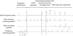
- a conventional magnetic resonance CEST imaging sequence includes three modules, i.e., CEST saturation, spectral presaturation with inversion recovery fat suppression, and turbo spin echo acquisition:
- the CEST saturation module including four rectangular saturation pulses, each of the saturation pulses being immediately followed by one spoiler gradient;
- the spectral presaturation with inversion recovery fat suppression module including one radio frequency pulse having a flip angle greater than 90 degrees, the radio frequency pulse being followed by one spoiler gradient;
- the turbo spin echo acquisition module including one radio frequency pulse that excites a target slice, and the radio frequency pulse being followed by m refocusing radio frequency pulses; that is, m lines of k-space data are collected in each repetition period (m is an acceleration factor); when each of the refocusing radio frequency pulses is applied, slice selection gradient encoding is performed at the same time, then phase gradient encoding is performed, finally frequency gradient encoding is performed, and k-space data acquisition is performed while performing the frequency gradient encoding.
- the magnetic resonance CEST imaging method based on the frequency stabilization module of the present disclosure calculates the main magnetic field frequency drift through collecting three lines of non-phase-encoded k-space data, and then adjusts the center frequency of the radio frequency pulse according to the value of the main magnetic field frequency drift, to correct the main magnetic field frequency drift in real time, thereby improving the performance of the magnetic resonance CEST imaging.
- the blank interval ⁇ satisfies ⁇ 0 according to its definition, and its actual value can also be 0.
- f threshold ⁇
- a magnetic resonance CEST imaging device based on a frequency stabilization module can also be provided, and the device includes a frequency stabilization module and a CEST imaging module.
- the frequency stabilization module is configured to perform Step 1 through Step 5, to correct the main magnetic field frequency drift and ensure effective suppression of fat signals.
- the CEST imaging module is configured to be responsible for performing conventional magnetic resonance CEST imaging based on the adjusted center frequency of the radio frequency pulse.
- the above magnetic resonance CEST imaging sequence based on the frequency stabilization module was respectively tested in magnetic resonance CEST imaging experiments of a water phantom and of 26 tested brains, and the results are compared with results of the conventional magnetic resonance CEST imaging sequence, to which the frequency stabilization module is not applied, respectively tested in magnetic resonance CEST imaging experiments of the water phantom and of the tested brains.
- Step 1 through Step 5 which will not be repeated herein, and hereafter only specific parameters are introduced in the following.
- f threshold 387.60 Hz.
- the three modules of the conventional magnetic resonance CEST imaging sequence are as follows:
- the CEST saturation module includes four rectangular saturation pulses, and each of the saturation pulses has a duration of 200 ms and an amplitude of 2 ⁇ T; each of the saturation pulses is followed by one spoiler gradient, and the spoiler gradient has a duration of 10 ms and intensity of 10 mT/m;
- this module includes one radio frequency pulse having a 110-degree flip angle, and the radio frequency is followed by one spoiler gradient;
- this module includes one radio frequency pulse having a 90-degree flip angle, and the 90-degree radio frequency pulse is followed by 42180-degree refocused radio frequency pulses; that is, 42 lines of k-space data are collected in each repetition period (the acceleration factor is 42); when each of the 180-degree refocusing radio frequency pulse is applied, slice selection gradient encoding is performed at the same time, then phase gradient encoding is performed, finally frequency gradient encoding is performed, and k-space data acquisition is performed while performing the frequency gradient encoding.
- the CEST image quality of the magnetic resonance CEST imaging sequence based on the frequency stabilization module is very good; while on the CEST image of the conventional magnetic resonance CEST imaging sequence to which the frequency stabilization module is not applied, there are a lot of image artifacts caused by the main magnetic field frequency drift, resulting in that the image quality is relatively poor and the CEST image intensity changes drastically, which shows the effectiveness of the present disclosure.
- the average CEST value of a region of interest of the CEST image of the magnetic resonance CEST imaging sequence based on the frequency stabilization module is very stable, while the average CEST value of a region of interest of the CEST image of an experiment in which the human brain is scanned by the conventional magnetic resonance CEST imaging sequence to which the frequency stabilization module is not applied has a relatively large fluctuation, which further proves the effectiveness of the present disclosure.
Landscapes
- Physics & Mathematics (AREA)
- High Energy & Nuclear Physics (AREA)
- Condensed Matter Physics & Semiconductors (AREA)
- General Physics & Mathematics (AREA)
- Health & Medical Sciences (AREA)
- Engineering & Computer Science (AREA)
- Signal Processing (AREA)
- General Health & Medical Sciences (AREA)
- Nuclear Medicine, Radiotherapy & Molecular Imaging (AREA)
- Radiology & Medical Imaging (AREA)
- Spectroscopy & Molecular Physics (AREA)
- Life Sciences & Earth Sciences (AREA)
- Molecular Biology (AREA)
- Optics & Photonics (AREA)
- Biophysics (AREA)
- Pathology (AREA)
- Biomedical Technology (AREA)
- Heart & Thoracic Surgery (AREA)
- Medical Informatics (AREA)
- Surgery (AREA)
- Animal Behavior & Ethology (AREA)
- Public Health (AREA)
- Veterinary Medicine (AREA)
- Magnetic Resonance Imaging Apparatus (AREA)
Abstract
Description
Claims (4)
Applications Claiming Priority (3)
| Application Number | Priority Date | Filing Date | Title |
|---|---|---|---|
| CN201811210428.3A CN109521383B (en) | 2018-10-17 | 2018-10-17 | A magnetic resonance CEST imaging sequence and device based on a frequency stabilization module |
| CN201811210428.3 | 2018-10-17 | ||
| PCT/CN2019/104183 WO2020078131A1 (en) | 2018-10-17 | 2019-09-03 | Magnetic resonance cest imaging sequence and apparatus based on frequency stabilization module |
Publications (2)
| Publication Number | Publication Date |
|---|---|
| US20210373100A1 US20210373100A1 (en) | 2021-12-02 |
| US11237239B2 true US11237239B2 (en) | 2022-02-01 |
Family
ID=65770179
Family Applications (1)
| Application Number | Title | Priority Date | Filing Date |
|---|---|---|---|
| US16/762,917 Active US11237239B2 (en) | 2018-10-17 | 2019-09-03 | Magnetic resonance cest imaging sequence and device based on frequency stabilization module |
Country Status (4)
| Country | Link |
|---|---|
| US (1) | US11237239B2 (en) |
| JP (1) | JP6941232B2 (en) |
| CN (1) | CN109521383B (en) |
| WO (1) | WO2020078131A1 (en) |
Families Citing this family (10)
| Publication number | Priority date | Publication date | Assignee | Title |
|---|---|---|---|---|
| CN109521383B (en) | 2018-10-17 | 2019-08-30 | 浙江大学 | A magnetic resonance CEST imaging sequence and device based on a frequency stabilization module |
| CN111722167B (en) * | 2019-03-19 | 2021-07-30 | 浙江大学 | Chemical exchange saturation transfer-magnetic resonance imaging CEST-MRI sequence generation method, device and readable storage medium |
| CN109998548B (en) * | 2019-04-17 | 2020-09-18 | 清华大学 | Quantitative myocardial magnetic resonance imaging method, equipment and storage medium |
| JP7308097B2 (en) * | 2019-08-20 | 2023-07-13 | キヤノンメディカルシステムズ株式会社 | METHOD OF SETTING EXCITATION AREA AND MAGNETIC RESONANCE IMAGING DEVICE |
| CN112904251B (en) * | 2020-03-31 | 2022-04-29 | 浙江大学 | Magnetic resonance CEST imaging frequency drift correction method, device, medium and imaging equipment |
| CN111521629B (en) * | 2020-04-30 | 2022-08-12 | 中国科学院精密测量科学与技术创新研究院 | A Magnetic Resonance Imaging Method for Non-uniform Saturation Energy Distribution for Quantitative Measurement of pH |
| US11366189B2 (en) | 2020-09-25 | 2022-06-21 | Uih America, Inc. | Systems and methods for magnetic resonance imaging |
| CN112331259B (en) * | 2020-11-26 | 2024-04-12 | 浙江大学 | Tissue metabolite information evaluation method, device and medium based on Bloch-McConnell equation simulation |
| CN112731235B (en) * | 2020-12-09 | 2024-04-19 | 中国科学院深圳先进技术研究院 | Magnetic resonance chemical exchange saturation transfer imaging method and related equipment |
| EP4597147A1 (en) | 2024-02-01 | 2025-08-06 | Koninklijke Philips N.V. | Cest imaging with variable flip angle |
Citations (11)
| Publication number | Priority date | Publication date | Assignee | Title |
|---|---|---|---|---|
| WO1995030908A1 (en) | 1994-05-09 | 1995-11-16 | Siemens Aktiengesellschaft | Reconstruction of images from mr signals in inhomogenous magnetic fields |
| CN1378817A (en) | 2001-04-04 | 2002-11-13 | Ge医疗系统环球技术有限公司 | Method for correcting resonance frequency change and magnetic resonance imaging equipment |
| US20060164083A1 (en) * | 2003-07-07 | 2006-07-27 | Harvey Paul R | Method of monitoring a magnetic field drift of a magnetic resonance imaging apparatus |
| CN101357063A (en) | 2008-08-29 | 2009-02-04 | 华东师范大学 | A magnetic resonance fast spin echo imaging method |
| US20090256567A1 (en) | 2008-04-10 | 2009-10-15 | Pelin Aksit | Three-point method and system for fast and robust field mapping for epi geometric distortion correction |
| CN102697501A (en) | 2011-03-28 | 2012-10-03 | 西门子公司 | Magnetic resonance method and system to correct phase information in mr images |
| US20140117987A1 (en) * | 2011-10-13 | 2014-05-01 | Toshiba Medical Systems Corporation | Magnetic resonance imaging apparatus and magnetic resonance imaging method |
| WO2014199879A1 (en) | 2013-06-14 | 2014-12-18 | 株式会社東芝 | Magnetic resonance imaging device, and magnetic resonance imaging method |
| JP2015016333A (en) | 2013-07-11 | 2015-01-29 | シーメンス アクチエンゲゼルシヤフトSiemens Aktiengesellschaft | Method for obtaining B0 magnetic field map by magnetic resonance apparatus and magnetic resonance apparatus |
| JP2015512317A (en) | 2012-04-03 | 2015-04-27 | コーニンクレッカ フィリップス エヌ ヴェ | MR imaging using APT contrast enhancement and sampling at multiple echo times |
| CN109521383A (en) | 2018-10-17 | 2019-03-26 | 浙江大学 | A kind of magnetic resonance CEST imaging sequence and device based on frequency stabilization module |
Family Cites Families (3)
| Publication number | Priority date | Publication date | Assignee | Title |
|---|---|---|---|---|
| DE102012208425B4 (en) * | 2012-05-21 | 2013-12-12 | Siemens Aktiengesellschaft | Continuously correct phase errors of a multidimensional, site-selective magnetic resonance measurement sequence |
| DE102013205930B4 (en) * | 2013-04-04 | 2014-11-20 | Siemens Aktiengesellschaft | Determination of a resonance frequency deviation with spatially distorted slice excitation |
| CN105759233B (en) * | 2016-03-04 | 2018-09-25 | 深圳先进技术研究院 | A kind of rapid chemical exchanges saturation transfer imaging method and system |
-
2018
- 2018-10-17 CN CN201811210428.3A patent/CN109521383B/en active Active
-
2019
- 2019-09-03 JP JP2020522811A patent/JP6941232B2/en active Active
- 2019-09-03 US US16/762,917 patent/US11237239B2/en active Active
- 2019-09-03 WO PCT/CN2019/104183 patent/WO2020078131A1/en not_active Ceased
Patent Citations (13)
| Publication number | Priority date | Publication date | Assignee | Title |
|---|---|---|---|---|
| WO1995030908A1 (en) | 1994-05-09 | 1995-11-16 | Siemens Aktiengesellschaft | Reconstruction of images from mr signals in inhomogenous magnetic fields |
| CN1378817A (en) | 2001-04-04 | 2002-11-13 | Ge医疗系统环球技术有限公司 | Method for correcting resonance frequency change and magnetic resonance imaging equipment |
| US20060164083A1 (en) * | 2003-07-07 | 2006-07-27 | Harvey Paul R | Method of monitoring a magnetic field drift of a magnetic resonance imaging apparatus |
| CN1816754A (en) | 2003-07-07 | 2006-08-09 | 皇家飞利浦电子股份有限公司 | A method of monitoring a magnetic field drift of a magnetic resonance imaging apparatus |
| JP2007526787A (en) | 2003-07-07 | 2007-09-20 | コーニンクレッカ フィリップス エレクトロニクス エヌ ヴィ | Method for monitoring magnetic field drift of magnetic resonance imaging apparatus |
| US20090256567A1 (en) | 2008-04-10 | 2009-10-15 | Pelin Aksit | Three-point method and system for fast and robust field mapping for epi geometric distortion correction |
| CN101357063A (en) | 2008-08-29 | 2009-02-04 | 华东师范大学 | A magnetic resonance fast spin echo imaging method |
| CN102697501A (en) | 2011-03-28 | 2012-10-03 | 西门子公司 | Magnetic resonance method and system to correct phase information in mr images |
| US20140117987A1 (en) * | 2011-10-13 | 2014-05-01 | Toshiba Medical Systems Corporation | Magnetic resonance imaging apparatus and magnetic resonance imaging method |
| JP2015512317A (en) | 2012-04-03 | 2015-04-27 | コーニンクレッカ フィリップス エヌ ヴェ | MR imaging using APT contrast enhancement and sampling at multiple echo times |
| WO2014199879A1 (en) | 2013-06-14 | 2014-12-18 | 株式会社東芝 | Magnetic resonance imaging device, and magnetic resonance imaging method |
| JP2015016333A (en) | 2013-07-11 | 2015-01-29 | シーメンス アクチエンゲゼルシヤフトSiemens Aktiengesellschaft | Method for obtaining B0 magnetic field map by magnetic resonance apparatus and magnetic resonance apparatus |
| CN109521383A (en) | 2018-10-17 | 2019-03-26 | 浙江大学 | A kind of magnetic resonance CEST imaging sequence and device based on frequency stabilization module |
Non-Patent Citations (3)
| Title |
|---|
| "Real-Time Rf Pulse Adjustment for B0 Drift Correction, Magnetic Resonance in Medicine" Thomas Benner et al. [2006] vol. 56 pp. 204-209. |
| First Office Action (2020-522811) dated May 10, 2021. |
| International Search Report (PCT/CN2019/104183); dated Dec. 9, 2019. |
Also Published As
| Publication number | Publication date |
|---|---|
| CN109521383A (en) | 2019-03-26 |
| JP2021503316A (en) | 2021-02-12 |
| JP6941232B2 (en) | 2021-09-29 |
| US20210373100A1 (en) | 2021-12-02 |
| WO2020078131A1 (en) | 2020-04-23 |
| CN109521383B (en) | 2019-08-30 |
Similar Documents
| Publication | Publication Date | Title |
|---|---|---|
| US11237239B2 (en) | Magnetic resonance cest imaging sequence and device based on frequency stabilization module | |
| US9629612B2 (en) | Biomedical image reconstruction method and apparatus | |
| US11927659B2 (en) | Method and apparatus for frequency drift correction of magnetic resonance CEST imaging, and medium and imaging device | |
| US9285447B2 (en) | Imaging method and device for water/fat separation in magnetic resonance imaging | |
| US7777486B2 (en) | Magnetic resonance imaging with bipolar multi-echo sequences | |
| US7646198B2 (en) | Methods for fat signal suppression in magnetic resonance imaging | |
| US7592810B2 (en) | MRI methods for combining separate species and quantifying a species | |
| US7924002B2 (en) | Magnetic resonance field map estimation for species separation | |
| CN105232046B (en) | A kind of single sweep Quantitative MRI Measurement T2 imaging methods based on overlapping echo | |
| US8890526B2 (en) | Method and apparatus for making distinction in a magnetic resonance imaging water-fat image | |
| CN103260510B (en) | Magnetic resonance imaging device and contrast-enhanced image acquisition method | |
| US20190128991A1 (en) | Magnetic resonance imaging apparatus and image processing method | |
| US9194927B2 (en) | Simple method to denoise ratio images in magnetic resonance imaging | |
| EP3398511B1 (en) | Magnetic resonance chemical-shift-encoded imaging method and device | |
| US20160266225A1 (en) | Three dimensional multislab, multi-shot magnetic resonance elastography | |
| US20130342204A1 (en) | Magnetic resonance imaging method | |
| US11249163B2 (en) | Eddy-current correction method and apparatus, mobile terminal and readable storage medium | |
| US10401453B2 (en) | Magnetic resonance imaging | |
| Luo et al. | A novel fat and iron quantification technique with non-rigid motion-corrected averaging based on non-local means | |
| US20230366965A1 (en) | Highly Accelerated Sub-Millimeter Resolution 3D GRASE with Controlled T2 Blurring in T2-Weighted Functional MRI at 7 Tesla | |
| Gudmundson et al. | Real-time AI integration for MR to detect artifacts and guide pulse sequence adaptations | |
| US20180059200A1 (en) | Magnetic resonance imaging method | |
| CN118330528A (en) | CEST imaging fat artifact elimination method and device based on water-fat separation Dixon technology | |
| Li et al. | Deep learning improved autofocus for motion artifact reduction and its application in quantitative susceptibility mapping | |
| Santos et al. | Spatial priors for perfusion and transit time estimation in PASL-MRI |
Legal Events
| Date | Code | Title | Description |
|---|---|---|---|
| AS | Assignment |
Owner name: ZHEJIANG UNIVERSITY, CHINA Free format text: ASSIGNMENT OF ASSIGNORS INTEREST;ASSIGNORS:ZHANG, YI;LIU, RUIBIN;ZHANG, HONGXI;AND OTHERS;REEL/FRAME:052619/0671 Effective date: 20200426 |
|
| FEPP | Fee payment procedure |
Free format text: ENTITY STATUS SET TO UNDISCOUNTED (ORIGINAL EVENT CODE: BIG.); ENTITY STATUS OF PATENT OWNER: SMALL ENTITY |
|
| FEPP | Fee payment procedure |
Free format text: ENTITY STATUS SET TO SMALL (ORIGINAL EVENT CODE: SMAL); ENTITY STATUS OF PATENT OWNER: SMALL ENTITY |
|
| STPP | Information on status: patent application and granting procedure in general |
Free format text: RESPONSE TO NON-FINAL OFFICE ACTION ENTERED AND FORWARDED TO EXAMINER |
|
| STPP | Information on status: patent application and granting procedure in general |
Free format text: NOTICE OF ALLOWANCE MAILED -- APPLICATION RECEIVED IN OFFICE OF PUBLICATIONS |
|
| STPP | Information on status: patent application and granting procedure in general |
Free format text: PUBLICATIONS -- ISSUE FEE PAYMENT RECEIVED |
|
| STPP | Information on status: patent application and granting procedure in general |
Free format text: PUBLICATIONS -- ISSUE FEE PAYMENT VERIFIED |
|
| STCF | Information on status: patent grant |
Free format text: PATENTED CASE |
|
| MAFP | Maintenance fee payment |
Free format text: PAYMENT OF MAINTENANCE FEE, 4TH YR, SMALL ENTITY (ORIGINAL EVENT CODE: M2551); ENTITY STATUS OF PATENT OWNER: SMALL ENTITY Year of fee payment: 4 |