US11234305B2 - Lighting apparatus - Google Patents
Lighting apparatus Download PDFInfo
- Publication number
- US11234305B2 US11234305B2 US16/852,469 US202016852469A US11234305B2 US 11234305 B2 US11234305 B2 US 11234305B2 US 202016852469 A US202016852469 A US 202016852469A US 11234305 B2 US11234305 B2 US 11234305B2
- Authority
- US
- United States
- Prior art keywords
- driver
- circuit
- lighting apparatus
- pin
- plate
- Prior art date
- Legal status (The legal status is an assumption and is not a legal conclusion. Google has not performed a legal analysis and makes no representation as to the accuracy of the status listed.)
- Active
Links
Images


Classifications
-
- H—ELECTRICITY
- H05—ELECTRIC TECHNIQUES NOT OTHERWISE PROVIDED FOR
- H05B—ELECTRIC HEATING; ELECTRIC LIGHT SOURCES NOT OTHERWISE PROVIDED FOR; CIRCUIT ARRANGEMENTS FOR ELECTRIC LIGHT SOURCES, IN GENERAL
- H05B45/00—Circuit arrangements for operating light-emitting diodes [LED]
- H05B45/30—Driver circuits
- H05B45/357—Driver circuits specially adapted for retrofit LED light sources
-
- F—MECHANICAL ENGINEERING; LIGHTING; HEATING; WEAPONS; BLASTING
- F21—LIGHTING
- F21K—NON-ELECTRIC LIGHT SOURCES USING LUMINESCENCE; LIGHT SOURCES USING ELECTROCHEMILUMINESCENCE; LIGHT SOURCES USING CHARGES OF COMBUSTIBLE MATERIAL; LIGHT SOURCES USING SEMICONDUCTOR DEVICES AS LIGHT-GENERATING ELEMENTS; LIGHT SOURCES NOT OTHERWISE PROVIDED FOR
- F21K9/00—Light sources using semiconductor devices as light-generating elements, e.g. using light-emitting diodes [LED] or lasers
- F21K9/20—Light sources comprising attachment means
- F21K9/23—Retrofit light sources for lighting devices with a single fitting for each light source, e.g. for substitution of incandescent lamps with bayonet or threaded fittings
- F21K9/232—Retrofit light sources for lighting devices with a single fitting for each light source, e.g. for substitution of incandescent lamps with bayonet or threaded fittings specially adapted for generating an essentially omnidirectional light distribution, e.g. with a glass bulb
-
- F—MECHANICAL ENGINEERING; LIGHTING; HEATING; WEAPONS; BLASTING
- F21—LIGHTING
- F21K—NON-ELECTRIC LIGHT SOURCES USING LUMINESCENCE; LIGHT SOURCES USING ELECTROCHEMILUMINESCENCE; LIGHT SOURCES USING CHARGES OF COMBUSTIBLE MATERIAL; LIGHT SOURCES USING SEMICONDUCTOR DEVICES AS LIGHT-GENERATING ELEMENTS; LIGHT SOURCES NOT OTHERWISE PROVIDED FOR
- F21K9/00—Light sources using semiconductor devices as light-generating elements, e.g. using light-emitting diodes [LED] or lasers
- F21K9/20—Light sources comprising attachment means
- F21K9/23—Retrofit light sources for lighting devices with a single fitting for each light source, e.g. for substitution of incandescent lamps with bayonet or threaded fittings
- F21K9/238—Arrangement or mounting of circuit elements integrated in the light source
-
- F—MECHANICAL ENGINEERING; LIGHTING; HEATING; WEAPONS; BLASTING
- F21—LIGHTING
- F21V—FUNCTIONAL FEATURES OR DETAILS OF LIGHTING DEVICES OR SYSTEMS THEREOF; STRUCTURAL COMBINATIONS OF LIGHTING DEVICES WITH OTHER ARTICLES, NOT OTHERWISE PROVIDED FOR
- F21V23/00—Arrangement of electric circuit elements in or on lighting devices
- F21V23/003—Arrangement of electric circuit elements in or on lighting devices the elements being electronics drivers or controllers for operating the light source, e.g. for a LED array
- F21V23/004—Arrangement of electric circuit elements in or on lighting devices the elements being electronics drivers or controllers for operating the light source, e.g. for a LED array arranged on a substrate, e.g. a printed circuit board
- F21V23/006—Arrangement of electric circuit elements in or on lighting devices the elements being electronics drivers or controllers for operating the light source, e.g. for a LED array arranged on a substrate, e.g. a printed circuit board the substrate being distinct from the light source holder
-
- H—ELECTRICITY
- H05—ELECTRIC TECHNIQUES NOT OTHERWISE PROVIDED FOR
- H05B—ELECTRIC HEATING; ELECTRIC LIGHT SOURCES NOT OTHERWISE PROVIDED FOR; CIRCUIT ARRANGEMENTS FOR ELECTRIC LIGHT SOURCES, IN GENERAL
- H05B45/00—Circuit arrangements for operating light-emitting diodes [LED]
- H05B45/10—Controlling the intensity of the light
- H05B45/18—Controlling the intensity of the light using temperature feedback
-
- H—ELECTRICITY
- H05—ELECTRIC TECHNIQUES NOT OTHERWISE PROVIDED FOR
- H05B—ELECTRIC HEATING; ELECTRIC LIGHT SOURCES NOT OTHERWISE PROVIDED FOR; CIRCUIT ARRANGEMENTS FOR ELECTRIC LIGHT SOURCES, IN GENERAL
- H05B45/00—Circuit arrangements for operating light-emitting diodes [LED]
- H05B45/30—Driver circuits
- H05B45/345—Current stabilisation; Maintaining constant current
-
- H—ELECTRICITY
- H05—ELECTRIC TECHNIQUES NOT OTHERWISE PROVIDED FOR
- H05B—ELECTRIC HEATING; ELECTRIC LIGHT SOURCES NOT OTHERWISE PROVIDED FOR; CIRCUIT ARRANGEMENTS FOR ELECTRIC LIGHT SOURCES, IN GENERAL
- H05B45/00—Circuit arrangements for operating light-emitting diodes [LED]
- H05B45/30—Driver circuits
- H05B45/37—Converter circuits
-
- H—ELECTRICITY
- H05—ELECTRIC TECHNIQUES NOT OTHERWISE PROVIDED FOR
- H05B—ELECTRIC HEATING; ELECTRIC LIGHT SOURCES NOT OTHERWISE PROVIDED FOR; CIRCUIT ARRANGEMENTS FOR ELECTRIC LIGHT SOURCES, IN GENERAL
- H05B47/00—Circuit arrangements for operating light sources in general, i.e. where the type of light source is not relevant
- H05B47/10—Controlling the light source
- H05B47/155—Coordinated control of two or more light sources
-
- H—ELECTRICITY
- H05—ELECTRIC TECHNIQUES NOT OTHERWISE PROVIDED FOR
- H05B—ELECTRIC HEATING; ELECTRIC LIGHT SOURCES NOT OTHERWISE PROVIDED FOR; CIRCUIT ARRANGEMENTS FOR ELECTRIC LIGHT SOURCES, IN GENERAL
- H05B47/00—Circuit arrangements for operating light sources in general, i.e. where the type of light source is not relevant
- H05B47/10—Controlling the light source
- H05B47/175—Controlling the light source by remote control
- H05B47/19—Controlling the light source by remote control via wireless transmission
-
- H—ELECTRICITY
- H05—ELECTRIC TECHNIQUES NOT OTHERWISE PROVIDED FOR
- H05B—ELECTRIC HEATING; ELECTRIC LIGHT SOURCES NOT OTHERWISE PROVIDED FOR; CIRCUIT ARRANGEMENTS FOR ELECTRIC LIGHT SOURCES, IN GENERAL
- H05B47/00—Circuit arrangements for operating light sources in general, i.e. where the type of light source is not relevant
- H05B47/10—Controlling the light source
- H05B47/175—Controlling the light source by remote control
- H05B47/198—Grouping of control procedures or address assignation to light sources
-
- F—MECHANICAL ENGINEERING; LIGHTING; HEATING; WEAPONS; BLASTING
- F21—LIGHTING
- F21K—NON-ELECTRIC LIGHT SOURCES USING LUMINESCENCE; LIGHT SOURCES USING ELECTROCHEMILUMINESCENCE; LIGHT SOURCES USING CHARGES OF COMBUSTIBLE MATERIAL; LIGHT SOURCES USING SEMICONDUCTOR DEVICES AS LIGHT-GENERATING ELEMENTS; LIGHT SOURCES NOT OTHERWISE PROVIDED FOR
- F21K9/00—Light sources using semiconductor devices as light-generating elements, e.g. using light-emitting diodes [LED] or lasers
- F21K9/60—Optical arrangements integrated in the light source, e.g. for improving the colour rendering index or the light extraction
- F21K9/66—Details of globes or covers forming part of the light source
-
- F—MECHANICAL ENGINEERING; LIGHTING; HEATING; WEAPONS; BLASTING
- F21—LIGHTING
- F21Y—INDEXING SCHEME ASSOCIATED WITH SUBCLASSES F21K, F21L, F21S and F21V, RELATING TO THE FORM OR THE KIND OF THE LIGHT SOURCES OR OF THE COLOUR OF THE LIGHT EMITTED
- F21Y2103/00—Elongate light sources, e.g. fluorescent tubes
- F21Y2103/30—Elongate light sources, e.g. fluorescent tubes curved
- F21Y2103/33—Elongate light sources, e.g. fluorescent tubes curved annular
-
- F—MECHANICAL ENGINEERING; LIGHTING; HEATING; WEAPONS; BLASTING
- F21—LIGHTING
- F21Y—INDEXING SCHEME ASSOCIATED WITH SUBCLASSES F21K, F21L, F21S and F21V, RELATING TO THE FORM OR THE KIND OF THE LIGHT SOURCES OR OF THE COLOUR OF THE LIGHT EMITTED
- F21Y2115/00—Light-generating elements of semiconductor light sources
- F21Y2115/10—Light-emitting diodes [LED]
Definitions
- the present application is related to a lighting apparatus and more particularly related to a efficient driving circuit of a lighting apparatus.
- Electroluminescence an optical and electrical phenomenon, was discover in 1907. Electroluminescence refers the process when a material emits light when a passage of an electric field or current occurs. LED stands for light-emitting diode. The very first LED was reported being created in 1927 by a Russian inventor. During decades' development, the first practical LED was found in 1961, and was issued patent by the U.S. patent office in 1962. In the second half of 1962, the first commercial LED product emitting low-intensity infrared light was introduced. The first visible-spectrum LED, which limited to red, was then developed in 1962.
- LEDs After the invention of LEDs, the neon indicator and incandescent lamps are gradually replaced.
- the cost of initial commercial LEDs was extremely high, making them rare to be applied for practical use.
- LEDs only illuminated red light at early stage. The brightness of the light only could be used as indicator for it was too dark to illuminate an area. Unlike modern LEDs which are bound in transparent plastic cases, LEDs in early stage were packed in metal cases.
- LEDs With high light output, LEDs are available across the visible, infrared wavelengths, and ultraviolet lighting fixtures. Recently, there is a high-output white light LED. And this kind of high-output white light LEDs are suitable for room and outdoor area lighting. Having led to new displays and sensors, LEDs are now be used in advertising, traffic signals, medical devices, camera flashes, lighted wallpaper, aviation lighting, horticultural grow lights, and automotive headlamps. Also, they are used in cellphones to show messages.
- a Fluorescent lamp refers to a gas-discharge lamps.
- the invention of fluorescent lamps which are also called fluorescent tubes, can be traced back to hundreds of years ago. Being invented by Thomas Edison in 1896, fluorescent lamps used calcium tungstate as the substance to fluoresce then. In 1939, they were firstly introduced to the market as commercial products with variety of types.
- a fluorescent lamp tube there is a mix of mercury vapor, xenon, argon, and neon, or krypton.
- a fluorescent coating coats on the inner wall of the lamp.
- the fluorescent coating is made of blends of rare-earth phosphor and metallic salts.
- the electrodes of the lamp comprise coiled tungsten.
- the electrodes are also coated with strontium, calcium oxides and barium.
- An internal opaque reflector can be found in some fluorescent lamps.
- the shape of the light tubes is straight. Sometimes, the light tubes are made circle for special usages. Also, u-shaped tubes are seen to provide light for more compact areas.
- Electromagnetic ballasts in fluorescent lamps are capable of producing buzzing mouse. Radio frequency interference is likely to be made by old fluorescent lamps.
- the operation of fluorescent lamps requires specific temperature, which is best around room temperature. If the lamps are placed in places with too low or high temperature, the efficacy of the lamps decreases.
- a lighting apparatus includes a housing, a light passing shell, a driver plate, a light source plate and a driver circuit.
- the light passing shell is connected to the housing, the light passing shell and the housing form a container space.
- the driver plate is set in the container space;
- the light source plate is set in the container space, the light source plate includes a base plate and a light emitting component on the base plate.
- the driver circuit includes a rectifier circuit and a constant current driver chip electrically connected to each other, the rectifier circuit is set on the driver plate, the constant current driver chip is set on the light source plate, and the light emitting component is coupled with the constant current driver chip.
- the lighting apparatus may also include a light head connected to the bottom of the housing, wherein the light passing shell is a bulb shell.
- the light head includes a screw light head with electricity insulation and a conductive pin set in the middle part of the screw light head, and the screw light head and the conductive pin are electrically connected to the two input ends of the rectifier circuit respectively.
- the lighting apparatus may also include two power wires, wherein the bottom of the housing includes a wiring hole, one of the power wires passes through the wiring hole and is electrically connected to an input end of the rectifier circuit and the screw light head respectively, the other power wire is in the screw light head and is electrically connected to the other input end of the rectifier circuit and the conductive pin.
- the driver circuit includes a voltage conversion circuit, the voltage conversion circuit is connected between the output positive end of the rectifier circuit and the output negative end of the rectifier circuit, the voltage conversion circuit is set on the driver plate.
- the driver circuit includes a strobe filtering circuit, the strobe filtering circuit is connected in parallel to the light emitting component, the strobe filtering circuit includes at least one electrolytic capacitor, the strobe filtering circuit is set on the driver plate.
- the constant current driver chip includes a dimming module, a power pin, a current input pin, and a current output pin
- the power pin is connected to a chip power supply circuit in the driver circuit
- the current input pin is connected between a negative end of the light emitting component and the dimming module
- the current output pin is grounded
- the dimming module is for controlling the output current of the current output pin.
- the driver chip also includes a vent pin and a vent module, the vent module is connected to the dimming pin, the vent pin is connected to the vent module, the vent module is for venting current.
- the driver chip also includes a vent pin and a vent module, the vent module is connected to the dimming pin, the vent pin is connected to the vent module, the vent module is for venting current.
- the driver circuit also includes a vent protection resistor, two ends of the vent protection resistor are respectively connected to the positive end and the negative end of the light emitting component, the vent protection resistor is set on the driver plate.
- the light passing shell is a tubular shell
- the housing is a tubular housing for forming a light tube device.
- the lighting apparatus may also include a wireless circuit for receiving program codes from an external device, a driver circuit on the driver plate executes the program codes for changing how to drive the light emitting component.
- the program codes define dividing the light emitting components into multiple groups and controlling the multiple groups separately for achieving a visual effect corresponding to the program codes.
- the lighting apparatus may also include a manual switch to disable the driver circuit to execute the program codes.
- the driver circuit detects authenticity of the program codes, if a hacking code is detected, the driver circuit is switched as a safe mode to keep a safe operation.
- the driver circuit detects authenticity by recognizing a biological identical information from a detector connected to the driver circuit.
- the lighting apparatus may also include an antenna being disposed with a metal shield between the antenna and the driver circuit.
- the driver plate and the light source plate are heat connected to two thermal isolated heat sinks.
- the lighting apparatus may also include two separate temperature detectors on the driver plate and the light source plate to change an operation mode for the driver plate and the light source plate.
- FIG. 1 is an exploded perspective view of a LED lighting apparatus.
- FIG. 2 is a cross-sectional view of the LED lighting apparatus.
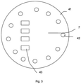
- FIG. 3 is a structural view of a light source plate of the LED lighting apparatus.
- FIG. 4 is a driver relation schematic diagram of the lighting apparatus.
- FIG. 5 is a schematic diagram of a driver circuit of the LED lighting apparatus.
- FIG. 6 is a structural frame diagram of a constant current driver chip of the LED lighting apparatus.
- FIG. 7 shows another embodiment with wireless functions.
- FIG. 8 shows another embodiment.
- a LED lighting apparatus 100 includes a housing 1 , a bulb shell 2 , a driver plate 3 , a light source plate 4 , and a driver circuit 5 .
- the bub shell 2 and the housing 1 are connected and form a container space 20 .
- the driver plate 3 , the light source plate 4 , and the driver circuit 5 are set in the container space 20 .
- the light source plate 4 includes a base plate 41 and a light emitting component 42 on the base plate 41 .
- the light emitting component 42 is set and illuminate in the direction of the bulb shell 2 .
- the driver circuit 5 is for driving the light emitting component 42 , converting the external power source into the direct current in needed voltage, and supplying the direct current to the light emitting component 42 .
- the driver circuit 5 includes at least a rectifier circuit 52 and a constant current driver chip 7 which are electrically connected, and the rectifier circuit 52 is set on the driver plate 3 .
- the constant current driver chip 7 is set on the light source plate 4 and coupled with the light emitting component 42 to supply constant current to the light emitting component 42 .
- the LED light apparatus 100 includes a housing 1 , a bulb shell 2 , a driver plate 3 , a light source plate 4 , and a driver circuit 5 .
- the housing 1 and the bulb shell 2 are connected.
- the driver plate 3 is in a container space 20 formed by the bulb 2 and the housing 1 .
- the light source plate 4 includes a base plate 41 and a light emitting component 42 on the base plate 41 .
- the driver circuit 5 includes a rectifier circuit 52 and a constant current driver chip 7 which are electrically connected.
- the rectifier circuit 52 is set on the driver plate 3 .
- the constant current driver chip 7 is set on the light source plate 4 and coupled with the light emitting component 42 .
- the constant current driver chip 7 is installed onto the light source plate 4 in the form of a patch.
- the integrity of the LED lighting apparatus may be higher. At the same time, the glue wrapping in conventional process may be avoided.
- the manufacturing efficiency may be higher, which is good for automated manufacturing.
- the material cost and the manufacturing cost may be reduced.
- the bulb shell 2 is for refraction of the light coming from the light emitting component 42 and for making the light more even and softer.
- the housing 1 may be made from aluminum coated plastic.
- the outer layer is plastic, and the inside is aluminum.
- the material may be for containing the driver plate 3 and enhancing the heat dissipation function of the housing 1 .
- the heat on the light source plate 4 and the driver plate 3 may be exported on time to make sure that the driver circuit 5 and the light emitting component 42 work normally.
- the LED lighting apparatus 100 also includes a light head 6 .
- the light head 6 includes a screw light head 61 and a conductive pin 62 .
- the conductive 62 is set in the center of the screw light head in the form of an electricity insulation.
- the screw light head 6 61 and the conductive pin 62 are connected to the two ends of the driver circuit 5 respectively and supply the external power source to the driver circuit 5 for converting and downscale voltage.
- the screw light head 61 has inner screw groove.
- the light head 6 is set around the bottom of the housing 1 .
- the driver plate 3 on the driver plate 3 is two power wires 8 .
- One of the power wires 8 is electrically connected between the input end and the live wire of the driver circuit 5 .
- the other power wire 8 is connected between the output end and the neutral wire of the driver circuit 5 , which forms a current circuit.
- the bottom of the housing 1 has a wiring hole 9 .
- the power wire connected between the input end and the live wire of the driver circuit 5 passes through the wiring hole 9 to be connected to the screw light head 61 .
- the wiring hole 9 may be a through hole or an open form on the edge of the bottom of the housing 1 based on the actual situation.
- the light source plate 4 is multiple light emitting components 42 .
- the multiple light emitting component 42 may be arranged into at least one circular shape so as to be spread out more evenly on the base plate 41 to ensure the uniformity of light emission in every direction of the LED lighting apparatus 100 .
- the light emitting component 42 is a LED component.
- the light color may be chosen based on the actual needs.
- the light color may be white, multicolored, or the combination of white and multicolor. There is no limitation.
- the driver plate 3 has multiple output terminals 31 .
- the output terminals 31 are electrically connected to the corresponding connecting terminals 43 to connect the rectifier circuit 52 on the driver plate 3 with the light emitting component 42 on the base plate 41 and the constant current driver chip 7 .
- the rectifier circuit 52 includes a rectifier bridge BD.
- the two input ends are respectively connected to a live wire L and a neutral wire.
- the output positive end is connected to the positive end of the light emitting component 42 .
- the driver circuit 5 includes an anti-surge circuit 51 , a voltage conversion circuit 53 , a vent circuit 54 , a vent isolation circuit 55 , a strobe filtering circuit 56 , and a chip power supply circuit 57 .
- the anti-verge circuit 51 is connected between the live wire L and the corresponding input end of the rectifier circuit 52 to suppress the voltage surge.
- the anti-surge circuit 51 includes a wire wood resistor FR.
- One end of the wire wood resistor FR is connected to the live wire L. The other end is connected to the corresponding input end of the rectifier bridge BD.
- the voltage conversion circuit 53 is for converting the voltage to transmit electrical energy.
- the voltage conversion circuit 53 includes a voltage transformer W.
- the two ends are respectively connected to the output positive end and the output negative end of the rectifier circuit 52 .
- vent circuit 54 One end of the vent circuit 54 is connected to the vent isolation circuit 55 .
- the other end is grounded to vent the excessive voltage of the input end to ensure safety.
- the vent isolation circuit 55 is connected between the output end of the voltage conversion circuit 53 and the positive end of the light emitting component 42 and between the output end of the voltage conversion circuit 53 and the vent circuit 54 .
- the vent isolation circuit 55 is for isolating the vented current from the light emitting component 42 .
- vent isolation circuit 55 includes at least one diode.
- the vent isolation circuit 55 includes a diode D 1 and a diode D 2 .
- the positive ends of the diodes D 1 and D 2 are connected to the output end of the voltage conversion circuit 53 .
- the negative end of the diode D 1 is connected to the positive end of the light emitting component 42 .
- the negative end of the diode D 2 is connected to the vent circuit 54 .
- the strobe filtering circuit 56 is connected in parallel with the light emitting component 42 .
- the strobe filtering circuit 56 is for filtering the alternating wave component from the direct current.
- the strobe filtering circuit 56 includes at least on electrolytic capacitor component 561 .
- the strobe filtering circuit 56 includes two electrolytic capacitors R 7 and R 7 A which are connected in parallel.
- One end of the electrolytic capacitor R 7 and one end of the electrolytic capacitor R 7 A are electrically connected to the positive end of the light emitting component 42 .
- the other end of the electrolytic capacitor R 7 and the other end of the electrolytic capacitor R 7 A are electrically connected to the negative end of the light emitting component 42 .
- the electrolytic capacitors R 7 and R 7 A may be set on the driver plate 3 .
- the chip power supply circuit 57 includes divider resistors R 1 and R 1 A.
- One end of the divider resistor R 1 and one end of the divider resistor R 1 A are connected to the positive end of the light emitting component 42 .
- the other end of the divider resistor R 1 and the other end of the divider resistor R 1 A get needed chip power supply voltages Vcc and Vcc 1 .
- the constant current driver chips 7 are connected in parallel for diversion to avoid every constant current driver chip 7 from being burned out because of excessive current.
- the two constant current driver chips are respectively U 1 and U 1 A and have the same structure.
- the chip power supply circuit 57 diverges into two ends.
- the two ends are constant current driver chip U 1 and U 1 A to supply power source.
- vent circuit 54 and the constant current driver circuit 5 are integrated on the constant current driver chip 7 by choosing the suitable model of constant current driver chip U 1 and U 1 A.
- the constant current driver chip U 1 includes a power pin VCC, a vent pin IBLE, a current input pin PVIN, a current output pin VS, a dimming pin CF 2 , and a ground pin GND. Also, the constant current driver chip U 1 may include a compensation pin COMP and at least one vacant space for another pin (indicated by NC in FIG. 5 ).
- the power pin VCC is connected to the chip power supply voltage Vcc of the chip power supply circuit 57 to drive the constant current driver chip to work.
- the vent pin IBLE passes through the resistance R 6 to be connected to the negative end of the diode D 2 to sense strength of the current passing through the diode D 2 .
- the current input pin PVIN is connected to the negative end of the light emitting component 42 .
- the current output pin VS is grounded.
- the dimming pin CF 2 is for connecting the dimmer.
- the ground pin GND is for grounding.
- a dimming module 71 a vent module 72 , and field effect transistor MOS 1 and MOS 2 are integrated in the constant current driver chip U 1 .
- the dimming module 71 is connected to the gate of the field effect transistor MOS.
- the current input pin PVIN is connected to the drain electrode of the field effect transistor MOS 1 .
- the current output pin VS is connected to the source electrode of the field effect transistor MOS 1 .
- the vent module 72 is connected to the gate of the field effect transistor MOS 2 .
- the vent pin IBLE is connected to the drain electrode of the field effect transistor MOS 2 .
- the source electrode of the field effect transistor MOS 2 is grounded.
- the output current of the current output pin VS is related to the gate source electrode voltage of the field effect transistor MOS 1 , and the current output from the current output pin VS may be guaranteed to be stable by making sure that the gate source electrode voltage is stable.
- the current output pin VS is connected to the dimming module 71 to give the feedback about the strength of the current to the dimming module 71 .
- the dimming module 71 runs comparison and adjustment based on the feedback about the strength of the current to further stabilize and adjust the output current of the current output pin VS.
- the field effect transistor MOS 1 may work in the MOSFET.
- the dimming pin CF 2 When the dimming pin CF 2 is connected to the dimmer (the dimmer is not grounded like in FIG. 5 ), by inputting the dimming signal, the dimming pin CF 2 changes the gate source electrode voltage of the field effect transistor MOS 1 to change the current of the current output pin VS to adjust the light.
- the dimming signal of the dimming pin CF 2 may be input into the vent module 72 at the same time.
- the constant current driver U 1 and the whole circuit may be guaranteed to work in the best condition by the field effect transistor MOS 2 and the vent pin IBLE compensating and absorbing the leakage current.
- the two ends of the light emitting component 42 are connected in parallel with the vent protection resistor R 6 .
- the vent protection resistor R 6 is for venting the electrical charge of the electrolytic capacitors R 7 and R 7 A to protect the light emitting component 42 when the circuit is off.
- the vent protection resistor R 6 is preferably set on the driver plate 3 , which may simplify the design of the light source plate 4 .
- FIG. 1 , FIG. 2 , and FIG. 5 in the embodiment, there are four connecting terminals 43 and four output terminals 31 .
- Each connecting terminal 43 corresponds to one output terminal 31 .
- One connecting terminal 43 and one output terminal 31 form an electrical terminal.
- the electrical terminal is for connecting a part of the driver circuit 5 on the driver plate 3 to a part of the driver circuit 5 on the light source plate 4 .
- one electrical terminal is connected to the positive end of the light emitting component 42 .
- Another electrical terminal is set between the divider resistor R 6 and R 6 A and the diode D 2 .
- the divider resistor R 6 and R 6 A may be set on the light source plate 4 .
- Another electrical terminal is connected between the output end of the chip power supply circuit 57 and the input end VCC of the driver chips U 1 and U 1 A.
- the last electrical terminal is for grounding the current output ends VS of the two driver chips U 1 and U 1 A, the ground end GND, and other pins that need to be grounded through the driver plate 3 .
- LED Light-Emitting Diode
- LED has the advantages of low working voltage and high optical efficiency.
- LED is considered to be a new light source of lighting in 21st century.
- a driver circuit of a LED light bulb is integrated on a driver module.
- the driver module In order to meet the heat dissipation need, during assembly, the driver module needs glue wrapping, and the glue wrapping leads to higher overall cost and complicated production.
- the LED lighting apparatus is for solving the technical problems that the conventional LED lighting apparatus has higher overall cost and complicated operation.
- a LED lighting apparatus includes a housing, a bulb shell, a driver plate, a light source plate, and a driver circuit.
- the bulb shell is connected to the housing.
- the bulb shell and the housing form a container space.
- the driver plate is set in the container space.
- the light source plate is set in the container space.
- the light source plate includes a base plate and a light emitting component on the base plate.
- the driver circuit includes a rectifier circuit and a constant current driver chip which are electrically connected to each other.
- the rectifier circuit is set on the driver plate.
- the constant current driver chip is set on the light source plate.
- the light emitting component is coupled with the constant current driver chip.
- on the driver plate includes multiple output terminals.
- On the light source plate includes multiple connecting terminals.
- the output terminals are connected to the corresponding connecting terminals one to one to electrically connect the light emitting component and the constant current driver chip to the rectifier circuit respectively.
- the LED lighting apparatus includes a light head connected to the bottom of the housing.
- the light head includes a screw light head with electricity insulation and a conductive pin set in the middle part of the screw light head.
- the screw light head and the conductive pin are electrically connected to the two input ends of the rectifier circuit respectively.
- the LED lighting apparatus includes two power wires.
- the bottom of the housing includes a wiring hole.
- One of the power wires passes through the wiring hole and is electrically connected to an input end of the rectifier circuit and the screw light head respectively.
- the other power wire is in the screw light head and is electrically connected to the other input end of the rectifier circuit and the conductive pin.
- the driver circuit includes a voltage conversion circuit.
- the voltage conversion circuit is connected between the output positive end of the rectifier circuit and the output negative end of the rectifier circuit.
- the voltage conversion circuit is set on the driver plate.
- the driver circuit includes a strobe filtering circuit.
- the strobe filtering circuit is connected in parallel to the light emitting component.
- the strobe filtering circuit includes at least one electrolytic capacitor.
- the strobe filtering circuit is set on the driver plate.
- the constant current driver chip includes a dimming module, a power pin, a current input pin, and a current output pin.
- the power pin is connected to a chip power supply circuit in the driver circuit.
- the current input pin is connected between a negative end of the light emitting component and the dimming module.
- the current output pin is grounded.
- the dimming module is for controlling the output current of the current output pin.
- the LED lighting apparatus includes a dimmer.
- the driver chip also includes a dimming pin.
- the dimming pin is connected between the dimmer and the dimming module. And the dimming pin is for inputting the dimming signal of the dimmer to the dimming module.
- the dimming module controls the output current of the current output pin based on the dimmer signal.
- the driver chip also includes a vent pin and a vent module.
- the vent module is connected to the dimming pin.
- the vent pin is connected to the vent module.
- the vent module is for venting current.
- the driver circuit also includes a vent protection resistor.
- Two ends of the vent protection resistor are respectively connected to the positive end and the negative end of the light emitting component.
- the vent protection resistor is set on the driver plate.
- the LED lighting apparatus includes a housing, a bulb shell, a driver plate, a light source plate, and a driver circuit.
- the bulb shell is connected to the housing.
- the driver plate is in the container space formed by the bulb shell and the housing.
- the light source plate includes a base plate and a light emitting component on the base plate.
- the driver circuit includes a rectifier circuit and a constant current driver chip which are electrically connected.
- the rectifier circuit is set on the driver plate.
- the constant current driver chip is set on the light source plate and is coupled with the light emitting component.
- the constant current driver chip is set on the light source plate in the form of a patch.
- the integrity of the LED lighting apparatus may be higher. At the same time, the glue wrapping in conventional process may be avoided.
- the manufacturing efficiency may be higher, which is good for automated manufacturing.
- the material cost and the manufacturing cost may also be reduced.
- the lighting apparatus may also include a wireless circuit 8801 for receiving program codes from an external device 8802 tt , a driver circuit 8803 on the driver plate 8804 executes the program codes for changing how to drive the light emitting component 8805 .
- the program codes define dividing the light emitting components 8805 into multiple groups 8806 , 8807 and controlling the multiple groups 8806 , 8807 separately for achieving a visual effect, mixing different color temperatures corresponding to the program codes.
- the lighting apparatus may also include a manual switch 8808 to disable the driver circuit to execute the program codes.
- the driver circuit detects authenticity of the program codes, if a hacking code is detected, the driver circuit is switched as a safe mode to keep a safe operation.
- the driver circuit detects authenticity by recognizing a biological identical information from a detector 8809 connected to the driver circuit 8803 .
- the lighting apparatus may also include an antenna 8809 being disposed with a metal shield 8810 between the antenna 8809 and the driver circuit 8803 .
- the driver plate 8701 and the light source plate 8702 are heat connected to two thermal isolated heat sinks 8703 , 8704 .
- the lighting apparatus may also include two separate temperature detectors 8705 , 8706 on the driver plate 8701 and the light source plate 8702 to change an operation mode for the driver plate and the light source plate.
Landscapes
- Engineering & Computer Science (AREA)
- Microelectronics & Electronic Packaging (AREA)
- General Engineering & Computer Science (AREA)
- Physics & Mathematics (AREA)
- Optics & Photonics (AREA)
- Computer Networks & Wireless Communication (AREA)
- Circuit Arrangement For Electric Light Sources In General (AREA)
- Non-Portable Lighting Devices Or Systems Thereof (AREA)
Abstract
Description
Claims (19)
Priority Applications (1)
| Application Number | Priority Date | Filing Date | Title |
|---|---|---|---|
| US16/852,469 US11234305B2 (en) | 2020-04-18 | 2020-04-18 | Lighting apparatus |
Applications Claiming Priority (1)
| Application Number | Priority Date | Filing Date | Title |
|---|---|---|---|
| US16/852,469 US11234305B2 (en) | 2020-04-18 | 2020-04-18 | Lighting apparatus |
Publications (2)
| Publication Number | Publication Date |
|---|---|
| US20210329762A1 US20210329762A1 (en) | 2021-10-21 |
| US11234305B2 true US11234305B2 (en) | 2022-01-25 |
Family
ID=78081021
Family Applications (1)
| Application Number | Title | Priority Date | Filing Date |
|---|---|---|---|
| US16/852,469 Active US11234305B2 (en) | 2020-04-18 | 2020-04-18 | Lighting apparatus |
Country Status (1)
| Country | Link |
|---|---|
| US (1) | US11234305B2 (en) |
Families Citing this family (2)
| Publication number | Priority date | Publication date | Assignee | Title |
|---|---|---|---|---|
| US11737185B2 (en) * | 2020-08-19 | 2023-08-22 | Jiangsu Caihuixin Electronic Technology Co., Ltd. | LED control system using modulated signal |
| CN217904698U (en) * | 2022-05-09 | 2022-11-25 | 漳州立达信光电子科技有限公司 | Light source assembly, light source driving circuit and lamp |
Citations (6)
| Publication number | Priority date | Publication date | Assignee | Title |
|---|---|---|---|---|
| US20160035201A1 (en) * | 2014-07-30 | 2016-02-04 | Tyco Fire & Security Gmbh | Notification appliance |
| US9534773B1 (en) * | 2014-09-04 | 2017-01-03 | Andy Turudic | 2-D lamp with integrated thermal management and near-ideal light pattern |
| US20170086281A1 (en) * | 2015-01-06 | 2017-03-23 | Cmoo Systems Ltd. | Method and Apparatus for Power Extraction in a Pre-Existing AC Wiring Infrastructure |
| US20190249831A1 (en) * | 2018-02-12 | 2019-08-15 | Xiamen Eco Lighting Co. Ltd. | Light bulb apparatus |
| US20190320515A1 (en) * | 2018-04-15 | 2019-10-17 | Laurence P. Sadwick | Solid State Lighting Systems |
| US20210080084A1 (en) * | 2018-05-14 | 2021-03-18 | Michael D. Danesh | Lighting module having integrated electrical connector |
-
2020
- 2020-04-18 US US16/852,469 patent/US11234305B2/en active Active
Patent Citations (7)
| Publication number | Priority date | Publication date | Assignee | Title |
|---|---|---|---|---|
| US20160035201A1 (en) * | 2014-07-30 | 2016-02-04 | Tyco Fire & Security Gmbh | Notification appliance |
| US9534773B1 (en) * | 2014-09-04 | 2017-01-03 | Andy Turudic | 2-D lamp with integrated thermal management and near-ideal light pattern |
| US20170086281A1 (en) * | 2015-01-06 | 2017-03-23 | Cmoo Systems Ltd. | Method and Apparatus for Power Extraction in a Pre-Existing AC Wiring Infrastructure |
| US9839103B2 (en) * | 2015-01-06 | 2017-12-05 | Cmoo Systems Ltd. | Method and apparatus for power extraction in a pre-existing AC wiring infrastructure |
| US20190249831A1 (en) * | 2018-02-12 | 2019-08-15 | Xiamen Eco Lighting Co. Ltd. | Light bulb apparatus |
| US20190320515A1 (en) * | 2018-04-15 | 2019-10-17 | Laurence P. Sadwick | Solid State Lighting Systems |
| US20210080084A1 (en) * | 2018-05-14 | 2021-03-18 | Michael D. Danesh | Lighting module having integrated electrical connector |
Also Published As
| Publication number | Publication date |
|---|---|
| US20210329762A1 (en) | 2021-10-21 |
Similar Documents
| Publication | Publication Date | Title |
|---|---|---|
| US11174996B2 (en) | Lighting apparatus | |
| JP5690930B2 (en) | Bleed circuit to prevent inappropriate dimming operation and related method | |
| US20240363673A1 (en) | Led package set and led bulb including same | |
| US11375592B2 (en) | Lighting apparatus | |
| US11175013B2 (en) | Ceiling light apparatus | |
| US11006496B2 (en) | LED lamp with current-regulated warm dimming | |
| US9759389B2 (en) | LED based candelabra lamp | |
| US11234305B2 (en) | Lighting apparatus | |
| US11212891B2 (en) | Light tube apparatus | |
| US11226072B2 (en) | Lighting apparatus having enhanced wireless single capability | |
| US11248783B2 (en) | Lighting apparatus | |
| EP3745014B1 (en) | Light bulb | |
| US11859773B2 (en) | Light bulb apparatus | |
| US11177095B2 (en) | Wall grazer apparatus | |
| US11378267B2 (en) | Wiring box for lighting apparatus | |
| US11419192B2 (en) | Lighting apparatus | |
| US11333306B2 (en) | Light bulb apparatus | |
| US11212897B2 (en) | Lighting apparatus | |
| US11184965B2 (en) | Light emitting diode driving circuit | |
| CN209672087U (en) | A kind of LED lamp |
Legal Events
| Date | Code | Title | Description |
|---|---|---|---|
| AS | Assignment |
Owner name: XIAMEN ECO LIGHTING CO. LTD., CHINA Free format text: ASSIGNMENT OF ASSIGNORS INTEREST;ASSIGNORS:LIU, JINYONG;CHEN, BIAO;LIN, HONGBIN;AND OTHERS;REEL/FRAME:052435/0695 Effective date: 20200416 |
|
| FEPP | Fee payment procedure |
Free format text: ENTITY STATUS SET TO UNDISCOUNTED (ORIGINAL EVENT CODE: BIG.); ENTITY STATUS OF PATENT OWNER: SMALL ENTITY |
|
| FEPP | Fee payment procedure |
Free format text: ENTITY STATUS SET TO SMALL (ORIGINAL EVENT CODE: SMAL); ENTITY STATUS OF PATENT OWNER: SMALL ENTITY |
|
| STPP | Information on status: patent application and granting procedure in general |
Free format text: NOTICE OF ALLOWANCE MAILED -- APPLICATION RECEIVED IN OFFICE OF PUBLICATIONS |
|
| STPP | Information on status: patent application and granting procedure in general |
Free format text: PUBLICATIONS -- ISSUE FEE PAYMENT RECEIVED |
|
| STPP | Information on status: patent application and granting procedure in general |
Free format text: PUBLICATIONS -- ISSUE FEE PAYMENT VERIFIED |
|
| STCF | Information on status: patent grant |
Free format text: PATENTED CASE |
|
| MAFP | Maintenance fee payment |
Free format text: PAYMENT OF MAINTENANCE FEE, 4TH YR, SMALL ENTITY (ORIGINAL EVENT CODE: M2551); ENTITY STATUS OF PATENT OWNER: SMALL ENTITY Year of fee payment: 4 |