US11234101B2 - Determining an orientation and body location of a wearable device - Google Patents
Determining an orientation and body location of a wearable device Download PDFInfo
- Publication number
- US11234101B2 US11234101B2 US15/713,051 US201715713051A US11234101B2 US 11234101 B2 US11234101 B2 US 11234101B2 US 201715713051 A US201715713051 A US 201715713051A US 11234101 B2 US11234101 B2 US 11234101B2
- Authority
- US
- United States
- Prior art keywords
- signal
- wearable device
- orientation
- subject
- location
- Prior art date
- Legal status (The legal status is an assumption and is not a legal conclusion. Google has not performed a legal analysis and makes no representation as to the accuracy of the status listed.)
- Active, expires
Links
Images


Classifications
-
- H—ELECTRICITY
- H04—ELECTRIC COMMUNICATION TECHNIQUE
- H04W—WIRELESS COMMUNICATION NETWORKS
- H04W4/00—Services specially adapted for wireless communication networks; Facilities therefor
- H04W4/02—Services making use of location information
- H04W4/025—Services making use of location information using location based information parameters
- H04W4/026—Services making use of location information using location based information parameters using orientation information, e.g. compass
-
- G—PHYSICS
- G08—SIGNALLING
- G08C—TRANSMISSION SYSTEMS FOR MEASURED VALUES, CONTROL OR SIMILAR SIGNALS
- G08C23/00—Non-electrical signal transmission systems, e.g. optical systems
- G08C23/04—Non-electrical signal transmission systems, e.g. optical systems using light waves, e.g. infrared
-
- H—ELECTRICITY
- H04—ELECTRIC COMMUNICATION TECHNIQUE
- H04B—TRANSMISSION
- H04B17/00—Monitoring; Testing
- H04B17/20—Monitoring; Testing of receivers
- H04B17/27—Monitoring; Testing of receivers for locating or positioning the transmitter
-
- H—ELECTRICITY
- H04—ELECTRIC COMMUNICATION TECHNIQUE
- H04B—TRANSMISSION
- H04B17/00—Monitoring; Testing
- H04B17/30—Monitoring; Testing of propagation channels
- H04B17/309—Measuring or estimating channel quality parameters
- H04B17/318—Received signal strength
-
- A—HUMAN NECESSITIES
- A61—MEDICAL OR VETERINARY SCIENCE; HYGIENE
- A61B—DIAGNOSIS; SURGERY; IDENTIFICATION
- A61B5/00—Measuring for diagnostic purposes; Identification of persons
- A61B5/02—Detecting, measuring or recording for evaluating the cardiovascular system, e.g. pulse, heart rate, blood pressure or blood flow
- A61B5/024—Measuring pulse rate or heart rate
- A61B5/02438—Measuring pulse rate or heart rate with portable devices, e.g. worn by the patient
-
- A—HUMAN NECESSITIES
- A61—MEDICAL OR VETERINARY SCIENCE; HYGIENE
- A61B—DIAGNOSIS; SURGERY; IDENTIFICATION
- A61B5/00—Measuring for diagnostic purposes; Identification of persons
- A61B5/45—For evaluating or diagnosing the musculoskeletal system or teeth
- A61B5/4504—Bones
-
- A—HUMAN NECESSITIES
- A61—MEDICAL OR VETERINARY SCIENCE; HYGIENE
- A61B—DIAGNOSIS; SURGERY; IDENTIFICATION
- A61B5/00—Measuring for diagnostic purposes; Identification of persons
- A61B5/68—Arrangements of detecting, measuring or recording means, e.g. sensors, in relation to patient
- A61B5/6801—Arrangements of detecting, measuring or recording means, e.g. sensors, in relation to patient specially adapted to be attached to or worn on the body surface
- A61B5/6802—Sensor mounted on worn items
- A61B5/681—Wristwatch-type devices
-
- A—HUMAN NECESSITIES
- A61—MEDICAL OR VETERINARY SCIENCE; HYGIENE
- A61B—DIAGNOSIS; SURGERY; IDENTIFICATION
- A61B5/00—Measuring for diagnostic purposes; Identification of persons
- A61B5/68—Arrangements of detecting, measuring or recording means, e.g. sensors, in relation to patient
- A61B5/6801—Arrangements of detecting, measuring or recording means, e.g. sensors, in relation to patient specially adapted to be attached to or worn on the body surface
- A61B5/6844—Monitoring or controlling distance between sensor and tissue
Definitions
- the present disclosure generally relates to wearable electronic devices and in particular to a method for configuring output devices of a wearable electronic device.
- FIG. 1 illustrates a wearable device within which certain aspects of the disclosure can be practiced, in accordance with one or more embodiments
- FIG. 2 illustrates an example wearable device that is configured to detect its current orientation and body location, in accordance with one or more embodiments of the disclosure
- FIG. 3A illustrates an example wearable device that is worn on a wrist of a subject in a left hand upright orientation in accordance with one or more embodiments
- FIG. 3B illustrates an example wearable device that is worn on a wrist of a subject in a left hand reverse orientation in accordance with one or more embodiments
- FIG. 3C illustrates an example wearable device that is worn on a wrist of a subject in a right hand upright orientation in accordance with one or more embodiments
- FIG. 3D illustrates an example wearable device that is worn on a wrist of a subject in a right hand reverse orientation in accordance with one or more embodiments
- FIG. 4 illustrates a wearable device having a first IR sensor and a second IR sensor and which is worn on a wrist of a subject, in accordance with one or more embodiments of the disclosure
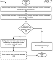
- FIG. 6 is a flow chart illustrating a method for using infrared light detection to configure a wearable device for a particular orientation and body location, in accordance with one or more embodiments.
- FIG. 7 is a flow chart illustrating a method for using bone conduction and infrared light detection to configure a wearable device for a particular orientation and body location, in accordance with one or more embodiments.
- the illustrative embodiments provide a method, a system, and a computer program product for configuring output devices of a wearable device based on a detected orientation and body location of the wearable device.
- the method includes measuring at least one orientation input via at least one orientation module of a wearable device.
- the method further includes analyzing, via a processor of the wearable device, the at least one orientation input to determine a body location of the wearable device and a current orientation of the wearable device at the body location.
- the method further includes configuring at least one output device of the wearable device for operation in the current orientation at the body location.
- references within the specification to “one embodiment,” “an embodiment,” “embodiments”, or “one or more embodiments” are intended to indicate that a particular feature, structure, or characteristic described in connection with the embodiment is included in at least one embodiment of the present disclosure.
- the appearance of such phrases in various places within the specification are not necessarily all referring to the same embodiment, nor are separate or alternative embodiments mutually exclusive of other embodiments.
- various features are described which may be exhibited by some embodiments and not by others.
- various aspects are described which may be aspects for some embodiments but not other embodiments.
- wearable device 100 may vary.
- the illustrative components within wearable device 100 are not intended to be exhaustive, but rather are representative to highlight components that can be utilized to implement the present disclosure.
- other devices/components may be used in addition to, or in place of, the hardware depicted.
- the depicted example is not meant to imply architectural or other limitations with respect to the presently described embodiments and/or the general disclosure.
- wearable device 100 within which one or more of the described features of the various embodiments of the disclosure can be implemented.
- wearable device 100 can be any electronic device that may be attached to a body of a subject/user.
- Example wearable devices can include, but are not limited to, wrist/smart watches, headphones, body cameras, and fitness trackers.
- Wearable device 100 includes at least one processor or central processing unit (CPU) 104 .
- CPU 104 is coupled to non-volatile storage 120 and system memory 110 , within which firmware 112 , operating system (OS) 116 , body orientation utility (BOU) 117 , and applications 118 can be stored for execution by CPU 104 .
- OS operating system
- BOU body orientation utility
- wearable device 100 may include input devices, such as hardware buttons 106 a - n , and output devices, such as display 145 , that enable a user to interface with wearable device 100 .
- Hardware buttons 106 a - n are selectable buttons that are used to receive manual/tactile input from a user to control specific operations of wearable device 100 and/or of applications executing thereon.
- hardware buttons 106 a - n may also include, or may be connected to, one or more sensors (e.g. a fingerprint scanner) and/or may be pressure sensitive.
- Hardware buttons 106 a - n may also be directly associated with one or more functions of a graphical user interface (not pictured) and/or functions of an OS, application, or hardware of wearable device 100 .
- hardware buttons 106 a - n may include a keyboard.
- Speakers 144 are used to output audio signals.
- speakers 144 include at least one transducer capable of outputting signals. The signals may include, but are not limited to, radio frequency (RF) signals, audio signals in the human audible range, and/or ultrasound signals.
- Wearable device 100 also includes microphone 108 .
- microphone 108 includes at least one audio receiver for capturing audio signals emitted by speakers 144 .
- microphone 108 may be used to receive spoken input/commands from a user.
- wearable device 100 can also include cameras (not illustrated) for capturing images and/or video.
- Display 145 is capable of displaying text, media content—including images and video, and/or a graphical user interface (GUI) associated with or generated by firmware and/or software executing on wearable device 100 .
- the GUI can be rendered by CPU 104 for viewing on display 145 , in at least one embodiment, or can be rendered by a graphics processing unit (GPU) (not separately shown), in another embodiment.
- display 145 is a touch screen that is capable of receiving touch/tactile input from wearable device 100 .
- wearable device 100 can include a plurality of virtual buttons or affordances that operate in addition to, or in lieu of, hardware buttons 106 a - n .
- wearable device 100 can be equipped with a touch screen interface and provide, via a GUI, a virtual keyboard or other virtual icons for user interfacing therewith.
- CPU 104 is also coupled to sensors 122 a - n .
- Sensors 122 a - n can include, but are not limited to, at least one of: infrared (IR) emitters, IR receivers, time-of-flight emitters/receivers, structured light emitters/receivers, thermal sensors, light sensors, motion sensors, and/or accelerometers, heart rate sensors, proximity sensors, and camera/image sensors.
- IR infrared
- Wearable device 100 also includes data port 132 (e.g., a universal serial bus (USB) port), battery 134 , and charging circuitry 136 .
- Data port 132 can operate as a charging port that receives power via an external charging device (not pictured) for charging battery 134 via charging circuitry 136 .
- Data port 132 may also function as one of an input port, an output port, and a combination input/output port for exchanging data via a serial or parallel connection with another device.
- Battery 134 may include a single battery or multiple batteries for providing power to components of wearable device 100 .
- battery 134 may include at least one battery that is removable and/or replaceable by an end user.
- battery 134 may include at least one battery that is permanently secured within/to wearable device 100 .
- Wearable device 100 may also include one or more wireless radios 140 a - n and can include one or more antenna(s) 148 a - n that enable wearable device 100 to wirelessly connect to, and transmit and receive voice and/or data communication to/from, one or more other devices, such as devices 152 a - n and server 154 .
- wearable device 100 can transmit data over a wireless network 150 (e.g., a Wi-Fi network, cellular network, Bluetooth® network (including Bluetooth® low energy (BLE) networks), a wireless ad hoc network (WANET), or personal area network(PAN)).
- a wireless network 150 e.g., a Wi-Fi network, cellular network, Bluetooth® network (including Bluetooth® low energy (BLE) networks), a wireless ad hoc network (WANET), or personal area network(PAN)
- wearable device 100 may be further equipped with an infrared (IR) device (not pictured) for communicating with other devices using an IR connection.
- wireless radios 140 a - n may include a short-range wireless device, including, but not limited to, a near field communication (NFC) device.
- wearable device 100 may communicate with one or more other device(s) using a wired or wireless USB connection.
- FIG. 2 is a block diagram illustrating additional functional components within example wearable device 100 , in accordance with one or more embodiments of the present disclosure.
- Wearable device 100 is configured to detected a current orientation and current body location and to configure input and/or output devices of the wearable device for operation at the detected current orientation and current body location.
- Wearable device 100 is an electronic device that is worn on the body of a subject (e.g., a person). In the illustrated embodiment, wearable device 100 is worn on body 202 at a wrist (or lower arm area) of a subject. In another embodiment, wearable device 100 may be worn at another body location of a subject, such as an arm, hand, leg, or chest, without limitation.
- wearable device 100 includes CPU 104 , memory 110 , and display 145 .
- CPU 104 executes BOU 117 to perform the various functional features of the disclosure described herein.
- CPU 104 receives orientation input 214 via at least one orientation module, such as transducers 204 a - n and/or IR proximity modules 210 a - n , and CPU 104 analyzes orientation input 214 to determine current orientation 220 and current location 222 of wearable device 100 on the body 202 (skin) of a subject.
- orientation module such as transducers 204 a - n and/or IR proximity modules 210 a - n
- CPU 104 compares orientation input 214 to at least one orientation profile, such as signal conduction profiles 224 a - n and/or IR profiles 226 a - n , to determine current orientation 220 (e.g., upright orientation or reverse orientation) and current location 222 (e.g, left hand or right hand) of wearable device 100 on body 202 of a subject.
- orientation profile includes and/or describes at least one signature of at least one return signal that is associated with at least one orientation module and further associates the signature(s) with a particular body location and/or orientation of wearable device 100 .
- FIGS. 3A-D there is illustrated four orientations in which wearable device 100 may be worn.
- FIG. 3A illustrates wearable device 100 worn in the left hand upright orientation.
- FIG. 3B illustrates wearable device 100 worn in the left hand reverse (i.e., downwards) orientation.
- FIG. 3C illustrates wearable device 100 worn in the right hand upright orientation.
- FIG. 3D illustrates wearable device 100 worn in the right hand reverse (downward) orientation.
- orientation profiles are retrieved in response to receiving a request from a user of wearable device 100 to retrieve and/or update orientation profiles stored in memory 110 .
- orientation profiles may be periodically synced between remote database 230 and wearable device 100 .
- remote database 230 may be a server (e.g., server 154 ) that is accessible to wearable device 100 and/or other wearable devices (not illustrated) via a network.
- remote database 230 may be hosted within at least one virtual server, such as a cloud service.
- the at least one orientation module of wearable device 100 includes at least one transducer 204 a - n and receiver 208 for determining a current orientation 220 and current location 222 of wearable device 100 on body 202 via bone conduction detection.
- the at least one orientation module of wearable device 100 includes a plurality of IR proximity modules 210 a - n for determining a current orientation 220 and current location 222 of wearable device 100 on body 202 via infrared light detection.
- the at least one orientation module of wearable device 100 includes (i) both transducers 204 a - n , and receiver 208 and (ii) IR proximity modules 210 a - n .
- CPU 104 may determine current orientation 220 and current location 222 of wearable device 100 on body 202 using one or both of bone conduction detection methods and infrared light detection methods, as described in greater detail below.
- wearable device 100 includes at least one transducer 204 a - n and at least one receiver 208 and utilizes these two components to determine a current orientation 220 and current location 222 of wearable device 100 on body 202 via bone conduction detection.
- transducer 204 a is located at a top side of wearable device 100
- receiver 208 is located in a center of wearable device 100
- transducer 204 n is located at a bottom side of wearable device.
- receiver 208 and transducers 204 a - n are physically located on an underside of wearable device 100 .
- receiver 208 and transducers 204 a - n are in physical contact with body 202 of the subject.
- receiver 208 and transducers 204 a - n may be touching the epidermis of the subject at the wrist.
- Transducers 204 a - n are used to transmit signals 206 a - n into body 202 .
- Signals 206 a - n may include, but are not limited to: radio frequency (RF) signals, vibrations, audio signals, which may or may not be in the human audible range (e.g., low frequency audio), and/or ultrasound signals.
- RF radio frequency
- each transmission (e.g., signal 206 a ) transmitted by a transducer includes more than one signal, with each signal being transmitted at a different frequency and/or output strength (amplitude).
- signal 206 a may include a first sine waveform that is transmitted by transducer 204 a at a frequency of 10 hertz (Hz) and a second sine waveform that is transmitted by transducer 204 a at 2 megahertz (MHz).
- signals 206 a - n can include at least one pulse signal.
- transmissions(s) e.g., signal 206 a
- first transducer e.g., transducer 204 a
- second transducer e.g., transducer 204 n
- Signals 206 a - n can be transmitted by transceivers 204 a - n during a same time period or a different time period.
- CPU 104 may transmit signal 206 a by transducer 204 a during a first 2-second time period and may transmit signal 206 n (which is a same or different signal as signal 206 a ) by transducer 204 n during a second 2-second time period that is different from the first 2-second time period.
- CPU 104 may transmit signal 206 a by transducer 204 a and transmit signal 206 n (which is different than signal 206 a ) by transducer 204 n during the same 2-second time period.
- receiver 208 measures orientation input 214 , which includes signals 206 a - n ′.
- Signals 206 a - n ′ are signals 206 a - n transmitted by transducers 204 a - n into body 202 through an epidermis and at least one bone of the subject.
- signals 206 a - n ′ may pass through artificial materials such as articles of clothing and/or prosthetic body parts.
- CPU 104 determines characteristics 218 a - n of signals 206 a - n ′ in orientation input 214 .
- Measured characteristics 218 a - n may include, but are not limited to, a frequency, phase shift, amplitude, quality, noise, and/or distortion within signals 206 a - n ′.
- CPU 104 may compute a phase shift of signal 206 a ′ and an amplitude of signal 206 a ′ at a plurality of frequencies.
- the type, size, density, and composition of bone and the skin layer will affect characteristics of signals 206 a - n as they pass through the body from a transducer to a receiver.
- CPU 104 analyzes the measured characteristics 218 a - n to determine whether the at least one of signals 206 a - n ′ include characteristics that correspond to a passage of the at least one of signals 206 a - n through at least one bone of a subject. If the analysis does not conclusively determine that at least one of signals 206 a - n has passed through at least one bone of the subject, CPU 104 may re-transmit signals 206 a - n into body 202 by transducers 204 a - n and re-measure orientation input 214 via receiver 208 .
- CPU 104 may present an error message on display 145 that indicates that current orientation 220 and current location 222 of wearable device 100 was unable to be determined.
- the error message may also include a notification or message that requests a user of wearable device 100 manually select the current orientation 220 and current location 222 .
- each of signal conduction profiles 224 a - n includes a signature of at least one signal and associates the signature with a particular body location and orientation of wearable device 100 .
- signal conduction profiles 224 a may establish a first signature that contains characteristics of the passage of signal 206 a from transducer 204 a to receiver 208 through the ulna bone of an arm and a second signature that contains characteristics of the passage of signal 206 n from transducer 204 n to receiver 208 through the radius bone of an arm.
- signal conduction profiles 224 b may establish a first signature that contains characteristics of the passage of signal 206 a from transducer 204 a to receiver 208 through the tibia bone of a leg and a second signature that contains characteristics of the passage of signal 206 n from transducer 204 n to receiver 208 through the fibula bone of a leg.
- signal conduction profiles 224 a - n describe expected differences, such an expected phase shift, between a transmitted signal (signal 206 a ) and a corresponding measured signal (signal 206 a ′) for a particular orientation and/or body location of wearable device 100 .
- each signal conduction profile 224 a - n may contain multiple signatures for each signal.
- signal conduction profile 224 a may contain three different signatures that each describe different characteristics of the passage of signal 206 a from transducer 204 a to receiver 208 through the ulna bone of an arm.
- CPU 104 compares characteristics 218 a - n to signal characteristics of each signal conduction profile 224 a - n to determine a signal conduction profile that contains characteristics that mostly closely match characteristics 218 a - n . In response to determining a closest match from among signal conduction profiles 224 a - n , based on characteristics 218 a - n , CPU 104 determines current orientation 220 and current location 222 of wearable device 100 on body 202 .
- CPU 104 compares characteristics 218 a of signal 206 a to signal conduction profiles 224 a - n and determines that signal 206 a corresponds to a signal transmission through an ulna bone of an arm.
- CPU 104 compares characteristics 218 n of signal 206 n to signal conduction profiles 224 a - n and determines that signal 206 n corresponds to a signal transmission through a radius bone of an arm. Based on the comparisons of characteristics 218 a - n to signal conduction profiles 224 a - n , CPU 104 determines that wearable device 100 is located on a wrist of the subject.
- CPU 104 determines that wearable device 100 is in an upright orientation.
- wearable device 100 includes a plurality of IR proximity modules 210 a - n for determining a current orientation 220 and current location 222 of wearable device 100 on body 202 via infrared light detection.
- IR proximity modules 210 a - n include at least one emitter that projects IR signals 212 a - n within a predetermined range/angle onto a surface of body 202 and at least one receiver that receives IR return signals 216 a - n , which are reflections of IR signals 212 a - n off body 202 of the subject.
- CPU 104 in response to receiving IR return signals 216 a - n , computes a time of flight (ToF) associated with IR signals 212 a - n and IR return signals 216 a - n . In one or more embodiments, CPU 104 further analyzes the ToF data to determine current orientation 220 and current location 222 of wearable device 100 on body 202 .
- ToF time of flight
- wearable device 100 having a first IR sensor (IR sensor 402 a ) and a second IR sensor (IR sensor 402 n ).
- Wearable device 100 is worn on a wrist of a subject.
- the first IR sensor is attached to a first side of wearable device 100 and aligned in a first direction.
- the second IR sensor is attached to a second side of wearable device 100 and aligned in a second direction that is opposite the first direction.
- IR sensor 402 a projects IR light up the arm of the subject while IR sensor 402 n projects IR light in the opposite direction, towards the hand of the subject.
- IR sensor 402 a - n receive IR return signals that are reflections of the projected projects IR light.
- CPU 104 projects IR signals 212 a - n via IR proximity modules 210 a - n .
- IR proximity modules 210 a - n receive orientation input 214 , which includes IR return signals 216 a - n that are reflections of IR signals 212 a - n off body 202 of the subject.
- IR proximity module 210 a projects IR signals 212 a and also receives IR return signals 216 a .
- CPU 104 analyzes ToF data associated with IR return signals 216 a - n to determine at least one estimated distance measurement to body 200 of the subject.
- return signal 216 n may be analyzed to determine ToF measurements. The ToF measurements may then be used to estimate distances to at least one knuckle on the hand of the subject.
- IR profiles 226 a - n In response to receiving orientation input 214 (which includes IR return signals 216 a - n ), CPU 104 accesses IR profiles 226 a - n .
- each of IR profiles 226 a - n describes a profile of return signals associated with IR proximity modules 210 a - n and a particular body location and orientation of wearable device 100 .
- IR profiles 226 a - n may contain estimated distances and/or distance ranges to a particular body part, such as knuckles on a hand of a subject. In other embodiments, IR profiles may contain estimated distances to other body parts, such as measurements to elbows, ankles, ears, feet, and/or knees.
- IR profile 226 a - n include a range of measurements that account for anatomic variations between a variety of subjects.
- IR profiles 226 a - n may contain multiple signal profiles and/or at least one average return signal profile for particular IR signals projected by IR proximity modules 210 a - n .
- IR profile 226 a may be associated with a left hand upright wrist position of wearable device 100 and includes (1) a first profile that describes return distances and/or expected ToF data for IR signal 212 a projected by IR proximity modules 210 a up the arm of a subject and (2) a second profile that describes return distances and/or expected ToF data for IR signal 212 n projected by IR proximity modules 210 n towards the hand of the subject, such as measurements to one or more knuckles of a hand.
- IR profile 226 b may be associated with a right hand upright wrist position of wearable device 100 and includes (1) a first profile that describes return distances and/or expected ToF data for IR signal 212 n projected by IR proximity modules 210 n up the arm of a subject and (2) a second profile that describes return distances and/or expected ToF data for IR signal 212 a projected by IR proximity modules 210 a towards the hand of the subject.
- IR profile 226 n may be associated with first orientation of wearable device 100 on an ankle of a subject and includes (1) a first profile that describes return distances and/or expected ToF data for IR signal 212 a projected by IR proximity modules 210 a up the leg of a subject and (2) a second profile that describes return distances and/or expected ToF data for IR signal 212 n projected by IR proximity modules 210 n towards the foot of the subject.
- CPU 104 compares the ToF data and/or estimated distance measurements associated with IR return signals 216 a - n of IR profiles 226 a - n to determine an IR profile that mostly closely matches ToF data and/or distance measurements of IR return signals 216 a - n . In response to determining a closest match from among IR profiles 226 a - n , CPU 104 determines current orientation 220 and current location 222 of wearable device 100 on body 202 based on the closest matching IR profile.
- CPU 104 may determine, based on the ToF data and/or estimated distances associated with IR return signal 216 a , that IR proximity module 210 a is projecting IR signal 212 a towards a longer side of a body location, such as an arm. CPU 104 may then determine based on the ToF data and/or estimated distances calculated from IR return signals 216 a - n , that wearable device 100 is either being worn in a left hand upright orientation on a left wrist of a subject or a right hand reverse orientation on a right wrist of the subject.
- CPU 104 may then compare the estimated measurements (and/or ToF data associated with the reflected IR signals) associated with IR return signal 216 n to measurements contained in IR profiles 226 a - n .
- IR profile 226 a may include measurements and/or measurement ranges to knuckles of a subject when wearable device 100 is worn in a particular orientation (e.g., reverse orientation) and/or at a particular body part (e.g., right hand) of a subject.
- the estimated measurements associated with IR return signal 216 n may be compared to the estimated distances and/or distance ranges within IR profiles 226 a - n .
- CPU 104 may determine that (1) a closest estimated measurement in the range of IR return signals 216 n corresponds to a measurement within IR profile 226 a that is associated with a measurement to a knuckle of an index finger and (2) a farthest estimated measurement in the range of IR return signals 216 n corresponds to a measurement within IR profile 226 a that is associated with a measurement to a knuckle of a little (pinky) finger.
- CPU 104 can determine that wearable device 100 is currently being worn in a right hand reverse orientation on a right wrist of the subject.
- CPU 104 would determine that wearable device 100 is currently being worn in a left hand upright orientation on a left wrist of a subject.
- CPU 104 In response to determining current orientation 220 and current location 222 of wearable device 100 on body 202 , CPU 104 configures at least one output device of wearable device 100 for operation at the determined current orientation 220 and current location 222 . For example, in a right hand upright orientation, display 145 is configured to display a user interface in a first orientation. In response to determining that wearable device 100 is being worn in a right hand reverse orientation, CPU 104 may rotate the user interface 180 degrees such that user interface can be properly viewed by a user wearing wearable device 100 in the right hand reverse orientation.
- CPU 104 may also configure one or more input devices of wearable device 100 for operation at current orientation 220 and current location 222 .
- input button 106 a is associated with a volume up function and input button 106 n is associated with a volume down function.
- CPU 104 may reconfigure input buttons 106 a - n such that input button 106 a is associated with a volume down function and input button 106 n is associated with a volume up function.
- CPU 104 can reconfigure one or more sensors, such as a heart rate sensor for operation at current orientation 220 and current location 222 .
- CPU 104 may determine current orientation 220 and current location 222 using a combination of bone conduction detection methods and infrared light detection methods. In one embodiment, CPU 104 separately determines an estimated current orientation and current location of wearable device via the bone conduction detection methods and infrared light detection methods described above. In this embodiment, CPU 104 determines whether the estimated current orientation and current location determined by bone conduction detection matches the estimated current orientation and current location determined by infrared light detection.
- CPU 104 reconfigures at least one input device and/or at least one output device of wearable device 100 based on the determined current orientation 220 and current location 222 .
- one of the two detection methods is associated with a higher priority.
- CPU 104 may identify an estimated current orientation and current location associated with the higher priority detection method (e.g., bone conduction detection) as current orientation 220 and current location 222 of wearable device 100 .
- CPU 104 may present, an error message on display 145 that indicates that current orientation 220 and current location 222 of wearable device 100 was unable to be determined.
- CPU 104 may also present a message and/or notification that requests a user of wearable device 100 to manually select the current orientation 220 and current location 222 .
- the analysis of characteristics 218 a - n and/or IR return signals 216 a - n can be used to generate new signal conduction profiles 224 a - n and/or IR profiles 226 a - n or improve existing signal conduction profiles 224 a - n and/or IR profiles 226 a - n .
- CPU 104 may store characteristics 218 a - n and/or measurements associated with IR return signals 216 a - n in a corresponding profile within remote database 230 or a local storage (e.g., memory 110 ).
- CPU 104 may store characteristics 218 a - n and/or measurements associated with IR return signals 216 a - n within a new profile in remote database 230 .
- remote database 230 is accessible by other wearable devices (not illustrated) and each wearable device may access signal conduction profiles 224 a - n and/or IR profiles 226 a - n from remote database 230 . Additionally, each wearable device may store locally analyzed characteristics 218 a - n and measurements associated with IR return signals 216 a - n .
- Locally analyzed characteristics 218 a - n may be associated with existing profiles (signal conduction profiles 224 a - n and/or IR profiles 226 a - n ) in local storage (e.g., memory 110 ). Each wearable device may also forward characteristics 218 a - n and/or measurements associated with IR return signals 216 a - n to remote database 230 . Forwarded characteristics may be stored within new profiles created in remote database 230 and/or may be associated with existing profiles. Thus, any wearable device that can access remote database 230 may utilize analysis data collected by other remote databases to improve future detection of current orientation 220 and current location 222 .
- FIG. 5 there is depicted a high-level flow-chart illustrating a method for using bone conduction to configure a wearable device for a particular orientation and body location, in accordance with one or more embodiments of the present disclosure. Aspects of the method are described with reference to the components of FIGS. 1 and 2 .
- a processor e.g., CPU 104
- software code of BOU 117 within a wearable device (e.g., wearable device 100 ).
- the method processes described in FIG. 5 are generally described as being performed by components of wearable device 100 .
- Method 500 commences at initiator block 501 then proceeds to block 502 .
- wearable device 100 transmits a primary signal (signal 206 a ) by a first transducer (transducer 204 a ) into body 200 of a subject.
- CPU 104 measures, via receiver 208 , a return signal (signal 206 a ′). For example, CPU 104 may measure a phase shift between signal 206 a and signal 206 a ′ and/or an amplitude of signal 206 a ′ at a single frequency or a plurality of frequencies.
- wearable device 100 transmits a secondary signal (signal 206 n ) by a second transducer (transducer 204 a ) into body 200 of a subject.
- CPU 104 measures, via receiver 208 , a second return signal (signal 206 n ′). For example, CPU 104 may measure a phase shift between signal 206 n and signal 206 n ′ and/or an amplitude of signal 206 a ′ at a single frequency or a plurality of frequencies.
- CPU 104 analyzes the first and second return signals to identify characteristics 218 a - n (e.g., amplitude and/or signal quality) within those return signals.
- CPU 104 determines, based on characteristics 218 a - n , whether at least one signal has passed through the body and at least one bone of the subject. In response to determining neither of the first and second return signals passed through the body and at least one bone of the subject, CPU 104 presents an error message on an output device (e.g., display 145 ) that indicates that current orientation 220 and current location 222 of wearable device 100 was unable to be determined. CPU 104 may also present a message and/or notification that requests a user of wearable device 100 to manually select the current orientation 220 and current location 222 (block 526 ).
- an output device e.g., display 145
- CPU 104 may also present a message and/or notification that requests a user of wearable device 100 to manually select the current orientation 220 and current location 222 (block 526 ).
- CPU 104 retrieves signal conduction profiles 224 a - n (block 514 ).
- Signal conduction profiles 224 a - n may be retrieved from local storage (e.g., memory 110 ) or a remote database (e.g., remote database 230 ).
- CPU 104 compares characteristics (characteristics 218 a - n ) of the measured signals 206 a - n ′ to signal characteristics in signal conduction profiles 224 a - n .
- CPU 104 determines, based on results of the comparison, a current orientation (current orientation 220 ) of wearable device 100 of body 202 of the subject.
- CPU 104 determines, based on results of the comparison, a current body location (current location 222 ) of wearable device 100 of body 202 of the subject.
- CPU 104 configures at least one input device and/or output device of wearable device 100 for operation at the determined current orientation and current body location.
- CPU 104 may optionally store analysis data associated with the characteristics (characteristics 218 a - n ) of the measured signals 206 a - n ′ in a database (e.g., remote database 230 ). Method 500 then terminates at block 526 .
- FIG. 6 there is depicted a high-level flow-chart illustrating a method for using infrared light detection to configure a wearable device for a particular orientation and body location, in accordance with one or more embodiments of the present disclosure. Aspects of the method are described with reference to the components of FIGS. 1 and 2 .
- a processor e.g., CPU 104
- software code of BOU 117 within a wearable device (e.g., wearable device 100 ).
- the method processes described in FIG. 6 are generally described as being performed by components of wearable device 100 .
- Method 600 commences at initiator block 601 then proceeds to block 602 .
- wearable device 100 projects a first IR signal (IR signal 212 a ) by a first IR proximity module (IR proximity module 210 a ) in a first direction onto body 202 of a subject.
- CPU 104 receives, via the first IR proximity module, a first IR return signal (IR return signal 216 a ), which is a reflection of the projected first IR signal.
- wearable device 100 projects a second IR signal (IR signal 212 n ) by a second IR proximity module (IR proximity module 210 n ) in a second direction, that is opposite the first direction.
- CPU 104 receives, via the second IR proximity module, a second IR return signal (IR return signal 216 n ), which is a reflection of the projected second IR signal.
- CPU 104 retrieves IR profiles 226 a - n .
- IR profiles 226 a - n may be retrieved from local storage (e.g., memory 110 ) or a remote database (e.g., remote database 230 ).
- CPU 104 compares ToF data of IR return signals 212 a - n and/or estimated measurements associated with IR return signals 212 a - n to measurements within IR profiles 226 a - n .
- CPU 104 determines a particular IR profile from among IR profiles 226 a - n that includes measurements/measurement ranges and/or ToF data that most closely matches the ToF data and/or estimated measurements associated with IR return signals 212 a - n .
- CPU 104 identifies a current orientation (current orientation 220 ) and a current body location (current location 222 ) of wearable device 100 on the body of the subject (block 616 ).
- CPU 104 configures at least one input device and/or output device of wearable device 100 for operation at the determined current orientation and current body location.
- CPU 104 may optionally store data associated with the measurements in the IR return signals in a database (e.g., remote database 230 ). Method 600 then terminates at block 622 .
- FIG. 7 depicts a high-level flow-chart illustrating a method for using bone conduction and infrared light detection to configure a wearable device for a particular orientation and body location, in accordance with one or more embodiments of the present disclosure. Aspects of the method are described with reference to the components of FIGS. 1 and 2 .
- Several of the processes of the method provided in FIG. 7 can be implemented by a processor (e.g., CPU 104 ) executing software code of BOU 117 within a wearable device (e.g., wearable device 100 ).
- the method processes described in FIG. 7 are generally described as being performed by components of wearable device 100 .
- Method 700 commences at initiator block 701 then proceeds to block 702 .
- CPU 104 determines a first estimated current location and a first estimated current orientation via a bone conduction detection method (such as the bone conduction detection method described in steps 501 - 518 of FIG. 5 ).
- CPU 104 determines a second estimated current location and a second estimated current orientation via a IR light detection method (such as the IR light detection method described in steps 601 - 616 of FIG. 6 ).
- CPU 104 determines whether the two results (body location and current orientation of wearable device 100 ) match. That is, CPU 104 determines if the first estimated current location and the first estimated current orientation are the same as the second estimated current location and a second estimated current orientation, respectively.
- CPU 104 In response to determining a same body location and same current orientation of wearable device 100 via both the bone conduction detection method and the IR light detection method, CPU 104 configures at least one input device and/or output device of wearable device 100 for operation at the determined current orientation and current body location (block 708 ). At block 710 , CPU 104 may optionally store analysis data associated with the characteristics (characteristics 218 a - n ) of the measured signals 206 a - n ′ and data associated with the measurements in the IR return signals in a database (e.g., remote database 230 ). Method 700 then terminates at block 714 .
- a database e.g., remote database 230
- CPU 104 In response to determining that the bone conduction detection and the IR light detection method did not determine a same body location and/or a same current orientation of wearable device 100 , CPU 104 provides an error message on an output device (e.g., display 145 ) that indicates that the current orientation and the current location of wearable device 100 was unable to be determined (block 712 ). In one embodiment, CPU 104 also presents a notification or message that requests a user of wearable device 100 manually select the current orientation 220 and current location 222 (block 714 ). Method 700 then terminates at block 716 .
- an output device e.g., display 145
- CPU 104 also presents a notification or message that requests a user of wearable device 100 manually select the current orientation 220 and current location 222 (block 714 ).
- one or more of the method processes may be embodied in a computer readable device containing computer readable code such that a series of steps are performed when the computer readable code is executed on a computing device.
- certain steps of the methods are combined, performed simultaneously or in a different order, or perhaps omitted, without deviating from the scope of the disclosure.
- the method steps are described and illustrated in a particular sequence, use of a specific sequence of steps is not meant to imply any limitations on the disclosure. Changes may be made with regards to the sequence of steps without departing from the spirit or scope of the present disclosure. Use of a particular sequence is therefore, not to be taken in a limiting sense, and the scope of the present disclosure is defined only by the appended claims.
- aspects of the present disclosure may be implemented using any combination of software, firmware, or hardware. Accordingly, aspects of the present disclosure may take the form of an entirely hardware embodiment or an embodiment combining software (including firmware, resident software, micro-code, etc.) and hardware aspects that may all generally be referred to herein as a “circuit,” “module,” or “system.” Furthermore, aspects of the present disclosure may take the form of a computer program product embodied in one or more computer readable storage device(s) having computer readable program code embodied thereon. Any combination of one or more computer readable storage device(s) may be utilized.
- the computer readable storage device may be, for example, but not limited to, an electronic, magnetic, optical, electromagnetic, infrared, or semiconductor system, apparatus, or device, or any suitable combination of the foregoing. More specific examples (a non-exhaustive list) of the computer readable storage device can include the following: a portable computer diskette, a hard disk, a random access memory (RAM), a read-only memory (ROM), an erasable programmable read-only memory (EPROM or Flash memory), a portable compact disc read-only memory (CD-ROM), an optical storage device, a magnetic storage device, or any suitable combination of the foregoing.
- a computer readable storage device may be any tangible medium that can contain, or store a program for use by or in connection with an instruction execution system, apparatus, or device.
- tangible and non-transitory are intended to describe a computer-readable storage medium (or “memory”) excluding propagating electromagnetic signals; but are not intended to otherwise limit the type of physical computer-readable storage device that is encompassed by the phrase “computer-readable medium” or memory.
- non-transitory computer readable medium or “tangible memory” are intended to encompass types of storage devices that do not necessarily store information permanently, including, for example, RAM.
- Program instructions and data stored on a tangible computer-accessible storage medium in non-transitory form may afterwards be transmitted by transmission media or signals such as electrical, electromagnetic, or digital signals, which may be conveyed via a communication medium such as a network and/or a wireless link.
Landscapes
- Engineering & Computer Science (AREA)
- Physics & Mathematics (AREA)
- Computer Networks & Wireless Communication (AREA)
- Signal Processing (AREA)
- Electromagnetism (AREA)
- General Physics & Mathematics (AREA)
- Health & Medical Sciences (AREA)
- Life Sciences & Earth Sciences (AREA)
- Quality & Reliability (AREA)
- User Interface Of Digital Computer (AREA)
- Pathology (AREA)
- Biomedical Technology (AREA)
- Heart & Thoracic Surgery (AREA)
- Medical Informatics (AREA)
- Molecular Biology (AREA)
- Surgery (AREA)
- Animal Behavior & Ethology (AREA)
- General Health & Medical Sciences (AREA)
- Public Health (AREA)
- Veterinary Medicine (AREA)
- Biophysics (AREA)
Abstract
Description
Claims (20)
Priority Applications (1)
| Application Number | Priority Date | Filing Date | Title |
|---|---|---|---|
| US15/713,051 US11234101B2 (en) | 2017-09-22 | 2017-09-22 | Determining an orientation and body location of a wearable device |
Applications Claiming Priority (1)
| Application Number | Priority Date | Filing Date | Title |
|---|---|---|---|
| US15/713,051 US11234101B2 (en) | 2017-09-22 | 2017-09-22 | Determining an orientation and body location of a wearable device |
Publications (2)
| Publication Number | Publication Date |
|---|---|
| US20190098452A1 US20190098452A1 (en) | 2019-03-28 |
| US11234101B2 true US11234101B2 (en) | 2022-01-25 |
Family
ID=65806942
Family Applications (1)
| Application Number | Title | Priority Date | Filing Date |
|---|---|---|---|
| US15/713,051 Active 2038-11-05 US11234101B2 (en) | 2017-09-22 | 2017-09-22 | Determining an orientation and body location of a wearable device |
Country Status (1)
| Country | Link |
|---|---|
| US (1) | US11234101B2 (en) |
Cited By (1)
| Publication number | Priority date | Publication date | Assignee | Title |
|---|---|---|---|---|
| US12487653B2 (en) * | 2022-01-27 | 2025-12-02 | Samsung Electronics Co., Ltd. | Method for controlling electronic devices and electronic device thereof |
Families Citing this family (4)
| Publication number | Priority date | Publication date | Assignee | Title |
|---|---|---|---|---|
| US11150737B2 (en) * | 2020-03-16 | 2021-10-19 | Facebook Technologies, Llc | Apparatus, system, and method for wrist tracking and gesture detection via time of flight sensors |
| IT202000010159A1 (en) * | 2020-05-07 | 2021-11-07 | Cloudwise S R L | MEASUREMENT SYSTEM OF THE MOVEMENT AND POSTURE OF BONE JOINTS |
| US20240118749A1 (en) * | 2022-10-06 | 2024-04-11 | Meta Platforms Technologies, Llc | Systems for calibrating neuromuscular signals sensed by a plurality of neuromuscular-signal sensors, and methods of use thereof |
| FI20236011A1 (en) * | 2023-09-08 | 2025-03-09 | Vitalsigns Oy | Calibrating a handheld medical device |
Citations (16)
| Publication number | Priority date | Publication date | Assignee | Title |
|---|---|---|---|---|
| US20090079701A1 (en) * | 2007-09-25 | 2009-03-26 | Grosskopf Jr George | Device and Method for Displaying Data and Receiving User Input |
| US20090265105A1 (en) * | 2008-04-21 | 2009-10-22 | Igt | Real-time navigation devices, systems and methods |
| US20120206332A1 (en) * | 2011-02-16 | 2012-08-16 | Sony Corporation | Method and apparatus for orientation sensitive button assignment |
| US20130120106A1 (en) * | 2011-11-16 | 2013-05-16 | Motorola Mobility, Inc. | Display device, corresponding systems, and methods therefor |
| US20130120459A1 (en) * | 2011-11-16 | 2013-05-16 | Motorola Mobility, Inc. | Display Device, Corresponding Systems, and Methods for Orienting Output on a Display |
| US20130222270A1 (en) * | 2012-02-28 | 2013-08-29 | Motorola Mobility, Inc. | Wearable display device, corresponding systems, and method for presenting output on the same |
| US20150123889A1 (en) * | 2013-11-04 | 2015-05-07 | Motorola Mobility Llc | Electronic Device with Orientation Detection and Methods Therefor |
| US20150128094A1 (en) * | 2013-11-05 | 2015-05-07 | At&T Intellectual Property I, L.P. | Gesture-Based Controls Via Bone Conduction |
| US20150185836A1 (en) * | 2013-12-27 | 2015-07-02 | Motorola Mobility Llc | Method and System for Tilt-Based Actuation |
| US20150199950A1 (en) * | 2014-01-13 | 2015-07-16 | DSP Group | Use of microphones with vsensors for wearable devices |
| US20150355677A1 (en) * | 2014-06-05 | 2015-12-10 | International Business Machines Corporation | Wearable display device |
| US20170003765A1 (en) * | 2014-01-31 | 2017-01-05 | Apple Inc. | Automatic orientation of a device |
| US20170345399A1 (en) * | 2016-05-31 | 2017-11-30 | Mediatek Inc. | Method for performing display control of an electronic device in response to a user activity, and associated apparatus |
| US20180317770A1 (en) * | 2017-05-03 | 2018-11-08 | The Florida International University Board Of Trustees | Wearable device and methods of using the same |
| US10126837B1 (en) * | 2015-06-29 | 2018-11-13 | Groupon, Inc. | Wearable device that is automatically configurable between wearer facing and redemption interfaces |
| US20190133488A1 (en) * | 2016-05-04 | 2019-05-09 | Koninklijke Philips N.V. | A method and apparatus for determining at least one of a position and an orientation of a wearable device on a subject |
-
2017
- 2017-09-22 US US15/713,051 patent/US11234101B2/en active Active
Patent Citations (16)
| Publication number | Priority date | Publication date | Assignee | Title |
|---|---|---|---|---|
| US20090079701A1 (en) * | 2007-09-25 | 2009-03-26 | Grosskopf Jr George | Device and Method for Displaying Data and Receiving User Input |
| US20090265105A1 (en) * | 2008-04-21 | 2009-10-22 | Igt | Real-time navigation devices, systems and methods |
| US20120206332A1 (en) * | 2011-02-16 | 2012-08-16 | Sony Corporation | Method and apparatus for orientation sensitive button assignment |
| US20130120106A1 (en) * | 2011-11-16 | 2013-05-16 | Motorola Mobility, Inc. | Display device, corresponding systems, and methods therefor |
| US20130120459A1 (en) * | 2011-11-16 | 2013-05-16 | Motorola Mobility, Inc. | Display Device, Corresponding Systems, and Methods for Orienting Output on a Display |
| US20130222270A1 (en) * | 2012-02-28 | 2013-08-29 | Motorola Mobility, Inc. | Wearable display device, corresponding systems, and method for presenting output on the same |
| US20150123889A1 (en) * | 2013-11-04 | 2015-05-07 | Motorola Mobility Llc | Electronic Device with Orientation Detection and Methods Therefor |
| US20150128094A1 (en) * | 2013-11-05 | 2015-05-07 | At&T Intellectual Property I, L.P. | Gesture-Based Controls Via Bone Conduction |
| US20150185836A1 (en) * | 2013-12-27 | 2015-07-02 | Motorola Mobility Llc | Method and System for Tilt-Based Actuation |
| US20150199950A1 (en) * | 2014-01-13 | 2015-07-16 | DSP Group | Use of microphones with vsensors for wearable devices |
| US20170003765A1 (en) * | 2014-01-31 | 2017-01-05 | Apple Inc. | Automatic orientation of a device |
| US20150355677A1 (en) * | 2014-06-05 | 2015-12-10 | International Business Machines Corporation | Wearable display device |
| US10126837B1 (en) * | 2015-06-29 | 2018-11-13 | Groupon, Inc. | Wearable device that is automatically configurable between wearer facing and redemption interfaces |
| US20190133488A1 (en) * | 2016-05-04 | 2019-05-09 | Koninklijke Philips N.V. | A method and apparatus for determining at least one of a position and an orientation of a wearable device on a subject |
| US20170345399A1 (en) * | 2016-05-31 | 2017-11-30 | Mediatek Inc. | Method for performing display control of an electronic device in response to a user activity, and associated apparatus |
| US20180317770A1 (en) * | 2017-05-03 | 2018-11-08 | The Florida International University Board Of Trustees | Wearable device and methods of using the same |
Non-Patent Citations (1)
| Title |
|---|
| Burns, Enid, "Universal Earphones detect left and right ear placement", http://newatlas.com/universal-earphones-earbuds-left-right-channel/21331/, Feb. 5, 2012. |
Cited By (1)
| Publication number | Priority date | Publication date | Assignee | Title |
|---|---|---|---|---|
| US12487653B2 (en) * | 2022-01-27 | 2025-12-02 | Samsung Electronics Co., Ltd. | Method for controlling electronic devices and electronic device thereof |
Also Published As
| Publication number | Publication date |
|---|---|
| US20190098452A1 (en) | 2019-03-28 |
Similar Documents
| Publication | Publication Date | Title |
|---|---|---|
| US11234101B2 (en) | Determining an orientation and body location of a wearable device | |
| US11172838B2 (en) | Sensing body information apparatus for volume and blood flow via light reflectance | |
| CN109381165B (en) | Skin detection method and mobile terminal | |
| US9185167B2 (en) | Associating broadcasting device data with user account | |
| US8519835B2 (en) | Systems and methods for sensory feedback | |
| KR102548453B1 (en) | Electronic device and controling method thereof | |
| CN108697329A (en) | The detection method and wearable device of wearable device | |
| US20230068620A1 (en) | Adjustment or Weighting of Blood Pressure in Response to One or More Biophysical or Environmental Conditions | |
| US10785626B2 (en) | Method of controlling device and device thereof | |
| EP4233708B1 (en) | System and methods for analyzing respiratory function using guided breathing | |
| CN107527020A (en) | Biometric methods and related products | |
| CN105054900B (en) | A kind of method based on pilot's health detection, Intelligent bracelet and diagnostic equipment | |
| US20240414789A1 (en) | Automatic pairing of personal devices with peripheral devices | |
| CN112135560A (en) | Electronic device for measuring blood pressure and operation method thereof | |
| CN109938722B (en) | Data acquisition method and device, intelligent wearable device and storage medium | |
| CN113646027A (en) | Electronic device and method for providing information for decompression by the electronic device | |
| WO2022033554A1 (en) | Pulse wave measurement apparatus and pulse wave measurement method thereof, system, and medium | |
| CN113854973A (en) | Body temperature measuring method and device, wearable device and storage medium | |
| CN112022081B (en) | A method for detecting eyesight, a terminal device and a computer-readable storage medium | |
| CN109741390A (en) | A kind of size recommended method and mobile terminal | |
| CN109443261A (en) | Method for obtaining folding angle of folding screen mobile terminal and mobile terminal | |
| WO2016037354A1 (en) | Wearable device and data acquisition method thereof | |
| US20060077175A1 (en) | Machine-human interface | |
| CN109151203B (en) | Information prompting method and mobile terminal | |
| CN110934585A (en) | A monitoring method and electronic device |
Legal Events
| Date | Code | Title | Description |
|---|---|---|---|
| AS | Assignment |
Owner name: MOTOROLA MOBILITY LLC, ILLINOIS Free format text: ASSIGNMENT OF ASSIGNORS INTEREST;ASSIGNORS:TYAGI, VIVEK K.;VISSA, SUDHIR;LAUTNER, DOUGLAS A.;AND OTHERS;REEL/FRAME:043667/0224 Effective date: 20170905 |
|
| FEPP | Fee payment procedure |
Free format text: ENTITY STATUS SET TO UNDISCOUNTED (ORIGINAL EVENT CODE: BIG.); ENTITY STATUS OF PATENT OWNER: LARGE ENTITY |
|
| STPP | Information on status: patent application and granting procedure in general |
Free format text: DOCKETED NEW CASE - READY FOR EXAMINATION |
|
| STPP | Information on status: patent application and granting procedure in general |
Free format text: NON FINAL ACTION MAILED |
|
| STPP | Information on status: patent application and granting procedure in general |
Free format text: RESPONSE TO NON-FINAL OFFICE ACTION ENTERED AND FORWARDED TO EXAMINER |
|
| STPP | Information on status: patent application and granting procedure in general |
Free format text: ADVISORY ACTION MAILED |
|
| STPP | Information on status: patent application and granting procedure in general |
Free format text: DOCKETED NEW CASE - READY FOR EXAMINATION |
|
| STPP | Information on status: patent application and granting procedure in general |
Free format text: FINAL REJECTION MAILED |
|
| STPP | Information on status: patent application and granting procedure in general |
Free format text: DOCKETED NEW CASE - READY FOR EXAMINATION |
|
| STPP | Information on status: patent application and granting procedure in general |
Free format text: NON FINAL ACTION MAILED |
|
| STPP | Information on status: patent application and granting procedure in general |
Free format text: RESPONSE TO NON-FINAL OFFICE ACTION ENTERED AND FORWARDED TO EXAMINER |
|
| STPP | Information on status: patent application and granting procedure in general |
Free format text: NOTICE OF ALLOWANCE MAILED -- APPLICATION RECEIVED IN OFFICE OF PUBLICATIONS |
|
| STPP | Information on status: patent application and granting procedure in general |
Free format text: PUBLICATIONS -- ISSUE FEE PAYMENT VERIFIED |
|
| STCF | Information on status: patent grant |
Free format text: PATENTED CASE |
|
| MAFP | Maintenance fee payment |
Free format text: PAYMENT OF MAINTENANCE FEE, 4TH YEAR, LARGE ENTITY (ORIGINAL EVENT CODE: M1551); ENTITY STATUS OF PATENT OWNER: LARGE ENTITY Year of fee payment: 4 |