US11233363B2 - Aluminum alloy header plate with ceramic coating for battery assembly - Google Patents
Aluminum alloy header plate with ceramic coating for battery assembly Download PDFInfo
- Publication number
- US11233363B2 US11233363B2 US16/578,448 US201916578448A US11233363B2 US 11233363 B2 US11233363 B2 US 11233363B2 US 201916578448 A US201916578448 A US 201916578448A US 11233363 B2 US11233363 B2 US 11233363B2
- Authority
- US
- United States
- Prior art keywords
- plate
- wall
- recited
- assembly
- electrical connector
- Prior art date
- Legal status (The legal status is an assumption and is not a legal conclusion. Google has not performed a legal analysis and makes no representation as to the accuracy of the status listed.)
- Expired - Fee Related, expires
Links
Images


Classifications
-
- H—ELECTRICITY
- H01—ELECTRIC ELEMENTS
- H01R—ELECTRICALLY-CONDUCTIVE CONNECTIONS; STRUCTURAL ASSOCIATIONS OF A PLURALITY OF MUTUALLY-INSULATED ELECTRICAL CONNECTING ELEMENTS; COUPLING DEVICES; CURRENT COLLECTORS
- H01R13/00—Details of coupling devices of the kinds covered by groups H01R12/70 or H01R24/00 - H01R33/00
- H01R13/73—Means for mounting coupling parts to apparatus or structures, e.g. to a wall
- H01R13/74—Means for mounting coupling parts in openings of a panel
-
- B—PERFORMING OPERATIONS; TRANSPORTING
- B60—VEHICLES IN GENERAL
- B60L—PROPULSION OF ELECTRICALLY-PROPELLED VEHICLES; SUPPLYING ELECTRIC POWER FOR AUXILIARY EQUIPMENT OF ELECTRICALLY-PROPELLED VEHICLES; ELECTRODYNAMIC BRAKE SYSTEMS FOR VEHICLES IN GENERAL; MAGNETIC SUSPENSION OR LEVITATION FOR VEHICLES; MONITORING OPERATING VARIABLES OF ELECTRICALLY-PROPELLED VEHICLES; ELECTRIC SAFETY DEVICES FOR ELECTRICALLY-PROPELLED VEHICLES
- B60L50/00—Electric propulsion with power supplied within the vehicle
- B60L50/50—Electric propulsion with power supplied within the vehicle using propulsion power supplied by batteries or fuel cells
- B60L50/60—Electric propulsion with power supplied within the vehicle using propulsion power supplied by batteries or fuel cells using power supplied by batteries
- B60L50/64—Constructional details of batteries specially adapted for electric vehicles
-
- H—ELECTRICITY
- H01—ELECTRIC ELEMENTS
- H01M—PROCESSES OR MEANS, e.g. BATTERIES, FOR THE DIRECT CONVERSION OF CHEMICAL ENERGY INTO ELECTRICAL ENERGY
- H01M10/00—Secondary cells; Manufacture thereof
- H01M10/42—Methods or arrangements for servicing or maintenance of secondary cells or secondary half-cells
- H01M10/4207—Methods or arrangements for servicing or maintenance of secondary cells or secondary half-cells for several batteries or cells simultaneously or sequentially
-
- H—ELECTRICITY
- H01—ELECTRIC ELEMENTS
- H01M—PROCESSES OR MEANS, e.g. BATTERIES, FOR THE DIRECT CONVERSION OF CHEMICAL ENERGY INTO ELECTRICAL ENERGY
- H01M50/00—Constructional details or processes of manufacture of the non-active parts of electrochemical cells other than fuel cells, e.g. hybrid cells
- H01M50/10—Primary casings; Jackets or wrappings
- H01M50/172—Arrangements of electric connectors penetrating the casing
-
- H—ELECTRICITY
- H01—ELECTRIC ELEMENTS
- H01M—PROCESSES OR MEANS, e.g. BATTERIES, FOR THE DIRECT CONVERSION OF CHEMICAL ENERGY INTO ELECTRICAL ENERGY
- H01M50/00—Constructional details or processes of manufacture of the non-active parts of electrochemical cells other than fuel cells, e.g. hybrid cells
- H01M50/20—Mountings; Secondary casings or frames; Racks, modules or packs; Suspension devices; Shock absorbers; Transport or carrying devices; Holders
- H01M50/204—Racks, modules or packs for multiple batteries or multiple cells
-
- H—ELECTRICITY
- H01—ELECTRIC ELEMENTS
- H01M—PROCESSES OR MEANS, e.g. BATTERIES, FOR THE DIRECT CONVERSION OF CHEMICAL ENERGY INTO ELECTRICAL ENERGY
- H01M50/00—Constructional details or processes of manufacture of the non-active parts of electrochemical cells other than fuel cells, e.g. hybrid cells
- H01M50/20—Mountings; Secondary casings or frames; Racks, modules or packs; Suspension devices; Shock absorbers; Transport or carrying devices; Holders
- H01M50/218—Mountings; Secondary casings or frames; Racks, modules or packs; Suspension devices; Shock absorbers; Transport or carrying devices; Holders characterised by the material
- H01M50/22—Mountings; Secondary casings or frames; Racks, modules or packs; Suspension devices; Shock absorbers; Transport or carrying devices; Holders characterised by the material of the casings or racks
- H01M50/222—Inorganic material
-
- H—ELECTRICITY
- H01—ELECTRIC ELEMENTS
- H01M—PROCESSES OR MEANS, e.g. BATTERIES, FOR THE DIRECT CONVERSION OF CHEMICAL ENERGY INTO ELECTRICAL ENERGY
- H01M50/00—Constructional details or processes of manufacture of the non-active parts of electrochemical cells other than fuel cells, e.g. hybrid cells
- H01M50/20—Mountings; Secondary casings or frames; Racks, modules or packs; Suspension devices; Shock absorbers; Transport or carrying devices; Holders
- H01M50/218—Mountings; Secondary casings or frames; Racks, modules or packs; Suspension devices; Shock absorbers; Transport or carrying devices; Holders characterised by the material
- H01M50/22—Mountings; Secondary casings or frames; Racks, modules or packs; Suspension devices; Shock absorbers; Transport or carrying devices; Holders characterised by the material of the casings or racks
- H01M50/231—Mountings; Secondary casings or frames; Racks, modules or packs; Suspension devices; Shock absorbers; Transport or carrying devices; Holders characterised by the material of the casings or racks having a layered structure
-
- H—ELECTRICITY
- H01—ELECTRIC ELEMENTS
- H01M—PROCESSES OR MEANS, e.g. BATTERIES, FOR THE DIRECT CONVERSION OF CHEMICAL ENERGY INTO ELECTRICAL ENERGY
- H01M50/00—Constructional details or processes of manufacture of the non-active parts of electrochemical cells other than fuel cells, e.g. hybrid cells
- H01M50/20—Mountings; Secondary casings or frames; Racks, modules or packs; Suspension devices; Shock absorbers; Transport or carrying devices; Holders
- H01M50/271—Lids or covers for the racks or secondary casings
- H01M50/273—Lids or covers for the racks or secondary casings characterised by the material
- H01M50/276—Inorganic material
-
- H—ELECTRICITY
- H01—ELECTRIC ELEMENTS
- H01M—PROCESSES OR MEANS, e.g. BATTERIES, FOR THE DIRECT CONVERSION OF CHEMICAL ENERGY INTO ELECTRICAL ENERGY
- H01M50/00—Constructional details or processes of manufacture of the non-active parts of electrochemical cells other than fuel cells, e.g. hybrid cells
- H01M50/20—Mountings; Secondary casings or frames; Racks, modules or packs; Suspension devices; Shock absorbers; Transport or carrying devices; Holders
- H01M50/271—Lids or covers for the racks or secondary casings
- H01M50/273—Lids or covers for the racks or secondary casings characterised by the material
- H01M50/282—Lids or covers for the racks or secondary casings characterised by the material having a layered structure
-
- H—ELECTRICITY
- H01—ELECTRIC ELEMENTS
- H01M—PROCESSES OR MEANS, e.g. BATTERIES, FOR THE DIRECT CONVERSION OF CHEMICAL ENERGY INTO ELECTRICAL ENERGY
- H01M50/00—Constructional details or processes of manufacture of the non-active parts of electrochemical cells other than fuel cells, e.g. hybrid cells
- H01M50/20—Mountings; Secondary casings or frames; Racks, modules or packs; Suspension devices; Shock absorbers; Transport or carrying devices; Holders
- H01M50/296—Mountings; Secondary casings or frames; Racks, modules or packs; Suspension devices; Shock absorbers; Transport or carrying devices; Holders characterised by terminals of battery packs
-
- B—PERFORMING OPERATIONS; TRANSPORTING
- B60—VEHICLES IN GENERAL
- B60L—PROPULSION OF ELECTRICALLY-PROPELLED VEHICLES; SUPPLYING ELECTRIC POWER FOR AUXILIARY EQUIPMENT OF ELECTRICALLY-PROPELLED VEHICLES; ELECTRODYNAMIC BRAKE SYSTEMS FOR VEHICLES IN GENERAL; MAGNETIC SUSPENSION OR LEVITATION FOR VEHICLES; MONITORING OPERATING VARIABLES OF ELECTRICALLY-PROPELLED VEHICLES; ELECTRIC SAFETY DEVICES FOR ELECTRICALLY-PROPELLED VEHICLES
- B60L50/00—Electric propulsion with power supplied within the vehicle
- B60L50/50—Electric propulsion with power supplied within the vehicle using propulsion power supplied by batteries or fuel cells
-
- C—CHEMISTRY; METALLURGY
- C22—METALLURGY; FERROUS OR NON-FERROUS ALLOYS; TREATMENT OF ALLOYS OR NON-FERROUS METALS
- C22C—ALLOYS
- C22C21/00—Alloys based on aluminium
-
- C—CHEMISTRY; METALLURGY
- C22—METALLURGY; FERROUS OR NON-FERROUS ALLOYS; TREATMENT OF ALLOYS OR NON-FERROUS METALS
- C22C—ALLOYS
- C22C21/00—Alloys based on aluminium
- C22C21/12—Alloys based on aluminium with copper as the next major constituent
-
- H—ELECTRICITY
- H01—ELECTRIC ELEMENTS
- H01M—PROCESSES OR MEANS, e.g. BATTERIES, FOR THE DIRECT CONVERSION OF CHEMICAL ENERGY INTO ELECTRICAL ENERGY
- H01M2220/00—Batteries for particular applications
- H01M2220/20—Batteries in motive systems, e.g. vehicle, ship, plane
-
- H—ELECTRICITY
- H01—ELECTRIC ELEMENTS
- H01M—PROCESSES OR MEANS, e.g. BATTERIES, FOR THE DIRECT CONVERSION OF CHEMICAL ENERGY INTO ELECTRICAL ENERGY
- H01M50/00—Constructional details or processes of manufacture of the non-active parts of electrochemical cells other than fuel cells, e.g. hybrid cells
- H01M50/20—Mountings; Secondary casings or frames; Racks, modules or packs; Suspension devices; Shock absorbers; Transport or carrying devices; Holders
- H01M50/218—Mountings; Secondary casings or frames; Racks, modules or packs; Suspension devices; Shock absorbers; Transport or carrying devices; Holders characterised by the material
- H01M50/22—Mountings; Secondary casings or frames; Racks, modules or packs; Suspension devices; Shock absorbers; Transport or carrying devices; Holders characterised by the material of the casings or racks
- H01M50/222—Inorganic material
- H01M50/224—Metals
-
- H—ELECTRICITY
- H01—ELECTRIC ELEMENTS
- H01M—PROCESSES OR MEANS, e.g. BATTERIES, FOR THE DIRECT CONVERSION OF CHEMICAL ENERGY INTO ELECTRICAL ENERGY
- H01M50/00—Constructional details or processes of manufacture of the non-active parts of electrochemical cells other than fuel cells, e.g. hybrid cells
- H01M50/20—Mountings; Secondary casings or frames; Racks, modules or packs; Suspension devices; Shock absorbers; Transport or carrying devices; Holders
- H01M50/249—Mountings; Secondary casings or frames; Racks, modules or packs; Suspension devices; Shock absorbers; Transport or carrying devices; Holders specially adapted for aircraft or vehicles, e.g. cars or trains
-
- Y—GENERAL TAGGING OF NEW TECHNOLOGICAL DEVELOPMENTS; GENERAL TAGGING OF CROSS-SECTIONAL TECHNOLOGIES SPANNING OVER SEVERAL SECTIONS OF THE IPC; TECHNICAL SUBJECTS COVERED BY FORMER USPC CROSS-REFERENCE ART COLLECTIONS [XRACs] AND DIGESTS
- Y02—TECHNOLOGIES OR APPLICATIONS FOR MITIGATION OR ADAPTATION AGAINST CLIMATE CHANGE
- Y02E—REDUCTION OF GREENHOUSE GAS [GHG] EMISSIONS, RELATED TO ENERGY GENERATION, TRANSMISSION OR DISTRIBUTION
- Y02E60/00—Enabling technologies; Technologies with a potential or indirect contribution to GHG emissions mitigation
- Y02E60/10—Energy storage using batteries
-
- Y—GENERAL TAGGING OF NEW TECHNOLOGICAL DEVELOPMENTS; GENERAL TAGGING OF CROSS-SECTIONAL TECHNOLOGIES SPANNING OVER SEVERAL SECTIONS OF THE IPC; TECHNICAL SUBJECTS COVERED BY FORMER USPC CROSS-REFERENCE ART COLLECTIONS [XRACs] AND DIGESTS
- Y02—TECHNOLOGIES OR APPLICATIONS FOR MITIGATION OR ADAPTATION AGAINST CLIMATE CHANGE
- Y02T—CLIMATE CHANGE MITIGATION TECHNOLOGIES RELATED TO TRANSPORTATION
- Y02T10/00—Road transport of goods or passengers
- Y02T10/60—Other road transportation technologies with climate change mitigation effect
- Y02T10/70—Energy storage systems for electromobility, e.g. batteries
Definitions
- This disclosure relates to a battery assembly with an aluminum (Al) alloy, ceramic coated header plate.
- Electrified vehicles are one type of vehicle being developed for this purpose. In general, electrified vehicles differ from conventional motor vehicles because they are selectively driven by battery powered electric machines. Conventional motor vehicles, by contrast, rely exclusively on an internal combustion engine to propel the vehicle.
- An assembly for an electrified vehicle includes, among other things, a plate configured to support an electrical connector.
- the plate includes aluminum (Al) alloy and is coated with a layer of ceramic material.
- the ceramic material is an electro ceramic coating (ECC).
- the layer of ceramic material has a thickness of between 3 to 50 ⁇ m.
- the layer of ceramic material has a thickness of about 8 ⁇ m.
- the electrical connector is made of a plastic material.
- the plate is made of A304.
- the plate is made of an aluminum (Al) alloy with less than 0.10 weight percent of copper (Cu).
- the plate is made of an aluminum (Al) alloy with less than or equal to 0.08 weight percent of copper (Cu).
- the plate includes an opening sized and shaped to receive the electrical connector.
- the electrical connector is snap-fit to the plate.
- the electrical connector is connected to the plate by at least one fastener.
- a seal is between the plate and the electrical connector.
- the plate is a header plate and is mounted adjacent an underbody of the electrified vehicle.
- the assembly includes a wall and a plurality of battery cells arranged within the wall, wherein the header plate is attached to the wall and the electrical connector electronically connects the battery cells to at least one electronic component outside the wall.
- An electrified vehicle includes, among other things, a battery assembly arranged adjacent an underbody of the electrified vehicle.
- the battery assembly includes a wall, a plurality of battery cells arranged within the wall, an electrical connector, and a plate connected to the wall and the electrical connector.
- the electrical connector electronically connects the battery cells to at least one electronic component outside the wall, and wherein the plate includes aluminum (Al) alloy and is coated with a layer of ceramic material.
- the ceramic material is an electro ceramic coating (ECC), and wherein the plate is made of A304.
- the layer of ceramic material has a thickness of about 8 ⁇ m.
- the electrical connector is made of a plastic material.
- the plate is made of an aluminum (Al) alloy with less than 0.10 weight percent of copper (Cu).
- the plate is made of an aluminum (Al) alloy with less than or equal to 0.08 weight percent of copper (Cu).
- FIG. 1 schematically illustrates an example powertrain of an electrified vehicle.
- FIG. 2 schematically illustrates an example battery assembly of the electrified vehicle.
- FIG. 3 illustrates a battery assembly mounted adjacent an underbody of the electrified vehicle.
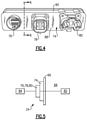
- FIG. 4 illustrates an example header plate with three example electrical connectors attached thereto.
- FIG. 5 is a schematic, cross-sectional view illustrating the arrangement of the header plate and electrical connectors relative to components inside and outside the battery pack.
- FIG. 6 is a cross-sectional, broken view taken along line 6 - 6 from FIG. 4 .
- FIG. 7 illustrates the example header plate without any electrical connectors.
- An example battery assembly includes a plate, which may be referred to as a header plate, configured to support an electrical connector.
- the plate includes aluminum (Al) alloy and is coated with a layer of ceramic material. This arrangement maintains the integrity of a seal between the plate and the electrical connector, in particular by resisting corrosion, and is particularly useful in corrosive environments such as those near a vehicle underbody.
- FIG. 1 schematically illustrates a powertrain 10 for an electrified vehicle 12 .
- HEV hybrid electric vehicle
- PHEVs plug-in hybrid electric vehicles
- BEVs battery electric vehicles
- the powertrain 10 is a power-split powertrain system that employs a first drive system and a second drive system.
- the first drive system includes a combination of an engine 14 and a generator 18 (i.e., a first electric machine).
- the second drive system includes at least a motor 22 (i.e., a second electric machine), the generator 18 , and a battery assembly 24 .
- the second drive system is considered an electric drive system of the powertrain 10 .
- the first and second drive systems generate torque to drive one or more sets of vehicle drive wheels 28 of the electrified vehicle 12 .
- a power-split configuration is shown, this disclosure extends to any hybrid or electric vehicle including full hybrids, parallel hybrids, series hybrids, mild hybrids or micro hybrids.
- the engine 14 which in one embodiment is an internal combustion engine, and the generator 18 may be connected through a power transfer unit 30 , such as a planetary gear set.
- a power transfer unit 30 such as a planetary gear set.
- the power transfer unit 30 is a planetary gear set that includes a ring gear 32 , a sun gear 34 , and a carrier assembly 36 .
- the generator 18 can be driven by the engine 14 through the power transfer unit 30 to convert kinetic energy to electrical energy.
- the generator 18 can alternatively function as a motor to convert electrical energy into kinetic energy, thereby outputting torque to a shaft 38 connected to the power transfer unit 30 . Because the generator 18 is operatively connected to the engine 14 , the speed of the engine 14 can be controlled by the generator 18 .
- the ring gear 32 of the power transfer unit 30 may be connected to a shaft 40 , which is connected to vehicle drive wheels 28 through a second power transfer unit 44 .
- the second power transfer unit 44 may include a gear set having a plurality of gears 46 .
- Other power transfer units may also be suitable.
- the gears 46 transfer torque from the engine 14 to a differential 48 to ultimately provide traction to the vehicle drive wheels 28 .
- the differential 48 may include a plurality of gears that enable the transfer of torque to the vehicle drive wheels 28 .
- the second power transfer unit 44 is mechanically coupled to an axle 50 through the differential 48 to distribute torque to the vehicle drive wheels 28 .
- the motor 22 can also be employed to drive the vehicle drive wheels 28 by outputting torque to a shaft 52 that is also connected to the second power transfer unit 44 .
- the motor 22 and the generator 18 cooperate as part of a regenerative braking system in which both the motor 22 and the generator 18 can be employed as motors to output torque.
- the motor 22 and the generator 18 can each output electrical power to the battery assembly 24 .
- the battery assembly 24 is an exemplary electrified vehicle battery.
- the battery assembly 24 may be a high voltage traction battery pack that includes a plurality of battery assemblies 25 (i.e., battery arrays or groupings of battery cells) capable of outputting electrical power to operate the motor 22 , the generator 18 , and/or other electrical loads of the electrified vehicle 12 .
- battery assemblies 25 i.e., battery arrays or groupings of battery cells
- Other types of energy storage devices and/or output devices can also be used to electrically power the electrified vehicle 12 .
- the electrified vehicle 12 has two basic operating modes.
- the electrified vehicle 12 may operate in an Electric Vehicle (EV) mode where the motor 22 is used (generally without assistance from the engine 14 ) for vehicle propulsion, thereby depleting the battery assembly 24 state of charge up to its maximum allowable discharging rate under certain driving patterns/cycles.
- EV Electric Vehicle
- the EV mode is an example of a charge depleting mode of operation for the electrified vehicle 12 .
- the state of charge of the battery assembly 24 may increase in some circumstances, for example due to a period of regenerative braking.
- the engine 14 is generally OFF under a default EV mode but could be operated as necessary based on a vehicle system state or as permitted by the operator.
- the electrified vehicle 12 may additionally operate in a Hybrid (HEV) mode in which the engine 14 and the motor 22 are both used for vehicle propulsion.
- HEV Hybrid
- the HEV mode is an example of a charge sustaining mode of operation for the electrified vehicle 12 .
- the electrified vehicle 12 may reduce the motor 22 propulsion usage in order to maintain the state of charge of the battery assembly 24 at a constant or approximately constant level by increasing the engine 14 propulsion usage.
- the electrified vehicle 12 may be operated in other operating modes in addition to the EV and HEV modes within the scope of this disclosure.
- FIG. 2 illustrates additional detail of the battery assembly 24 .
- the battery assembly 24 includes battery arrays, which can be described as groupings of battery cells, for supplying electrical power to various vehicle components.
- the battery assembly 24 could include a single battery array or multiple battery arrays. In other words, this disclosure is not limited to the specific configuration shown in FIG. 2 .
- Each battery array 56 A, 56 B includes a plurality of battery cells 58 that may be stacked side-by-side along a span length (i.e., the largest dimension) of each battery array 56 A, 56 B.
- the battery cells 58 are electrically connected to one another using busbar assemblies.
- the battery cells 58 are prismatic, lithium-ion cells.
- battery cells having other geometries (cylindrical, pouch, etc.) and/or other chemistries (nickel-metal hydride, lead-acid, etc.) could alternatively be utilized within the scope of this disclosure.
- An enclosure assembly 60 surrounds the battery arrays 56 A, 56 B.
- the enclosure assembly 60 includes a tray 62 and a cover 64 which establish a plurality of walls 66 that surround the interior 68 (i.e., area inside the walls 66 ).
- the enclosure assembly 60 may take any size, shape or configuration, and is not limited to the specific configuration of FIG. 2 .
- the enclosure assembly 60 defines an interior 68 for housing the battery arrays 56 A, 56 B and, potentially, any other components of the battery assembly 24 .
- FIG. 3 illustrates the battery assembly 24 mounted to the electrified vehicle 12 , and in particular mounted adjacent an underbody 70 of the electrified vehicle 12 .
- the battery assembly 24 is attached to sheet metal 72 forming a portion of an underside of a frame of the electrified vehicle 12 .
- the underbody 70 of the electrified vehicle 12 is a potentially corrosive environment due to potential exposure to the elements. While the battery assembly 24 is mounted adjacent the underbody of the electrified vehicle 12 , this disclosure extends to battery assemblies and header plates mounted in other areas of the electrified vehicle, including other corrosive environments.
- a plate 74 which may be referred to as a header plate, is connected to a wall 66 of the battery assembly 24 and configured to support at least one electrical connector relative to the battery assembly 24 .
- the plate 74 is connected to the wall 66 directly, or via a seal, such that it is substantially air and water tight.
- the plate 74 supports three electrical connectors 76 , 78 , 80 relative to the battery assembly 24 .
- the plate 74 and electrical connectors 76 , 78 , 80 are also shown in FIG. 4 .
- the electrical connectors 76 , 78 , 80 are electromechanical devices used to join electrical terminations and create electrical circuits.
- the electrical connectors 76 , 78 , 80 may be female or male components (i.e., sockets or plugs).
- the electrical connectors 76 , 78 , 80 are made of a plastic material in this example, but this disclosure is not limited to plastic electrical connectors.
- the plate 74 supports the electrical connectors 76 , 78 , 80 relative to the wall 66 , and the electrical connectors 76 , 78 , 80 each electrically connect a component 82 in the interior 68 of the battery assembly 24 to a component 84 outside the battery assembly 24 .
- the electrical connectors 76 , 78 , 80 electronically connect the battery assembly 24 to components such as a motor, an inverter, DC-to-DC converter, or another electronic component outside the battery assembly 24 .
- This disclosure is not limited to plates mounted to a battery assembly, however, and can extend to connections between other high voltage system components such as an inverter, charger, DC-to-DC converter, and/or electric motor. While electrical connectors are referred to herein, this disclosure could extend to fluid connectors configured to fluidly couple components inside the battery assembly 24 to components outside the battery assembly 24 .
- the plate 74 is formed of a single piece of aluminum (Al) alloy material. Further, the plate 74 is formed without any joints or seams. The plate 74 is also coated with a layer of ceramic material 86 ( FIG. 6 ). In this sense, the plate 74 consists of a seamless, aluminum (Al) alloy structure and a layer of ceramic material 86 .
- the plate 74 in this disclosure, includes a main body section 88 and a perimeter flange 90 .
- the perimeter flange 90 extends about the entirety of a perimeter of the main body section 88 and projects in a direction normal to a plane of the main body section 88 .
- the perimeter flange 90 directly contacts the wall 66 , in one example.
- a seal may be arranged between the perimeter flange 90 and the wall 66 .
- the main body section 88 covers one or more openings in the wall 66 and itself includes a plurality of openings 92 , 94 , 96 ( FIG. 7 ) configured to support the electrical connectors 76 , 78 , 80 , respectively.
- the openings 92 , 94 , 96 are sized and shaped to interface with the particular size and shape of the electrical connectors 76 , 78 , 80 .
- the openings 92 , 94 , 96 may be any shape. As shown, they are circular, rectangular, and ovular, respectively.
- the openings 92 , 94 , 96 may be configured to permit the electrical connectors 76 , 78 , 80 to snap-fit relative to the plate 74 or be attached to the plate 74 using fasteners, such as threaded fasteners.
- threaded openings 98 configured to receive threaded fasteners may be arranged relative to some of the openings 92 , 94 , 96 .
- a seal such as a rubber or ethylene propylene diene monomer (EPDM) O-ring, may be positioned between the plate 74 and one or more of the electrical connectors 76 , 78 , 80 .
- one or more of the electrical connectors 76 , 78 , 80 may be directly connected to the plate 74 without an intervening seal.
- the layer of ceramic material 86 is an electro ceramic coating (ECC) in one example.
- ECC electro ceramic coating
- the layer of ceramic material 86 completely coats at least the main body section 88 of the plate 74 .
- the layer of ceramic material 86 provides an effective seal between the plate 74 and the electrical connectors 76 , 78 , 80 .
- the layer of ceramic material 86 may be applied using a known technique, such as plasma deposition, and exhibits a thickness T of between 3 to 50 ⁇ m. In a particular example, the thickness T is about 8 ⁇ m. Such a thickness provides effective resistance to corrosion in particular when there is a seal such as an O-ring directly between the plate 74 and the electrical connectors 76 , 78 , 80 .
- plate 74 is made of A304, which is known as K-Alloy.
- K-Alloy is an aluminum (Al) alloy which includes a low percentage of copper (Cu) by weight.
- Al aluminum
- Al aluminum
- Cu copper
- the aluminum (Al) alloy plate effectively maintains seals with the electrical connectors 76 , 78 , 80 by resisting corrosion, and without being unduly expensive or difficult to manufacture.
- Other example aluminum (Al) alloys include ADC12, A380, ADC3, A356, and A413.
Landscapes
- Chemical & Material Sciences (AREA)
- Engineering & Computer Science (AREA)
- General Chemical & Material Sciences (AREA)
- Electrochemistry (AREA)
- Chemical Kinetics & Catalysis (AREA)
- Power Engineering (AREA)
- Mechanical Engineering (AREA)
- Transportation (AREA)
- Life Sciences & Earth Sciences (AREA)
- Sustainable Energy (AREA)
- Sustainable Development (AREA)
- Inorganic Chemistry (AREA)
- Manufacturing & Machinery (AREA)
- Aviation & Aerospace Engineering (AREA)
- Electric Propulsion And Braking For Vehicles (AREA)
- Ceramic Engineering (AREA)
- Materials Engineering (AREA)
Abstract
Description
Claims (16)
Priority Applications (3)
| Application Number | Priority Date | Filing Date | Title |
|---|---|---|---|
| US16/578,448 US11233363B2 (en) | 2019-09-23 | 2019-09-23 | Aluminum alloy header plate with ceramic coating for battery assembly |
| DE102020124713.3A DE102020124713A1 (en) | 2019-09-23 | 2020-09-22 | ALUMINUM ALLOY TOP PLATE WITH CERAMIC COATING FOR A BATTERY ASSEMBLY |
| CN202011005009.3A CN112537210A (en) | 2019-09-23 | 2020-09-22 | Aluminum alloy header plate with ceramic coating for battery assembly |
Applications Claiming Priority (1)
| Application Number | Priority Date | Filing Date | Title |
|---|---|---|---|
| US16/578,448 US11233363B2 (en) | 2019-09-23 | 2019-09-23 | Aluminum alloy header plate with ceramic coating for battery assembly |
Publications (2)
| Publication Number | Publication Date |
|---|---|
| US20210091380A1 US20210091380A1 (en) | 2021-03-25 |
| US11233363B2 true US11233363B2 (en) | 2022-01-25 |
Family
ID=74846461
Family Applications (1)
| Application Number | Title | Priority Date | Filing Date |
|---|---|---|---|
| US16/578,448 Expired - Fee Related US11233363B2 (en) | 2019-09-23 | 2019-09-23 | Aluminum alloy header plate with ceramic coating for battery assembly |
Country Status (3)
| Country | Link |
|---|---|
| US (1) | US11233363B2 (en) |
| CN (1) | CN112537210A (en) |
| DE (1) | DE102020124713A1 (en) |
Families Citing this family (6)
| Publication number | Priority date | Publication date | Assignee | Title |
|---|---|---|---|---|
| CN116569399A (en) * | 2021-09-07 | 2023-08-08 | 株式会社Lg新能源 | Battery module, battery pack and vehicle including battery pack |
| US12609410B2 (en) * | 2021-09-23 | 2026-04-21 | Lg Energy Solution, Ltd. | High heat-resistant connector, and battery module, battery pack, and vehicle including the same |
| KR102841062B1 (en) | 2021-10-08 | 2025-07-30 | 주식회사 엘지에너지솔루션 | Battery Module, Battery Pack, And Electronic Vehicle Including Same |
| WO2024036554A1 (en) * | 2022-08-18 | 2024-02-22 | 宁德时代新能源科技股份有限公司 | End cover assembly, battery cell, battery, and electric device |
| FR3146427A1 (en) * | 2023-03-09 | 2024-09-13 | Psa Automobiles Sa | MOTOR VEHICLE COMPRISING A DEVICE FOR CONNECTING A BATTERY TO AN ENGINE AND TO A CHARGING SOCKET, AND METHOD BASED ON SUCH A VEHICLE |
| CN116445760A (en) * | 2023-06-20 | 2023-07-18 | 宁德时代新能源科技股份有限公司 | Aluminum alloy ceramic composite material, preparation method thereof, battery pack and power utilization device |
Citations (15)
| Publication number | Priority date | Publication date | Assignee | Title |
|---|---|---|---|---|
| US2421719A (en) * | 1942-06-06 | 1947-06-03 | Western Electric Co | Vitreous enamelled article |
| US4472486A (en) * | 1983-05-06 | 1984-09-18 | Concorde Battery Corporation | Terminal support member |
| US5266053A (en) * | 1991-08-14 | 1993-11-30 | Alcatel Cit | Seal, in particular electromagnetic seal |
| US20090180265A1 (en) * | 2006-03-02 | 2009-07-16 | Lubomir Chlumsky | Electric Device Having a Plastic Plug Part Arranged on a Circuit Support |
| US20110300426A1 (en) * | 2009-02-24 | 2011-12-08 | Nissan Motor Co., Ltd., | Vehicle battery mounting structure |
| CN202721207U (en) | 2012-03-30 | 2013-02-06 | 覃美莲 | Totally-enclosed battery box |
| WO2014162963A1 (en) * | 2013-04-03 | 2014-10-09 | Necエナジーデバイス株式会社 | Battery module |
| US20150182996A1 (en) * | 2013-12-31 | 2015-07-02 | The United States Of America As Represented By The Secretary Of The Navy | Intergranular corrosion (igc) and intergranular stress corrosion cracking (igscc) resistance improvement method for metallic alloys |
| US20160376720A1 (en) * | 2015-06-29 | 2016-12-29 | GM Global Technology Operations LLC | Electro ceramic coated aluminum transmission components |
| US20170025663A1 (en) * | 2015-07-23 | 2017-01-26 | Lsis Co., Ltd. | External connector of vehicle battery pack |
| US20170033497A1 (en) | 2015-07-29 | 2017-02-02 | Industria Lombarda Materiale Elettrico I.L.M.E. S.P.A. | Plug connector housing protected against corrosion and erosion |
| CN107749457A (en) | 2016-11-18 | 2018-03-02 | 万向二三股份公司 | A kind of lithium ion battery of the ceramic coating containing positive pole |
| US20180269703A1 (en) * | 2016-02-11 | 2018-09-20 | The Noco Company | Battery connector device for a battery jump starting device |
| US20200059020A1 (en) * | 2016-10-26 | 2020-02-20 | Samsung Sdi Co., Ltd. | Connector for printed circuit board and battery system comprising printed circuit board and connector |
| US20200091483A1 (en) * | 2017-12-05 | 2020-03-19 | Nippon Light Metal Company, Ltd. | Aluminum alloy sheet for battery lids for molding integrated explosion-prevention valve, and method for producing same |
-
2019
- 2019-09-23 US US16/578,448 patent/US11233363B2/en not_active Expired - Fee Related
-
2020
- 2020-09-22 CN CN202011005009.3A patent/CN112537210A/en active Pending
- 2020-09-22 DE DE102020124713.3A patent/DE102020124713A1/en active Pending
Patent Citations (16)
| Publication number | Priority date | Publication date | Assignee | Title |
|---|---|---|---|---|
| US2421719A (en) * | 1942-06-06 | 1947-06-03 | Western Electric Co | Vitreous enamelled article |
| US4472486A (en) * | 1983-05-06 | 1984-09-18 | Concorde Battery Corporation | Terminal support member |
| US5266053A (en) * | 1991-08-14 | 1993-11-30 | Alcatel Cit | Seal, in particular electromagnetic seal |
| US20090180265A1 (en) * | 2006-03-02 | 2009-07-16 | Lubomir Chlumsky | Electric Device Having a Plastic Plug Part Arranged on a Circuit Support |
| US20110300426A1 (en) * | 2009-02-24 | 2011-12-08 | Nissan Motor Co., Ltd., | Vehicle battery mounting structure |
| CN202721207U (en) | 2012-03-30 | 2013-02-06 | 覃美莲 | Totally-enclosed battery box |
| WO2014162963A1 (en) * | 2013-04-03 | 2014-10-09 | Necエナジーデバイス株式会社 | Battery module |
| US20150182996A1 (en) * | 2013-12-31 | 2015-07-02 | The United States Of America As Represented By The Secretary Of The Navy | Intergranular corrosion (igc) and intergranular stress corrosion cracking (igscc) resistance improvement method for metallic alloys |
| US20160376720A1 (en) * | 2015-06-29 | 2016-12-29 | GM Global Technology Operations LLC | Electro ceramic coated aluminum transmission components |
| US9915007B2 (en) | 2015-06-29 | 2018-03-13 | GM Global Technology Operations LLC | Electro ceramic coated aluminum transmission components |
| US20170025663A1 (en) * | 2015-07-23 | 2017-01-26 | Lsis Co., Ltd. | External connector of vehicle battery pack |
| US20170033497A1 (en) | 2015-07-29 | 2017-02-02 | Industria Lombarda Materiale Elettrico I.L.M.E. S.P.A. | Plug connector housing protected against corrosion and erosion |
| US20180269703A1 (en) * | 2016-02-11 | 2018-09-20 | The Noco Company | Battery connector device for a battery jump starting device |
| US20200059020A1 (en) * | 2016-10-26 | 2020-02-20 | Samsung Sdi Co., Ltd. | Connector for printed circuit board and battery system comprising printed circuit board and connector |
| CN107749457A (en) | 2016-11-18 | 2018-03-02 | 万向二三股份公司 | A kind of lithium ion battery of the ceramic coating containing positive pole |
| US20200091483A1 (en) * | 2017-12-05 | 2020-03-19 | Nippon Light Metal Company, Ltd. | Aluminum alloy sheet for battery lids for molding integrated explosion-prevention valve, and method for producing same |
Non-Patent Citations (4)
| Title |
|---|
| "K-Alloy Properties", Dynacast, <https://www.dynacast.com/en/knowledge-center/material-information/die-cast-metals/aluminum-die-casting-metals/k-alloy> (Year: 2019). * |
| Knapp, Andrea; "Delphi's Innovative K-Alloy SP Now Available for Sand Casting and Permanent Mold Processes"; Thomas Net; Delphi Automotive PLC; Feb. 18, 2010 <https://news.thomasnet.com/companystory/delphi-s-innovative-k-alloy-sp-now-available-for-sand-casting-and-permanent-mold-processes-831761> (Year: 2010). * |
| Kukalis, John. "Battery Electric Vehicles Charge Ahead with Functional Coatings," Henkel Adhesive Technologies Blog—North America, Mar. 7, 2019, downloaded from henkeladhesivesna.com/blog/battery-electric-vehicles-charge-ahead-functional-coatings/ on Jun. 27, 2019. |
| Wally Huskonen, "Innovative Aluminum Diecasting Alloy Resists Corrosion"; Foundry Management and Technolody, Oct. 2, 2008, <https://www.foundrymag.com/issues-and-ideas/article/21925328/innovative-aluminum-diecasting-alloy-resists-corrosion> (Year: 2008). * |
Also Published As
| Publication number | Publication date |
|---|---|
| US20210091380A1 (en) | 2021-03-25 |
| CN112537210A (en) | 2021-03-23 |
| DE102020124713A1 (en) | 2021-03-25 |
Similar Documents
| Publication | Publication Date | Title |
|---|---|---|
| US11233363B2 (en) | Aluminum alloy header plate with ceramic coating for battery assembly | |
| US10717401B2 (en) | Terminal block assembly for electrified vehicles | |
| CN105280981B (en) | Battery pack ventilation system for electrified vehicles | |
| US10608222B2 (en) | Integrated modules for battery packs | |
| US10431860B2 (en) | Cold plate assembly for electrified vehicle batteries | |
| US10158106B2 (en) | Beam system for electrified vehicle battery packs | |
| US10823290B2 (en) | Plated sealing system for vehicle assembly | |
| US10804512B2 (en) | Compression limiters for electrified vehicle battery assemblies | |
| US20170194615A1 (en) | Battery cell separator having contoured profile | |
| CN107719144B (en) | Heat exchange plate assembly for vehicle battery | |
| US11114715B2 (en) | Enclosure assemblies with improved electromagnetic compatibility | |
| US11858363B2 (en) | Busbar assembly for an electrified vehicle and method of forming the same | |
| US12049142B2 (en) | Battery array mounting and supporting brackets | |
| US20190115574A1 (en) | Array frame mounting inserts for securing battery assemblies | |
| US11192439B2 (en) | Battery assembly with plate having compression limiting feature | |
| US10109823B2 (en) | Battery pack cover system | |
| US20210159471A1 (en) | Gasket adapter for battery assembly of electrified vehicle | |
| CN115882150A (en) | Attachment concept for a traction battery enclosure assembly | |
| CN106997969B (en) | Electronic device umbrella for electric vehicle battery pack | |
| CN116259899A (en) | Battery array design with multiple cooling side capability for traction battery pack |
Legal Events
| Date | Code | Title | Description |
|---|---|---|---|
| AS | Assignment |
Owner name: FORD GLOBAL TECHNOLOGIES, LLC, MICHIGAN Free format text: ASSIGNMENT OF ASSIGNORS INTEREST;ASSIGNORS:ATALA, MOHD;LAZARZ, KIMBERLY ANN;BARR, MICHAEL;SIGNING DATES FROM 20190919 TO 20190923;REEL/FRAME:050454/0777 |
|
| FEPP | Fee payment procedure |
Free format text: ENTITY STATUS SET TO UNDISCOUNTED (ORIGINAL EVENT CODE: BIG.); ENTITY STATUS OF PATENT OWNER: LARGE ENTITY |
|
| STPP | Information on status: patent application and granting procedure in general |
Free format text: NON FINAL ACTION MAILED |
|
| STPP | Information on status: patent application and granting procedure in general |
Free format text: RESPONSE TO NON-FINAL OFFICE ACTION ENTERED AND FORWARDED TO EXAMINER |
|
| STPP | Information on status: patent application and granting procedure in general |
Free format text: FINAL REJECTION MAILED |
|
| STPP | Information on status: patent application and granting procedure in general |
Free format text: RESPONSE AFTER FINAL ACTION FORWARDED TO EXAMINER |
|
| STPP | Information on status: patent application and granting procedure in general |
Free format text: NOTICE OF ALLOWANCE MAILED -- APPLICATION RECEIVED IN OFFICE OF PUBLICATIONS |
|
| STPP | Information on status: patent application and granting procedure in general |
Free format text: PUBLICATIONS -- ISSUE FEE PAYMENT VERIFIED |
|
| STCF | Information on status: patent grant |
Free format text: PATENTED CASE |
|
| FEPP | Fee payment procedure |
Free format text: MAINTENANCE FEE REMINDER MAILED (ORIGINAL EVENT CODE: REM.); ENTITY STATUS OF PATENT OWNER: LARGE ENTITY |
|
| LAPS | Lapse for failure to pay maintenance fees |
Free format text: PATENT EXPIRED FOR FAILURE TO PAY MAINTENANCE FEES (ORIGINAL EVENT CODE: EXP.); ENTITY STATUS OF PATENT OWNER: LARGE ENTITY |
|
| STCH | Information on status: patent discontinuation |
Free format text: PATENT EXPIRED DUE TO NONPAYMENT OF MAINTENANCE FEES UNDER 37 CFR 1.362 |
|
| FP | Lapsed due to failure to pay maintenance fee |
Effective date: 20260125 |