US11230985B2 - Control device of internal combustion engine, in-vehicle electronic control unit, machine learning system, control method of internal combustion engine, manufacturing method of electronic control unit, and output parameter calculation device - Google Patents
Control device of internal combustion engine, in-vehicle electronic control unit, machine learning system, control method of internal combustion engine, manufacturing method of electronic control unit, and output parameter calculation device Download PDFInfo
- Publication number
- US11230985B2 US11230985B2 US16/726,069 US201916726069A US11230985B2 US 11230985 B2 US11230985 B2 US 11230985B2 US 201916726069 A US201916726069 A US 201916726069A US 11230985 B2 US11230985 B2 US 11230985B2
- Authority
- US
- United States
- Prior art keywords
- neural network
- input
- input parameters
- network model
- output
- Prior art date
- Legal status (The legal status is an assumption and is not a legal conclusion. Google has not performed a legal analysis and makes no representation as to the accuracy of the status listed.)
- Active
Links
Images


Classifications
-
- F—MECHANICAL ENGINEERING; LIGHTING; HEATING; WEAPONS; BLASTING
- F02—COMBUSTION ENGINES; HOT-GAS OR COMBUSTION-PRODUCT ENGINE PLANTS
- F02D—CONTROLLING COMBUSTION ENGINES
- F02D41/00—Electrical control of supply of combustible mixture or its constituents
- F02D41/02—Circuit arrangements for generating control signals
- F02D41/14—Introducing closed-loop corrections
- F02D41/1401—Introducing closed-loop corrections characterised by the control or regulation method
- F02D41/1405—Neural network control
-
- F—MECHANICAL ENGINEERING; LIGHTING; HEATING; WEAPONS; BLASTING
- F02—COMBUSTION ENGINES; HOT-GAS OR COMBUSTION-PRODUCT ENGINE PLANTS
- F02D—CONTROLLING COMBUSTION ENGINES
- F02D29/00—Controlling engines, such controlling being peculiar to the devices driven thereby, the devices being other than parts or accessories essential to engine operation, e.g. controlling of engines by signals external thereto
- F02D29/02—Controlling engines, such controlling being peculiar to the devices driven thereby, the devices being other than parts or accessories essential to engine operation, e.g. controlling of engines by signals external thereto peculiar to engines driving vehicles; peculiar to engines driving variable pitch propellers
-
- F—MECHANICAL ENGINEERING; LIGHTING; HEATING; WEAPONS; BLASTING
- F02—COMBUSTION ENGINES; HOT-GAS OR COMBUSTION-PRODUCT ENGINE PLANTS
- F02D—CONTROLLING COMBUSTION ENGINES
- F02D41/00—Electrical control of supply of combustible mixture or its constituents
- F02D41/24—Electrical control of supply of combustible mixture or its constituents characterised by the use of digital means
- F02D41/2406—Electrical control of supply of combustible mixture or its constituents characterised by the use of digital means using essentially read only memories
- F02D41/2425—Particular ways of programming the data
- F02D41/2429—Methods of calibrating or learning
- F02D41/2451—Methods of calibrating or learning characterised by what is learned or calibrated
-
- F—MECHANICAL ENGINEERING; LIGHTING; HEATING; WEAPONS; BLASTING
- F02—COMBUSTION ENGINES; HOT-GAS OR COMBUSTION-PRODUCT ENGINE PLANTS
- F02D—CONTROLLING COMBUSTION ENGINES
- F02D41/00—Electrical control of supply of combustible mixture or its constituents
- F02D41/24—Electrical control of supply of combustible mixture or its constituents characterised by the use of digital means
- F02D41/2406—Electrical control of supply of combustible mixture or its constituents characterised by the use of digital means using essentially read only memories
- F02D41/2425—Particular ways of programming the data
- F02D41/2429—Methods of calibrating or learning
- F02D41/2477—Methods of calibrating or learning characterised by the method used for learning
-
- G—PHYSICS
- G05—CONTROLLING; REGULATING
- G05B—CONTROL OR REGULATING SYSTEMS IN GENERAL; FUNCTIONAL ELEMENTS OF SUCH SYSTEMS; MONITORING OR TESTING ARRANGEMENTS FOR SUCH SYSTEMS OR ELEMENTS
- G05B13/00—Adaptive control systems, i.e. systems automatically adjusting themselves to have a performance which is optimum according to some preassigned criterion
- G05B13/02—Adaptive control systems, i.e. systems automatically adjusting themselves to have a performance which is optimum according to some preassigned criterion electric
- G05B13/0265—Adaptive control systems, i.e. systems automatically adjusting themselves to have a performance which is optimum according to some preassigned criterion electric the criterion being a learning criterion
- G05B13/027—Adaptive control systems, i.e. systems automatically adjusting themselves to have a performance which is optimum according to some preassigned criterion electric the criterion being a learning criterion using neural networks only
-
- G—PHYSICS
- G06—COMPUTING OR CALCULATING; COUNTING
- G06N—COMPUTING ARRANGEMENTS BASED ON SPECIFIC COMPUTATIONAL MODELS
- G06N3/00—Computing arrangements based on biological models
- G06N3/02—Neural networks
- G06N3/04—Architecture, e.g. interconnection topology
- G06N3/045—Combinations of networks
-
- G—PHYSICS
- G06—COMPUTING OR CALCULATING; COUNTING
- G06N—COMPUTING ARRANGEMENTS BASED ON SPECIFIC COMPUTATIONAL MODELS
- G06N3/00—Computing arrangements based on biological models
- G06N3/02—Neural networks
- G06N3/04—Architecture, e.g. interconnection topology
- G06N3/0499—Feedforward networks
-
- G—PHYSICS
- G06—COMPUTING OR CALCULATING; COUNTING
- G06N—COMPUTING ARRANGEMENTS BASED ON SPECIFIC COMPUTATIONAL MODELS
- G06N3/00—Computing arrangements based on biological models
- G06N3/02—Neural networks
- G06N3/08—Learning methods
-
- G—PHYSICS
- G06—COMPUTING OR CALCULATING; COUNTING
- G06N—COMPUTING ARRANGEMENTS BASED ON SPECIFIC COMPUTATIONAL MODELS
- G06N3/00—Computing arrangements based on biological models
- G06N3/02—Neural networks
- G06N3/08—Learning methods
- G06N3/09—Supervised learning
-
- F—MECHANICAL ENGINEERING; LIGHTING; HEATING; WEAPONS; BLASTING
- F02—COMBUSTION ENGINES; HOT-GAS OR COMBUSTION-PRODUCT ENGINE PLANTS
- F02D—CONTROLLING COMBUSTION ENGINES
- F02D41/00—Electrical control of supply of combustible mixture or its constituents
- F02D41/02—Circuit arrangements for generating control signals
- F02D41/14—Introducing closed-loop corrections
- F02D41/1401—Introducing closed-loop corrections characterised by the control or regulation method
- F02D2041/1433—Introducing closed-loop corrections characterised by the control or regulation method using a model or simulation of the system
Definitions
- the disclosure relates to a control device of an internal combustion engine, an in-vehicle electronic control unit, a machine learning system, a control method of an internal combustion engine, a manufacturing method of an electronic control unit, and an output parameter calculation device.
- a predetermined output parameter is calculated based on a predetermined input parameter using a neural network model including an input layer, a hidden layer (intermediate layer), and an output layer (for example, Japanese Unexamined Patent Application Publication No. 2011-054200 (JP 2011-054200 A)).
- a parameter that correlates with the output parameter is used as the input parameter to be input to the input layer. Basically, since an information amount for calculating the output parameter is larger as the number of input parameters is larger, calculation accuracy of the output parameter is improved.
- the disclosure provides a control device of an internal combustion engine, an in-vehicle electronic control unit, a machine learning system, a control method of an internal combustion engine, a manufacturing method of an electronic control unit, and an output parameter calculation device that improve calculation accuracy of an output parameter without increasing types of input parameters when the output parameter is calculated based on the input parameters using a neural network model.
- the gist of the disclosure is as follows.
- a first aspect of the disclosure relates to a control device of an internal combustion engine including a parameter acquisition unit configured to acquire a plurality of input parameters, a calculation unit configured to calculate at least one output parameter based on the input parameters acquired by the parameter acquisition unit using a neural network model, and a controller configured to control the internal combustion engine based on the at least one output parameter calculated by the calculation unit.
- the neural network model includes a plurality of neural network units and an output layer that outputs the at least one output parameter based on outputs of the neural network units.
- Each of the neural network units includes one input layer and at least one intermediate layer.
- the neural network model is configured to input different combinations of input parameters selected from the input parameters to each of the input layers of the neural network units such that a total number of input parameters to be input to the neural network units is larger than the number of the input parameters.
- the number of the input parameters may be n.
- the neural network model may include n C k neural network units to which n C k combinations of input parameters selected from the input parameters are input, where n may be three or more and k may be two to n ⁇ 1.
- the first aspect of the disclosure may further include a learning unit configured to perform learning of the neural network model in a vehicle mounted with the internal combustion engine.
- the parameter acquisition unit may be configured to acquire the input parameters and the at least one output parameter.
- the learning unit may be configured to perform the learning of the neural network model using a training data set including a combination of the input parameters and the at least one output parameter acquired by the parameter acquisition unit.
- a second aspect of the disclosure relates to an in-vehicle electronic control unit including a parameter acquisition unit configured to acquire a plurality of input parameters, and a calculation unit configured to calculate at least one output parameter based on the input parameters acquired by the parameter acquisition unit using a neural network model transmitted from a server outside a vehicle to the vehicle.
- the neural network model includes a plurality of neural network units and an output layer that outputs the at least one output parameter based on outputs of the neural network units.
- Each of the neural network units includes one input layer and at least one intermediate layer.
- the neural network model is configured to input different combinations of input parameters selected from the input parameters to each of the input layers of the neural network units such that a total number of input parameters to be input to the neural network units is larger than the number of the input parameters.
- a third aspect of the disclosure relates to a machine learning system including an electronic control unit provided in a vehicle, a communication device provided in the vehicle, and a server outside the vehicle.
- the electronic control unit includes a parameter acquisition unit configured to acquire a plurality of input parameters and at least one output parameter and transmit the input parameters and the at least one output parameter to the server through the communication device, and a calculation unit configured to calculate the at least one output parameter based on the input parameters acquired by the parameter acquisition unit using a neural network model transmitted from the server.
- the server is configured to perform learning of the neural network model using a training data set including a combination of the input parameters and the at least one output parameter acquired by the parameter acquisition unit.
- the neural network model includes a plurality of neural network units and an output layer that outputs the at least one output parameter based on outputs of the neural network units.
- Each of the neural network units includes one input layer and at least one intermediate layer.
- the neural network model is configured to input different combinations of input parameters selected from the input parameters to each of the input layers of the neural network units such that a total number of input parameters to be input to the neural network units is larger than the number of the input parameters.
- a fourth aspect of the disclosure relates to a control method of an internal combustion engine including acquiring a plurality of input parameters, calculating at least one output parameter based on the input parameters using a neural network model, and controlling the internal combustion engine based on the at least one output parameter.
- the neural network model includes a plurality of neural network units and an output layer that outputs the at least one output parameter based on outputs of the neural network units.
- Each of the neural network units includes one input layer and at least one intermediate layer.
- the neural network model is configured to input different combinations of input parameters selected from the input parameters to each of the input layers of the neural network units such that a total number of input parameters to be input to the neural network units is larger than the number of the input parameters.
- a fifth aspect of the disclosure relates to a manufacturing method of an electronic control unit including performing learning of a neural network model using a training data set including a combination of measured values of a plurality of input parameters and measured values of at least one output parameter corresponding to the measured values, and mounting the neural network model in the electronic control unit.
- the neural network model includes a plurality of neural network units and an output layer that outputs the at least one output parameter based on outputs of the neural network units.
- Each of the neural network units includes one input layer and at least one intermediate layer.
- the neural network model is configured to input different combinations of input parameters selected from the input parameters to each of the input layers of the neural network units such that a total number of input parameters to be input to the neural network units is larger than the number of the input parameters.
- a sixth aspect of the disclosure relates to an output parameter calculation device including a parameter acquisition unit configured to acquire a plurality of input parameters, and a calculation unit configured to calculate at least one output parameter based on the input parameters acquired by the parameter acquisition unit using a neural network model.
- the neural network model includes a plurality of neural network units and an output layer that outputs the at least one output parameter based on outputs of the neural network units.
- Each of the neural network units includes one input layer and at least one intermediate layer.
- the neural network model is configured to input different combinations of input parameters selected from the input parameters to each of the input layers of the neural network units such that a total number of input parameters to be input to the neural network units is larger than the number of the input parameters.
- the output parameter when the output parameter is calculated based on the input parameters using the neural network model, it is possible to improve the calculation accuracy of the output parameter without increasing the types of input parameters.
- FIG. 1 is a diagram schematically showing an internal combustion engine to which a control device of the internal combustion engine according to a first embodiment is adapted;
- FIG. 2 is a functional block diagram of an electronic control unit (ECU) according to the first embodiment
- FIG. 3 is a diagram showing an example of a neural network having a simple configuration
- FIG. 4 is a diagram showing an example of the neural network according to the first embodiment
- FIG. 5 is a diagram showing an example of the neural network according to the first embodiment
- FIG. 6 is a graph showing a relationship between a degree of freedom of a neural network model and a determination coefficient of an output parameter
- FIG. 7 is a diagram schematically showing a configuration of a first neural network model according to the embodiment.
- FIG. 8 is a graph showing a relationship between the number of training data sets used for learning the neural network model and the determination coefficient of the output parameter
- FIG. 9 is a flowchart showing a control routine for controlling the internal combustion engine according to the first embodiment
- FIG. 10 is a diagram schematically showing a machine learning system according to a second embodiment.
- FIG. 11 is a functional block diagram of an ECU according to a fourth embodiment.
- FIG. 1 is a diagram schematically showing an internal combustion engine to which a control device of the internal combustion engine according to the first embodiment is adapted.
- An internal combustion engine 1 shown in FIG. 1 is a compression self-ignition internal combustion engine (diesel engine) and is mounted on a vehicle.
- the internal combustion engine 1 includes an engine body 10 , a fuel supply device 20 , an intake system 30 , an exhaust system 40 , and an exhaust gas recirculation (EGR) system 50 .
- the engine body 10 includes a cylinder block in which a plurality of cylinders 11 is formed, a cylinder head in which an intake port and an exhaust port are formed, and a crankcase. In the embodiment, the number of cylinders 11 is four.
- a piston is disposed in each cylinder 11 , and each cylinder 11 communicates with the intake port and the exhaust port.
- the cylinder head is provided with an intake valve configured to open and close the intake port and an exhaust valve configured to open and close the exhaust port.
- the fuel supply device 20 includes a fuel injection valve 21 , a common rail 22 , a fuel supply pipe 23 , a fuel pump 24 , and a fuel tank 25 .
- the fuel injection valve 21 is connected to the fuel tank 25 through the common rail 22 and the fuel supply pipe 23 .
- the fuel injection valve 21 is disposed on the cylinder head so as to directly inject fuel into a combustion chamber of each cylinder 11 .
- the fuel injection valve 21 is a so-called in-cylinder fuel injection valve.
- the fuel pump 24 that pressure-feeds the fuel in the fuel tank 25 is disposed in the fuel supply pipe 23 .
- the fuel pressure-fed by the fuel pump 24 is supplied to the common rail 22 through the fuel supply pipe 23 and directly injected from the fuel injection valve 21 into the combustion chamber of each cylinder 11 .
- a pressure of the fuel in the common rail 22 is adjusted by changing an output of the fuel pump 24 .
- a so-called multistage injection is performed by the fuel injection valve 21 . Specifically, two pilot injections (a first pilot injection and a second pilot injection) and one main injection are performed in one cycle.
- the intake system 30 includes the intake port, an intake manifold 31 , an intake pipe 32 , an air cleaner 33 , a compressor 34 of a turbocharger 5 , an intercooler 35 , and a throttle valve 36 .
- the intake port, the intake manifold 31 , and the intake pipe 32 form an intake passage that guides air into the cylinder 11 .
- each cylinder 11 communicates with the air cleaner 33 through the intake manifold 31 and the intake pipe 32 .
- the compressor 34 that compresses and discharges intake air that flows through the intake pipe 32 and the intercooler 35 that cools the air compressed by the compressor 34 are provided in the intake pipe 32 .
- the throttle valve 36 can be rotated by a throttle valve drive actuator 37 to change an opening area of the intake passage.
- the exhaust system 40 includes the exhaust port, an exhaust manifold 41 , an exhaust pipe 42 , a turbine 43 of the turbocharger 5 , and a diesel particulate filter (DPF) 44 .
- the exhaust port, the exhaust manifold 41 and the exhaust pipe 42 form an exhaust passage for exhausting exhaust gas generated by combustion of an air-fuel mixture in the combustion chamber.
- each cylinder 11 communicates with the DPF 44 through the exhaust manifold 41 and the exhaust pipe 42 .
- the exhaust pipe 42 is provided with a turbine 43 rotatably driven by the energy of the exhaust gas.
- the turbine 43 is rotatably driven, the compressor 34 rotates accompanying the rotation and thus the intake air is compressed.
- the turbine 43 is provided with a variable nozzle. When an opening degree of the variable nozzle is changed, a flow velocity of the exhaust gas to be supplied to a turbine blade of the turbine 43 changes. As a result, a rotational speed of the turbine 43 changes.
- the DPF 44 collects particulate matter (PM) in the exhaust gas.
- the exhaust system 40 may include another exhaust gas control device instead of or in addition to the DPF 44 .
- another exhaust gas control device are a selective reduction type NOx reduction catalyst (selective catalytic reduction (SCR) catalyst), a NOx storage reduction catalyst, and an oxidation catalyst.
- SCR selective catalytic reduction
- the EGR system 50 supplies a part of the exhaust gas discharged from the engine body 10 to the exhaust passage to the intake passage.
- the EGR system 50 includes an EGR pipe 51 , an EGR control valve 52 , and an EGR cooler 53 .
- the EGR pipe 51 is connected to the exhaust manifold 41 and the intake manifold 31 and allows the exhaust manifold 41 and the intake manifold 31 to communicate with each other.
- the EGR pipe 51 is provided with the EGR cooler 53 that cools the EGR gas flowing in the EGR pipe 51 .
- the EGR pipe 51 is provided with the EGR control valve 52 that can change the opening area of an EGR passage formed by the EGR pipe 51 .
- the opening degree of the EGR control valve 52 is controlled to adjust a flow rate of the EGR gas to be recirculated from the exhaust manifold 41 to the intake manifold 31 .
- an EGR rate changes.
- the EGR rate is a ratio of an EGR gas amount to a total gas amount to be supplied into the cylinder 11 (sum of a fresh air amount and the EGR gas amount).
- the configuration of the internal combustion engine 1 is not limited to the above configuration. Therefore, the specific configuration of the internal combustion engine such as the cylinder arrangement, the fuel injection mode, the intake and exhaust system configuration, the valve mechanism configuration, the turbocharger configuration, and the presence or absence of the turbocharger may be different from the configuration shown in FIG. 1 .
- a vehicle mounted with the internal combustion engine 1 is provided with an electronic control unit (ECU) 61 .
- ECU electronice control unit
- Various controls of the internal combustion engine 1 are executed by the ECU 61 based on outputs of various sensors provided in the internal combustion engine 1 .
- the ECU 61 is an example of the control device of the internal combustion engine. In the embodiment, one ECU 61 is provided, but a plurality of ECUs may be provided for each function.
- the ECU 61 is configured of a digital computer and includes a memory 63 , a processor 65 , an input port 66 , and an output port 67 that are connected to each other through a bidirectional bus 62 .
- the memory 63 includes a volatile memory (for example, RAM) and a non-volatile memory (for example, ROM) and stores a program executed by the processor 65 , various pieces of data used when various processes are executed by the processor 65 , and the like.
- the outputs of various sensors are input to the input port 66 .
- the outputs of an air flow meter 71 , an intake air temperature sensor 72 , an intake air pressure sensor 73 , a fuel pressure sensor 74 , and a load sensor 78 are input to the input port 66 through a corresponding analog to digital (AD) converter 68 .
- AD analog to digital
- the air flow meter 71 is disposed in the intake pipe 32 between the air cleaner 33 and the compressor 34 and measures the flow rate of air (fresh air) in the intake pipe 32 .
- the intake air temperature sensor 72 is disposed in the intake manifold 31 and measures the temperature of the intake air (fresh air and EGR gas in the embodiment) in the intake manifold 31 .
- the intake air pressure sensor 73 is disposed in the intake manifold 31 and measures the pressure of intake air in the intake manifold 31 .
- the fuel pressure sensor 74 is disposed on the common rail 22 and measures the pressure of the fuel in the common rail 22 , that is, the pressure of the fuel to be supplied to the fuel injection valve 21 .
- the load sensor 78 is connected to an accelerator pedal 77 provided in the vehicle and generates an output voltage proportional to a depression amount of the accelerator pedal 77 .
- the processor 65 calculates an engine load based on the output of the load sensor 78 .
- the input port 66 is connected to a crank angle sensor 79 that generates an output pulse every time a crankshaft rotates, for example, 10° and receives the output pulse.
- the processor 65 measures an engine speed based on the output of the crank angle sensor 79 .
- the output port 67 is connected to various actuators of the internal combustion engine 1 through a corresponding drive circuit 69 .
- the output port 67 is connected to the variable nozzle of the turbine 43 , the fuel injection valve 21 , the fuel pump 24 , the throttle valve drive actuator 37 , and the EGR control valve 52 .
- the ECU 61 outputs a control signal from the output port 67 to control the various actuators.
- FIG. 2 is a functional block diagram of the ECU 61 in the first embodiment.
- the ECU 61 includes a parameter acquisition unit 81 , a calculation unit 82 , and a controller 83 .
- the parameter acquisition unit 81 , the calculation unit 82 , and the controller 83 are functional blocks that are realized when the processor 65 of the ECU 61 executes the program stored in the memory 63 of the ECU 61 .
- the parameter acquisition unit 81 acquires a plurality of input parameters.
- the calculation unit 82 calculates at least one output parameter based on the input parameters acquired by the parameter acquisition unit 81 using a neural network model.
- the controller 83 controls the internal combustion engine 1 based on the at least one output parameter calculated by the calculation unit 82 .
- FIG. 3 is a diagram showing an example of the neural network model having a simple configuration.
- a circle in FIG. 3 represents an artificial neuron.
- the artificial neuron is commonly referred to as a node or a unit (referred to as “nodes” in the specification).
- the hidden layer is also referred to as an intermediate layer.
- An input is output as it is at each node of the input layer.
- the activation function is, for example, a sigmoid function 6 .
- a total input value u( ⁇ z ⁇ w+b) is calculated using weight w and bias b corresponding to each of the output values or a total input value u( ⁇ z ⁇ w) is calculated using solely weight w corresponding to each of the output values at the node of the output layer.
- an identity function is used as an activation function at the node of the output layer.
- the total input value u calculated at the node of the output layer is output as it is as the output value y from the node of the output layer.
- a value of each weight w and a value of each bias b in the neural network model are learned using an error back-propagation method. Since the error back-propagation method is well known, an outline of the error back-propagation method will be briefly described below. Since the bias b is a kind of the weight w, the bias b is one of the weights w in the following description.
- ⁇ (L) can be represented by the following equation (K is the number of nodes in an L+1 layer).
- a first term ( ⁇ E/ ⁇ u (L+1) ) on the right side of the above equation (3) is ⁇ (L+1) .
- ⁇ (L) is represented by the following equation.
- a training data set including a certain input value x and correct answer data y t of an output value corresponding to the input value x is used.
- the neural network model as described above includes one input layer, and the different types of input parameters (input values) correlated with the output parameter (output value) output from the output layer are input to each node of the input layer.
- the intermediate state quantities generated from the input parameters are sequentially converted in the intermediate layer, and finally the output parameter is output from the output layer.
- the neural network model includes a plurality of input layers in order to increase the number of apparent input parameters.
- the neural network model includes a plurality of neural network units and an output layer that outputs at least one output parameter based on outputs of the neural network units.
- Each of the neural network units includes one input layer and at least one intermediate layer.
- the neural network units have, for example, the same configuration (number of nodes of the input layer, number of intermediate layers, and number of nodes of each intermediate layer).
- a set of input parameters including different types of input parameters is input to the input layers.
- similar intermediate state quantities are generated in the neural network units. For this reason, it is impossible to increase the expressive power of the neural network model and thus to improve the calculation accuracy of the output parameter.
- the neural network model In the neural network model according to the embodiment, different combinations of input parameters selected from the input parameters are input to each of the input layers of the neural network units such that the total number of input parameters to be input to the neural network units is larger than the number of the input parameters acquired by the parameter acquisition unit 81 .
- different intermediate state quantities are generated in the neural network units, and the output parameter is output from a plurality of intermediate state quantities. For this reason, it is possible to increase the expressive power of the neural network model and thus to improve the calculation accuracy of the output parameter without increasing the types of input parameters.
- the neural network model when the number of the input parameters is n, the neural network model includes n C k neural network units to which n C k combinations of input parameters selected from the input parameters acquired by the parameter acquisition unit 81 are input.
- an equal number (k) of input parameters are input to each neural network unit.
- N is 3 or more and k is 2 to n ⁇ 1 such that the different combinations of input parameters are input to each neural network unit. In this manner, it is possible to easily generate the neural network model capable of generating the different intermediate state quantities by selecting the number of neural network units and the combinations of input parameters.
- the neural network model is a regression model that predicts at least one output parameter from the input parameters.
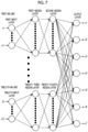
- FIG. 4 is a diagram showing an example of the neural network model in the first embodiment.
- the number of input parameters to be acquired by the parameter acquisition unit 81 is three (x 1 , x 2 , and x 3 ).
- the types of the three input parameters are different from each other.
- the neural network model includes a first neural network unit (referred to as a “first NN unit” in the specification), a second neural network unit (referred to as a “second NN unit” in the specification), a third neural network unit (referred to as a “third NN unit” in the specification), and an output layer. That is, the neural network model includes three neural network units.
- the first neural network unit includes one input layer (a first input layer) and two hidden layers (a first hidden layer and a second hidden layer) directly or indirectly coupled to the input layer.
- a set of input parameters (x 1 and x 2 ) selected from a plurality of input parameters (x 1 , x 2 , and x 3 ) is input to the first input layer.
- the number of nodes of the input layer is equal to the number of input parameters to be input to the input layer. For this reason, the first input layer has two nodes.
- the first hidden layer is coupled to the first input layer, and outputs of the first input layer are input to the first hidden layer. Specifically, nodes of the first hidden layer are respectively coupled to all the nodes of the first input layer. For this reason, the outputs of all the nodes of the first input layer are respectively input to the nodes of the first hidden layer.
- the first hidden layer has four nodes.
- the second hidden layer is coupled to the first hidden layer, and outputs of the first hidden layer are input to the second hidden layer. Specifically, nodes of the second hidden layer are respectively coupled to all the nodes of the first hidden layer. For this reason, the outputs of all the nodes of the first hidden layer are respectively input to the nodes of the second hidden layer.
- the second hidden layer has four nodes.
- the second neural network unit has the same configuration as the first neural network unit and includes one input layer (a second input layer) and two hidden layers (a third hidden layer and a fourth hidden layer) directly or indirectly coupled to the input layer.
- a set of input parameters (x 1 and x 3 ) selected from the input parameters (x 1 , x 2 , and x 3 ) are input to the second input layer.
- the third neural network unit has the same configuration as the first neural network unit and includes one input layer (a third input layer) and two hidden layers (a fifth hidden layer and a sixth hidden layer) directly or indirectly coupled to the input layer.
- a set of input parameters (x 2 , and x 3 ) selected from the input parameters (x 1 , x 2 , and x 3 ) are input to the third input layer.
- the output layer outputs an output parameter y based on the outputs of the first to third neural network units. For this reason, the output layer is coupled to the first to third neural network units, and the outputs of the first to third neural network units are input to the output layer.
- the output layer is coupled to the second hidden layer of the first neural network unit, the fourth hidden layer of the second neural network unit, and the sixth hidden layer of the third neural network unit. That is, a node of the output layer is coupled to all the nodes of the second hidden layer, the fourth hidden layer, and the sixth hidden layer. For this reason, the outputs of all the nodes of the second hidden layer, the fourth hidden layer, and the sixth hidden layer are input to the node of the output layer.
- the number of nodes of the output layer is equal to the number of output parameters to be output from the output layer. In the example of FIG. 4 , the output layer outputs one output parameter y and has one node.
- a combination of input parameters (x 1 and x 2 ) to be input to the first input layer of the first neural network unit, a combination of input parameters (x 1 and x 3 ) to be input to the second input layer of the second neural network unit, and a combination of input parameters (x 2 , and x 3 ) to be input to the third input layer of the third neural network unit are different from each other.
- the first to third neural network units respectively have independent configurations. That is, there are no nodes coupled to each other between the different neural network units. For this reason, different intermediate state quantities are generated in each neural network unit, and output parameters are output based on the three intermediate state quantities. Therefore, it is possible to increase the expressive power of the neural network model and thus to improve the calculation accuracy of the output parameter without increasing the types of input parameters.
- the number of neural network units may be two or more.
- the first neural network unit, the second neural network unit, or the third neural network unit may be omitted.
- the neural network units may have different configurations.
- the number of input parameters to be input to each input layer may be different. That is, the number of nodes in each input layer may be different.
- the three input parameters (x 1 , x 2 , and x 3 ) may be input to the third input layer, and the third input layer may have three nodes.
- the number of hidden layers in each neural network unit may be one or more. Further, the number of hidden layers in each neural network unit may be different. For example, the first neural network unit may include three hidden layers.
- the number of nodes in each hidden layer may be one or more. Further, the number of nodes in each hidden layer may be different. For example, the first hidden layer may have eight nodes.
- the number of output parameters output from the output layer may be two or more. That is, the output layer may have two or more nodes.
- the neural network model may further include a fully coupled layer coupled to the output layer, and the neural network units may be coupled to the output layer through the fully coupled layer.
- the number of nodes of fully coupled layer may be one or more.
- the learning of the neural network model (that is, setting of the weight w and the bias b) is performed before the neural network model is mounted on the vehicle.
- a training data set including a combination of measured values of the input parameters and measured values (correct answer data) of at least one output parameter corresponding to the measured values is used.
- the measured values of the input parameters and the output parameter are acquired in advance using, for example, an engine bench, and the training data set is created in advance by combining the corresponding measured values.
- the weight w and the bias b in the neural network model are repeatedly updated by the error back-propagation method described above using a plurality of training data sets.
- the neural network is learned and a learned neural network model is generated.
- the learning of the neural network model is performed using, for example, a computer (for example, a computer mounted with a graphics processing unit (GPU)) installed in a production factory or the like.
- the generated learned neural network model is mounted on the ECU 61 provided in the vehicle before the vehicle is shipped. That is, information (model structure, weight w, bias b, and the like) on the learned neural network model is stored in the memory 63 of the ECU 61 or another storage device provided in the vehicle.
- FIG. 6 is a graph showing a relationship between a degree of freedom of the neural network model and a determination coefficient of the output parameter.
- the degree of freedom of the neural network model indicates the total number of weights and biases in the neural network model. For this reason, the degree of freedom of the neural network model is larger as the number of input layers, the number of nodes of the input layer, the number of hidden layers, and the number of nodes of the hidden layers are larger.
- a determination coefficient R 2 of the output parameter is calculated by the following equation and takes a value of zero to one.
- the calculation accuracy of the output parameter is higher as the determination coefficient R 2 of the output parameter is closer to one.
- R 2 (sum of deviation squares of calculated values of output parameters)/(sum of deviation squares of measured values of output parameters), where the calculated values of output parameters are values output by the learned neural network model and the measured values of output parameters are values actually measured using a sensor or the like.
- results using a learned first neural network model according to the embodiment are plotted with diamonds, and results using the learned neural network model in a comparative example are plotted with squares.
- the number above each data point indicates the number of intermediate layers.
- FIG. 6 shows the results when the number of intermediate layers is changed from one to five in each neural network model.
- FIG. 7 is a diagram schematically showing a configuration of the first neural network model according to the embodiment.
- FIG. 7 shows the configuration of the first neural network model when the number of intermediate layers is two.
- the target of the first neural network model is the internal combustion engine 1 .
- the output layer has seven nodes and outputs seven types of output parameters y 1 to y 7 relating to an operation state of the internal combustion engine 1 .
- the y 1 is output torque of the internal combustion engine 1 .
- the y 2 is a sound pressure of a combustion sound.
- the y 3 is a crank angle (CA50) at which a combustion ratio becomes 50%.
- the y 4 is a nitrogen oxide (NOx) concentration in the exhaust gas.
- the y 5 is a carbon monoxide (CO) concentration in the exhaust gas.
- the y 6 is a hydrocarbon (HC) concentration in the exhaust gas.
- the y 7 is a smoke concentration in the exhaust gas.
- the x 1 is a fuel injection amount in a main injection.
- the x 2 is a fuel injection timing in the main injection.
- the x 3 is a fuel injection amount in a first pilot injection.
- the x 4 is a fuel injection timing in the first pilot injection.
- the x 5 is a fuel injection amount in a second pilot injection.
- the x 6 is a fuel injection timing in the second pilot injection.
- the x 7 is a fuel injection pressure.
- the x 8 is an intake air temperature.
- the x 9 is an intake air pressure.
- the x 10 is the EGR rate.
- the x 11 is the fresh air amount.
- the x 12 is an amount of gas flowing into the cylinder 11 .
- the values of the input parameters are, for example, measured by a sensor or the like as described below or calculated by the ECU 61 .
- the x 1 to x 6 are calculated based on a command value to be output from the ECU 61 to the fuel injection valve 21 .
- the x 7 is calculated based on an output of the fuel pressure sensor 74 .
- the x 8 is measured by the intake air temperature sensor 72 .
- the x 9 is measured by the intake air pressure sensor 73 .
- the x 10 is calculated based on a command value to be output from the ECU 61 to the EGR control valve 52 .
- the x 11 is measured by the air flow meter 71 .
- the x 12 is calculated based on an output of the air flow meter 71 and the command value to be output from the ECU 61 to the EGR control valve 52 .
- the neural network model in the comparative example has a simple configuration as shown in FIG. 3 , and outputs seven types of output parameters from the above 12 types of input parameters. Therefore, the neural network model in the comparative example includes an input layer having 12 nodes and an output layer having seven nodes.
- the number of nodes of the intermediate layer is set such that the degrees of freedom of the neural network models are equal when the number of intermediate layers is the same.
- the determination coefficient of the output parameter is calculated as an average value of the determination coefficients of the seven types of output parameters (y 1 to y 7 ).
- the first neural network model has a larger determination coefficient of the output parameter with respect to the degree of freedom of the neural network model than that in the comparative example. Therefore, the first neural network model has higher calculation accuracy of the output parameter than the neural network model in the comparative example.
- the results using a learned second neural network model according to the embodiment are plotted with circles, and the results using a learned third neural network model in the embodiment are plotted with triangles.
- the second neural network model and the third neural network model solely the results when the number of intermediate layers is two are shown.
- the neural network model includes n C k neural network units to which n C k combinations of input parameters are input, k can be set to any number from 2 to n ⁇ 1.
- FIG. 8 is a graph showing a relationship between the number of training data sets used for learning the neural network model and the determination coefficient of the output parameter.
- results using the learned first neural network model according to the embodiment are plotted with diamonds
- results using the learned neural network model in the comparative example are plotted with squares.
- Each of the first neural network model and the neural network model in the comparative example has three intermediate layers.
- the number of training data sets needed to obtain the same determination coefficient in the first neural network model is smaller than that in the neural network model in the comparative example. Therefore, in the neural network model in the embodiment, it is possible to reduce the number of training data sets needed to obtain predetermined calculation accuracy of the output parameter and thus to reduce a learning time of the neural network model.
- FIG. 9 is a flowchart showing a control routine for controlling the internal combustion engine according to the first embodiment.
- the control routine of FIG. 9 is repeatedly executed by the ECU 61 at a predetermined execution interval.
- the predetermined execution interval is, for example, a time of one cycle of the internal combustion engine 1 .
- the parameter acquisition unit 81 acquires the input parameters to be input to the neural network model.
- the input parameters are mutually different types of parameters, for example, parameters relating to the operation state of the internal combustion engine 1 .
- the input parameters are measured by the sensor or the like or calculated by the ECU 61 according to the types of the input parameters.
- the calculation unit 82 calculates at least one output parameter based on the input parameters acquired by the parameter acquisition unit 81 using the neural network model.
- the at least one output parameter is, for example, a parameter relating to the operation state of the internal combustion engine 1 .
- the neural network model includes the neural network units and the output layer that outputs the at least one output parameter based on the outputs of the neural network units.
- the calculation unit 82 inputs the different combinations of input parameters selected from the input parameters acquired by the parameter acquisition unit 81 to the neural network units to cause the neural network model to output the output parameter.
- step S 103 the controller 83 controls the internal combustion engine 1 based on the at least one output parameter calculated by the calculation unit 82 . Specifically, the controller 83 controls the internal combustion engine 1 such that the output parameter is included in a predetermined target range. For example, when the at least one output parameter includes the NOx concentration in the exhaust gas, the controller 83 causes the opening degree of the EGR control valve 52 to increase such that the NOx concentration decreases when a predicted value of the NOx concentration calculated by the calculation unit 82 is higher than the target range.
- the control routine ends.
- a configuration and control of the electronic control unit used in a machine learning system according to a second embodiment are basically the same as those of the electronic control unit in the first embodiment.
- the neural network model is learned in a server outside the vehicle, and the learned neural network model is transmitted from the server to the vehicle.
- the learned neural network model is transmitted from the server to the vehicle.
- FIG. 10 is a diagram schematically showing the machine learning system according to the second embodiment.
- a machine learning system 300 includes the electronic control unit (ECU) 61 and a communication device 91 which are provided in a vehicle 100 and a server 200 outside the vehicle 100 . Similar to the first embodiment, as shown in FIG. 2 , the ECU 61 includes the parameter acquisition unit 81 , the calculation unit 82 , and the controller 83 .
- the ECU 61 and the communication device 91 are communicably connected to each other through an in-vehicle network compliant with a standard such as a controller area network (CAN).
- the communication device 91 is communicable with the server 200 through a communication network and is, for example, a data communication module (DCM).
- DCM data communication module
- the communication between the communication device 91 and the server 200 is performed by wireless communication compliant with various communication standards.
- the server 200 includes a communication interface 210 , a storage device 230 , and a processor 220 .
- the communication interface 210 and the storage device 230 are connected to the processor 220 through signal lines.
- the server 200 may further include an input device such as a keyboard and a mouse, an output device such as a display, and the like.
- the communication interface 210 has an interface circuit for connecting the server 200 to the communication device 91 of the vehicle 100 through the communication network.
- the storage device 230 is configured of, for example, a hard disk drive (HDD), a solid state drive (SDD), an optical recording medium, a semiconductor memory such as a random access memory (RAM), and the like.
- the storage device 230 stores various pieces of data. Specifically, the storage device 230 stores a training data set used for learning the neural network model and a computer program for performing the learning of the neural network model.
- the training data set includes a combination of measured values of a plurality of input parameters and measured values of at least one output parameter corresponding to the measured values.
- the measured values of the input parameters and the output parameter are acquired in advance using, for example, the engine bench, and the training data set is created in advance by combining the corresponding measured values.
- the measured values of the input parameters and the output parameter may be acquired by another vehicle different from the vehicle 100 and transmitted to the server 200 from a communication device provided in another vehicle.
- the server 200 learns the neural network using the training data set and generates a learned neural network model. Specifically, the server 200 repeatedly updates weight w and bias b of the neural network by using the error back-propagation method described above using a plurality of training data sets. As a result, the weight w and the bias b of the neural network converge to appropriate values, and the learned neural network model is generated.
- the neural network model in the second embodiment has a configuration similar to that in the first embodiment (for example, refer to FIGS. 4, 5, and 7 ).
- the learned neural network model is transmitted from the server 200 to the ECU 61 of the vehicle 100 through the communication interface 210 of the server 200 and the communication device 91 of the vehicle 100 .
- information (model structure, weight w, bias b, and the like) on the learned neural network model is stored in the memory 63 of the ECU 61 or another storage device provided in the vehicle 100 .
- the calculation unit 82 of the ECU 61 calculate the at least one output parameter based on the input parameters using the learned neural network model transmitted from the server 200 to the vehicle 100 .
- the control routine of FIG. 9 is executed similar to the first embodiment, and the controller 83 controls the internal combustion engine 1 based on the at least one output parameter calculated by the calculation unit 82 .
- a configuration and control of a machine learning system according to a third embodiment are basically the same as the machine learning system according to the second embodiment. For this reason, hereinafter, the third embodiment of the disclosure will be described with a focus on differences from the second embodiment.
- the neural network model is learned in a server outside a vehicle, and the learned neural network model is transmitted from the server to the vehicle.
- measured values of input parameter and output parameter are acquired in the vehicle in order to create a training data set.
- the machine learning system 300 includes the electronic control unit (ECU) 61 and the communication device 91 which are provided in the vehicle 100 and the server 200 outside the vehicle 100 .
- the ECU 61 includes the parameter acquisition unit 81 , the calculation unit 82 , and the controller 83 .
- the parameter acquisition unit 81 acquires a plurality of input parameters and at least one output parameter used in the neural network model.
- the input parameters and the at least one output parameter are measured by a sensor or the like or calculated by the ECU 61 according to the types of parameters.
- a torque sensor is disposed on an output shaft (crankshaft) of the internal combustion engine 1 and the output torque of the internal combustion engine 1 is measured by the torque sensor.
- the parameter acquisition unit 81 transmits the input parameters and the at least one output parameter to the server 200 through the communication device 91 .
- a combination of the input parameters and the at least one output parameter transmitted to the server 200 is stored in the storage device 230 of the server 200 as the training data set.
- the server 200 learns a neural network using the training data set including the combination of the input parameters and the at least one output parameter acquired by the parameter acquisition unit 81 and generates the learned neural network model. Specifically, the server 200 repeatedly updates weight w and bias b of the neural network by using the error back-propagation method described above using the training data sets. As a result, the weight w and the bias b of the neural network converge to appropriate values, and the learned neural network model is generated.
- the server 200 transmits the learned neural network model to the ECU 61 of the vehicle 100 .
- the calculation unit 82 of the ECU 61 calculate the at least one output parameter based on the input parameters using the learned neural network model transmitted from the server 200 to the vehicle 100 .
- the control routine of FIG. 9 is executed similar to the first embodiment, and the controller 83 controls the internal combustion engine 1 based on the at least one output parameter calculated by the calculation unit 82 .
- a configuration and control of a control device of an internal combustion engine according to a fourth embodiment are basically the same as those of the control device of the internal combustion engine in the first embodiment. For this reason, hereinafter, the fourth embodiment of the disclosure will be described with a focus on differences from the first embodiment.
- measured values of input parameters and output parameters are acquired in a vehicle in order to create a training data set.
- learning of the neural network model is performed in the vehicle. As a result, it is possible to efficiently perform the learning of the neural network model in the vehicle without using a server or the like.
- FIG. 11 is a functional block diagram of the ECU 61 in the fourth embodiment.
- the ECU 61 includes a learning unit 84 in addition to the parameter acquisition unit 81 , the calculation unit 82 , and the controller 83 .
- the parameter acquisition unit 81 acquires a plurality of input parameters and at least one output parameter used in the neural network model. A combination of the input parameters and the at least one output parameter acquired by the parameter acquisition unit 81 is stored as the training data set in the memory 63 of the ECU 61 or another storage device provided in the vehicle.
- the learning unit 84 learns a neural network using the training data set including the combination of the input parameters and the at least one output parameter acquired by the parameter acquisition unit 81 and generates a learned neural network model. Specifically, the learning unit 84 repeatedly updates weight w and bias b of the neural network by using the error back-propagation method described above using a plurality of training data sets. As a result, the weight w and the bias b of the neural network converge to appropriate values, and the learned neural network model is generated.
- the calculation unit 82 calculates the at least one output parameter based on the input parameters using the learned neural network model. As a result, it is possible to obtain a predicted value of the output parameter corresponding to the input parameter having a predetermined value before the output parameter is measured by a sensor or the like.
- the control routine of FIG. 9 is executed similar to the first embodiment, and the controller 83 controls the internal combustion engine 1 based on the at least one output parameter calculated by the calculation unit 82 .
- the target of the neural network model used in an in-vehicle electronic control unit may be anything relating to the vehicle other than the internal combustion engine 1 described above.
- the target of the neural network model used in the in-vehicle electronic control unit may be a spark ignition internal combustion engine (for example, a gasoline engine).
- the spark ignition internal combustion engine includes the port fuel injection valve that injects the fuel into the intake port and the in-cylinder fuel injection valve that directly injects the fuel into the cylinder, for example, the following types of parameters are selected as the input parameter to be input to the neural network model and the output parameter to be output from the neural network model.
- the input parameter for example, the engine speed, the fuel injection amount of the port fuel injection valve, the fuel injection timing of the port fuel injection valve, the intake air temperature, the intake air pressure, the opening degree of the EGR control valve, the intake air amount, the fuel injection amount of the in-cylinder fuel injection valve, the fuel injection timing of the in-cylinder fuel injection valve, and the injection pressure of the in-cylinder fuel injection valve are used.
- the output parameter for example, an ignition timing of the air-fuel mixture, a combustion period of the air-fuel mixture, the concentration of harmful substances (NOx, HC, CO, smoke, and the like) in the exhaust gas, and a maximum calorific value due to the combustion of the air-fuel mixture are used.
- the target of the neural network model used in the in-vehicle electronic control unit may be a battery or a motor provided in a hybrid vehicle (HV), a plug-in hybrid vehicle (PHV), or an electric vehicle (EV).
- HV hybrid vehicle
- PV plug-in hybrid vehicle
- EV electric vehicle
- the target of the neural network model is the battery
- the following types of parameters are selected as the input parameter to be input to the neural network model and the output parameter to be output from the neural network model.
- the input parameter for example, a battery voltage, a battery current, a vehicle continuous operation time, and a vehicle speed are used.
- the output parameter for example, a state of charge (SOC) of the battery, a degree of deterioration of the battery, and a temperature of the battery are used.
- SOC state of charge
- the target of the neural network model is the motor
- the following types of parameters are selected as the input parameter to be input to the neural network model and the output parameter to be output from the neural network model.
- the input parameter for example, a motor voltage, a motor current, and a motor speed are used.
- the output parameter for example, shaft torque of the motor and a motor temperature are used.
- the neural network model as described above may be used in an output parameter calculation device.
- the output parameter calculation device includes a parameter acquisition unit that acquires a plurality of input parameters and a calculation unit that calculates at least one output parameter based on the input parameters acquired by the parameter acquisition unit using the neural network model.
- the output parameter calculation device has, for example, a central processing unit (CPU), a GPU, a field programmable gate array (FPGA), or an application specific integrated circuit (ASIC) as a hardware configuration.
- the target of the neural network model used in the output parameter calculation device is not limited to a target relating to the vehicle.
- the target of the neural network model may be a machine tool or the like.
Landscapes
- Engineering & Computer Science (AREA)
- General Engineering & Computer Science (AREA)
- Artificial Intelligence (AREA)
- Physics & Mathematics (AREA)
- Theoretical Computer Science (AREA)
- Evolutionary Computation (AREA)
- Mechanical Engineering (AREA)
- Combustion & Propulsion (AREA)
- Chemical & Material Sciences (AREA)
- Health & Medical Sciences (AREA)
- Software Systems (AREA)
- General Physics & Mathematics (AREA)
- Biophysics (AREA)
- Biomedical Technology (AREA)
- Molecular Biology (AREA)
- Mathematical Physics (AREA)
- General Health & Medical Sciences (AREA)
- Data Mining & Analysis (AREA)
- Computational Linguistics (AREA)
- Computing Systems (AREA)
- Life Sciences & Earth Sciences (AREA)
- Computer Vision & Pattern Recognition (AREA)
- Medical Informatics (AREA)
- Automation & Control Theory (AREA)
- Combined Controls Of Internal Combustion Engines (AREA)
- Feedback Control In General (AREA)
Abstract
Description
[Formula 2]
∂E/∂w (L)=(∂E/∂u (L))(∂u (L) /∂w (L)) (1)
[Formula 3]
∂E/∂w (L)=δ(L) ·z (L−1) (2)
[Formula 6]
∂(w k (L+1) ·z (L))/∂u (L) =w k (L+1) ·∂f(u (L))/∂u (L) =w k (L+1) ·f′(u (L)) (5)
[Formula 8]
δ(L) =∂E/∂u (L)=(∂E/∂y)(∂y/∂u (L))=(y−y t)·f′(u (L)) (7)
Claims (9)
Applications Claiming Priority (3)
| Application Number | Priority Date | Filing Date | Title |
|---|---|---|---|
| JP2019017146A JP6741087B1 (en) | 2019-02-01 | 2019-02-01 | Internal combustion engine control device, in-vehicle electronic control unit, machine learning system, internal combustion engine control method, electronic control unit manufacturing method, and output parameter calculation device |
| JPJP2019-017146 | 2019-02-01 | ||
| JP2019-017146 | 2019-02-01 |
Publications (2)
| Publication Number | Publication Date |
|---|---|
| US20200248641A1 US20200248641A1 (en) | 2020-08-06 |
| US11230985B2 true US11230985B2 (en) | 2022-01-25 |
Family
ID=69005252
Family Applications (1)
| Application Number | Title | Priority Date | Filing Date |
|---|---|---|---|
| US16/726,069 Active US11230985B2 (en) | 2019-02-01 | 2019-12-23 | Control device of internal combustion engine, in-vehicle electronic control unit, machine learning system, control method of internal combustion engine, manufacturing method of electronic control unit, and output parameter calculation device |
Country Status (4)
| Country | Link |
|---|---|
| US (1) | US11230985B2 (en) |
| EP (1) | EP3690558B1 (en) |
| JP (1) | JP6741087B1 (en) |
| CN (1) | CN111520241B (en) |
Cited By (1)
| Publication number | Priority date | Publication date | Assignee | Title |
|---|---|---|---|---|
| US11459962B2 (en) * | 2020-03-02 | 2022-10-04 | Sparkcognitton, Inc. | Electronic valve control |
Families Citing this family (13)
| Publication number | Priority date | Publication date | Assignee | Title |
|---|---|---|---|---|
| JP6848949B2 (en) * | 2018-10-25 | 2021-03-24 | トヨタ自動車株式会社 | Control assist devices, vehicles, and control assist systems |
| JP7231144B2 (en) * | 2019-07-17 | 2023-03-01 | 株式会社トランストロン | Engine control device and neural network program it has |
| JP6896037B2 (en) * | 2019-10-02 | 2021-06-30 | 三菱電機株式会社 | Internal combustion engine control device and control program |
| KR102726697B1 (en) * | 2019-12-11 | 2024-11-06 | 현대자동차주식회사 | System and Method for providing driving information based on big data |
| CN112668243A (en) * | 2021-01-05 | 2021-04-16 | 株洲中车时代电气股份有限公司 | Motor filter screen blockage early warning method and device for rail train and related equipment |
| CN112883653B (en) * | 2021-03-19 | 2022-06-24 | 广西玉柴机器股份有限公司 | Artificial intelligence-based modeling method for real-time engine model |
| CN115480477A (en) * | 2021-05-31 | 2022-12-16 | 施耐德电气工业公司 | Method, device and system for controlling controlled object |
| US20230055012A1 (en) * | 2021-08-19 | 2023-02-23 | Ford Global Technologies, Llc | Dynamic vehicle operation |
| CN114492187B (en) * | 2022-01-25 | 2022-12-02 | 中国空气动力研究与发展中心空天技术研究所 | Supersonic combustor pulse injection control method and system based on humanoid active disturbance rejection |
| JPWO2024004583A1 (en) * | 2022-06-30 | 2024-01-04 | ||
| JP7304475B1 (en) * | 2022-07-11 | 2023-07-06 | アクタピオ,インコーポレイテッド | Information processing method, information processing device, and information processing program |
| DE102022209341A1 (en) * | 2022-09-08 | 2024-03-14 | Zf Friedrichshafen Ag | Generating a control signal for an electronic module using a neural network |
| CN119021795A (en) * | 2024-07-31 | 2024-11-26 | 西南大学 | Automobile engine dynamic control method and device based on neural network and FPGA |
Citations (9)
| Publication number | Priority date | Publication date | Assignee | Title |
|---|---|---|---|---|
| JPH07146852A (en) | 1993-11-24 | 1995-06-06 | Ricoh Co Ltd | Method for simplifying structure of neural network |
| JPH11224106A (en) | 1998-02-06 | 1999-08-17 | Matsushita Electric Ind Co Ltd | Parameter estimation device |
| JP2003049702A (en) | 2001-08-07 | 2003-02-21 | Mazda Motor Corp | On-vehicle automobile control-gain changing device, automobile control-gain changing method and automobile control-gain changing program |
| US20080300709A1 (en) | 2005-05-13 | 2008-12-04 | Rockwell Automation Technologies, Inc. | Process control system using spatially dependent data for controlling a web-based process |
| US20100050025A1 (en) * | 2008-08-20 | 2010-02-25 | Caterpillar Inc. | Virtual sensor network (VSN) based control system and method |
| JP2011054200A (en) | 2010-11-11 | 2011-03-17 | Fuji Electric Systems Co Ltd | Neural network learning method |
| US20180297578A1 (en) | 2017-04-17 | 2018-10-18 | Hyundai Motor Company | Hybrid vehicle and method of controlling engine start |
| US20180348777A1 (en) | 2017-06-02 | 2018-12-06 | Honda Motor Co., Ltd. | Vehicle control system and method, and travel assist server |
| US20200233427A1 (en) * | 2019-01-23 | 2020-07-23 | Toyota Jidosha Kabushiki Kaisha | Machine learning system |
Family Cites Families (15)
| Publication number | Priority date | Publication date | Assignee | Title |
|---|---|---|---|---|
| JP3033314B2 (en) * | 1992-01-14 | 2000-04-17 | トヨタ自動車株式会社 | Vehicle running characteristics control device |
| SE509805C2 (en) * | 1994-08-11 | 1999-03-08 | Mecel Ab | Method and system for the control of internal combustion engines |
| JPH1185719A (en) * | 1997-09-03 | 1999-03-30 | Matsushita Electric Ind Co Ltd | Parameter estimation device |
| JP2002182706A (en) * | 2000-12-18 | 2002-06-26 | Yamaha Motor Co Ltd | Control system with learning function |
| JP3852303B2 (en) * | 2001-02-05 | 2006-11-29 | トヨタ自動車株式会社 | Control device for multi-cylinder internal combustion engine |
| JP2002251598A (en) * | 2001-02-23 | 2002-09-06 | Yamaha Motor Co Ltd | Optimal solution search device, control device of control object, and optimum solution search program |
| US7035834B2 (en) * | 2002-05-15 | 2006-04-25 | Caterpillar Inc. | Engine control system using a cascaded neural network |
| WO2005013019A2 (en) * | 2003-07-25 | 2005-02-10 | Yamaha Motor Co., Ltd | Soft computing optimizer of intelligent control system structures |
| US7499842B2 (en) * | 2005-11-18 | 2009-03-03 | Caterpillar Inc. | Process model based virtual sensor and method |
| US7593796B2 (en) * | 2006-11-27 | 2009-09-22 | Toyota Motor Engineering & Manufacturing North America, Inc. | Torque estimator for internal combustion engine |
| GB2484745A (en) * | 2010-10-18 | 2012-04-25 | Gm Global Tech Operations Inc | A method for feed-forward controlling fuel injection into a cylinder of an internal combustion engine |
| KR101703163B1 (en) * | 2011-03-22 | 2017-02-07 | 한국전자통신연구원 | Apparatus and method for predicting vehicle mixed fault |
| CN106321265A (en) * | 2016-09-13 | 2017-01-11 | 北京理工大学 | Method and system for identifying content of biodiesel in mixed fuel oil |
| US11216722B2 (en) * | 2016-12-31 | 2022-01-04 | Intel Corporation | Hardware accelerator template and design framework for implementing recurrent neural networks |
| CN108960426B (en) * | 2018-07-09 | 2021-05-14 | 吉林大学 | Comprehensive Estimation System of Road Slope Based on BP Neural Network |
-
2019
- 2019-02-01 JP JP2019017146A patent/JP6741087B1/en active Active
- 2019-12-20 EP EP19218719.3A patent/EP3690558B1/en active Active
- 2019-12-20 CN CN201911326104.0A patent/CN111520241B/en active Active
- 2019-12-23 US US16/726,069 patent/US11230985B2/en active Active
Patent Citations (10)
| Publication number | Priority date | Publication date | Assignee | Title |
|---|---|---|---|---|
| JPH07146852A (en) | 1993-11-24 | 1995-06-06 | Ricoh Co Ltd | Method for simplifying structure of neural network |
| JPH11224106A (en) | 1998-02-06 | 1999-08-17 | Matsushita Electric Ind Co Ltd | Parameter estimation device |
| JP2003049702A (en) | 2001-08-07 | 2003-02-21 | Mazda Motor Corp | On-vehicle automobile control-gain changing device, automobile control-gain changing method and automobile control-gain changing program |
| US20080300709A1 (en) | 2005-05-13 | 2008-12-04 | Rockwell Automation Technologies, Inc. | Process control system using spatially dependent data for controlling a web-based process |
| US20100050025A1 (en) * | 2008-08-20 | 2010-02-25 | Caterpillar Inc. | Virtual sensor network (VSN) based control system and method |
| JP2011054200A (en) | 2010-11-11 | 2011-03-17 | Fuji Electric Systems Co Ltd | Neural network learning method |
| US20180297578A1 (en) | 2017-04-17 | 2018-10-18 | Hyundai Motor Company | Hybrid vehicle and method of controlling engine start |
| US20180348777A1 (en) | 2017-06-02 | 2018-12-06 | Honda Motor Co., Ltd. | Vehicle control system and method, and travel assist server |
| JP2018206036A (en) | 2017-06-02 | 2018-12-27 | 本田技研工業株式会社 | Vehicle control system and method, and travel support server |
| US20200233427A1 (en) * | 2019-01-23 | 2020-07-23 | Toyota Jidosha Kabushiki Kaisha | Machine learning system |
Non-Patent Citations (1)
| Title |
|---|
| Huanfei MA, et al., "Randomly distributed embedding making short-term high-dimensional data predictable", PNAS Latest Articles, 115 (43), Oct. 23, 2018, 9pp. |
Cited By (1)
| Publication number | Priority date | Publication date | Assignee | Title |
|---|---|---|---|---|
| US11459962B2 (en) * | 2020-03-02 | 2022-10-04 | Sparkcognitton, Inc. | Electronic valve control |
Also Published As
| Publication number | Publication date |
|---|---|
| CN111520241A (en) | 2020-08-11 |
| JP6741087B1 (en) | 2020-08-19 |
| EP3690558B1 (en) | 2022-05-04 |
| JP2020125694A (en) | 2020-08-20 |
| CN111520241B (en) | 2022-04-26 |
| US20200248641A1 (en) | 2020-08-06 |
| EP3690558A1 (en) | 2020-08-05 |
Similar Documents
| Publication | Publication Date | Title |
|---|---|---|
| US11230985B2 (en) | Control device of internal combustion engine, in-vehicle electronic control unit, machine learning system, control method of internal combustion engine, manufacturing method of electronic control unit, and output parameter calculation device | |
| CN111016920B (en) | Control device and control method of drive device for vehicle, vehicle electronic control unit, learned model and machine learning system | |
| US10864900B2 (en) | Control device of vehicle drive device, vehicle-mounted electronic control unit, trained model, machine learning system, method of controlling vehicle drive device, method of producing electronic control unit, and output parameter calculation device | |
| CN108333923B (en) | Linear parametric variation model predictive control for engine components | |
| US7878178B2 (en) | Emissions sensors for fuel control in engines | |
| US11436488B2 (en) | Control device | |
| CN101313138A (en) | Control system for diesel engine | |
| US10371071B2 (en) | Systems and methods for non-intrusive closed-loop combustion control of internal combustion engines | |
| CN102383906B (en) | Temperature estimation systems and methods | |
| US11047325B2 (en) | Control device of internal combustion engine | |
| US11680518B2 (en) | Engine and emissions control system | |
| EP2192294A1 (en) | Method for operating auto ignition combustion engine | |
| JP2012007593A (en) | Control device of plant | |
| Wang | A study of model-based control strategy for a gasoline turbocharged direct injection spark ignited engine | |
| Isermann | On the control and diagnosis of internal combustion engines | |
| JP2020045821A (en) | Internal combustion engine control device |
Legal Events
| Date | Code | Title | Description |
|---|---|---|---|
| AS | Assignment |
Owner name: TOYOTA JIDOSHA KABUSHIKI KAISHA, JAPAN Free format text: ASSIGNMENT OF ASSIGNORS INTEREST;ASSIGNOR:NAKAMURA, TOSHIHIRO;REEL/FRAME:051415/0306 Effective date: 20191015 |
|
| FEPP | Fee payment procedure |
Free format text: ENTITY STATUS SET TO UNDISCOUNTED (ORIGINAL EVENT CODE: BIG.); ENTITY STATUS OF PATENT OWNER: LARGE ENTITY |
|
| STPP | Information on status: patent application and granting procedure in general |
Free format text: NON FINAL ACTION MAILED |
|
| STPP | Information on status: patent application and granting procedure in general |
Free format text: NON FINAL ACTION MAILED |
|
| STPP | Information on status: patent application and granting procedure in general |
Free format text: RESPONSE TO NON-FINAL OFFICE ACTION ENTERED AND FORWARDED TO EXAMINER |
|
| STPP | Information on status: patent application and granting procedure in general |
Free format text: FINAL REJECTION MAILED |
|
| STPP | Information on status: patent application and granting procedure in general |
Free format text: RESPONSE TO NON-FINAL OFFICE ACTION ENTERED AND FORWARDED TO EXAMINER |
|
| STPP | Information on status: patent application and granting procedure in general |
Free format text: NON FINAL ACTION MAILED |
|
| STPP | Information on status: patent application and granting procedure in general |
Free format text: RESPONSE TO NON-FINAL OFFICE ACTION ENTERED AND FORWARDED TO EXAMINER |
|
| STPP | Information on status: patent application and granting procedure in general |
Free format text: NOTICE OF ALLOWANCE MAILED -- APPLICATION RECEIVED IN OFFICE OF PUBLICATIONS |
|
| STPP | Information on status: patent application and granting procedure in general |
Free format text: PUBLICATIONS -- ISSUE FEE PAYMENT VERIFIED |
|
| STCF | Information on status: patent grant |
Free format text: PATENTED CASE |
|
| MAFP | Maintenance fee payment |
Free format text: PAYMENT OF MAINTENANCE FEE, 4TH YEAR, LARGE ENTITY (ORIGINAL EVENT CODE: M1551); ENTITY STATUS OF PATENT OWNER: LARGE ENTITY Year of fee payment: 4 |