US11228152B2 - Joint connector - Google Patents
Joint connector Download PDFInfo
- Publication number
- US11228152B2 US11228152B2 US17/058,024 US201917058024A US11228152B2 US 11228152 B2 US11228152 B2 US 11228152B2 US 201917058024 A US201917058024 A US 201917058024A US 11228152 B2 US11228152 B2 US 11228152B2
- Authority
- US
- United States
- Prior art keywords
- portions
- pressing
- contact
- wire
- coupling portion
- Prior art date
- Legal status (The legal status is an assumption and is not a legal conclusion. Google has not performed a legal analysis and makes no representation as to the accuracy of the status listed.)
- Expired - Fee Related
Links
Images


Classifications
-
- H—ELECTRICITY
- H01—ELECTRIC ELEMENTS
- H01R—ELECTRICALLY-CONDUCTIVE CONNECTIONS; STRUCTURAL ASSOCIATIONS OF A PLURALITY OF MUTUALLY-INSULATED ELECTRICAL CONNECTING ELEMENTS; COUPLING DEVICES; CURRENT COLLECTORS
- H01R11/00—Individual connecting elements providing two or more spaced connecting locations for conductive members which are, or may be, thereby interconnected, e.g. end pieces for wires or cables supported by the wire or cable and having means for facilitating electrical connection to some other wire, terminal, or conductive member, blocks of binding posts
- H01R11/03—Individual connecting elements providing two or more spaced connecting locations for conductive members which are, or may be, thereby interconnected, e.g. end pieces for wires or cables supported by the wire or cable and having means for facilitating electrical connection to some other wire, terminal, or conductive member, blocks of binding posts characterised by the relationship between the connecting locations
- H01R11/09—Individual connecting elements providing two or more spaced connecting locations for conductive members which are, or may be, thereby interconnected, e.g. end pieces for wires or cables supported by the wire or cable and having means for facilitating electrical connection to some other wire, terminal, or conductive member, blocks of binding posts characterised by the relationship between the connecting locations the connecting locations being identical
-
- H—ELECTRICITY
- H01—ELECTRIC ELEMENTS
- H01R—ELECTRICALLY-CONDUCTIVE CONNECTIONS; STRUCTURAL ASSOCIATIONS OF A PLURALITY OF MUTUALLY-INSULATED ELECTRICAL CONNECTING ELEMENTS; COUPLING DEVICES; CURRENT COLLECTORS
- H01R31/00—Coupling parts supported only by co-operation with counterpart
- H01R31/06—Intermediate parts for linking two coupling parts, e.g. adapter
-
- H—ELECTRICITY
- H01—ELECTRIC ELEMENTS
- H01R—ELECTRICALLY-CONDUCTIVE CONNECTIONS; STRUCTURAL ASSOCIATIONS OF A PLURALITY OF MUTUALLY-INSULATED ELECTRICAL CONNECTING ELEMENTS; COUPLING DEVICES; CURRENT COLLECTORS
- H01R31/00—Coupling parts supported only by co-operation with counterpart
- H01R31/08—Short-circuiting members for bridging contacts in a counterpart
-
- H—ELECTRICITY
- H01—ELECTRIC ELEMENTS
- H01R—ELECTRICALLY-CONDUCTIVE CONNECTIONS; STRUCTURAL ASSOCIATIONS OF A PLURALITY OF MUTUALLY-INSULATED ELECTRICAL CONNECTING ELEMENTS; COUPLING DEVICES; CURRENT COLLECTORS
- H01R4/00—Electrically-conductive connections between two or more conductive members in direct contact, i.e. touching one another; Means for effecting or maintaining such contact; Electrically-conductive connections having two or more spaced connecting locations for conductors and using contact members penetrating insulation
- H01R4/28—Clamped connections, spring connections
- H01R4/48—Clamped connections, spring connections utilising a spring, clip, or other resilient member
-
- H—ELECTRICITY
- H01—ELECTRIC ELEMENTS
- H01R—ELECTRICALLY-CONDUCTIVE CONNECTIONS; STRUCTURAL ASSOCIATIONS OF A PLURALITY OF MUTUALLY-INSULATED ELECTRICAL CONNECTING ELEMENTS; COUPLING DEVICES; CURRENT COLLECTORS
- H01R4/00—Electrically-conductive connections between two or more conductive members in direct contact, i.e. touching one another; Means for effecting or maintaining such contact; Electrically-conductive connections having two or more spaced connecting locations for conductors and using contact members penetrating insulation
- H01R4/28—Clamped connections, spring connections
- H01R4/50—Clamped connections, spring connections utilising a cam, wedge, cone or ball also combined with a screw
- H01R4/5066—Clamped connections, spring connections utilising a cam, wedge, cone or ball also combined with a screw mounted in an insulating housing having a cover providing clamping force
-
- H—ELECTRICITY
- H02—GENERATION; CONVERSION OR DISTRIBUTION OF ELECTRIC POWER
- H02G—INSTALLATION OF ELECTRIC CABLES OR LINES, OR OF COMBINED OPTICAL AND ELECTRIC CABLES OR LINES
- H02G15/00—Cable fittings
- H02G15/08—Cable junctions
-
- H—ELECTRICITY
- H01—ELECTRIC ELEMENTS
- H01R—ELECTRICALLY-CONDUCTIVE CONNECTIONS; STRUCTURAL ASSOCIATIONS OF A PLURALITY OF MUTUALLY-INSULATED ELECTRICAL CONNECTING ELEMENTS; COUPLING DEVICES; CURRENT COLLECTORS
- H01R4/00—Electrically-conductive connections between two or more conductive members in direct contact, i.e. touching one another; Means for effecting or maintaining such contact; Electrically-conductive connections having two or more spaced connecting locations for conductors and using contact members penetrating insulation
- H01R4/26—Connections in which at least one of the connecting parts has projections which bite into or engage the other connecting part in order to improve the contact
-
- H—ELECTRICITY
- H01—ELECTRIC ELEMENTS
- H01R—ELECTRICALLY-CONDUCTIVE CONNECTIONS; STRUCTURAL ASSOCIATIONS OF A PLURALITY OF MUTUALLY-INSULATED ELECTRICAL CONNECTING ELEMENTS; COUPLING DEVICES; CURRENT COLLECTORS
- H01R4/00—Electrically-conductive connections between two or more conductive members in direct contact, i.e. touching one another; Means for effecting or maintaining such contact; Electrically-conductive connections having two or more spaced connecting locations for conductors and using contact members penetrating insulation
- H01R4/28—Clamped connections, spring connections
- H01R4/50—Clamped connections, spring connections utilising a cam, wedge, cone or ball also combined with a screw
- H01R4/5075—Clamped connections, spring connections utilising a cam, wedge, cone or ball also combined with a screw having an uneven wire receiving surface to improve the contact
Definitions
- a technique disclosed in this specification relates to a joint connector for electrically connecting a plurality of wires.
- a joint connector for electrically connecting a plurality of wires is known from Japanese Patent Laid-Open Publication No. 2015-219955.
- This joint connector is provided with a joint terminal in which a plurality of male terminals are integrally juxtaposed, female terminals connected to wires and to be respectively connected to the male terminals and a housing including a terminal insertion groove for accommodating the joint terminal and cavities for accommodating the female terminals.
- the wire and the female terminal are electrically connected by crimping a barrel provided in the female terminal to the outer periphery of the wire.
- the female terminal includes a connecting tube portion having a resilient contact piece inside. The resilient contact piece resiliently contacts the male terminal inserted into the connecting tube portion, whereby the female terminal and the male terminal are electrically connected.
- the male terminals and the female terminals are electrically connected by inserting the joint terminal into the terminal insertion groove of the housing and accommodating the female terminals connected to the wires into the cavities.
- the plurality of wires are electrically connected via the female terminals and the male terminals by the joint terminal.
- Patent Document 1 JP 2015-219955 A
- the technique disclosed in this specification is directed to a joint connector with a joint terminal, and a housing configured to accommodate the joint terminal, the joint terminal including a plurality of branch portions, a plurality of wire connecting portions respectively continuous with the plurality of branch portions and to be connected to wires, and a coupling portion electrically connecting the plurality of branch portions by coupling the plurality of branch portions, wherein the wire connecting portion includes a connecting piece having a contact surface configured to contact the wire and a pressing portion configured to press the connecting piece against the wire by coming into contact with the connecting piece.
- the wire is pressed against the connecting piece by the pressing portion, whereby the wire and the joint terminal can be electrically connected.
- an assembly process of the joint connector can be made more efficient as compared to the case where a process of connecting female terminals, which are members separate from the joint terminal, and the wires is separately performed like a conventional technique.
- the pressing portion moves between a pressing position where the pressing portion presses the connecting piece against the wire and a releasing position where the pressing portion does not press the connecting piece.
- the wire and the joint terminal can be electrically connected by a simple operation of moving the pressing portion from the releasing position to the pressing position.
- a jig contact portion is provided to project on the pressing portion, and the pressing portion is moved from the releasing position to the pressing position by being pressed by a jig with the jig contact portion held in contact with the jig.
- the wire and the joint terminal can be electrically connected by bringing the jig into contact with the jig contact portion and moving the pressing portion from the releasing position to the pressing position.
- a holder is mounted on the housing, and the holder includes an engaging portion configured to restrict a movement of the pressing portion at the pressing position to the releasing position by engaging the pressing portion with the holder mounted on the housing.
- the pressing portion can be retained and held in the housing by the engagement of the engaging portion of the holder with the pressing portion.
- the plurality of wire connecting portions are disposed on opposite ends in a longitudinal direction of the branch portions.
- the wires routed toward the joint connector from different directions along the longitudinal direction of the branch portions can be electrically connected.
- the coupling portion includes a coupling portion folded portion folded in a longitudinal direction of the coupling portion and a first coupling portion and a second coupling portion delimited by the coupling portion folded portion, and the first and second coupling portions are folded to overlap.
- a plurality of the wire connecting portions provided on the second coupling portions can be respectively disposed between adjacent ones of a plurality of the wire connecting portions provided on the first coupling portions by folding the coupling portion in the coupling portion folded portion. Since intervals between the plurality of wire connecting portions arranged in an extending direction of the coupling portion can be made narrower in this way, the joint connector can be made narrower in the extending direction of the coupling portion.
- the plurality of branch portions include first branch portions branched on one side of the coupling portion and second branch portions branched on the other side of the coupling portion, and the second branch portions are folded to extend in the same direction as an extending direction of the first branch portions.
- the wire connecting portions continuous with the second branch portions can be disposed between adjacent ones of the plurality of wire connecting portions continuous with the first branch portions arranged in the extending direction of the coupling portion by folding the second branch portions in branch portion folded portions.
- the intervals between the plurality of wire connecting portions arranged in the extending direction of the coupling portion can be made narrower.
- the joint connector can be made narrower in the extending direction of the coupling portion.
- FIG. 1 is a perspective view showing a joint connector according to a first embodiment.
- FIG. 2 is an exploded perspective view showing the joint connector.
- FIG. 3 is a section showing the joint connector.
- FIG. 4 is a perspective view showing a joint terminal before pressing portions are mounted.
- FIG. 5 is a front view showing the joint terminal before the pressing portions are mounted.
- FIG. 6 is a plan view showing the joint terminal before the pressing portions are mounted.
- FIG. 7 is a plan view showing a developed shape of a metal plate material after cutting.
- FIG. 8 is a front view showing the pressing portion.
- FIG. 9 is a left side view showing the pressing portion.
- FIG. 10 is a plan view showing a lower case.
- FIG. 11 is a plan view showing an upper case.
- FIG. 12 is a perspective view showing a state where holders are partially locked to a housing.
- FIG. 13 is a section showing the state where the holders are partially locked to the housing.
- FIG. 14 is a section showing a state where wires are inserted in the housing.
- FIG. 15 is a section showing a state where the pressing portions are fully locked.
- FIG. 16 is a partial enlarged section of FIG. 15 .
- FIG. 17 is a section showing a state where the holders are in contact with the pressing portions when the pressing portions are not moved to a full locking position.
- FIG. 18 is an exploded perspective view showing a joint connector according to a second embodiment.
- FIG. 19 is a perspective view showing a joint terminal before pressing portions are mounted.
- FIG. 20 is a plan view showing the joint terminal before the pressing portions are mounted.
- FIG. 21 is a plan view showing a developed shape of a metal plate material after cutting.
- FIG. 22 is a section showing the joint connector.
- FIG. 23 is a perspective view showing a joint connector.
- FIG. 24 is a plan view showing a developed shape of a metal plate material after cutting in a joint terminal according to a third embodiment.
- FIG. 25 is a perspective view showing the joint terminal before pressing portions are mounted.
- FIG. 26 is a left side view showing the joint terminal before the pressing portions are mounted.
- FIG. 27 is a perspective view showing a joint connector.
- FIG. 28 is a left side view showing the joint connector.
- FIG. 29 is a perspective view showing the joint terminal.
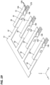
- FIG. 30 is a plan view showing a developed shape of a metal plate material after cutting in a joint terminal according to a fourth embodiment.
- FIG. 31 is a perspective view showing the joint terminal before pressing portions are mounted.
- FIG. 32 is a left side view showing the joint terminal before the pressing portions are mounted.
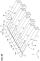
- FIG. 33 is a perspective view showing the joint terminal.
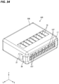
- FIG. 34 is a perspective view showing a joint connector.
- FIG. 35 is a left side view showing the joint connector.
- FIG. 36 is a plan view showing a developed shape of a metal plate material after cutting in a joint terminal according to a fifth embodiment.
- FIG. 37 is a perspective view showing the joint terminal before pressing portions are mounted.
- FIG. 38 is a left side view showing the joint terminal before the pressing portions are mounted.
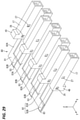
- FIG. 39 is a perspective view showing the joint terminal.
- FIG. 40 is a perspective view showing a joint connector.
- FIG. 41 is a left side view showing the joint connector.
- FIG. 42 is a plan view showing a developed shape of a metal plate material after cutting in a joint terminal according to a sixth embodiment.
- FIG. 43 is a perspective view showing the joint terminal before pressing portions are mounted.
- FIG. 44 is a left side view showing the joint terminal before the pressing portions are mounted.
- FIG. 45 is a perspective view showing the joint terminal.
- FIG. 46 is a perspective view showing a joint connector.
- FIG. 47 is a left side view showing the joint connector.
- a joint connector 10 includes a joint terminal 12 for electrically connecting a plurality of wires 11 , and a housing 30 for accommodating the joint terminal 12 .
- a direction indicated by an arrow Z is referred to as an upward direction
- a direction indicated by an arrow Y is referred to as a forward direction
- a direction indicated by an arrow X is referred to as a leftward direction. Only some of a plurality of identical members may be denoted by a reference sign and the other members may not be denoted by the reference sign.
- the wire 11 is such that the outer peripheral surface of a core 13 is surrounded by an insulation coating 14 made of insulating synthetic resin. An end part of the insulation coating 14 is stripped to expose the core 13 .
- the core 13 according to this embodiment is a so-called single-core wire made of one metal wire. Note that the core 13 may be a stranded wire by stranding a plurality of metal thin wires. An arbitrary metal such as coper, copper alloy, aluminum or aluminum alloy can be appropriately selected as a metal constituting the core 13 according to need.
- the core 13 according to this embodiment is made of copper or copper alloy.
- the joint terminal 12 includes a coupling portion 15 extending in a front-rear direction, a plurality of (four in this embodiment) branch portions 16 extending in a lateral direction from both left and right side edges of the coupling portion 15 , and a plurality of (four in this embodiment) wire connecting portions 19 respectively continuous with the plurality of barrel portions 16 and to be connected to the wires 11 .
- the joint terminal 12 is substantially H-shaped when viewed from above.
- the wire connecting portion 19 includes a tubular portion 20 in the form of a rectangular tube continuous from the barrel portion 16 , an upper connecting piece 18 A (an example of a connecting piece) and a lower connecting piece 18 B (an example of the connecting piece) deformable and extending along the lateral direction from an end part of the tubular portion 20 opposite to the barrel portion 16 , and a pressing portion 17 separate from the tubular portion 20 and the upper and lower connecting pieces 18 A, 18 B and to be mounted on the tubular portion 20 .
- the coupling portion 15 , the barrel portions 16 , the tubular portions 20 and the upper and lower connecting pieces 18 A, 18 B are formed by press-working after a metal plate material is cut into a developed shape as shown in FIG. 7 .
- An arbitrary metal such as coper, copper alloy, aluminum, aluminum alloy or stainless steel can be appropriately selected as a metal constituting the metal plate material according to need.
- the metal constituting the metal plate material is made of copper or copper alloy.
- a plating layer may be formed on the surface of the metal plate material.
- An arbitrary metal such as tin, nickel or silver can be appropriately selected as a metal constituting the plating layer according to need. Tin plating is applied to the metal plate material according to this embodiment.
- the coupling portion 15 is in the form of a relatively short plate extending in the front-rear direction. Plate surfaces of the coupling portion 15 are facing in a vertical direction.
- the coupling portion 15 has a substantially rectangular shape when viewed from above.
- first barrel portions 16 A extending leftward are provided respectively from front and rear end parts of the coupling portion 15 .
- two second barrel portions 16 A extending rightward are provided respectively from the front and rear end parts of the coupling portion 15 .
- Plate surfaces of the first and second barrel portions 16 A, 16 B are facing in the vertical direction.
- the first and second barrel portions 16 A, 16 B have a substantially rectangular shape elongated in the lateral direction when viewed from above.
- the wire connecting portions 19 are respectively continuous with end parts of the first and second barrel portions 16 A, 16 B.
- the wire connecting portions 19 continuous with the first barrel portions 16 A and the wire connecting portions 19 continuous with the second barrel portions 16 B are bilaterally symmetrically disposed, and all the wire connecting portions 19 have the same structure.
- the structure of one wire connecting portion 19 is described and the description of the other wire connecting portions 19 is omitted by denoting the same members by the same reference signs.
- the tubular portion 20 of the wire connecting portion 19 is in the form of a rectangular tube elongated in the lateral direction.
- the upper connecting piece 18 A extending in a direction opposite to the barrel portion 16 along the lateral direction from an end part located on a side opposite to the barrel portion 16 is provided on an upper wall of the tubular portion 20 .
- the lower connecting piece 18 B extending in the direction opposite to the barrel portion 16 along the lateral direction from an end part located on the side opposite to the barrel portion 16 is provided on a lower wall of the tubular portion 20 .
- the upper and lower connecting pieces 18 A, 18 B are formed to have substantially the same length in the front-rear direction.
- the upper connecting piece 18 A is formed to be resiliently deformable in the vertical direction with a boundary part to the tubular portion 20 as a fulcrum.
- the lower surface of the upper connecting piece 18 A serves as an upper contact surface 21 A (an example of a contact surface) configured to contact the core 13 .
- An upper holding protrusion 23 A projecting downward is provided at a position near the boundary part to the tubular portion 20 on the upper contact surface 21 A of the upper connecting piece 18 A.
- the upper contact surface 21 A is formed with a plurality of (three in this embodiment) serrations 22 A extending in the front-rear direction and arranged at intervals in the lateral direction.
- the serrations 22 A are in the form of grooves extending in the front-rear direction (see FIG. 16 ).
- the lower connecting piece 18 B is formed to be resiliently deformable in the vertical direction with a boundary part to the tubular portion 20 as a fulcrum.
- the upper surface of the lower connecting piece 18 B serves as a lower contact surface 21 B (an example of the contact surface) configured to contact the core 13 .
- a lower holding protrusion 23 B projecting upward is provided at a position near a projecting end part of the lower connecting piece 18 B on the lower contact surface 21 B of the lower connecting piece 18 B.
- the lower holding protrusion 23 B and the upper holding protrusion 23 A are provided at positions shifted in the lateral direction.
- the lower contact surface 21 B is formed with a plurality of (three in this embodiment) serrations 22 B extending in the front-rear direction and arranged at intervals in the lateral direction.
- the serrations 22 B are in the form of grooves extending in the front-rear direction (see FIG. 16 ).
- the core 13 and the wire connecting portion 19 are electrically connected (see FIG. 16 ).
- the pressing portion 17 is in the form of a rectangular tube extending in the front-rear direction.
- the pressing portion 17 is formed by a known method such as cutting, casting or press-working according to need.
- An arbitrary metal such as coper, copper alloy, aluminum, aluminum alloy or stainless steel can be appropriately selected as a metal constituting the pressing portion 17 according to need.
- the pressing portion 17 is made of copper or copper alloy.
- a plating layer may be formed on the surface of the pressing portion 17 .
- An arbitrary metal such as tin, nickel or silver can be appropriately selected as a metal constituting the plating layer according to need.
- a cross-section of the inner shape of the pressing portion 17 is equal to or somewhat larger than a cross-section of the outer shape of a region of the wire connecting portion 19 where the tubular portion 20 and the upper and lower connecting pieces 18 A, 18 B are provided. In this way, the pressing portion 17 is externally fittable to the region of the wire connecting portion 19 where the tubular portion 20 and the upper and lower connecting pieces 18 A, 18 B are provided.
- An upper contact portion 25 A projecting downward is provided on the lower surface of an upper wall of the pressing portion 17 .
- a lower contact portion 25 B projecting upward is provided on the upper surface of a lower wall of the pressing portion 17 .
- Partial lock receiving portions 26 are open at positions near a front end part in the front-rear direction in side walls of the pressing portion 17 . Further, full lock receiving portions 27 are open at positions behind the partial lock receiving portions 26 in the side walls of the pressing portion 17 .
- the partial lock receiving portions 26 and the full lock receiving portions 27 are resiliently lockable to locking projections 28 provided on side walls of the tubular portion 20 .
- the pressing portion 17 is held at a partial locking position with respect to the tubular portion 20 with the locking projections 28 of the tubular portion 20 and the partial lock receiving portions 26 of the pressing portion 17 locked.
- the upper and lower contact portions 25 A, 25 B of the pressing portion 17 are disposed at positions shifted in the lateral direction from projecting end edges of the upper and lower connecting pieces 18 A, 18 B, and separated from the upper and lower connecting pieces 18 A, 18 B.
- the upper and lower contact portions 25 A, 25 B of the pressing portion 17 do not respectively press the upper and lower connecting pieces 18 A, 18 B against the core 13 of the wire 11 .
- a state where the pressing portion 17 is held at the partial locking position in this way is referred to as a releasing position where the pressing portion 17 does not press the upper and lower connecting pieces 18 A, 18 B against the wire 11 . Further, in this state, an interval between the upper and lower connecting pieces 18 A, 18 B is set larger than a diameter of the core 13 .
- the pressing portion 17 is held at a full locking position with respect to the tubular portion 20 with the locking projections 28 of the tubular portion 20 and the full lock receiving portions 27 of the pressing portion 17 locked.
- the upper contact portions 25 A of the pressing portion 17 is in contact with the upper connecting piece 18 A from a side (upper side) opposite to the upper contact surface 21 A of the upper connecting piece 18 A.
- the lower contact surface 25 B of the pressing portion 17 is in contact with the lower connecting piece 18 B from a side (lower side) opposite to the lower contact surface 21 B of the lower connecting piece 18 B.
- the upper and lower contact portions 25 A, 25 B respectively press the upper and lower connecting pieces 18 A, 18 B against the core 13 of the wire 11 .
- a state where the pressing portion 17 is held at the full locking position in this way is referred to as a pressing position where the pressing portion 17 presses the upper and lower connecting pieces 18 A, 18 B against the wire 11 .
- the pressing portion 17 is slidable along the lateral direction between the partial locking position and the full locking position described above while being externally fit to the region where the tubular portion 20 and the upper and lower connecting pieces 18 A, 18 B are provided.
- the locking projection 28 provided on the tubular portion 20 doubles as a fully locking portion and a partially locking portion.
- the upper contact portion 25 A is in contact with the upper surface of the upper connecting piece 18 A from above and the lower contact portion 25 B is in contact with the lower surface of the lower connecting piece 18 B from below.
- the upper contact portion 25 A presses the upper connecting piece 18 A from above, whereby the upper connecting piece 18 A is resiliently deformed downward.
- the lower contact portion 25 B presses the lower connecting piece 18 B from below, whereby the lower connecting piece 18 B is resiliently deformed upward.
- the core 13 is disposed in a state extended in the lateral direction (extending direction) in a space between the upper and lower connecting pieces 18 A, 18 B and, with the pressing portion 17 held at the full locking position with respect to the tubular portion 20 , the core 13 is sandwiched in the vertical direction by the resiliently deformed upper and lower connecting pieces 18 A, 18 B.
- the upper connecting piece 18 A contacts the core 13 from above by being pressed downward by the upper contact portion 25 A and the lower connecting piece 18 B contacts the core 13 from below by being pressed upward by the lower contact portion 25 B.
- the upper holding protrusion 23 A of the upper connecting piece 18 A presses the core 13 from above and the lower holding protrusion 23 B of the lower connecting piece 18 B presses the core 13 from below.
- the core 13 is pressed from above by the upper holding protrusion 23 A and pressed from below by the lower holding protrusion 23 B disposed at the position shifted in the front-rear direction from the upper holding protrusion 23 A, thereby being held in a state bent in the vertical direction.
- the core 13 and the joint terminal 12 is electrically connected also by the upper and lower holding protrusions 23 A, 23 B.
- a jig contact portion 46 projecting upward from the upper wall is provided at a position of the pressing portion 17 near one end part in the lateral direction.
- a jig 45 comes into contact with the jig contact portion 46 , and the pressing portion 17 is pushed forward by this jig 45 , thereby being moved forward (see FIG. 15 ).
- the jig 45 is in the form of an elongated plate or rod.
- the jig 45 is made of a known material such as metal or synthetic resin. Note that the above jig 45 is relatively small in size as compared to a mold and a facility for operating this mold. Thus, a cost increase due to the jig 45 is suppressed.
- a pair of guiding portions 47 projecting inwardly of the pressing portion 17 are provided on both left and right side walls at positions of the pressing portion 17 near the other end part in the lateral direction.
- the core 13 slides in contact with the inner surfaces of the guiding portions 47 , whereby the core 13 is guided into the pressing portion 17 .
- the housing 30 of the joint connector 10 includes a cavity 29 for accommodating the joint terminal 12 .
- Holders 31 are respectively mounted on left and right end parts of the housing 30 .
- the housing 30 has a substantially rectangular parallelepiped shape flat in the vertical direction and extending in the lateral direction.
- the housing 30 is formed by injection-molding insulating synthetic resin.
- the housing 30 includes a lower case 50 and an upper case 51 to be assembled with the lower case 50 from above.
- the lower case 50 has a bottom wall and side walls extending upward from both front and rear side edges of the bottom wall.
- Lock receiving portions 53 to be resiliently locked by lock portions 52 to be described later are formed to extend downward at laterally center positions of the side walls of the lower case 50 .
- the bottom wall of the lower case 50 is recessed downward to form a coupling portion accommodating portion 54 , branch portion accommodating portions 55 and wire connecting portion accommodating portions 56 .
- the coupling portion accommodating portion 54 , the branch portion accommodating portions 55 and the wire connecting portion accommodating portions 56 are formed into a shape in conformity with the joint terminal 12 when viewed from above.
- the coupling portion accommodating portion 54 extending in the front-rear direction is provided at a laterally center position of the bottom wall of the lower case 50 .
- the coupling portion 15 is accommodated into this coupling portion accommodating portion 54 from above.
- the branch portion accommodating portions 55 respectively extend in the lateral direction from front and rear end parts of the coupling portion accommodating portion 54 .
- the respective branch portions 16 are respectively accommodated into these branch portion accommodating portions 55 .
- the wire connecting portion accommodating portion 56 into which the wire connecting portion 19 is accommodated is provided to extend in the lateral direction on an end part in the lateral direction of each branch portion accommodating portion 55 .
- a part of the wire connecting portion accommodating portion 56 opposite to the branch portion accommodating portion 55 is open in the lateral direction.
- the upper case 51 has an upper wall 58 and side walls respectively extending downward from both front and rear side edges of the upper wall 58 .
- the lock portions 52 extending downward and having lower end parts bent inward in the front-rear direction are formed at positions near laterally center positions and corresponding to the lock receiving portions 53 of the lower case 50 on the side walls of the upper case 51 .
- the lock portions 52 are in the form of plates resiliently deformable in the front-rear direction. These lock portions 52 resiliently engage the lock receiving portions 53 , whereby the lower case 50 and the upper case 51 are integrally assembled.
- the upper wall 58 of the upper case 51 is recessed upward to form a plurality of (four in this embodiment) wire connecting portion accommodating portions 57 into which the respective wire connecting portions 19 are accommodated.
- the upper wall 58 of the upper case 51 is formed with work holes 59 penetrating through the upper wall 58 at positions corresponding to the respective wire connecting portion accommodating portions 57 .
- the work holes 59 have a rectangular shape elongated in the lateral direction when viewed from above (see FIG. 11 ).
- An opening area of the work hole 59 is set larger than a cross-sectional area of the jig 45 to be described later. In this way, the jig 45 can be inserted into the cavity 29 through the work hole 59 and brought into contact with the jig contact portion of the pressing portion as described later.
- the cavity 29 into which the joint terminal 12 is accommodated is formed between an inner wall of the lower case 50 and an inner wall of the upper case 51 .
- the cavity 29 includes the coupling portion accommodating portion 54 , the branch portion accommodating portions 55 and the wire connecting portion accommodating portions 56 , 57 .
- the cavity 29 formed in the housing 30 is open leftward and rightward respectively at left and right end parts of the housing 30 .
- regions of the upper wall 58 of the upper case 51 corresponding to the branch portion accommodating portions 55 and the coupling portion accommodating portion 54 of the lower case 50 are formed such that intervals in the vertical direction between these regions and the branch portion accommodating portions 55 and the coupling portion accommodating portion 54 are somewhat larger than thicknesses of the branch portions 16 and the coupling portion 15 of the joint terminal 12 .
- the coupling portion 15 and the branch portions 16 respectively accommodated in the branch portion accommodating portions 55 and the coupling portion accommodating portion 54 of the lower case 50 are held in the housing 30 by being sandwiched by the lower case 50 and the upper case 51 .
- partial locking portions 36 projecting outward along the front-rear direction are provided at positions near left and right end parts on front and rear walls of the upper case 51 .
- full locking portions 37 are provided to project outward along the front-rear direction at positions inwardly of the partial locking portions 36 in the lateral direction.
- the holder 31 mounted on the left end part of the housing 30 includes a holding wall 32 (an example of an engaging portion) and gate-shaped lock receiving portions 38 respectively extending rightward from front and rear end edges of the holding wall 32 .
- the holder 31 is formed by injection-molding insulating synthetic resin.
- the lock receiving portion 38 is resiliently locked to each of the partial locking portion 36 and the full locking portion 37 provided on the housing 30 .
- the holder 31 is held at a partial locking position with respect to the housing 30 by locking the partial locking portions 36 of the housing 30 and the lock receiving portions 38 of the holder 31 (see FIG. 12 ). Further, the holder 31 is held at the full locking position with respect to the housing 30 by locking the full locking portions 37 of the housing 30 and the lock receiving portions 38 of the holder 31 (see FIG. 1 ).
- the holding wall 32 is formed to have substantially the same shape as the left side wall of the housing 30 with the lower case 50 and the upper case 51 assembled. With the holder 31 assembled with the housing 30 , the holding wall 32 of the holder 31 covers the left side wall of the housing 30 from the left.
- the holding wall 32 is formed with a plurality of (two in this embodiment) insertion holes 39 arranged side by side in the front-rear direction and penetrating through the holding wall 32 in the lateral direction.
- the insertion holes 39 are formed at positions corresponding to parts of the cavity 29 open in the left side wall of the housing 30 . In this way, the insertion holes 39 communicate with the cavity 29 of the housing 30 .
- An inner diameter of the insertion hole 39 is set equal to or somewhat larger than an external dimension of the insulation coating 14 of the wire 11 . In this way, the wire 11 is inserted into the insertion hole 39 .
- Tapered surfaces 33 tapered toward the right are formed on hole edge parts of the insertion holes 39 in the left side surface of the holding wall 32 .
- the wire 11 is guided into the insertion hole 39 by sliding in contact with the tapered surface 33 .
- the holding wall 32 of the holder 31 is located to the left of the left side surface of the housing 30 .
- the right side surface of the holding wall 32 of the holder 32 is disposed at a position in contact with or somewhat separated leftward from the left side surface of the housing 30 .
- the same members are denoted by the same reference signs and repeated description is omitted.
- the metal plate material is cut into the developed shape shown in FIG. 7 .
- Parts 40 where the tubular portions 20 and the upper and lower connecting pieces 18 A, 18 B are formed are formed side by side in the front-rear direction and symmetrically formed in the front-rear direction. In this way, an interval between the branch portions 16 arranged in the front-rear direction can be made smaller as compared to the case where the parts 40 where the tubular portions 20 and the upper and lower connecting pieces 18 A, 18 B are formed are not symmetrically formed in the front-rear direction.
- the metal plate material formed into the developed shape is press-worked, thereby forming parts of the joint terminal 12 different from the pressing portions 17 as shown in FIGS. 4 to 6 .
- the pressing portions 17 are formed into a predetermined shape (see FIGS. 8 and 9 ).
- the pressing portions 17 are mounted from the left on the tubular portions 20 provided on the tips of the branch portions 16 extending leftward from the coupling portion 15 . Further, the pressing portions 17 are mounted from the right on the tubular portions 20 provided on the tips of the branch portions 16 extending rightward from the coupling portion 15 .
- End edges of the pressing portions 17 come into contact with the locking projections 28 of the tubular portions 20 , whereby the side walls of the pressing portions 17 are expanded and deformed. If the pressing portions 17 are further pushed toward the tubular portions 20 , the side walls of the pressing portions 17 are restored and the partial lock receiving portions 26 of the pressing portions 17 are locked to the locking projections 28 of the tubular portions 20 . In this way, the pressing portions 17 are held at the partial locking position with respect to the tubular portions 20 . In this way, the joint terminal 12 is obtained.
- the lower case 50 By injection-molding synthetic resin, the lower case 50 , the upper case 51 and the holders 31 are formed.
- the joint terminal 12 is accommodated into a lower accommodation recess of the lower case 50 from above.
- the coupling portion 15 of the joint terminal 12 is accommodated into the coupling portion accommodating portion 54 of the lower case 50
- the branch portions 16 of the joint terminal 12 are accommodated into the branch portion accommodating portions 55 of the lower case 50
- the wire connecting portions 19 of the joint terminal 12 are accommodated into the wire connecting portion accommodating portions 56 of the lower case 50 .
- the upper case 51 is brought closer to the lower case 50 from above the lower case 50 .
- lower end parts of the lock portions 52 of the upper case 51 come into contact with the lock receiving portions 53 of the lower case 50 from above. If the upper case 51 is moved further downward, the lock portions 52 ride on the lock receiving portions 53 , whereby the lock portions 52 are expanded and deformed outward in the front-rear direction. If the upper case 51 is moved further downward, the lock portions 52 are restored. In this way, the lock portions 52 come into contact with the lock receiving portions 53 from below, whereby the upper case 51 and the lower case 50 are integrally assembled.
- the holder 31 is mounted from the left on the left end part of the housing 30 , and the holder 31 is mounted from the right on the right end part of the housing 30 .
- Tip parts of the lock receiving portions 38 of the holders 31 come into contact with the partial locking portions 36 of the housing 30 and the lock receiving portions 38 are expanded and deformed. If the holders 31 are further pushed toward the housing 30 , the tip parts of the lock receiving portions 38 are restored and the lock receiving portions 38 of the holders 31 are resiliently locked to the partial locking portions 36 of the housing 30 . In this way, the holders 31 are held at the partial locking position with respect to the housing 30 . In this state, the holding walls 32 of the holders 31 are disposed at positions separated rearward from the rear end edges of the pressing portions 17 (see FIG. 13 ).
- the insulation coating 14 is stripped in an end part of the wire 11 , thereby exposing the core 13 of a predetermined length.
- the core 13 of the wire 11 is inserted into the insertion hole 39 provided in the holding wall 32 of the holder 31 .
- the tip of the core 13 slides in contact with the tapered surface 33 formed on the hole edge part of the insertion hole 39 provided in the holding wall 32 , whereby the core 13 is guided into the insertion hole 39 .
- the tip part of the core 13 projects toward the joint terminal 12 from the insertion hole 39 of the holder 31 and inserted into the pressing portion 17 . At this time, the tip of the core 13 slides in contact with the guiding portions 47 of the pressing portion 17 , thereby being guided into the pressing portion 17 . If the wire 11 is pushed further into the housing 30 , the tip part of the core 13 enters the tubular portion 20 and reaches the space between the upper and lower connecting pieces 18 A, 18 B.
- the core 13 enters the tubular portion 20 .
- the insulation coating 14 of the wire 11 is located in the insertion hole 39 of the holder 31 (see FIG. 14 ).
- the core 13 does not receive large friction forces from the upper and lower connecting pieces 18 A, 18 B when being inserted into the joint connector 10 since the interval between the upper and lower connecting pieces 18 A, 18 B is set larger than the outer diameter of the core 13 .
- an insertion force in inserting the wire 11 into the joint connector 10 can be reduced.
- the jigs 45 are inserted into the work holes 59 of the housing 30 from above and brought into contact with the jig contact portions 46 .
- the pressing portions 17 are relatively moved with respect to the tubular portions 20 by pressing the jig contact portions 46 by the jigs 45 .
- the pressing portions 17 of the wire connecting portions 19 formed to the left of the coupling portion 15 are relatively moved rightward with respect to the tubular portions 20
- the pressing portions 17 of the wire connecting portions 19 formed to the right of the coupling portion 15 are relatively moved leftward with respect to the tubular portions 20 .
- locking between the locking projections 28 of the tubular portions 20 and the partial lock receiving portions 26 of the pressing portions 17 is released and the side walls of the pressing portions 17 ride on the locking projections 28 to be expanded and deformed.
- the pressing portions 17 are further moved, the side walls of the pressing portions 17 are restored and the locking projections 28 of the tubular portions 20 and the full lock receiving portions 27 of the pressing portions 17 are resiliently locked. In this way, the pressing portions 17 are held at the full locking position with respect to the tbsp 20 (see FIG. 15 ).
- the upper contact portion 25 A of the pressing portion 17 comes into contact with the upper connecting piece 18 A of the tubular portion 20 from above to press the upper connecting piece 18 A downward.
- the lower contact portion 25 B of the pressing portion 17 comes into contact with the lower connecting piece 18 B of the tubular portion 20 from below to press the lower connecting piece 18 B upward.
- the core 13 is sandwiched from upper and lower sides by the upper and lower connecting pieces 18 A, 18 B.
- the upper and lower connecting pieces 18 A, 18 B are held in contact with the core 13 , whereby the wire 11 and the joint terminal 12 are electrically connected (see FIG. 16 ).
- the serrations 22 A, 22 B bite into the surface of the core 13 , whereby the electrical connection reliability of the core 13 and the upper and lower connecting pieces 18 A, 18 B is improved.
- the core 13 With the core 13 vertically sandwiched by the upper and lower connecting pieces 18 A, 18 B, the core 13 is sandwiched by the upper holding protrusion 23 A of the upper connecting piece 18 A and the lower holding protrusion 23 B of the lower connecting piece 18 B, thereby being held in the state bent in the vertical direction while extending in the front-rear direction. Since the core 13 can be firmly held in this way, a holding force of the wire 11 and the joint terminal 12 can be enhanced when a pulling force acts on the wire 11 .
- the holders 31 are moved from the partial locking position to the full locking position.
- the holder 31 mounted on the left end part of the housing 30 is moved rightward, and the holder 31 mounted on the right end part of the housing 30 is moved leftward.
- the lock receiving portions 38 of the holders 31 ride on the full locking portions 37 of the housing 30 to be expanded and deformed. If the holders 31 are further pressed, the lock receiving portions 38 of the holders 31 ride over the full locking portions 37 to be restored, and the full locking portions 37 of the housing 30 and the lock receiving portions 38 of the holders 31 are locked. In this way, the holders 31 are held at the full locking position with respect to the housing 30 (see FIGS. 1 and 3 ).
- the holding walls 32 of the holders 31 come into contact with the pressing portions 17 , whereby the pressing portions 17 are retained and held inside the housing 30 .
- the pressing portion 17 may be stopped between the partial locking position and the full locking position in the process of moving the pressing portion 17 to the full locking position.
- a state of electrical connection of the core 13 and the upper and lower connecting pieces 18 A, 18 B is not sufficient. This is because contact pressures of the upper and lower connecting pieces 18 A, 18 B with the core 13 are not sufficient. If an attempt is made to move the holder 31 from the partial locking position to the full locking position in this state, the inner surface of the holding wall 32 of the holder 31 comes into contact with the pressing portion 17 , whereby the holder 31 cannot be moved to the full locking position. In this way, whether or not the pressing portions 17 have been moved to the full locking position can be determined.
- the joint connector 10 is provided with the joint terminal 12 and the housing 30 configured to accommodate the joint terminal 12 , the joint terminal 12 includes the plurality of branch portions 16 , the plurality of wire connecting portions 19 respectively continuous with the plurality of branch portions 16 and to be connected to the wires 11 and the coupling portion 15 electrically connecting the plurality of branch portions 16 by coupling the plurality of branch portions 16 .
- the wire connecting portion 19 includes the upper and lower connecting pieces 18 A, 18 B having the upper and lower contact surfaces 21 A, 21 B configured to contact the wire 11 , and the pressing portion 17 configured to press the upper connecting piece 18 A against the wire 11 by coming into contact with the upper connecting piece 18 A and press the lower connecting piece 18 B against the wire 11 by coming into contact with the lower connecting piece 18 B.
- the wires 11 and the joint terminal 12 can be electrically connected by pressing the upper and lower connecting pieces 18 A, 18 B against the wires 11 by the pressing portions 17 after the wires 11 are disposed on the upper and lower contact surfaces 21 A, 21 B of the wire connecting portions 19 .
- an assembly process of the joint connector 10 can be made more efficient as compared to the case where a step of connecting female terminals, which are members separate from the joint terminal 12 , and the wires 11 is separately performed.
- the parts 40 adjacent in the front-rear direction for forming the tubular portions 20 and the upper and lower connecting pieces 18 A, 18 B are symmetrically shaped in the front-rear direction in the developed shape. In this way, the interval between the branch portions 16 arranged in the front-rear direction can be made narrower.
- the pressing portion 17 moves along the lateral direction between the pressing position where the pressing portion 17 presses the upper and lower connecting pieces 18 A, 18 B against the core 13 of the wire 11 and the releasing position where the pressing portion 17 does not press the upper and lower connecting pieces 18 A, 18 B against the core 13 of the wire 11 .
- the wire 11 and the joint terminal 12 can be electrically connected by a simple operation of moving the pressing portion 17 from the releasing position to the pressing position.
- the pressing portion 17 is provided with the jig contact portion 46 projecting in the vertical direction, and moved from the releasing position to the pressing position by being pressed by the jig 45 with the jig contact portion 46 held in contact with the jig 45 .
- the wire 11 and the joint terminal 12 can be electrically connected by bringing the jig 45 into contact with the jig contact portion 46 and moving the pressing portion 17 from the releasing position to the pressing position.
- the jig contact portion 46 is provided on one vertical side of the pressing portion 17 .
- an operation of moving the pressing portion 17 in the lateral direction only has to be performed from one side in the vertical direction, wherefore the efficiency of an assembly operation of the joint connector 10 can be improved.
- the holders 31 are mounted on the housing 30 , and include the holding walls 32 configured to restrict movements of the pressing portions 17 at the pressing position to the releasing position by engaging the pressing portions 17 while being mounted on the housing 30 .
- the pressing portions 17 can be retained and held in the housing 30 by the engagement of the holding walls 32 of the holders 31 with the pressing portions 17 .
- the plurality of wire connecting portions 19 are disposed on opposite ends in a longitudinal direction (lateral direction) of the branch portions 16 .
- the wires 11 routed toward the joint connector 10 from different directions along the lateral direction can be electrically connected.
- a joint terminal 60 includes a coupling portion 61 elongated in a front-rear direction.
- the coupling portion 61 is in the form of a plate having a rectangular shape when viewed from above.
- a plurality of (four in this embodiment) branch portions 61 extending leftward are disposed side by side at intervals in the front-rear direction on a left side edge of the coupling portion 61 .
- a wire connecting portion 19 is formed on the tip of each branch portion 62 .
- the joint terminal 60 is formed by press-working after a metal plate material is cut into a developed shape shown in FIG. 21 .
- parts 76 where tubular portions 20 and upper and lower connecting pieces 18 A, 18 B are formed are formed to have the same shape when viewed from above.
- the parts 76 adjacent in the front-rear direction where the tubular portions 20 and the upper and lower connecting pieces 18 A, 18 B are formed are arranged without any clearance therebetween. In this way, a yield in manufacturing the joint terminal 60 from the metal plate material can be improved. Further, intervals in the front-rear direction between a plurality of the wire connecting portions 19 formed after press-working can be made narrower.
- the housing 63 is formed by injection-molding insulating synthetic resin.
- the housing 63 has a substantially rectangular shape as a whole.
- the housing 63 includes a cavity 67 for accommodating the joint terminal 60 .
- the cavity 67 includes a coupling portion accommodating portion 64 into which the coupling portion 61 of the joint terminal 60 is press-fit, branch portion accommodating portions 65 into which the branch portions 62 of the joint terminal 60 are accommodated, and wire connecting portion accommodating portions 66 into which the wire connecting portions 19 of the joint terminal 60 are accommodated.
- left end parts of the wire connecting portion accommodating portions 66 are open leftward.
- a slit 68 into which the coupling portion 61 of the joint terminal 60 is inserted is formed to extend in the front-rear direction in a left side wall of the housing 63 .
- a length in the front-rear direction of the slit 68 is equal to or somewhat longer than that of the coupling portion 61 of the joint terminal 60 .
- a vertical height of the slit 68 is set equal to or somewhat larger than that of the coupling portion 61 of the joint terminal 60 .
- the coupling portion accommodating portion 64 is formed to extend in the front-rear direction.
- a vertical height of the coupling portion accommodating portion 64 is set equal to or somewhat larger than a vertical thickness of the coupling portion 61 of the joint terminal 60 .
- ribs 74 are formed to project inwardly of the branch portion accommodating portions 65 on upper and lower walls of the branch portion accommodating portions 65 .
- the joint terminal 60 is retained and held in the housing 63 by press-fitting the branch portions 62 of the joint terminal 60 between the ribs 74 in the branch portion accommodating portions 65 .
- An upper wall 69 of the housing 63 is formed with work holes 70 penetrating through the upper wall 69 at positions corresponding to the wire connecting portion accommodating portions 66 .
- the work holes 70 have a rectangular shape elongated in a lateral direction when viewed from above.
- the wire connecting portion accommodating portions 66 are allowed to communicate with the outside of the housing 63 by these work holes 70 .
- partial locking portions 36 projecting outward in the front-rear direction are provided at positions near right end parts on side walls of the housing 63 .
- full locking portions 37 are provided to project outward at positions to the right of the partial locking portions 36 .
- a holder 71 includes a holding wall 72 elongated in the front-rear direction. Gate-shaped lock receiving portions 38 extending rightward are respectively provided on front and rear end edges of the holding wall 72 .
- the holder 71 is formed by injection-molding insulating synthetic resin.
- the holding wall 72 is formed to have substantially the same size as the left side wall of the housing 63 . With the housing 71 assembled with the housing 63 , the holding wall 72 (an example of the engaging portion) of the holder 71 covers the left side wall of the housing 63 from the left.
- the holding wall 72 is formed with a plurality of (fourth in this embodiment) insertion holes 73 arranged in the front-rear direction and penetrating through the holding wall 72 in the lateral direction.
- the insertion holes 73 are formed at positions corresponding to parts of the cavity 67 open in the left side wall of the housing 63 . In this way, the insertion holes 73 communicate with the cavity 67 of the housing 63 .
- An inner diameter of the insertion hole 73 is set equal to or somewhat larger than an outer diameter of an insulation coating 14 of a wire 11 . In this way, the wire 11 is inserted into the insertion hole 73 .
- Tapered surfaces tapered toward the right are formed on hole edge parts of the insertion holes 73 in the left side surface of the holding wall 72 .
- the wires 11 are guided into the insertion holes 73 by sliding in contact with these tapered surfaces.
- the joint terminal 60 is formed into a developed shape shown in FIG. 21 by cutting the metal plate material.
- the parts 76 where the tubular portions 20 and the upper and lower connecting pieces 18 A, 18 B are formed are formed to the left of the coupling portion 61 and side by side in the front-rear direction. Further, the parts 76 where the tubular portions 20 and the upper and lower connecting pieces 18 A, 18 B are form are formed to have the same shape when viewed from above, and formed side by side without any clearance in the front-rear direction. In this way, the intervals between the branch portions 62 arranged in the front-rear direction can be made smaller.
- parts of the joint terminal 60 different from the pressing portions 17 are formed as shown in FIGS. 19 and 20 by press-working the metal plate material formed into the developed shape. Subsequently, the pressing portions 17 are formed into a predetermined shape.
- the pressing portions 17 are mounted from the left on the tubular portions 20 provided on the tips of the branch portions 62 extending leftward from the coupling portion 61 .
- the housing 63 is formed by injection-molding synthetic resin.
- the joint terminal 60 is disposed to the left of the housing 63 with the coupling portion 61 facing rightward and the wire connecting portions 19 facing leftward.
- the coupling portion 61 of the joint terminal 60 is inserted into the slit 68 formed in the left side wall of the housing 63 from the left.
- the coupling portion 61 and the branch portions 62 are inserted into the coupling portion accommodating portion 64 and the branch portion accommodating portions 65 of the housing 63 from the left.
- the branch portions 62 are sandwiched between the ribs 74 formed in the branch portion accommodating portions 65 , whereby the joint terminal 60 is retained and held in the housing 63 .
- the holder 71 is mounted from the left on the left end part of the housing 63 and the lock receiving portions 38 of the holder 71 are resiliently locked to the partial locking portions 36 of the housing 63 to hold the holder 71 at a partial locking position with respect to the housing 63 .
- the holding wall 72 of the holder 71 is disposed at a position separated rearward from rear end edges of the pressing portions 17 .
- the cores 13 exposed from the insulation coatings 14 of the wires 11 are inserted into the insertion holes 73 provided in the holding wall 72 of the holder 71 .
- the cores 13 are disposed inside the tubular portions 20 and the insulation coatings 14 of the wires 11 are disposed in the insertion holes 73 of the holder 71 .
- a jig 45 is inserted into the work hole 70 of the housing 63 from above and brought into contact with a jig contact portion 46 .
- the jig contact portion 46 is pressed by the jig 45 to move the pressing portion 17 relatively rightward with respect to the tubular portion 20 .
- locking projections 28 of the tubular portion 20 and full locking portions 27 of the pressing portion 17 are resiliently locked, whereby the pressing portion 17 is held at a full locking position with respect to the tubular portion 20 .
- an upper contact portion 25 A of the pressing portion 17 comes into contact with the upper connecting piece 18 A of the tubular portion 20 from above to press the upper connecting piece 18 A downward.
- a lower contact portion 25 B of the pressing portion 17 comes into contact with the lower connecting piece 18 B of the tubular portion 20 from below to press the lower connecting piece 18 B upward.
- the core 13 is sandwiched from upper and lower sides by the upper and lower connecting pieces 18 A, 18 B.
- the core 13 is held in contact with the upper and lower connecting pieces 18 A, 18 B, whereby the wire 11 and the joint terminal 12 are electrically connected.
- the holder 71 is moved from the partial locking position to a full locking position. Then, the lock receiving portions 38 of the holder 71 ride over the full locking portions 37 to be restored and the full locking portions 37 of the housing 63 and the lock receiving portions 38 of the holder 71 are locked. In this way, the holder 71 is held at the full locking position with respect to the housing 63 (see FIG. 22 ). As a result, the holding wall 72 of the holder 71 is engaged with the pressing portions 17 to retain and hold the pressing portions 17 inside the housing 63 . In this way, the joint connector 75 is completed (see FIG. 23 ).
- the structures adjacent in the front-rear direction for forming the tubular portions 20 and the upper and lower connecting pieces 18 A, 18 B are formed to have the same shape when viewed from above in the developed shape. In this way, the intervals between the branch portions 62 arranged in the front-rear direction can be suppressed from becoming excessively wide.
- a joint terminal 80 includes a plurality of branch portions 82 .
- the plurality of branch portions 82 include first branch portions 82 A and second branch portions 82 B to be described later.
- the joint terminal 80 is press-worked after being cut into a developed shape as shown in FIG. 24 .
- a plurality of (four in this embodiment) the first branch portions 82 A are formed to extend leftward on a left side edge of a coupling portion 81 extending in a front-rear direction.
- the respective first branch portions 82 A are arranged at equal intervals in the front-rear direction.
- a plurality of (four in this embodiment) the second branch portions 82 B are formed to extend rightward on a right side edge of the coupling portion 81 .
- the respective second branch portions 82 B are arranged at equal intervals in the front-rear direction.
- the first branch portions 82 A disposed to the left of the coupling portion 81 and the second branch portions 82 B to the right of the coupling portion 81 are disposed at positions shifted in the front-rear direction.
- the second branch portions 82 B disposed to the right of the coupling portion 81 are arranged by being shifted forward by half the interval in the front-rear direction of the first branch portions 82 A disposed to the left of the coupling portion 81 .
- a lateral length of the second branch portions 82 B disposed to the right of the coupling portion 81 is set longer than that of the first branch portions 82 A disposed to the left of the coupling portion 81 by a lateral width of the coupling portion 81 .
- branch portion folded portions 83 extending in the front-rear direction are formed in boundary parts between the right side edge of the coupling portion 81 and the first branch portions 82 B disposed to the right of the coupling portion 81 .
- the second branch portions 82 B formed on the right side edge of the coupling portion 81 are folded leftward and disposed to extend leftward of the coupling portion 81 .
- the second branch portions 82 B are folded to extend in the same direction as an extending direction (leftward direction) of the first branch portions 82 A.
- the folded second branch portions 82 B partially overlap on the upper surface of the coupling portion 81 .
- the lateral length of the second branch portions 82 B formed on the right side edge of the coupling portion 81 is set longer than that of the first branch portions 82 A formed on the left side edge of the coupling portion 81 by the lateral width of the coupling portion 81 .
- the positions of left end parts of the wire connecting portions 19 formed on the first branch portions 82 A extending from the left side edge of the coupling portion 81 and those of left end parts of the wire connecting portions 19 formed on the second branch portions 82 B folded from the right side edge of the coupling portion in the branch portion folded portions 83 are substantially aligned in the front-rear direction when viewed from above.
- the wire connecting portions 19 formed on the first branch portions 82 A extending from the left side edge of the coupling portion 81 are disposed above the coupling portion 81 and constitute an upper wire connecting portion row 84 A (an example of a wire connecting portion row) arranged in the front-rear direction.
- the wire connecting portions 19 formed on the second branch portions 82 B folded from the right side edge of the coupling portion 81 in the branch portion folded portions 83 are disposed below the coupling portion 81 and constitute a lower wire connecting portion row 84 B (an example of the wire connecting portion row) arranged in the front-rear direction.
- the upper and lower wire connecting portion rows 84 A, 84 B are arranged in the vertical direction.
- wire connecting portions 19 formed on the first branch portions 82 A extending from the left side edge of the coupling portion 81 and the wire connecting portions 19 formed on the second branch portions 82 B folded from the right side edge of the coupling portion 81 in the branch portion folded portions 83 are disposed in opposite orientations in the vertical direction.
- the terms of members and the positions thereof shown in figures may be opposite.
- the upper connecting pieces 18 A are shown to be located on a lower side for the above reason.
- a plurality of (four in this embodiment) wire connecting portion accommodating portions 87 A into which the wire connecting portions 19 formed on the first branch portions 82 A extending from the left side edge of the coupling portion 81 are accommodated are provided to be open leftward at positions above a vertical center position in a left side wall of the housing 85 .
- a plurality of (four in this embodiment) wire connecting portion accommodating portions 87 B into which the wire connecting portions 19 formed on the second branch portions 82 B folded from the right side edge of the coupling portion 81 in the branch portion folded portions 83 are accommodated are provided to be open leftward at positions below the vertical center position in the left side wall of the housing 85 .
- the wire connecting portion accommodating portions 87 A provided in an upper half of the left side wall of the housing 85 and the wire connecting portion accommodating portions 87 B provided in a lower half of the side wall of the housing 85 are disposed at positions shifted in the front-rear direction.
- a holder is mounted on a left end part of the housing 85 .
- Insertion holes into which wires 11 are inserted are formed to penetrate through a holding wall of the holder in the lateral direction at positions corresponding to the wire connecting portion accommodating portions 87 A, 87 B provided in the left side wall of the housing 85 .
- the joint terminal 80 is formed into a developed shape shown in FIG. 24 by cutting a metal plate material. Subsequently, the second branch portions 82 B formed on the right side edge of the coupling portion 81 are folded in the branch portion folded portions 83 and press-worked and pressing portions 17 are mounted, whereby the joint terminal 80 shown in FIG. 29 is formed.
- the plurality of branch portions 82 include the first branch portions 82 A branched on the left side of the coupling portion 81 and the second branch portions 82 B branched on the right side of the coupling portion 81 , and the second branch portions 82 B are folded to extend in the same direction (leftward direction) as the extending direction of the first branch portions 82 A.
- the second branch portions 82 B are folded in the branch portion folded portions 83 , whereby the wire connecting portions 19 continuous with the second branch portions 82 B can be disposed between adjacent ones of the plurality of wire connecting portions 19 continuous with the first branch portions 82 A arranged in the front-rear direction.
- the joint connector 90 can be made narrower in the front-rear direction.
- the joint terminal 80 includes two wire connecting portion rows 84 A, 84 B in each of which a plurality of wire connecting portions 19 are arranged along the front-rear direction, and the plurality of wire connecting portion rows 84 A, 84 B are disposed side by side in the vertical direction.
- the joint terminal 80 can be reduced in size in the front-rear direction.
- the joint connector 90 can be reduced in size in the front-rear direction.
- the upper and lower wire connecting portion rows 84 A, 84 B are disposed at the positions shifted in the front-rear direction. In this way, intervals between the wire connecting portions 19 adjacent in the front-rear direction can be set to be relatively wide in the upper wire connecting portion row 84 A. In this way, walls separating the wire connecting portion accommodating portions 87 A adjacent in the front-rear direction can be formed to be thick for the wire connecting portion accommodating portions 87 A into which the wire connecting portions 19 constituting the upper wire connecting portion row are accommodated. Thus, the strength of the housing 85 can be improved.
- walls separating the wire connecting portion accommodating portions 87 B adjacent in the front-rear direction can be formed to be thick for the wire connecting portion accommodating portions 87 B into which the wire connecting portions 19 constituting the lower wire connecting portion row are accommodated.
- the strength of the housing 85 can be improved.
- a joint terminal 100 according to this embodiment is press-worked into a shape shown in FIGS. 31 and 32 after being cut into a developed shape as shown in FIG. 30 .
- the joint terminal 100 after press-working includes a plurality of branch portions 102 .
- the plurality of branch portions 102 include first branch portions 102 A and second branch portions 102 B to be described later.
- both wire connecting portions 19 formed on a plurality of (four in this embodiment) the first branch portions 102 A extending from a left side edge of a coupling portion 101 and wire connecting portions 19 formed on a plurality of (four in this embodiment) the second branch portions 102 B folded from a right side edge of the coupling portion 101 in branch portion folded portions 103 are disposed above the coupling portion 101 and arranged in a front-rear direction.
- a plurality of (eight in this embodiment) wire connecting portion accommodating portions 107 open leftward are provided in a left side wall of the housing 106 .
- Lower end parts of the respective wire connecting portion accommodating portions 107 communicate in the front-rear direction.
- a plurality of (eight in this embodiment) wire connecting portions 19 are disposed above the coupling portion 101 in a vertical direction and formed side by side in the front-rear direction. Since the joint terminal 100 can be reduced in size in the vertical direction in this way, a joint connector 105 including the joint terminal 100 can be reduced in size in the vertical direction.
- a joint terminal 111 according to this embodiment is press-worked into a shape shown in FIGS. 37 and 38 after being cut into a developed shape as shown in FIG. 36 .
- a plurality of (eight in this embodiment) branch portions 115 A, 115 B are formed to extend leftward on a left side edge of a coupling portion 112 extending in a front-rear direction.
- the respective branch portions 115 A, 115 B are arranged at equal intervals in the front-rear direction.
- a coupling portion folded portion 113 extending in a lateral direction is formed near a center position in the front-rear direction of the coupling portion 112 .
- the coupling portion 112 is provided with a first coupling portion 112 A and a second coupling portion 112 B overlapped on the upper surface of the first coupling portion 112 A by the coupling portion folded portion 113 .
- a plurality of (four in this embodiment) the first branch portions 115 A formed on a left side edge of the first coupling portion 112 A and a plurality of (four in this embodiment) the second branch portions 115 B formed on a left side edge of the second coupling portion 112 B are disposed side by side at intervals in the front-rear direction.
- the branch portions 115 B formed on the second coupling portion 112 B are bent into a crank shape in boundary parts between the second coupling portion 112 B and the branch portions 115 B, thereby being disposed substantially at the same height positions in the vertical direction as the branch portions 115 A formed on the first coupling portion 112 A.
- the coupling portion 112 includes the coupling portion folded portion 113 folded in a longitudinal direction (front-rear direction) of the coupling portion 112 and the first and second coupling portions 112 A, 112 B delimited by the coupling portion folded portion 113 , and is so folded that the first and second coupling portions 112 A, 112 B overlap.
- the plurality of wire connecting portions 19 provided on the second coupling portion 112 B can be respectively disposed between adjacent ones of the plurality of wire connecting portions 19 provided on the first coupling portion 112 A by folding the coupling portion 112 at the coupling portion folded portion 113 . Since the intervals between the plurality of wire connecting portions 19 arranged in the front-rear direction can be narrowed in this way as shown in FIGS. 40 and 41 , the joint connector 110 can be made narrower in a first direction.
- first and second coupling portions 112 A, 112 B vertically overlap in this embodiment, it is suppressed that an excessive force is applied to the joint terminal 111 by pressing a part where the first and second coupling portions 112 A, 112 B vertically overlap when the joint terminal 111 is press-fit into a housing 114 . In this way, the deformation of the joint terminal 111 in a press-fitting process into the housing 114 can be suppressed.
- a joint terminal 121 according to this embodiment is press-worked into a shape shown in FIGS. 43 and 44 after being cut into a developed shape as shown in FIG. 42 .
- a plurality of (eight in this embodiment) branch portions 123 A, 123 B are formed to extend leftward on a left side edge of a coupling portion 122 extending in a front-rear direction.
- the respective branch portions 123 A, 123 B are arranged at equal intervals in the front-rear direction.
- Parts 125 A which are provided on the tips of the branch portions 123 A, 123 B formed in a front half of the coupling portion 122 and where tubular portions 20 and upper and lower connecting pieces 18 A, 18 B are formed, and parts 125 B which are provided on the tips of the branch portions 123 A, 123 B formed in a rear half of the coupling portion 122 and where tubular portions 20 and upper and lower connecting pieces 18 A, 18 B are formed are formed symmetrically in the front-rear direction.
- a coupling portion folded portion 124 extending along a lateral direction is formed near a center position in the front-rear direction of the coupling portion 122 .
- the coupling portion 122 is provided with a first coupling portion 122 A and a second coupling portion 122 B overlapped on the upper surface of the first coupling portion 122 A by the coupling portion folded portion 124 .
- a plurality of (four in this embodiment) branch portions 123 A formed on a left side edge of the first coupling portion 122 A and a plurality of (fourth in this embodiment) second branch portions 123 B formed on a left side edge of the second coupling portion 122 B are disposed side by side at intervals in the front-rear direction.
- the branch portions 123 B formed on the second coupling portion 122 B are bent downward into a crank shape in boundary parts between the second coupling portion 122 B and the branch portions 123 B, thereby being disposed substantially at the same height positions in a vertical direction as the branch portions 123 A formed on the first coupling portion 122 A.
- a plurality of (eight in this embodiment) wire connecting portion accommodating portions 127 open leftward are provided in a left side wall of the housing 126 .
- Lower end parts of the respective wire connecting portion accommodating portions 127 communicate in the front-rear direction.
- the wire 11 may be a stranded wire formed by stranding a plurality of metal thin wires. Further, the wire 11 may be a so-called bare wire in which the core 13 is exposed without including the insulation coating 14 .
- the pressing portion 17 is configured to slide along the lateral direction (an example of a second direction) in the above embodiments, there is no limitation to this and the pressing portion 17 may be configured to slide along the vertical direction (an example of a third direction).
- the joint terminal may include an arbitrary number of wire connecting portions.
- one tubular portion 20 includes the upper connecting piece 18 A and the lower connecting piece 18 B, there is no limitation to this.
- One tubular portion 20 may be provided with one connecting piece or may be provided with three or more connecting pieces.
- the pressing portion 17 is made of metal, there is no limitation to this and the pressing portion 17 can be made of an arbitrary material such as synthetic resin or ceramic.
- the upper and lower connecting pieces 18 A, 18 B are configured to be resiliently deformed, the upper and lower connecting pieces 18 A, 18 B may be configured to be plastically deformed.
- Two or more joint terminals may be disposed side by side at intervals in the vertical direction in the housing.
Landscapes
- Connector Housings Or Holding Contact Members (AREA)
- Details Of Connecting Devices For Male And Female Coupling (AREA)
- Connections Effected By Soldering, Adhesion, Or Permanent Deformation (AREA)
Abstract
Description
-
- 10, 75, 90, 105, 110, 120: joint connector
- 11: wire
- 12, 60, 80, 100, 111, 12: joint terminal
- 13: core
- 14: insulation coating
- 15, 61, 81, 101, 112, 122: coupling portion
- 16, 62, 82, 102, 115A, 115B, 123, 123A, 123B: branch portion
- 17: pressing portion
- 18A: upper connecting piece (example of connecting piece)
- 18B: lower connecting piece (example of connecting piece)
- 19: wire connecting portion
- 20: tubular portion
- 21A: upper contact surface (example of contact surface)
- 21B: lower contact surface (example of contact surface)
- 22A, 22B: serration
- 23A: upper holding protrusion
- 23B: lower holding protrusion
- 25A: upper contact portion
- 25B: lower contact portion
- 26: partial lock receiving portion
- 27: full lock receiving portion
- 28: locking projection
- 29, 67: cavity
- 30, 63, 85, 106, 114, 126: housing
- 31, 71: holder
- 32, 72: holding wall (example of engaging portion)
- 33: tapered surface
- 36: partial locking portion
- 37: full locking portion
- 38: lock receiving portion
- 39, 73: insertion hole
- 40, 76, 125A, 125B: part where upper and lower connecting pieces are formed
- 45: jig
- 46: jig contact portion
- 47: guiding portion
- 50: lower case
- 51: upper case
- 52: lock portion
- 53: lock receiving portion
- 54: coupling portion accommodating portion
- 55: branch portion accommodating portion
- 56, 57, 66, 107, 127: wire connecting portion accommodating portion
- 58, 69: upper wall
- 59, 70: work hole
- 64: coupling portion accommodating portion
- 65: branch portion accommodating portion
- 68: slit
- 74: rib
- 82A, 102A: first branch portion
- 82B, 102B: second branch portion
- 83, 103: branch portion folded portion
- 84A: upper wire connecting portion row (example of wire connecting portion row)
- 84B: lower wire connecting portion row (example of wire connecting portion row)
- 103: branch portion folded portion
- 112A, 122A: first coupling portion
- 112B, 122B: second coupling portion
- 113, 124: coupling portion folded portion
Claims (7)
Applications Claiming Priority (4)
| Application Number | Priority Date | Filing Date | Title |
|---|---|---|---|
| JPJP2018-107612 | 2018-06-05 | ||
| JP2018-107612 | 2018-06-05 | ||
| JP2018107612 | 2018-06-05 | ||
| PCT/JP2019/021809 WO2019235389A1 (en) | 2018-06-05 | 2019-05-31 | Joint connector |
Publications (2)
| Publication Number | Publication Date |
|---|---|
| US20210234321A1 US20210234321A1 (en) | 2021-07-29 |
| US11228152B2 true US11228152B2 (en) | 2022-01-18 |
Family
ID=68770428
Family Applications (1)
| Application Number | Title | Priority Date | Filing Date |
|---|---|---|---|
| US17/058,024 Expired - Fee Related US11228152B2 (en) | 2018-06-05 | 2019-05-31 | Joint connector |
Country Status (4)
| Country | Link |
|---|---|
| US (1) | US11228152B2 (en) |
| JP (1) | JP6923082B2 (en) |
| CN (1) | CN112335139B (en) |
| WO (1) | WO2019235389A1 (en) |
Cited By (8)
| Publication number | Priority date | Publication date | Assignee | Title |
|---|---|---|---|---|
| US20220077620A1 (en) * | 2020-09-07 | 2022-03-10 | Hyundai Motor Company | Joint Connecter |
| US20220224024A1 (en) * | 2019-05-08 | 2022-07-14 | Autonetworks Technologies, Ltd. | Terminal and wire with terminal |
| US20220239019A1 (en) * | 2019-06-12 | 2022-07-28 | Autonetworks Technologies, Ltd. | Terminal and terminal wire assembly |
| US20220367085A1 (en) * | 2019-11-11 | 2022-11-17 | Sumitomo Wiring Systems, Ltd. | Wire with terminal |
| US20220368056A1 (en) * | 2019-10-24 | 2022-11-17 | Autonetworks Technologies, Ltd. | Joint connector |
| US20220376408A1 (en) * | 2021-05-20 | 2022-11-24 | Yazaki Corporation | Joint connector |
| US11545763B2 (en) * | 2020-02-10 | 2023-01-03 | KYOCERA AVX Components Corporation | Wire-to-wire connector with splice contact portion |
| US20230198172A1 (en) * | 2020-05-29 | 2023-06-22 | Autonetworks Technologies, Ltd. | Terminal and wire with terminal |
Families Citing this family (6)
| Publication number | Priority date | Publication date | Assignee | Title |
|---|---|---|---|---|
| JP7088110B2 (en) | 2019-03-28 | 2022-06-21 | 株式会社オートネットワーク技術研究所 | Joint connector |
| JP7088109B2 (en) * | 2019-03-28 | 2022-06-21 | 株式会社オートネットワーク技術研究所 | Joint connector |
| KR102510449B1 (en) * | 2020-10-29 | 2023-03-16 | 주식회사 유라코퍼레이션 | Interlock Joint Assembly And Junction Block |
| CN115332830B (en) * | 2022-09-06 | 2025-12-12 | 广东省安富电器有限公司 | A splitter connector and its manufacturing process |
| JP2024176635A (en) * | 2023-06-09 | 2024-12-19 | 株式会社オートネットワーク技術研究所 | connector |
| USD1102389S1 (en) * | 2023-10-26 | 2025-11-18 | Hakusan Inc. | Optical connector |
Citations (9)
| Publication number | Priority date | Publication date | Assignee | Title |
|---|---|---|---|---|
| US20020025731A1 (en) * | 2000-08-31 | 2002-02-28 | Yazaki Corporation | Terminal cover |
| JP2002165323A (en) | 2000-11-24 | 2002-06-07 | Hitachi Cable Ltd | Power cable conductor connection parts |
| US6551119B1 (en) * | 1999-03-01 | 2003-04-22 | Yazaki Corporation | Splice absorbing structure |
| JP2006179368A (en) | 2004-12-24 | 2006-07-06 | Kawamura Electric Inc | Screwless terminal |
| US7354318B2 (en) * | 2002-09-19 | 2008-04-08 | The Furukawa Electric Co., Ltd. | Joint connector |
| CN102377030A (en) | 2010-08-20 | 2012-03-14 | 上海市高桥电缆厂有限公司 | Aluminum pipe joint connector structure |
| JP2014002994A (en) | 2012-06-15 | 2014-01-09 | Masanori Kimoto | Coupler for power cable |
| JP2015219955A (en) | 2014-05-14 | 2015-12-07 | 住友電装株式会社 | Joint connector |
| JP2016225248A (en) | 2015-06-03 | 2016-12-28 | 株式会社木村電気工業 | Wire connection device |
Family Cites Families (6)
| Publication number | Priority date | Publication date | Assignee | Title |
|---|---|---|---|---|
| JPH0523422U (en) * | 1991-09-04 | 1993-03-26 | 日本電気株式会社 | Pressure contact type cable connector |
| JP2004356064A (en) * | 2003-05-30 | 2004-12-16 | Yazaki Corp | Assembling method of wire harness |
| JP4080400B2 (en) * | 2003-09-02 | 2008-04-23 | 日本圧着端子製造株式会社 | Terminal metal chain and its windings |
| US7086897B2 (en) * | 2004-11-18 | 2006-08-08 | John Mezzalingua Associates, Inc. | Compression connector and method of use |
| JP5579341B1 (en) * | 2013-02-22 | 2014-08-27 | 古河電気工業株式会社 | Terminal connection band, crimp terminal manufacturing method, wire crimping device, and wire crimping method |
| CN105305124B (en) * | 2015-10-29 | 2018-07-13 | 广州番禺电缆集团有限公司 | A kind of electric wire switching device monomer and the integral type electric wire switching device being made of it |
-
2019
- 2019-05-31 WO PCT/JP2019/021809 patent/WO2019235389A1/en not_active Ceased
- 2019-05-31 US US17/058,024 patent/US11228152B2/en not_active Expired - Fee Related
- 2019-05-31 JP JP2020523080A patent/JP6923082B2/en not_active Expired - Fee Related
- 2019-05-31 CN CN201980037132.2A patent/CN112335139B/en not_active Expired - Fee Related
Patent Citations (9)
| Publication number | Priority date | Publication date | Assignee | Title |
|---|---|---|---|---|
| US6551119B1 (en) * | 1999-03-01 | 2003-04-22 | Yazaki Corporation | Splice absorbing structure |
| US20020025731A1 (en) * | 2000-08-31 | 2002-02-28 | Yazaki Corporation | Terminal cover |
| JP2002165323A (en) | 2000-11-24 | 2002-06-07 | Hitachi Cable Ltd | Power cable conductor connection parts |
| US7354318B2 (en) * | 2002-09-19 | 2008-04-08 | The Furukawa Electric Co., Ltd. | Joint connector |
| JP2006179368A (en) | 2004-12-24 | 2006-07-06 | Kawamura Electric Inc | Screwless terminal |
| CN102377030A (en) | 2010-08-20 | 2012-03-14 | 上海市高桥电缆厂有限公司 | Aluminum pipe joint connector structure |
| JP2014002994A (en) | 2012-06-15 | 2014-01-09 | Masanori Kimoto | Coupler for power cable |
| JP2015219955A (en) | 2014-05-14 | 2015-12-07 | 住友電装株式会社 | Joint connector |
| JP2016225248A (en) | 2015-06-03 | 2016-12-28 | 株式会社木村電気工業 | Wire connection device |
Non-Patent Citations (1)
| Title |
|---|
| International Search Report dated Jul. 16, 2019 for WO 2019/235389 A1 (4 pages). |
Cited By (15)
| Publication number | Priority date | Publication date | Assignee | Title |
|---|---|---|---|---|
| US11764493B2 (en) * | 2019-05-08 | 2023-09-19 | Autonetworks Technologies, Ltd. | Terminal and wire with terminal |
| US20220224024A1 (en) * | 2019-05-08 | 2022-07-14 | Autonetworks Technologies, Ltd. | Terminal and wire with terminal |
| US20220239019A1 (en) * | 2019-06-12 | 2022-07-28 | Autonetworks Technologies, Ltd. | Terminal and terminal wire assembly |
| US11637386B2 (en) * | 2019-06-12 | 2023-04-25 | Autonetworks Technologies, Ltd. | Terminal and terminal wire assembly |
| US20220368056A1 (en) * | 2019-10-24 | 2022-11-17 | Autonetworks Technologies, Ltd. | Joint connector |
| US12237607B2 (en) * | 2019-10-24 | 2025-02-25 | Autonetworks Technologies, Ltd. | Joint connector including branch portions and coupling portion |
| US20220367085A1 (en) * | 2019-11-11 | 2022-11-17 | Sumitomo Wiring Systems, Ltd. | Wire with terminal |
| US12142398B2 (en) * | 2019-11-11 | 2024-11-12 | Sumitomo Wiring Systems, Ltd. | Wire with a terminal having reinforce material |
| US11545763B2 (en) * | 2020-02-10 | 2023-01-03 | KYOCERA AVX Components Corporation | Wire-to-wire connector with splice contact portion |
| US20230198172A1 (en) * | 2020-05-29 | 2023-06-22 | Autonetworks Technologies, Ltd. | Terminal and wire with terminal |
| US12266897B2 (en) * | 2020-05-29 | 2025-04-01 | Autonetworks Technologies, Ltd. | Terminal and wire with terminal |
| US11749930B2 (en) * | 2020-09-07 | 2023-09-05 | Hyundai Motor Company | Joint connecter having an isolation terminal and connection terminal |
| US20220077620A1 (en) * | 2020-09-07 | 2022-03-10 | Hyundai Motor Company | Joint Connecter |
| US12046861B2 (en) * | 2021-05-20 | 2024-07-23 | Yazaki Corporation | Joint connector |
| US20220376408A1 (en) * | 2021-05-20 | 2022-11-24 | Yazaki Corporation | Joint connector |
Also Published As
| Publication number | Publication date |
|---|---|
| JP6923082B2 (en) | 2021-08-18 |
| WO2019235389A1 (en) | 2019-12-12 |
| CN112335139A (en) | 2021-02-05 |
| CN112335139B (en) | 2022-06-28 |
| US20210234321A1 (en) | 2021-07-29 |
| JPWO2019235389A1 (en) | 2021-03-11 |
Similar Documents
| Publication | Publication Date | Title |
|---|---|---|
| US11228152B2 (en) | Joint connector | |
| US11394136B2 (en) | Terminal | |
| US11165172B2 (en) | Terminal and wire with terminal | |
| JP2019145208A (en) | Terminal and connector | |
| US11942737B2 (en) | Joint connector | |
| US11749933B2 (en) | Connector | |
| CN113950776A (en) | Terminal with a terminal body | |
| US20220399670A1 (en) | Terminal connection structure | |
| US12062874B2 (en) | Joint connector | |
| US11177605B2 (en) | Connector, jig and method for manufacturing connector | |
| US20250286300A1 (en) | Connector | |
| US12080968B2 (en) | Joint connector | |
| US20240204426A1 (en) | Connector | |
| US12355177B2 (en) | Connector and connector manufacturing method | |
| KR102338051B1 (en) | Coaxial Connectors and Coaxial Connectors with Coaxial Cables | |
| US12237607B2 (en) | Joint connector including branch portions and coupling portion | |
| CN114008868A (en) | Terminal and electric wire with terminal | |
| US20230238729A1 (en) | Connector | |
| US11955750B2 (en) | Joint connector | |
| JP2020074346A (en) | Terminal and connector | |
| US11710911B2 (en) | Terminal with a wire connecting portion having a sandwiching portion | |
| US20250286302A1 (en) | Connector and connector manufacturing method | |
| JP2020047453A (en) | Wire connection structure of crimp terminal and wire connection method | |
| JP2022142875A (en) | Cable connector and its assembly method |
Legal Events
| Date | Code | Title | Description |
|---|---|---|---|
| AS | Assignment |
Owner name: AUTONETWORKS TECHNOLOGIES, LTD., JAPAN Free format text: ASSIGNMENT OF ASSIGNORS INTEREST;ASSIGNORS:MIYAMURA, TETSUYA;TABATA, MASAAKI;OMORI, YASUO;SIGNING DATES FROM 20201110 TO 20201111;REEL/FRAME:054448/0978 Owner name: SUMITOMO WIRING SYSTEMS, LTD., JAPAN Free format text: ASSIGNMENT OF ASSIGNORS INTEREST;ASSIGNORS:MIYAMURA, TETSUYA;TABATA, MASAAKI;OMORI, YASUO;SIGNING DATES FROM 20201110 TO 20201111;REEL/FRAME:054448/0978 Owner name: SUMITOMO ELECTRIC INDUSTRIES, LTD., JAPAN Free format text: ASSIGNMENT OF ASSIGNORS INTEREST;ASSIGNORS:MIYAMURA, TETSUYA;TABATA, MASAAKI;OMORI, YASUO;SIGNING DATES FROM 20201110 TO 20201111;REEL/FRAME:054448/0978 |
|
| FEPP | Fee payment procedure |
Free format text: ENTITY STATUS SET TO UNDISCOUNTED (ORIGINAL EVENT CODE: BIG.); ENTITY STATUS OF PATENT OWNER: LARGE ENTITY |
|
| STPP | Information on status: patent application and granting procedure in general |
Free format text: APPLICATION DISPATCHED FROM PREEXAM, NOT YET DOCKETED |
|
| STPP | Information on status: patent application and granting procedure in general |
Free format text: DOCKETED NEW CASE - READY FOR EXAMINATION |
|
| STPP | Information on status: patent application and granting procedure in general |
Free format text: NOTICE OF ALLOWANCE MAILED -- APPLICATION RECEIVED IN OFFICE OF PUBLICATIONS |
|
| STPP | Information on status: patent application and granting procedure in general |
Free format text: PUBLICATIONS -- ISSUE FEE PAYMENT VERIFIED |
|
| STCF | Information on status: patent grant |
Free format text: PATENTED CASE |
|
| FEPP | Fee payment procedure |
Free format text: MAINTENANCE FEE REMINDER MAILED (ORIGINAL EVENT CODE: REM.); ENTITY STATUS OF PATENT OWNER: LARGE ENTITY |
|
| LAPS | Lapse for failure to pay maintenance fees |
Free format text: PATENT EXPIRED FOR FAILURE TO PAY MAINTENANCE FEES (ORIGINAL EVENT CODE: EXP.); ENTITY STATUS OF PATENT OWNER: LARGE ENTITY |
|
| STCH | Information on status: patent discontinuation |
Free format text: PATENT EXPIRED DUE TO NONPAYMENT OF MAINTENANCE FEES UNDER 37 CFR 1.362 |
|
| FP | Lapsed due to failure to pay maintenance fee |
Effective date: 20260118 |