US11227619B2 - Microphone, electronic apparatus including microphone and method for controlling electronic apparatus - Google Patents
Microphone, electronic apparatus including microphone and method for controlling electronic apparatus Download PDFInfo
- Publication number
- US11227619B2 US11227619B2 US16/645,857 US201816645857A US11227619B2 US 11227619 B2 US11227619 B2 US 11227619B2 US 201816645857 A US201816645857 A US 201816645857A US 11227619 B2 US11227619 B2 US 11227619B2
- Authority
- US
- United States
- Prior art keywords
- audio
- membrane
- hole
- signal
- plate
- Prior art date
- Legal status (The legal status is an assumption and is not a legal conclusion. Google has not performed a legal analysis and makes no representation as to the accuracy of the status listed.)
- Active
Links
Images


Classifications
-
- H—ELECTRICITY
- H04—ELECTRIC COMMUNICATION TECHNIQUE
- H04R—LOUDSPEAKERS, MICROPHONES, GRAMOPHONE PICK-UPS OR LIKE ACOUSTIC ELECTROMECHANICAL TRANSDUCERS; ELECTRIC HEARING AIDS; PUBLIC ADDRESS SYSTEMS
- H04R19/00—Electrostatic transducers
- H04R19/04—Microphones
-
- G—PHYSICS
- G10—MUSICAL INSTRUMENTS; ACOUSTICS
- G10L—SPEECH ANALYSIS TECHNIQUES OR SPEECH SYNTHESIS; SPEECH RECOGNITION; SPEECH OR VOICE PROCESSING TECHNIQUES; SPEECH OR AUDIO CODING OR DECODING
- G10L21/00—Speech or voice signal processing techniques to produce another audible or non-audible signal, e.g. visual or tactile, in order to modify its quality or its intelligibility
- G10L21/02—Speech enhancement, e.g. noise reduction or echo cancellation
- G10L21/0208—Noise filtering
- G10L21/0216—Noise filtering characterised by the method used for estimating noise
- G10L21/0232—Processing in the frequency domain
-
- H—ELECTRICITY
- H04—ELECTRIC COMMUNICATION TECHNIQUE
- H04R—LOUDSPEAKERS, MICROPHONES, GRAMOPHONE PICK-UPS OR LIKE ACOUSTIC ELECTROMECHANICAL TRANSDUCERS; ELECTRIC HEARING AIDS; PUBLIC ADDRESS SYSTEMS
- H04R1/00—Details of transducers, loudspeakers or microphones
- H04R1/20—Arrangements for obtaining desired frequency or directional characteristics
- H04R1/22—Arrangements for obtaining desired frequency or directional characteristics for obtaining desired frequency characteristic only
- H04R1/24—Structural combinations of separate transducers or of two parts of the same transducer and responsive respectively to two or more frequency ranges
- H04R1/245—Structural combinations of separate transducers or of two parts of the same transducer and responsive respectively to two or more frequency ranges of microphones
-
- G—PHYSICS
- G10—MUSICAL INSTRUMENTS; ACOUSTICS
- G10L—SPEECH ANALYSIS TECHNIQUES OR SPEECH SYNTHESIS; SPEECH RECOGNITION; SPEECH OR VOICE PROCESSING TECHNIQUES; SPEECH OR AUDIO CODING OR DECODING
- G10L25/00—Speech or voice analysis techniques not restricted to a single one of groups G10L15/00 - G10L21/00
- G10L25/48—Speech or voice analysis techniques not restricted to a single one of groups G10L15/00 - G10L21/00 specially adapted for particular use
- G10L25/51—Speech or voice analysis techniques not restricted to a single one of groups G10L15/00 - G10L21/00 specially adapted for particular use for comparison or discrimination
-
- H—ELECTRICITY
- H04—ELECTRIC COMMUNICATION TECHNIQUE
- H04R—LOUDSPEAKERS, MICROPHONES, GRAMOPHONE PICK-UPS OR LIKE ACOUSTIC ELECTROMECHANICAL TRANSDUCERS; ELECTRIC HEARING AIDS; PUBLIC ADDRESS SYSTEMS
- H04R1/00—Details of transducers, loudspeakers or microphones
- H04R1/02—Casings; Cabinets ; Supports therefor; Mountings therein
- H04R1/04—Structural association of microphone with electric circuitry therefor
-
- H—ELECTRICITY
- H04—ELECTRIC COMMUNICATION TECHNIQUE
- H04R—LOUDSPEAKERS, MICROPHONES, GRAMOPHONE PICK-UPS OR LIKE ACOUSTIC ELECTROMECHANICAL TRANSDUCERS; ELECTRIC HEARING AIDS; PUBLIC ADDRESS SYSTEMS
- H04R1/00—Details of transducers, loudspeakers or microphones
- H04R1/20—Arrangements for obtaining desired frequency or directional characteristics
- H04R1/22—Arrangements for obtaining desired frequency or directional characteristics for obtaining desired frequency characteristic only
- H04R1/28—Transducer mountings or enclosures modified by provision of mechanical or acoustic impedances, e.g. resonator, damping means
- H04R1/2869—Reduction of undesired resonances, i.e. standing waves within enclosure, or of undesired vibrations, i.e. of the enclosure itself
- H04R1/2876—Reduction of undesired resonances, i.e. standing waves within enclosure, or of undesired vibrations, i.e. of the enclosure itself by means of damping material, e.g. as cladding
-
- H—ELECTRICITY
- H04—ELECTRIC COMMUNICATION TECHNIQUE
- H04R—LOUDSPEAKERS, MICROPHONES, GRAMOPHONE PICK-UPS OR LIKE ACOUSTIC ELECTROMECHANICAL TRANSDUCERS; ELECTRIC HEARING AIDS; PUBLIC ADDRESS SYSTEMS
- H04R1/00—Details of transducers, loudspeakers or microphones
- H04R1/20—Arrangements for obtaining desired frequency or directional characteristics
- H04R1/32—Arrangements for obtaining desired frequency or directional characteristics for obtaining desired directional characteristic only
- H04R1/40—Arrangements for obtaining desired frequency or directional characteristics for obtaining desired directional characteristic only by combining a number of identical transducers
- H04R1/406—Arrangements for obtaining desired frequency or directional characteristics for obtaining desired directional characteristic only by combining a number of identical transducers microphones
-
- H—ELECTRICITY
- H04—ELECTRIC COMMUNICATION TECHNIQUE
- H04R—LOUDSPEAKERS, MICROPHONES, GRAMOPHONE PICK-UPS OR LIKE ACOUSTIC ELECTROMECHANICAL TRANSDUCERS; ELECTRIC HEARING AIDS; PUBLIC ADDRESS SYSTEMS
- H04R29/00—Monitoring arrangements; Testing arrangements
- H04R29/004—Monitoring arrangements; Testing arrangements for microphones
- H04R29/005—Microphone arrays
-
- H—ELECTRICITY
- H04—ELECTRIC COMMUNICATION TECHNIQUE
- H04R—LOUDSPEAKERS, MICROPHONES, GRAMOPHONE PICK-UPS OR LIKE ACOUSTIC ELECTROMECHANICAL TRANSDUCERS; ELECTRIC HEARING AIDS; PUBLIC ADDRESS SYSTEMS
- H04R3/00—Circuits for transducers
- H04R3/005—Circuits for transducers for combining the signals of two or more microphones
-
- G—PHYSICS
- G10—MUSICAL INSTRUMENTS; ACOUSTICS
- G10L—SPEECH ANALYSIS TECHNIQUES OR SPEECH SYNTHESIS; SPEECH RECOGNITION; SPEECH OR VOICE PROCESSING TECHNIQUES; SPEECH OR AUDIO CODING OR DECODING
- G10L21/00—Speech or voice signal processing techniques to produce another audible or non-audible signal, e.g. visual or tactile, in order to modify its quality or its intelligibility
- G10L21/02—Speech enhancement, e.g. noise reduction or echo cancellation
- G10L21/0208—Noise filtering
- G10L21/0216—Noise filtering characterised by the method used for estimating noise
- G10L2021/02161—Number of inputs available containing the signal or the noise to be suppressed
- G10L2021/02165—Two microphones, one receiving mainly the noise signal and the other one mainly the speech signal
-
- H—ELECTRICITY
- H04—ELECTRIC COMMUNICATION TECHNIQUE
- H04R—LOUDSPEAKERS, MICROPHONES, GRAMOPHONE PICK-UPS OR LIKE ACOUSTIC ELECTROMECHANICAL TRANSDUCERS; ELECTRIC HEARING AIDS; PUBLIC ADDRESS SYSTEMS
- H04R19/00—Electrostatic transducers
- H04R19/005—Electrostatic transducers using semiconductor materials
-
- H—ELECTRICITY
- H04—ELECTRIC COMMUNICATION TECHNIQUE
- H04R—LOUDSPEAKERS, MICROPHONES, GRAMOPHONE PICK-UPS OR LIKE ACOUSTIC ELECTROMECHANICAL TRANSDUCERS; ELECTRIC HEARING AIDS; PUBLIC ADDRESS SYSTEMS
- H04R2201/00—Details of transducers, loudspeakers or microphones covered by H04R1/00 but not provided for in any of its subgroups
- H04R2201/003—Mems transducers or their use
-
- H—ELECTRICITY
- H04—ELECTRIC COMMUNICATION TECHNIQUE
- H04R—LOUDSPEAKERS, MICROPHONES, GRAMOPHONE PICK-UPS OR LIKE ACOUSTIC ELECTROMECHANICAL TRANSDUCERS; ELECTRIC HEARING AIDS; PUBLIC ADDRESS SYSTEMS
- H04R2410/00—Microphones
- H04R2410/01—Noise reduction using microphones having different directional characteristics
-
- H—ELECTRICITY
- H04—ELECTRIC COMMUNICATION TECHNIQUE
- H04R—LOUDSPEAKERS, MICROPHONES, GRAMOPHONE PICK-UPS OR LIKE ACOUSTIC ELECTROMECHANICAL TRANSDUCERS; ELECTRIC HEARING AIDS; PUBLIC ADDRESS SYSTEMS
- H04R2410/00—Microphones
- H04R2410/05—Noise reduction with a separate noise microphone
-
- H—ELECTRICITY
- H04—ELECTRIC COMMUNICATION TECHNIQUE
- H04R—LOUDSPEAKERS, MICROPHONES, GRAMOPHONE PICK-UPS OR LIKE ACOUSTIC ELECTROMECHANICAL TRANSDUCERS; ELECTRIC HEARING AIDS; PUBLIC ADDRESS SYSTEMS
- H04R2499/00—Aspects covered by H04R or H04S not otherwise provided for in their subgroups
- H04R2499/10—General applications
Definitions
- Various embodiments of the disclosure relate to a microphone, an electronic device including the microphone and a method of controlling the electronic device.
- An electronic device such as a smartphone, television (TV), a vehicle, a washing machine, a refrigerator or a drone, may be equipped with a microphone for converting an audio command from a user into an electrical signal.
- the electronic device may perform a corresponding function.
- MEMS micro electro mechanical system
- a microphone In order for an electronic device to be capable of performing a corresponding function in response to an audio command from a user, a microphone needs to be capable of accurately receive an audio command from a user regardless of a user's location and a surrounding environment.
- the microphone may not receive an audio command from a user because clipping occurs in the microphone itself. That is, when an audio signal of a given level or more is input to the microphone, the microphone may not receive an audio command from a user because saturation occurs in the microphone.
- an electronic device in which loud noise basically occurs such as TV, a vehicle, a washing machine or a vacuum cleaner, may not perform a function according to an audio command from a user.
- Various embodiments of the disclosure may provide a microphone capable of accurately receiving an audio command from a user although noise of a given level or more occurs in an electronic device, an electronic device including the microphone and a method of controlling the electronic device.
- an electronic device includes a substrate including a first hole and second hole to which audio signals are input; a microphone including a casing having a first side open and a second side closed, wherein the first side is coupled to the substrate to form a resonant space within the casing, a first audio generator configured to convert an audio signal, input through the first hole of the substrate, into an electrical signal, wherein the first audio generator includes a first plate and first membrane spaced apart from each other, a second audio generator configured to convert an audio signal, input through the second hole of the substrate, into an electrical signal, wherein the second audio generator includes a second plate and second membrane spaced apart from each other, a noise barrier positioned between the first audio generator and the second audio generator, wherein the noise barrier has a first side coupled to the casing and a second side coupled to the substrate and separates the spaces of the first audio generator and the second audio generator, and a signal processor electrically connected to the first audio generator and the second audio generator and configured to analyze audio signals transmitted by the first audio generator and the
- a microphone includes a casing having a first side open and a second side closed, wherein the first side is coupled to a substrate including a first hole and second hole to which audio signals are input and forms a resonant space within the casing; a first audio generator configured to convert an audio signal, input through the first hole of the substrate, into an electrical signal, wherein the first audio generator includes a first plate and first membrane spaced apart from each other, a second audio generator configured to convert an audio signal, input through the second hole of the substrate, into an electrical signal, wherein the second audio generator includes a second plate and second membrane spaced apart from each other, a noise barrier positioned between the first audio generator and the second audio generator, wherein the noise barrier has a first side coupled to the casing and a second side coupled to the substrate and separates the spaces of the first audio generator and the second audio generator, and a signal processor electrically connected to the first audio generator and the second audio generator and configured to analyze audio signals transmitted by the first audio generator and the second audio generator and to remove
- a method of controlling an electronic device including a microphone may include receiving, by a first audio generator and a second audio generator, audio signals through a first hole and second hole formed in a substrate; detecting, by a signal processor, a signal exceeding a threshold in the audio signals transmitted by the first audio generator and the second audio generator; amplifying, by the signal processor, an audio signal exceeding the threshold when the audio signal input through the first audio generator exceeds the threshold; inverting, by the signal processor, the amplified audio signal; transmitting, by the signal processor, the inverted audio signal to the second audio generator; and removing, by the signal processor, an audio signal exceeding the threshold by controlling a movement of the second audio generator to a given level.
- the microphone when noise of a given level or more and an audio command from a user are input to the microphone, the noise of a given level or more (e.g., clipping signal) is removed through the first audio generator, the second audio generator and the delay plate provided in the microphone. Accordingly, the microphone can accurately receive the audio command from the user, and the electronic device can perform a corresponding function.
- the noise of a given level or more e.g., clipping signal
- FIG. 1 is a block diagram of an electronic device within a network environment according to various embodiments of the disclosure.
- FIG. 2 is a block diagram of an audio module according to various embodiments of the disclosure.
- FIG. 3 is a diagram illustrating the configuration of a microphone according to a first embodiment of the disclosure.
- FIG. 4 is a diagram illustrating the configuration of a delay plate according to various embodiments of the disclosure.
- FIG. 5 is a diagram describing the configuration and operation of a signal processor according to various embodiments of the disclosure.
- FIG. 6 is a flowchart illustrating a method of controlling the microphone according to various embodiments of the disclosure.
- FIG. 7 is a diagram illustrating the configuration of a microphone according to a second embodiment of the disclosure.
- FIG. 8 is a diagram illustrating the configuration of a microphone according to a third embodiment of the disclosure.
- FIG. 9 is a diagram illustrating the configuration of a microphone according to a fourth embodiment of the disclosure.
- FIG. 1 is a block diagram illustrating an electronic device 101 in a network environment 100 according to certain embodiments.
- the electronic device 101 in the network environment 100 may communicate with an electronic device 102 via a first network 198 (e.g., a short-range wireless communication network), or an electronic device 104 or a server 108 via a second network 199 (e.g., a long-range wireless communication network).
- a first network 198 e.g., a short-range wireless communication network
- an electronic device 104 or a server 108 via a second network 199 (e.g., a long-range wireless communication network).
- the electronic device 101 may communicate with the electronic device 104 via the server 108 .
- the electronic device 101 may include a processor 120 , memory 130 , an input device 150 , a sound output device 155 , a display device 160 , an audio module 170 , a sensor module 176 , an interface 177 , a haptic module 179 , a camera module 180 , a power management module 188 , a battery 189 , a communication module 190 , a subscriber identification module (SIM) 196 , or an antenna module 197 .
- at least one (e.g., the display device 160 or the camera module 180 ) of the components may be omitted from the electronic device 101 , or one or more other components may be added in the electronic device 101 .
- the components may be implemented as single integrated circuitry.
- the sensor module 176 e.g., a fingerprint sensor, an iris sensor, or an illuminance sensor
- the display device 160 e.g., a display
- the processor 120 may execute, for example, software (e.g., a program 140 ) to control at least one other component (e.g., a hardware or software component) of the electronic device 101 coupled with the processor 120 , and may perform certain data processing or computation. According to an embodiment, as at least part of the data processing or computation, the processor 120 may load a command or data received from another component (e.g., the sensor module 176 or the communication module 190 ) in volatile memory 132 , process the command or the data stored in the volatile memory 132 , and store resulting data in non-volatile memory 134 .
- software e.g., a program 140
- the processor 120 may load a command or data received from another component (e.g., the sensor module 176 or the communication module 190 ) in volatile memory 132 , process the command or the data stored in the volatile memory 132 , and store resulting data in non-volatile memory 134 .
- the processor 120 may include a main processor 121 (e.g., a central processing unit (CPU) or an application processor (AP)), and an auxiliary processor 123 (e.g., a graphics processing unit (GPU), an image signal processor (ISP), a sensor hub processor, or a communication processor (CP)) that is operable independently from, or in conjunction with, the main processor 121 .
- auxiliary processor 123 may be adapted to consume less power than the main processor 121 , or to be specific to a specified function.
- the auxiliary processor 123 may be implemented as separate from, or as part of the main processor 121 .
- the auxiliary processor 123 may control at least some of functions or states related to at least one component (e.g., the display device 160 , the sensor module 176 , or the communication module 190 ) among the components of the electronic device 101 , instead of the main processor 121 while the main processor 121 is in an inactive (e.g., sleep) state, or together with the main processor 121 while the main processor 121 is in an active state (e.g., executing an application).
- the auxiliary processor 123 e.g., an image signal processor or a communication processor
- the memory 130 may store certain data used by at least one component (e.g., the processor 120 or the sensor module 176 ) of the electronic device 101 .
- the certain data may include, for example, software (e.g., the program 140 ) and input data or output data for a command related thererto.
- the memory 130 may include the volatile memory 132 or the non-volatile memory 134 .
- the program 140 may be stored in the memory 130 as software, and may include, for example, an operating system (OS) 142 , middleware 144 , or an application 146 .
- OS operating system
- middleware middleware
- application application
- the input device 150 may receive a command or data to be used by other component (e.g., the processor 120 ) of the electronic device 101 , from the outside (e.g., a user) of the electronic device 101 .
- the input device 150 may include, for example, a microphone, a mouse, or a keyboard.
- the sound output device 155 may output sound signals to the outside of the electronic device 101 .
- the sound output device 155 may include, for example, a speaker or a receiver.
- the speaker may be used for general purposes, such as playing multimedia or playing record, and the receiver may be used for an incoming calls. According to an embodiment, the receiver may be implemented as separate from, or as part of the speaker.
- the display device 160 may visually provide information to the outside (e.g., a user) of the electronic device 101 .
- the display device 160 may include, for example, a display, a hologram device, or a projector and control circuitry to control a corresponding one of the display, hologram device, and projector.
- the display device 160 may include touch circuitry adapted to detect a touch, or sensor circuitry (e.g., a pressure sensor) adapted to measure the intensity of force incurred by the touch.
- the audio module 170 may convert a sound into an electrical signal and vice versa. According to an embodiment, the audio module 170 may obtain the sound via the input device 150 , or output the sound via the sound output device 155 or a headphone of an external electronic device (e.g., an electronic device 102 ) directly (e.g., wiredly) or wirelessly coupled with the electronic device 101 .
- an external electronic device e.g., an electronic device 102
- directly e.g., wiredly
- wirelessly e.g., wirelessly
- the sensor module 176 may detect an operational state (e.g., power or temperature) of the electronic device 101 or an environmental state (e.g., a state of a user) external to the electronic device 101 , and then generate an electrical signal or data value corresponding to the detected state.
- the sensor module 176 may include, for example, a gesture sensor, a gyro sensor, an atmospheric pressure sensor, a magnetic sensor, an acceleration sensor, a grip sensor, a proximity sensor, a color sensor, an infrared (IR) sensor, a biometric sensor, a temperature sensor, a humidity sensor, or an illuminance sensor.
- the interface 177 may support one or more specified protocols to be used for the electronic device 101 to be coupled with the external electronic device (e.g., the electronic device 102 ) directly (e.g., wiredly) or wirelessly.
- the interface 177 may include, for example, a high definition multimedia interface (HDMI), a universal serial bus (USB) interface, a secure digital (SD) card interface, or an audio interface.
- HDMI high definition multimedia interface
- USB universal serial bus
- SD secure digital
- a connecting terminal 178 may include a connector via which the electronic device 101 may be physically connected with the external electronic device (e.g., the electronic device 102 ).
- the connecting terminal 178 may include, for example, a HDMI connector, a USB connector, a SD card connector, or an audio connector (e.g., a headphone connector).
- the haptic module 179 may convert an electrical signal into a mechanical stimulus (e.g., a vibration or a movement) or electrical stimulus which may be recognized by a user via his tactile sensation or kinesthetic sensation.
- the haptic module 179 may include, for example, a motor, a piezoelectric element, or an electric stimulator.
- the camera module 180 may capture a still image or moving images.
- the camera module 180 may include one or more lenses, image sensors, image signal processors, or flashes.
- the power management module 188 may manage power supplied to the electronic device 101 .
- the power management module 188 may be implemented as at least part of, for example, a power management integrated circuit (PMIC).
- PMIC power management integrated circuit
- the battery 189 may supply power to at least one component of the electronic device 101 .
- the battery 189 may include, for example, a primary cell which is not rechargeable, a secondary cell which is rechargeable, or a fuel cell.
- the communication module 190 may support establishing a direct (e.g., wired) communication channel or a wireless communication channel between the electronic device 101 and the external electronic device (e.g., the electronic device 102 , the electronic device 104 , or the server 108 ) and performing communication via the established communication channel.
- the communication module 190 may include one or more communication processors that are operable independently from the processor 120 (e.g., the application processor (AP)) and supports a direct (e.g., wired) communication or a wireless communication.
- AP application processor
- the communication module 190 may include a wireless communication module 192 (e.g., a cellular communication module, a short-range wireless communication module, or a global navigation satellite system (GNSS) communication module) or a wired communication module 194 (e.g., a local area network (LAN) communication module or a power line communication (PLC) module).
- a wireless communication module 192 e.g., a cellular communication module, a short-range wireless communication module, or a global navigation satellite system (GNSS) communication module
- GNSS global navigation satellite system
- wired communication module 194 e.g., a local area network (LAN) communication module or a power line communication (PLC) module.
- LAN local area network
- PLC power line communication
- a corresponding one of these communication modules may communicate with the external electronic device via the first network 198 (e.g., a short-range communication network, such as BluetoothTM, wireless-fidelity (Wi-Fi) direct, or infrared data association (IrDA)) or the second network 199 (e.g., a long-range communication network, such as a cellular network, the Internet, or a computer network (e.g., LAN or wide area network (WAN)).
- the first network 198 e.g., a short-range communication network, such as BluetoothTM, wireless-fidelity (Wi-Fi) direct, or infrared data association (IrDA)
- the second network 199 e.g., a long-range communication network, such as a cellular network, the Internet, or a computer network (e.g., LAN or wide area network (WAN)
- These certain types of communication modules may be implemented as a single component (e.g., a single chip), or may be implemented as multi components (e.
- the wireless communication module 192 may identify and authenticate the electronic device 101 in a communication network, such as the first network 198 or the second network 199 , using subscriber information (e.g., international mobile subscriber identity (IMSI)) stored in the subscriber identification module 196 .
- subscriber information e.g., international mobile subscriber identity (IMSI)
- the antenna module 197 may transmit/receive a signal or power to/from an external entity (e.g., an external electronic device).
- the antenna module 197 may be formed of a conductor or a conductive pattern and may further include any other component (e.g., RFIC).
- the antenna module 197 may include one or more antennas, which may be selected to be suitable for a communication scheme used in a specific communication network, such as the first network 198 or the second network 199 by, for example, the communication module 190 . Through the selected at least one antenna, a signal or power may be transmitted or received between the communication module 190 and the external electronic device.
- At least some of the above-described components may be coupled mutually and communicate signals (e.g., commands or data) therebetween via an inter-peripheral communication scheme (e.g., a bus, general purpose input and output (GPIO), serial peripheral interface (SPI), or mobile industry processor interface (MIPI)).
- an inter-peripheral communication scheme e.g., a bus, general purpose input and output (GPIO), serial peripheral interface (SPI), or mobile industry processor interface (MIPI)
- commands or data may be transmitted or received between the electronic device 101 and the external electronic device 104 via the server 108 coupled with the second network 199 .
- Each of the electronic devices 102 and 104 may be a device of a same type as, or a different type, from the electronic device 101 .
- all or some of operations to be executed at the electronic device 101 may be executed at one or more of the external electronic devices 102 , 104 , or 108 .
- the electronic device 101 may request the one or more external electronic devices to perform at least part of the function or the service.
- the one or more external electronic devices receiving the request may perform the at least part of the function or the service requested, or an additional function or an additional service related to the request, and transfer an outcome of the performing to the electronic device 101 .
- the electronic device 101 may provide the outcome, with or without further processing of the outcome, as at least part of a reply to the request.
- a cloud computing, distributed computing, or client-server computing technology may be used, for example.
- FIG. 2 is a block diagram 200 illustrating the audio module 170 according to various embodiments.
- the audio module 170 may include, for example, an audio input interface 210 , an audio input mixer 220 , an analog-to-digital converter (ADC) 230 , an audio signal processor 240 , a digital-to-analog converter (DAC) 250 , an audio output mixer 260 , or an audio output interface 270 .
- ADC analog-to-digital converter
- DAC digital-to-analog converter
- the audio input interface 210 may receive an audio signal corresponding to a sound obtained from the outside of the electronic device 101 via a microphone (e.g., a dynamic microphone, a condenser microphone, or a piezo microphone) that is configured as part of the input device 150 or separately from the electronic device 101 .
- a microphone e.g., a dynamic microphone, a condenser microphone, or a piezo microphone
- the audio input interface 210 may be connected with the external electronic device 102 directly via the connecting terminal 178 , or wirelessly (e.g., BluetoothTM communication) via the wireless communication module 192 to receive the audio signal.
- the audio input interface 210 may receive a control signal (e.g., a volume adjustment signal received via an input button) related to the audio signal obtained from the external electronic device 102 .
- the audio input interface 210 may include a plurality of audio input channels and may receive a different audio signal via a corresponding one of the plurality of audio input channels, respectively.
- the audio input interface 210 may receive an audio signal from another component (e.g., the processor 120 or the memory 130 ) of the electronic device 101 .
- the audio input mixer 220 may synthesize a plurality of inputted audio signals into at least one audio signal.
- the audio input mixer 220 may synthesize a plurality of analog audio signals inputted via the audio input interface 210 into at least one analog audio signal.
- the ADC 230 may convert an analog audio signal into a digital audio signal.
- the ADC 230 may convert an analog audio signal received via the audio input interface 210 or, additionally or alternatively, an analog audio signal synthesized via the audio input mixer 220 into a digital audio signal.
- the audio signal processor 240 may perform various processing on a digital audio signal received via the ADC 230 or a digital audio signal received from another component of the electronic device 101 .
- the audio signal processor 240 may perform changing a sampling rate, applying one or more filters, interpolation processing, amplifying or attenuating a whole or partial frequency bandwidth, noise processing (e.g., attenuating noise or echoes), changing channels (e.g., switching between mono and stereo), mixing, or extracting a specified signal for one or more digital audio signals.
- one or more functions of the audio signal processor 240 may be implemented in the form of an equalizer.
- the DAC 250 may convert a digital audio signal into an analog audio signal.
- the DAC 250 may convert a digital audio signal processed by the audio signal processor 240 or a digital audio signal obtained from another component (e.g., the processor ( 120 ) or the memory ( 130 )) of the electronic device 101 into an analog audio signal.
- the audio output mixer 260 may synthesize a plurality of audio signals, which are to be outputted, into at least one audio signal.
- the audio output mixer 260 may synthesize an analog audio signal converted by the DAC 250 and another analog audio signal (e.g., an analog audio signal received via the audio input interface 210 ) into at least one analog audio signal.
- the audio output interface 270 may output an analog audio signal converted by the DAC 250 or, additionally or alternatively, an analog audio signal synthesized by the audio output mixer 260 to the outside of the electronic device 101 via the sound output device 155 .
- the sound output device 155 may include, for example, a speaker, such as a dynamic driver or a balanced armature driver, or a receiver.
- the sound output device 155 may include a plurality of speakers.
- the audio output interface 270 may output audio signals having a plurality of different channels (e.g., stereo channels or 5.1 channels) via at least some of the plurality of speakers.
- the audio output interface 270 may be connected with the external electronic device 102 (e.g., an external speaker or a headset) directly via the connecting terminal 178 or wirelessly via the wireless communication module 192 to output an audio signal.
- the audio module 170 may generate, without separately including the audio input mixer 220 or the audio output mixer 260 , at least one digital audio signal by synthesizing a plurality of digital audio signals using at least one function of the audio signal processor 240 .
- the audio module 170 may include an audio amplifier (not shown) (e.g., a speaker amplifying circuit) that is capable of amplifying an analog audio signal inputted via the audio input interface 210 or an audio signal that is to be outputted via the audio output interface 270 .
- the audio amplifier may be configured as a module separate from the audio module 170 .
- the electronic device may be one of certain types of electronic devices.
- the electronic devices may include, for example, a portable communication device (e.g., a smart phone), a computer device, a portable multimedia device, a portable medical device, a camera, a wearable device, or a home appliance. According to an embodiment of the disclosure, the electronic devices are not limited to those described above.
- each of such phrases as “A or B,” “at least one of A and B,” “at least one of A or B,” “A, B, or C,” “at least one of A, B, and C,” and “at least one of A, B, or C,” may include all possible combinations of the items enumerated together in a corresponding one of the phrases.
- such terms as “1st” and “2nd,” or “first” and “second” may be used to simply distinguish a corresponding component from another, and does not limit the components in other aspect (e.g., importance or order).
- an element e.g., a first element
- the element may be coupled with the other element directly (e.g., wiredly), wirelessly, or via a third element.
- module may include a unit implemented in hardware, software, or firmware, and may interchangeably be used with other terms, for example, “logic,” “logic block,” “part,” or “circuitry”.
- a module may be a single integral component, or a minimum unit or part thereof, adapted to perform one or more functions.
- the module may be implemented in a form of an application-specific integrated circuit (ASIC).
- ASIC application-specific integrated circuit
- Certain embodiments as set forth herein may be implemented as software (e.g., the program 140 ) including one or more instructions that are stored in a storage medium (e.g., internal memory 136 or external memory 138 ) that is readable by a machine (e.g., the electronic device 101 ).
- a processor e.g., the processor 120
- the machine e.g., the electronic device 101
- the one or more instructions may include a code generated by a complier or a code executable by an interpreter.
- the machine-readable storage medium may be provided in the form of a non-transitory storage medium.
- the term “non-transitory” simply means that the storage medium is a tangible device, and does not include a signal (e.g., an electromagnetic wave), but this term does not differentiate between where data is semi-permanently stored in the storage medium and where the data is temporarily stored in the storage medium.
- a method may be included and provided in a computer program product.
- the computer program product may be traded as a product between a seller and a buyer.
- the computer program product may be distributed in the form of a machine-readable storage medium (e.g., compact disc read only memory (CD-ROM)), or be distributed (e.g., downloaded or uploaded) online via an application store (e.g., Play StoreTM), or between two user devices (e.g., smart phones) directly. If distributed online, at least part of the computer program product may be temporarily generated or at least temporarily stored in the machine-readable storage medium, such as memory of the manufacturer's server, a server of the application store, or a relay server.
- CD-ROM compact disc read only memory
- an application store e.g., Play StoreTM
- two user devices e.g., smart phones
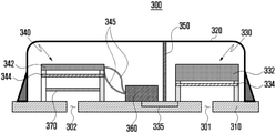
- FIG. 3 is a diagram illustrating the configuration of a microphone according to a first embodiment of the disclosure.
- the microphone 300 may include a substrate 310 , a casing 320 , a first audio generator 330 , a second audio generator 340 , a noise barrier 350 , a signal processor 360 and a delay plate 370 .
- the substrate 310 may be provided in an electronic device (e.g., the electronic device 101 in FIG. 1 ).
- the substrate 310 may include a first hole 301 and second hole 302 to which an audio signal from the outside is input.
- the first hole 301 and the second hole 302 may be formed to perpendicularly penetrate the substrate 310 .
- Audio signals input through the first hole 301 and the second hole 302 may be transmitted to the first audio generator 330 and the second audio generator 340 , respectively.
- the first hole 301 and the second hole 302 may be spaced apart from each other at a given interval.
- the substrate 310 may include a printed circuit board (PCB) or a flexible printed circuit board (FPCB).
- an audio signal input through the first hole 301 and the second hole 302 may be a user command from the user of an electronic device (e.g., the electronic device 101 in FIG. 1 ), which is delivered through a voice.
- the casing 320 may have a first side (e.g., top) open and a second side (e.g., bottom) closed.
- the casing 320 can protect elements, such as the first audio generator 330 , the second audio generator 340 , the signal processor 360 and the delay plate 370 , by surrounding the elements.
- the casing 320 may have the first side coupled to the substrate 310 to form a resonant space therein.
- the casing 320 may be made of metal or a ceramic material.
- the first audio generator 330 may be connected to the signal processor 360 through a wire 335 .
- the first audio generator 330 may convert an audio signal, input through the first hole 301 of the substrate 310 , into an electrical signal.
- the first audio generator 330 may generate a first audio output signal in response to an audio command from a user input through the first hole 301 of the substrate 310 , and may transmit the generated first audio output signal to the signal processor 360 through the wire 335 .
- the first audio generator 330 may include a first plate 332 (e.g., fixing film) and a first membrane 334 (e.g., vibration film).
- the first audio generator 330 may be positioned on the substrate 310 near the first hole 301 .
- the first membrane 334 may be exposed by the first hole 301 .
- the first plate 332 and the first membrane 334 may be spaced apart from each other at a given interval.
- the first plate 332 and the first membrane 334 may include a plurality of holes (e.g., holes 375 in FIG. 4 ) so that an audio signal input through the first hole 301 can pass through the first plate 332 and the first membrane 334 .
- the first plate 332 may be fixed, and the first membrane 334 may be flexible in such a way as to generate vibration. For example, when an audio signal is input through the first hole 301 of the substrate 310 , the first membrane 334 may vibrate. When the first membrane 334 vibrates, an interval between the first plate 332 and the first membrane 334 may be changed. In response to the change, capacitance between the first plate 332 and the first membrane 334 is changed. The changed capacitance may be converted into an electrical signal.
- the first plate 332 may include a first MEMS back plate, and the first membrane 334 may include a first MEMS membrane.
- the second audio generator 340 may be connected to the signal processor 360 through a connection line 345 .
- the second audio generator 340 may convert an audio signal, input through the second hole 302 of the substrate 310 , into an electrical signal.
- the second audio generator 340 may generate a second audio output signal in response to an audio command from a user input through the second hole 302 of the substrate 310 , and may transmit the generated second audio output signal to the signal processor 360 through the connection line 345 .
- the second audio generator 340 may include a second plate 342 (e.g., fixing film) and a second membrane 344 (e.g., vibration film).
- the second audio generator 340 may be positioned on the substrate 310 near the second hole 302 .
- the second plate 342 and the second membrane 344 may be spaced apart from each other at a given interval.
- the second plate 342 and the second membrane 344 may include a plurality of holes (e.g., the holes 375 in FIG. 4 ) so that an audio signal input through the second hole 302 can pass through the second plate 342 and the second membrane 344 .
- the second plate 342 may be fixed, and the second membrane 344 may be flexible in such a way as to generate vibration.
- the second membrane 344 may vibrate.
- an interval between the second plate 342 and the second membrane 344 may be changed.
- capacitance between the second plate 342 and the second membrane 344 is changed.
- the changed capacitance may be converted into an electrical signal.
- the second plate 342 may include a second MEMS back plate, and the second membrane 344 may include a second MEMS membrane.
- vibration when an electric current is supplied from the signal processor 360 , vibration may occur because electric charges are generated between the second plate 342 and second membrane 344 of the second audio generator 340 .
- capacitance between the second plate 342 and the second membrane 344 is changed. The changed capacitance may be converted into an electrical signal.
- the first audio generator 330 and the second audio generator 340 may be disposed at locations corresponding to the first hole 301 and second hole 302 of the substrate 310 .
- the first audio generator 330 and the second audio generator 340 may be spaced apart from each other at a given interval.
- the first plate 332 may be thicker than the second plate 342 .
- the first plate 332 may have relatively lower sensitivity than the second plate 342 .
- the second plate 342 may have relatively higher sensitivity than the first plate 332 .
- the sensitivity of the first plate 332 may be ⁇ 42 dB
- the sensitivity of the second plate 342 may be ⁇ 30 dB. Saturation may not easily occur in the first plate 332 because the first plate 332 has relatively lower sensitivity than the second plate 342 .
- the second plate 342 may accommodate a small audio signal because the second plate has relatively higher sensitivity than the first plate 332 .
- the noise barrier 350 may be positioned between the first audio generator 330 and the second audio generator 340 .
- the noise barrier 350 may have a first side (e.g., top) coupled to the casing 350 and a second side (e.g., bottom) coupled to the substrate 310 .
- the noise barrier 350 may separate the spaces of the first audio generator 330 and the second audio generator 340 .
- the noise barrier 350 can prevent interference from occurring between a first audio output signal generated by the first audio generator 330 and a second audio output signal generated by the second audio generator 340 .
- the signal processor 360 may be positioned on the substrate 310 .
- the signal processor 360 may be positioned adjacent to the second audio generator 340 .
- the signal processor 360 may be electrically connected to the first audio generator 330 through the wire 335 .
- the signal processor 360 may be electrically connected to the second audio generator 340 through the connection line 345 .
- the signal processor 360 may supply power to the first audio generator 330 and the second audio generator 340 .
- the signal processor 360 may process audio signals transmitted by the first audio generator 330 and the second audio generator 340 .
- the signal processor 360 may compose a first audio output signal and second audio output signal transmitted by the first audio generator 330 and the second audio generator 340 .
- the signal processor 360 may analyze audio signals input through the first hole 301 and second hole 302 of the substrate 310 , and may remove a noise signal (e.g., loud noise) of a threshold or more.
- the signal processor 360 may output, to an electronic device (e.g., the electronic device 101 in FIG. 1 ), an audio command from a user, from which a noise signal of a threshold or more has been removed.
- the signal processor 360 may include an application specific integrated circuit (ASIC).
- ASIC application specific integrated circuit
- the signal processor 360 may include the audio signal processor 240 disclosed in FIG. 2 .
- the delay plate 370 may be included in the second audio generator 340 .
- the delay plate 370 may be exposed by the second hole 302 of the substrate 310 .
- the delay plate 370 may be positioned between the second membrane 344 and the substrate 310 .
- the delay plate 370 can prevent saturation from occurring in the microphone 300 by delaying the time taken for an audio signal, input through the second hole 302 of the substrate 310 , to reach the second membrane 344 of the second audio generator 340 .
- the delay plate 370 may delay the phase of an audio signal, input to the second membrane 344 , compared to the first membrane 334 .
- the delay plate 370 may be a phase-delayed filter or a phase-delayed mesh.
- the delay plate 370 may be made of metal or fabric.
- FIG. 4 is a diagram illustrating the configuration of a delay plate according to various embodiments of the disclosure.
- the delay plate 370 may include the plurality of holes 375 .
- the sizes of the holes 375 may be different.
- the phase delay rate of an audio signal in the delay plate 370 may be different depending on the sizes of the holes 375 .
- the same holes as the holes 375 formed in the delay plate 370 may be formed in the first plate 332 and first membrane 334 of the first audio generator 330 and the second plate 342 and second membrane 344 of the second audio generator 340 .
- the sensitivity of an audio signal may different depending on the number, pattern, etc. of the holes 375 formed in the first plate 332 and first membrane 334 of the first audio generator 330 and the second plate 342 and second membrane 344 of the second audio generator 340 .
- the sensitivity may be higher as the size of the hole 375 is smaller, and the sensitivity may be lower as the size of the hole 375 is greater.
- FIG. 5 is a diagram describing the configuration and operation of the signal processor according to various embodiments of the disclosure.
- the signal processor 360 may include an amplifier 362 and an inverter 364 .
- the amplifier 362 may amplify audio signals input through the first hole 301 and second hole 302 of the substrate 310 .
- the inverter 364 may invert the signals amplified through the amplifier 362 .
- the first audio generator 330 and the second audio generator 340 may receive audio signals through the first hole 301 and second hole 302 of the substrate 310 .
- the audio signal may include an audio command from a user or noise of a threshold.
- the audio signal of the first audio generator 330 that exceeds the threshold may be transmitted to the signal processor 360 .
- the audio signal transmitted to the signal processor 360 may be amplified through the amplifier 362 by a gain difference (e.g., 12 dB) between the first audio generator 330 and the second audio generator 340 .
- a gain difference e.g. 12 dB
- the signal amplified through the amplifier 362 may be inverted through the inverter 364 and transmitted to the second audio generator 340 .
- the second audio generator 340 may output the signal from the signal processor 360 by controlling a noise signal that belongs to the signal and that may cause saturation to a given level.
- the signal processor 360 may compose the audio signal of the second audio generator 340 and a signal inverted through the inverter 364 .
- the signal inverted through the inverter 364 has a phase opposite the phase of the audio signal of the second audio generator 340 . Accordingly, when the signal of the first audio generator 340 and the audio signal of the second audio generator 340 are composed, the signal of the first audio generator 330 can be removed.
- FIG. 6 is a flowchart illustrating a method of controlling the microphone according to various embodiments of the disclosure.
- FIG. 6 may be an operation of the signal processor if the first plate 332 of the first audio generator 330 is thicker than the second plate 342 of the second audio generator 340 . That is, the first plate 332 may have relatively lower sensitivity than the second plate 342 .
- the sensitivity of the first plate 332 may be ⁇ 42 dB
- the sensitivity of the second plate 342 may be ⁇ 30 dB.
- the first audio generator 330 and the second audio generator 340 may receive audio signals through the first hole 301 and second hole 302 of the substrate 310 .
- the signal processor 360 may detect and determine which one of the audio signals of the first audio generator 330 and the second audio generator 340 exceeds a threshold.
- the signal processor 360 may amplify the audio signal exceeding the threshold through the amplifier 362 .
- the signal processor 360 may invert the audio signal, amplified at operation 430 , through the inverter 364 .
- the signal processor 360 may transmit the audio signal, inverted at operation 440 , to the second audio generator 340 .
- the signal processor 360 may remove a noise signal (e.g., a signal exceeding the threshold) which may cause saturation from the audio signal, received from the second audio generator 340 , by controlling a movement of the second membrane 344 of the second audio generator 340 to a given level simultaneously with operation 450 , and may output a corresponding signal.
- a noise signal e.g., a signal exceeding the threshold
- FIG. 7 is a diagram illustrating the configuration of a microphone according to a second embodiment of the disclosure.
- the microphone 300 may include a substrate 310 , a casing 320 , a first audio generator 330 , a second audio generator 340 , a noise barrier 350 , a signal processor 360 and a delay plate 370 .
- the first audio generator 330 may include a first plate 332 and a first membrane 334 .
- the second audio generator 340 may include a second plate 342 and a second membrane 344 .
- the configurations and functions of the first membrane 334 and the second membrane 344 may be different, but the locations, functions and operations of the remaining elements may be the same compared to the microphone 300 disclosed in FIG. 3 .
- the thickness of the first membrane 334 may be thicker than the thickness of the second membrane 344 (e.g., approximately twice).
- the first membrane 334 may have relatively lower sensitivity than the second membrane 344 .
- the sensitivity of the first membrane 334 may be ⁇ 36 dB
- the sensitivity of the second membrane 344 may be ⁇ 30 dB.
- a difference between the sensitivities of the first membrane 334 and the second membrane 344 may be 6 dB. Saturation may not easily occur in the microphone 300 because the first membrane 334 has relatively lower sensitivity than the second membrane 344 .
- the second membrane 344 may accommodate a small audio signal because the second membrane has relatively higher sensitivity than the first membrane 334 .
- FIG. 8 is a diagram illustrating the configuration of a microphone according to a third embodiment of the disclosure.
- the microphone 300 may include a substrate 310 , a casing 320 , a first audio generator 330 , a second audio generator 340 , a noise barrier 350 , a signal processor 360 and a delay plate 370 .
- the first audio generator 330 may include a first plate 332 and a first membrane 334 .
- the second audio generator 340 may include a second plate 342 and a second membrane 344 .
- the microphone 300 disclosed in FIG. 8 only the configurations and functions of the first audio generator 330 and the second audio generator 340 may be different, but the locations, functions and operations of the remaining elements may be the same compared to the microphone 300 disclosed in FIG. 3 .
- the area (e.g., width) of the first audio generator 330 may be smaller than the area (e.g., approximately twice) of the second audio generator 340 .
- the first audio generator 330 may have relatively lower sensitivity than the second audio generator 340 .
- the sensitivity of the first audio generator 330 may be ⁇ 36 dB
- the sensitivity of the second audio generator 340 may be ⁇ 30 dB.
- a difference between the sensitivities of the first audio generator 330 and the second audio generator 340 may be 6 dB. Saturation may not easily occur in the microphone 300 because the first audio generator 330 has relatively lower sensitivity than the second audio generator 340 .
- the second audio generator 340 can accommodate a small audio signal because the second audio generator has relatively higher sensitivity than the first audio generator 330 .
- FIG. 9 is a diagram illustrating the configuration of a microphone according to a fourth embodiment of the disclosure.
- the microphone 300 may include a substrate 310 , a casing 320 , a first audio generator 330 , a second audio generator 340 , a noise barrier 350 , a signal processor 360 and a delay plate 370 .
- the first audio generator 330 may include a first plate 332 and a first membrane 334 .
- the second audio generator 340 may include a second plate 342 and a second membrane 344 .
- the first membrane 334 and the second membrane 344 may be different, but the locations, functions and operations of the remaining elements may be the same compared to the microphone 300 disclosed in FIG. 3 .
- the first membrane 334 of the first audio generator 330 and the second membrane 344 of the second audio generator 340 may include the plurality of holes 375 .
- the sensitivity of an audio signal may be different depending on the number, pattern, etc. of the holes 375 formed in the first membrane 334 and the second membrane 344 .
- the sensitivity may be higher as the size of the hole 375 is smaller, and the sensitivity may be lower as the size of the hole 375 is greater.
- the size of the hole 375 formed in the first membrane 334 may be greater than the size (e.g., approximately twice) of the hole 375 formed in the second membrane 344 .
- the first membrane 334 may have relatively lower sensitivity than the second membrane 344 .
- the sensitivity of the first membrane 334 may be ⁇ 36 dB
- the sensitivity of the second membrane 344 may be ⁇ 30 dB.
- a difference between the sensitivities of the first membrane 334 and the second membrane 344 may be 6 dB. Saturation may not easily occur in the microphone 300 because the first membrane 334 has relatively lower sensitivity than the second membrane 344 .
- the second membrane 344 can accommodate a small audio signal because the second membrane has relatively higher sensitivity than the first membrane 334 .
- an electronic device e.g., the electronic device 101 in FIG. 1
- a smartphone such as a smartphone, television (TV), a vehicle, a washing machine, a refrigerator, a wearable device or a drone
- TV television
- vehicle such as a motorcycle
- washing machine such as a washing machine
- refrigerator such as a refrigerator
- wearable device such as a washing machine
- drone such as a washing machine, a refrigerator, a wearable device or a drone
- the microphone configured as described above.
Landscapes
- Engineering & Computer Science (AREA)
- Physics & Mathematics (AREA)
- Acoustics & Sound (AREA)
- Signal Processing (AREA)
- Health & Medical Sciences (AREA)
- Otolaryngology (AREA)
- General Health & Medical Sciences (AREA)
- Computational Linguistics (AREA)
- Audiology, Speech & Language Pathology (AREA)
- Human Computer Interaction (AREA)
- Multimedia (AREA)
- Quality & Reliability (AREA)
- Circuit For Audible Band Transducer (AREA)
Abstract
Description
Claims (15)
Applications Claiming Priority (3)
| Application Number | Priority Date | Filing Date | Title |
|---|---|---|---|
| KR10-2017-0132307 | 2017-10-12 | ||
| KR1020170132307A KR102378675B1 (en) | 2017-10-12 | 2017-10-12 | Microphone, electronic device including the microphone and method for controlling the electronic device |
| PCT/KR2018/011734 WO2019074238A1 (en) | 2017-10-12 | 2018-10-04 | Microphone, electronic apparatus including microphone and method for controlling electronic apparatus |
Publications (2)
| Publication Number | Publication Date |
|---|---|
| US20200273478A1 US20200273478A1 (en) | 2020-08-27 |
| US11227619B2 true US11227619B2 (en) | 2022-01-18 |
Family
ID=66101568
Family Applications (1)
| Application Number | Title | Priority Date | Filing Date |
|---|---|---|---|
| US16/645,857 Active US11227619B2 (en) | 2017-10-12 | 2018-10-04 | Microphone, electronic apparatus including microphone and method for controlling electronic apparatus |
Country Status (4)
| Country | Link |
|---|---|
| US (1) | US11227619B2 (en) |
| EP (1) | EP3664469B1 (en) |
| KR (1) | KR102378675B1 (en) |
| WO (1) | WO2019074238A1 (en) |
Families Citing this family (5)
| Publication number | Priority date | Publication date | Assignee | Title |
|---|---|---|---|---|
| US11367458B2 (en) | 2020-08-21 | 2022-06-21 | Waymo Llc | Accelerometer inside of a microphone unit |
| CN112565999A (en) * | 2020-11-23 | 2021-03-26 | 温州稳步鞋业有限公司 | Energy-saving environment-friendly sound intensity detection mechanism for sound equipment capable of avoiding noise pollution |
| TWI852144B (en) * | 2022-10-26 | 2024-08-11 | 緯創資通股份有限公司 | Smart speaker having speaker module and microphone |
| WO2024174074A1 (en) * | 2023-02-21 | 2024-08-29 | 瑞声声学科技(深圳)有限公司 | Microphone module |
| CN116405857B (en) * | 2023-06-08 | 2023-08-22 | 苏州敏芯微电子技术股份有限公司 | A noise reduction MEMS microphone and electronic equipment |
Citations (15)
| Publication number | Priority date | Publication date | Assignee | Title |
|---|---|---|---|---|
| KR19980082538A (en) | 1997-05-07 | 1998-12-05 | 조흥기 | Noise canceling device |
| US20070047744A1 (en) * | 2005-08-23 | 2007-03-01 | Harney Kieran P | Noise mitigating microphone system and method |
| WO2008014324A2 (en) | 2006-07-25 | 2008-01-31 | Analog Devices, Inc. | Multiple microphone system |
| US20100183167A1 (en) * | 2009-01-20 | 2010-07-22 | Nokia Corporation | Multi-membrane microphone for high-amplitude audio capture |
| US20100226507A1 (en) * | 2009-03-03 | 2010-09-09 | Funai Electric Co., Ltd. | Microphone Unit |
| US20120250897A1 (en) | 2011-04-02 | 2012-10-04 | Mwm Acoustics, Llc | Dual Cell MEMS Assembly |
| JP2013251774A (en) | 2012-05-31 | 2013-12-12 | Omron Corp | Capacitance type sensor, acoustic sensor, and microphone |
| US20140211957A1 (en) * | 2013-01-31 | 2014-07-31 | Invensense, Inc. | Noise Mitigating Microphone System |
| US20140355784A1 (en) * | 2013-05-29 | 2014-12-04 | Bse Co., Ltd. | Directional microphone and operating method thereof |
| US20150010191A1 (en) * | 2013-07-03 | 2015-01-08 | Harman International Industries, Inc. | Gradient micro-electro-mechanical systems (mems) microphone |
| US20150125003A1 (en) | 2013-11-06 | 2015-05-07 | Infineon Technologies Ag | System and Method for a MEMS Transducer |
| US20160167946A1 (en) * | 2013-07-05 | 2016-06-16 | Cirrus Logic International Semiconductor Ltd. | Mems device and process |
| CN105848075A (en) * | 2015-01-15 | 2016-08-10 | 中芯国际集成电路制造(上海)有限公司 | MEMS (Micro Electro Mechanical Systems) device, manufacturing method thereof and electronic device |
| KR20160127326A (en) | 2016-06-24 | 2016-11-03 | (주)이미지스테크놀로지 | MEMS microphone |
| US20160345106A1 (en) * | 2014-01-16 | 2016-11-24 | Epcos Ag | Multi-mems module |
-
2017
- 2017-10-12 KR KR1020170132307A patent/KR102378675B1/en active Active
-
2018
- 2018-10-04 US US16/645,857 patent/US11227619B2/en active Active
- 2018-10-04 WO PCT/KR2018/011734 patent/WO2019074238A1/en not_active Ceased
- 2018-10-04 EP EP18865648.2A patent/EP3664469B1/en active Active
Patent Citations (19)
| Publication number | Priority date | Publication date | Assignee | Title |
|---|---|---|---|---|
| KR19980082538A (en) | 1997-05-07 | 1998-12-05 | 조흥기 | Noise canceling device |
| US20070047744A1 (en) * | 2005-08-23 | 2007-03-01 | Harney Kieran P | Noise mitigating microphone system and method |
| WO2008014324A2 (en) | 2006-07-25 | 2008-01-31 | Analog Devices, Inc. | Multiple microphone system |
| US20080049953A1 (en) | 2006-07-25 | 2008-02-28 | Analog Devices, Inc. | Multiple Microphone System |
| US20100183167A1 (en) * | 2009-01-20 | 2010-07-22 | Nokia Corporation | Multi-membrane microphone for high-amplitude audio capture |
| KR20110106935A (en) | 2009-01-20 | 2011-09-29 | 노키아 코포레이션 | Method and apparatus for high amplitude audio capture |
| US20100226507A1 (en) * | 2009-03-03 | 2010-09-09 | Funai Electric Co., Ltd. | Microphone Unit |
| US20120250897A1 (en) | 2011-04-02 | 2012-10-04 | Mwm Acoustics, Llc | Dual Cell MEMS Assembly |
| JP2013251774A (en) | 2012-05-31 | 2013-12-12 | Omron Corp | Capacitance type sensor, acoustic sensor, and microphone |
| US20150104048A1 (en) | 2012-05-31 | 2015-04-16 | Omron Corporation | Capacitance sensor, acoustic sensor, and microphone |
| US20140211957A1 (en) * | 2013-01-31 | 2014-07-31 | Invensense, Inc. | Noise Mitigating Microphone System |
| US20140355784A1 (en) * | 2013-05-29 | 2014-12-04 | Bse Co., Ltd. | Directional microphone and operating method thereof |
| KR20140140292A (en) | 2013-05-29 | 2014-12-09 | 현대자동차주식회사 | Apparatus for directional microphone and operating method thereof |
| US20150010191A1 (en) * | 2013-07-03 | 2015-01-08 | Harman International Industries, Inc. | Gradient micro-electro-mechanical systems (mems) microphone |
| US20160167946A1 (en) * | 2013-07-05 | 2016-06-16 | Cirrus Logic International Semiconductor Ltd. | Mems device and process |
| US20150125003A1 (en) | 2013-11-06 | 2015-05-07 | Infineon Technologies Ag | System and Method for a MEMS Transducer |
| US20160345106A1 (en) * | 2014-01-16 | 2016-11-24 | Epcos Ag | Multi-mems module |
| CN105848075A (en) * | 2015-01-15 | 2016-08-10 | 中芯国际集成电路制造(上海)有限公司 | MEMS (Micro Electro Mechanical Systems) device, manufacturing method thereof and electronic device |
| KR20160127326A (en) | 2016-06-24 | 2016-11-03 | (주)이미지스테크놀로지 | MEMS microphone |
Non-Patent Citations (3)
| Title |
|---|
| ISA/KR, International Search Report and Written Opinion of the International Searching Authority, International Application No. PCT/KR2018/011734, dated Feb. 20, 2019, 13 pages. |
| Korean Intellectual Property Office, "Office Action" dated Jul. 19, 2021, in connection with Korean Patent Application No. 10-2017-0132307, 16 pages. |
| Supplementary European Search Report dated Oct. 1, 2020 in connection with European Application No. 18865648.2, 8 pages. |
Also Published As
| Publication number | Publication date |
|---|---|
| EP3664469B1 (en) | 2022-12-07 |
| KR20190041169A (en) | 2019-04-22 |
| EP3664469A4 (en) | 2020-11-04 |
| WO2019074238A1 (en) | 2019-04-18 |
| US20200273478A1 (en) | 2020-08-27 |
| EP3664469A1 (en) | 2020-06-10 |
| KR102378675B1 (en) | 2022-03-25 |
Similar Documents
| Publication | Publication Date | Title |
|---|---|---|
| US11227619B2 (en) | Microphone, electronic apparatus including microphone and method for controlling electronic apparatus | |
| US12022019B2 (en) | Method and electronic device for adjusting output level of speaker on basis of distance from external electronic device | |
| EP3035702A1 (en) | Acoustic input module and electronic device including the same | |
| US11159899B2 (en) | Eartip including foreign matter inflow prevention portion and electronic device including the same | |
| US11962966B2 (en) | Headset including in-ear microphone | |
| US11204882B2 (en) | Electronic device for controlling external conversion device | |
| US11238880B2 (en) | Method for acquiring noise-refined voice signal, and electronic device for performing same | |
| US12363477B2 (en) | Method and device for controlling microphone input/output by wireless audio device during multi-recording in electronic device | |
| US11889274B2 (en) | Electronic device for sensing temperature of speaker, and operation method thereof | |
| US10609480B2 (en) | Method and electronic device for executing function using a plurality of microphones | |
| US11546693B2 (en) | Method for generating audio signal using plurality of speakers and microphones and electronic device thereof | |
| US11190891B2 (en) | Method for determining whether error has occurred in microphone on basis of magnitude of audio signal acquired through microphone, and electronic device thereof | |
| US10388301B2 (en) | Method for processing audio signal and electronic device for supporting the same | |
| US11423912B2 (en) | Method and electronic device for processing audio signal on basis of resolution set on basis of volume of audio signal | |
| US11398242B2 (en) | Electronic device for determining noise control parameter on basis of network connection information and operating method thereof | |
| US11799253B2 (en) | Electronic apparatus for supporting high-speed charging and audio signal transmission/reception functions | |
| US12418746B2 (en) | Method for processing audio data and electronic device supporting same | |
| EP4336504A1 (en) | Audio signal processing method and electronic device supporting same | |
| KR102396558B1 (en) | Earjack connection device for earphone antenna and electronic apparatus including the earjack connection device | |
| US12069458B2 (en) | Electronic device and method for generating audio signal | |
| KR102862970B1 (en) | Method for processing audio data and electronic device supporting the same | |
| EP4697742A1 (en) | Electronic device, method, and non-transitory computer-readable recording medium for outputting audio signals through different types of audio circuits | |
| EP4589986A1 (en) | Electronic device and method for generating vibration sound signal | |
| KR20260005705A (en) | Electronic device, method, and non-transitory computer readable storage medium for outputting audio signal via heterogeneous audio circuits |
Legal Events
| Date | Code | Title | Description |
|---|---|---|---|
| AS | Assignment |
Owner name: SAMSUNG ELECTRONICS CO., LTD., KOREA, REPUBLIC OF Free format text: ASSIGNMENT OF ASSIGNORS INTEREST;ASSIGNORS:PARK, JEHEON;KIM, KIWON;KIM, SUNGHOON;REEL/FRAME:052064/0947 Effective date: 20200203 |
|
| FEPP | Fee payment procedure |
Free format text: ENTITY STATUS SET TO UNDISCOUNTED (ORIGINAL EVENT CODE: BIG.); ENTITY STATUS OF PATENT OWNER: LARGE ENTITY |
|
| STPP | Information on status: patent application and granting procedure in general |
Free format text: NON FINAL ACTION MAILED |
|
| STPP | Information on status: patent application and granting procedure in general |
Free format text: RESPONSE TO NON-FINAL OFFICE ACTION ENTERED AND FORWARDED TO EXAMINER |
|
| STPP | Information on status: patent application and granting procedure in general |
Free format text: FINAL REJECTION MAILED |
|
| STPP | Information on status: patent application and granting procedure in general |
Free format text: RESPONSE AFTER FINAL ACTION FORWARDED TO EXAMINER |
|
| STPP | Information on status: patent application and granting procedure in general |
Free format text: NOTICE OF ALLOWANCE MAILED -- APPLICATION RECEIVED IN OFFICE OF PUBLICATIONS |
|
| STPP | Information on status: patent application and granting procedure in general |
Free format text: AWAITING TC RESP., ISSUE FEE NOT PAID |
|
| STPP | Information on status: patent application and granting procedure in general |
Free format text: NOTICE OF ALLOWANCE MAILED -- APPLICATION RECEIVED IN OFFICE OF PUBLICATIONS |
|
| STPP | Information on status: patent application and granting procedure in general |
Free format text: PUBLICATIONS -- ISSUE FEE PAYMENT VERIFIED |
|
| STCF | Information on status: patent grant |
Free format text: PATENTED CASE |
|
| MAFP | Maintenance fee payment |
Free format text: PAYMENT OF MAINTENANCE FEE, 4TH YEAR, LARGE ENTITY (ORIGINAL EVENT CODE: M1551); ENTITY STATUS OF PATENT OWNER: LARGE ENTITY Year of fee payment: 4 |