US11227242B2 - System and method for automatically triggering incident intervention - Google Patents
System and method for automatically triggering incident intervention Download PDFInfo
- Publication number
- US11227242B2 US11227242B2 US16/115,108 US201816115108A US11227242B2 US 11227242 B2 US11227242 B2 US 11227242B2 US 201816115108 A US201816115108 A US 201816115108A US 11227242 B2 US11227242 B2 US 11227242B2
- Authority
- US
- United States
- Prior art keywords
- user interface
- risk factor
- worksite
- condition
- location
- Prior art date
- Legal status (The legal status is an assumption and is not a legal conclusion. Google has not performed a legal analysis and makes no representation as to the accuracy of the status listed.)
- Active, expires
Links
Images


Classifications
-
- G—PHYSICS
- G06—COMPUTING OR CALCULATING; COUNTING
- G06Q—INFORMATION AND COMMUNICATION TECHNOLOGY [ICT] SPECIALLY ADAPTED FOR ADMINISTRATIVE, COMMERCIAL, FINANCIAL, MANAGERIAL OR SUPERVISORY PURPOSES; SYSTEMS OR METHODS SPECIALLY ADAPTED FOR ADMINISTRATIVE, COMMERCIAL, FINANCIAL, MANAGERIAL OR SUPERVISORY PURPOSES, NOT OTHERWISE PROVIDED FOR
- G06Q10/00—Administration; Management
- G06Q10/06—Resources, workflows, human or project management; Enterprise or organisation planning; Enterprise or organisation modelling
- G06Q10/063—Operations research, analysis or management
- G06Q10/0631—Resource planning, allocation, distributing or scheduling for enterprises or organisations
- G06Q10/06311—Scheduling, planning or task assignment for a person or group
- G06Q10/063114—Status monitoring or status determination for a person or group
-
- F—MECHANICAL ENGINEERING; LIGHTING; HEATING; WEAPONS; BLASTING
- F16—ENGINEERING ELEMENTS AND UNITS; GENERAL MEASURES FOR PRODUCING AND MAINTAINING EFFECTIVE FUNCTIONING OF MACHINES OR INSTALLATIONS; THERMAL INSULATION IN GENERAL
- F16P—SAFETY DEVICES IN GENERAL; SAFETY DEVICES FOR PRESSES
- F16P3/00—Safety devices acting in conjunction with the control or operation of a machine; Control arrangements requiring the simultaneous use of two or more parts of the body
- F16P3/12—Safety devices acting in conjunction with the control or operation of a machine; Control arrangements requiring the simultaneous use of two or more parts of the body with means, e.g. feelers, which in case of the presence of a body part of a person in or near the danger zone influence the control or operation of the machine
- F16P3/14—Safety devices acting in conjunction with the control or operation of a machine; Control arrangements requiring the simultaneous use of two or more parts of the body with means, e.g. feelers, which in case of the presence of a body part of a person in or near the danger zone influence the control or operation of the machine the means being photocells or other devices sensitive without mechanical contact
-
- E—FIXED CONSTRUCTIONS
- E02—HYDRAULIC ENGINEERING; FOUNDATIONS; SOIL SHIFTING
- E02F—DREDGING; SOIL-SHIFTING
- E02F9/00—Component parts of dredgers or soil-shifting machines, not restricted to one of the kinds covered by groups E02F3/00 - E02F7/00
- E02F9/26—Indicating devices
- E02F9/261—Surveying the work-site to be treated
- E02F9/262—Surveying the work-site to be treated with follow-up actions to control the work tool, e.g. controller
-
- G—PHYSICS
- G01—MEASURING; TESTING
- G01D—MEASURING NOT SPECIALLY ADAPTED FOR A SPECIFIC VARIABLE; ARRANGEMENTS FOR MEASURING TWO OR MORE VARIABLES NOT COVERED IN A SINGLE OTHER SUBCLASS; TARIFF METERING APPARATUS; MEASURING OR TESTING NOT OTHERWISE PROVIDED FOR
- G01D21/00—Measuring or testing not otherwise provided for
- G01D21/02—Measuring two or more variables by means not covered by a single other subclass
-
- G—PHYSICS
- G06—COMPUTING OR CALCULATING; COUNTING
- G06Q—INFORMATION AND COMMUNICATION TECHNOLOGY [ICT] SPECIALLY ADAPTED FOR ADMINISTRATIVE, COMMERCIAL, FINANCIAL, MANAGERIAL OR SUPERVISORY PURPOSES; SYSTEMS OR METHODS SPECIALLY ADAPTED FOR ADMINISTRATIVE, COMMERCIAL, FINANCIAL, MANAGERIAL OR SUPERVISORY PURPOSES, NOT OTHERWISE PROVIDED FOR
- G06Q10/00—Administration; Management
- G06Q10/06—Resources, workflows, human or project management; Enterprise or organisation planning; Enterprise or organisation modelling
- G06Q10/063—Operations research, analysis or management
- G06Q10/0631—Resource planning, allocation, distributing or scheduling for enterprises or organisations
- G06Q10/06316—Sequencing of tasks or work
-
- G—PHYSICS
- G08—SIGNALLING
- G08G—TRAFFIC CONTROL SYSTEMS
- G08G1/00—Traffic control systems for road vehicles
- G08G1/20—Monitoring the location of vehicles belonging to a group, e.g. fleet of vehicles, countable or determined number of vehicles
-
- H—ELECTRICITY
- H04—ELECTRIC COMMUNICATION TECHNIQUE
- H04W—WIRELESS COMMUNICATION NETWORKS
- H04W4/00—Services specially adapted for wireless communication networks; Facilities therefor
- H04W4/02—Services making use of location information
- H04W4/023—Services making use of location information using mutual or relative location information between multiple location based services [LBS] targets or of distance thresholds
-
- G—PHYSICS
- G05—CONTROLLING; REGULATING
- G05D—SYSTEMS FOR CONTROLLING OR REGULATING NON-ELECTRIC VARIABLES
- G05D1/00—Control of position, course, altitude or attitude of land, water, air or space vehicles, e.g. using automatic pilots
- G05D1/02—Control of position or course in two dimensions
- G05D1/021—Control of position or course in two dimensions specially adapted to land vehicles
- G05D1/0276—Control of position or course in two dimensions specially adapted to land vehicles using signals provided by a source external to the vehicle
Definitions
- This disclosure relates generally to controlling machines at worksites such as construction, industrial, and/or mining sites, and, more specifically, to systems utilizing sensors and data processing techniques to identify incidents and/or intervene in such incidents through machine control.
- a mining site may include excavators, haul trucks, and operators to mine ore or other resources and dispose of waste.
- the operations of such machines and personnel must be coordinated in order to maintain efficiency at the site.
- efficiency may be undermined by accidents at the worksite, because such accidents may result in machine downtime, worker injury, or the like.
- it may be useful to monitor conditions and/or events at the worksite, and take action to prevent incidents based on such monitoring, thereby improving safety at the worksite.
- monitoring and incident prevention may be useful in several different geographical areas, beyond industrial worksites.
- the '242 reference describes a safety device that is worn by a worker in a manufacturing facility.
- the device described in the '242 reference may include a number of sensors that sense environmental conditions around the worker and that tracks the position of the worker.
- the safety device may also include an event trigger that the worker can activate when a notable event or a near miss occurs.
- the environmental data and the events/misses may be stored in a database for purposes of predicting future accidents.
- the '242 reference does not, however, disclose details related to utilizing a network of sensors and communication devices at a worksite to determine risk factors for the worksite and/or automatically intervening to mitigate risks.
- the '242 reference also does not disclose an interactive system that supports identification of risks and remote intervention to mitigate those risks. As a result, incidents such as accidents or equipment failure may not be prevented by the techniques described in the '242 reference.
- Example embodiments of the present disclosure are directed toward overcoming the deficiencies described above.
- a method includes receiving first data captured by a first sensor at a worksite and receiving second data captured by a second sensor at the worksite.
- the first data is indicative of a first condition at a location at the worksite at a first time
- the second data is indicative of a second condition proximate the location at the first time.
- the example method may also include, based at least in part on the first data and the second data, determining a risk factor associated with the location, and generating a first graphical user interface configured for display on a user device.
- the first graphical user interface may include a graphical representation of the worksite, a visual indication of the risk factor at a position on the graphical representation, the position corresponding to the location at the worksite, and a first user interface element associated with at least one of the risk factor or the location.
- the example method may also include receiving a first user input indicative of a user selection of the first user interface element, and based at least in part on the first user input, generating a second graphical user interface configured for display on the user device.
- the second graphical user interface may include additional information about the at least one of the risk factor or the location, the additional information including a second user interface element associated with an action for mitigating a risk associated with the risk factor.
- the example method may also include receiving a second user input indicative of a user selection of the second user interface element, and based at least in part on the second selection information, causing the action to be performed.
- a system in another aspect of the present disclosure, includes one or more processors; and memory storing processor-executable instructions that, when executed by the one or more processors, configure the system to perform acts.
- the acts may include receiving first data captured by a first sensor at a geographic area, the first data being indicative of a first condition at a location at the geographic area at a time, and receiving second data captured by a second sensor at the geographic area, the second data being indicative of a second condition proximate the location substantially at the time.
- the acts may further include, based at least in part on the first data and the second data, determining a risk factor associated with the location and generating a graphical user interface.
- the graphical user interface may include a graphical representation of the geographic area, a visual indication of a value associated with the risk factor at a position on the graphical representation corresponding to the location, and a user interface element associated with at least one of the risk factor or the location.
- the graphical user interface is configured for display on a user device.
- a system includes one or more processors and memory storing processor-executable instructions that, when executed by the one or more processors, configure the system to perform acts.
- the acts may include receiving sensor data associated with a worksite, determining, based at least in part on the sensor data, a first condition associated with a location at the worksite, and determining, based at least in part on the sensor data, a second condition proximate the location.
- the acts may further include determining, based at least in part on the first condition and the second condition, a first risk factor associated with a first portion of the worksite, the first portion including the location and area proximate the location, and determining, based at least in part on the sensor information, a second risk factor associated with a second portion of the worksite adjacent the first portion.
- the acts may also include generating a graphical user interface comprising a graphical representation of the first portion of the worksite and the second portion of the worksite, a visual indication of a first value indicative of the first risk factor positioned in the graphical user interface in association with the first portion, a visual indication of a second value indicative of the second risk factor positioned in the GUI in association with the second portion, a first user interface element associated with at least one of the first value or the first portion, and a second user interface element associated with at least one of the second value or the second portion.
- the graphical user interface is configured for display on a user device.
- the example acts may also include, in response to receiving a user selection of the first user interface element, generating an updated graphical user interface including information about at least one of the first condition or the second condition, the updated graphical user interface being configured for display on the user device.
- FIG. 1 is a perspective view of a worksite in accordance with an example embodiment of the present disclosure.
- FIG. 2 is a schematic representation of a graphical user interface including a graphical representation of the worksite and risks associated with the worksite in accordance with an example embodiment of the present disclosure.
- FIG. 3 is a schematic representation of another graphical user interface in accordance with another example embodiment of the present disclosure.
- FIG. 4 is an example computing environment for automatically triggering incident intervention in accordance with an example embodiment of the present disclosure.
- FIG. 5 is a flowchart illustrating an example method of automatically triggering incident intervention in accordance with an example embodiment of the present disclosure.
- FIG. 6 is a flowchart illustrating an example method of automatically triggering incident intervention in accordance with an example embodiment of the present disclosure.
- FIG. 7 is a flowchart illustrating an example method of automatically triggering incident intervention in accordance with an example embodiment of the present disclosure.
- an example worksite 100 may be a mining location at which a number of operations are being performed.
- the worksite 100 may include an open-pit mine 102 from which ore and/or other materials may be extracted. Additional or alternative operations (not illustrated) performed at the site may include, but are not limited to, tunnel mining, blasting, and/or other mining or landscaping operations.
- aspects of this disclosure may apply to geographic areas and worksites other than a mining site.
- aspects described herein may be applicable to many geographic locales at which coordinated activities are carried out.
- the worksite 100 may be an industrial site, a factory floor, a building construction site, a road construction site, a quarry, a building, a city, or the like.
- features of the worksite may change over time, e.g., as the worksite 100 develops.
- FIG. 1 illustrates an excavator 104 a in the open pit mine 102 and trucks 104 b , 104 c , 104 d performing various hauling and dumping operations throughout the worksite 100 .
- the excavator 104 a and the trucks 104 b - 104 d are only examples.
- machines including but not limited to earth-moving machines, e.g., wheel loaders, dump trucks, backhoes, bulldozers, or material handlers, tankers, e.g., for carrying water or fuel, over-the-road vehicles, work machines, e.g., pavers or compactors, or the like also or alternatively may be present at the worksite 100 .
- work machines e.g., pavers or compactors, or the like
- work machines e.g., pavers or compactors, or the like
- work machines e.g., pavers or compactors, or the like
- the term “machine” may refer to any type of machine that performs some operation associated with an industry such as mining, construction, farming, transportation, oil and gas, manufacturing, or any other industry.
- the machines 104 including but not limited to the excavator 104 a and the trucks 104 b , 104 c , 104 d .
- the worksite 100 may be substantially completely autonomous.
- people or personnel 106 a , 106 b may also be present.
- the personnel 106 a may be a worker or operator in the open-pit mine 102 and the personnel 106 b may be a supervisor or foreman overseeing operations at the worksite 100 .
- additional personnel may also be present at the worksite 100 .
- example tasks or jobs may be ascribed to the personnel 106 for purposes of examples, herein, such are examples only.
- personnel may be performing manual labor, operating the machines 104 , overseeing operations, including operation of the machines 104 , visiting the worksite 100 , and/or performing other tasks.
- One or more of the machines 104 may be configured with or otherwise have access to one or more communication components 108 and/or one or more sensing components 110 .
- one or more of the personnel may have an accompanying one or more communication components 112 and/or one or more sensing components 114 .
- the communication components 108 , 112 may include a transmitter/receiver, including an antenna, to facilitate wireless communication, e.g., via radio frequency (RF) signals, via a wireless network, such as a local area network (LAN) or a wide-area network (WAN), or any other communication protocol.
- RF radio frequency
- the communication components 108 may be configured to communicate with a central hub, e.g., at a fixed location, with the central hub being configured to receive all or substantially all communications and route the communications as appropriate. In other implementations, the communication components 108 may be configured to communicate directly with each other, e.g., via a distributed network. Hybrid networks and/or different communication networks and protocols may alternatively be used; this disclosure is not dependent upon a single arrangement, technology or protocol.
- the communication components 108 , 112 may also include a speaker and/or a microphone to facilitate verbal communication and/or a text input device, e.g., a keypad or touchscreen, to facilitate textual communication.
- the communication components 108 may include one or more radios accessible in the machine 104 , a speaker system in the machine 104 , one or more microphones disposed in the machine 104 , a touch screen in the machine 104 , or the like.
- the communication components 112 may include a radio, mobile phone, tablet device, headset, or other electronic device associated with the personnel 106 and that facilitates communication with the personnel 106 .
- the sensing components 110 may be any number of sensor modalities affixed to or otherwise associated with the machines 104 .
- the sensing components 110 may include location sensors (e.g., GPS, compass, etc.), inertial sensors (e.g., inertial measurement units, accelerometers, magnetometers, gyroscopes, etc.), cameras (e.g., RGB, UV, IR, intensity, depth, etc.), microphones, wheel encoders, environment sensors (e.g., temperature sensors, humidity sensors, light sensors, pressure sensors, etc.), LIDAR sensors, RADAR sensors, ultrasonic transducers, SONAR sensors, etc.
- location sensors e.g., GPS, compass, etc.
- inertial sensors e.g., inertial measurement units, accelerometers, magnetometers, gyroscopes, etc.
- cameras e.g., RGB, UV, IR, intensity, depth, etc.
- microphones wheel encoders
- environment sensors
- the sensing components 110 may be configured to sense conditions external to or internal of (e.g. in a cab of) the machine 104 of which they are associated.
- the sensing components 110 may include cameras trained on an exterior of the machine, e.g., to record video and/or images of an environment of the machine 104 and/or cameras trained on an interior of the machine 104 , e.g., to record video and/or images of an operator of the machine 104 .
- the sensing components 110 may also include wear sensors, e.g., to sense wear of components associated with the machines.
- the sensing components 110 may also include safety-related sensors. For example, seat belt sensors may generate information indicative of whether a seat belt is being used.
- the sensing components 110 may also include multiple sensors of the same type. For example, a plurality of microphones, cameras, or LiDAR sensors may be disposed at different locations on the machine 104 , e.g., to provide information about different portions of the environment of the machine 104 .
- the sensing components 114 may include any number of sensor modalities associated with the personnel 106 .
- the sensing components 114 may include location sensors (e.g., GPS, compass, etc.), inertial sensors (e.g., inertial measurement units, accelerometers, magnetometers, gyroscopes, etc.), cameras (e.g., RGB, UV, IR, intensity, depth, etc.), microphones, environment sensors (e.g., temperature sensors, humidity sensors, light sensors, pressure sensors, etc.).
- the sensing components 114 may also include sensors for measuring attributes of the personnel, e.g., heart rate, blood pressure, calorie expenditure, distance travelled, and the like.
- the sensing components 114 may include safety-related sensors that generate information about whether the personnel is complying with safety regulations.
- the sensing components 114 may include a sensor integrated into a helmet that indicates whether the helmet is worn and/or worn properly and/or a sensor associated with a harness or other safety device used by the personnel 106 .
- the sensing components 114 may be integrated into one or more electronic devices associated with the personnel 106 , including but not limited to a device worn by the personnel 106 , e.g. a head-mounted device, a wrist-mounted device, or the like, or a device carried by the personnel, e.g., a smart phone, a radio, a tablet, a fob, or the like.
- additional sensors may also be disposed at the worksite 100 .
- additional sensors 116 a , 116 b also are illustrated in FIG. 1 .
- the sensors 116 may include one or more sensor modalities, e.g., a motion sensor, a camera, a position sensor, a microphone, a LiDAR sensor, a radar sensor, and/or the like, to surveille conditions at the worksite 100 .
- the additional sensor 116 a may be associated with a workstation 118 , e.g., to sense conditions at or proximate the workstation, and the additional sensor 116 b may be arranged proximate the open-pit mine 102 , e.g., to sense conditions at or proximate the mine 102 .
- the sensors 116 can be placed at locations throughout the worksite 100 to provide additional information about aspects of the worksite 100 .
- the sensors 106 may be disposed to sense conditions at locations that may be of importance and/or may be particularly susceptible to incidents.
- the additional sensors 116 may be associated with other elements, including potentially hazardous elements, at the worksite 100 .
- the additional sensors 116 may be associated with high voltage sources, transformers, pressurized containers, fuel storage, radiation sources, hazard material sites, chemical storage, or the like.
- the worksite 100 may also include a workstation 118 , which may be a room, building, vehicle, or the like, in which one or more of the personnel 108 may be situated.
- the workstation 118 may contain one or more offices in which a supervisor, a foreman, and/or different personnel may be stationed.
- the workstation 118 may be act as a hub, for example, serving as a location at which the various machines and personnel are directed or otherwise controlled.
- the workstation 118 may include one or more computing systems 120 configured to implement processes described herein.
- the computing systems 112 may be configured to receive information from one or more the sensing components 110 , 114 and/or the sensors 116 .
- the worksite 100 may include a number of sensors, at a number of locations, to generate varied types of sensor data. Some of these sensors are conventionally in use at worksites such as the worksite 100 , but often for discrete purposes. For example, in-cab cameras may be used to detect fatigue of users and wear sensors may be used to detect wear of components on machines. However, and as described further herein, in implementations of this disclosure the computing system 120 may receive data from the various sensing components 110 , 114 and/or the sensors 116 , determine risks associated with locations or regions of the worksite 100 , e.g., based on combinations of conditions, and intervene, e.g., by controlling the machines 104 .
- FIG. 1 schematically illustrates that the computing system 120 may include a data processing/condition recognition component 122 .
- the data processing/condition recognition component 122 may analyze sensor data to determine conditions at the worksite.
- a “condition” may refer to an attribute, a state, or a fact about a machine, personnel and/or the worksite generally.
- the data processing/condition recognition component 122 may glean from the sensing components 110 associated with the machines 104 , conditions including locations of the respective machines 104 , current states of the machines 104 (e.g., idle, dumping, excavating) or other conditions.
- the data processing/condition recognition component 122 may also determine, e.g., from the sensing components 114 , conditions of the personnel 106 , including but not limited to a position and/or state of the personnel 106 .
- the data processing/condition recognition component 122 may also determine environment conditions, e.g., temperature, precipitation, or the like, from the additional sensors 116 .
- the data processing/condition recognition component 122 may also analyze received data to determine aforementioned or additional conditions. For example, the data processing/condition recognition component 122 may analyze video or image data to determine a presence and/or identity of personnel at the worksite.
- the data processing/condition recognition component 122 may identify her position and/or identity from video footage captured by a camera associated with the additional sensor 116 a .
- the data processing/condition recognition component 122 may also access information about conditions. For example, upon determining an identify of a machine 104 or personnel 106 , the data processing/condition recognition component 122 may access one or more databases storing information about the machine 104 , e.g., maintenance history, specification, usage history, and the like, and/or about the personnel 106 , e.g., training history, qualifications, and the like. Other example conditions, and methods for determining such conditions, are described further herein.
- the computing system 120 may include a risk assessment component 124 .
- the risk assessment component 124 may include functionality that determines a metric, such as a risk factor, associated with regions of the worksite 100 .
- a risk factor may refer to a score, value, or other metric associated with a likelihood or probability of occurrence of an incident.
- incident may refer to an accident, machine failure, or other occurrence that may result in injury, loss, or other physical, productivity, or economic harm.
- the risk assessment component may consider several conditions at a location or region in the worksite 100 and determine the risk factor based on the several conditions. Accordingly, different geographic locations within the worksite may have different risk factors.
- the risk assessment component 124 may determine a relatively high risk factor for an area proximate the excavator 104 a , e.g., because the personnel 106 a proximate the excavator the personnel 106 a may have limited experience with the excavator 104 a , the personnel 106 a may not be wearing proper safety attire (such as a helmet or other protective gear), and it may be raining. While any one of these conditions may not individually have a high risk factor, the combination of conditions may result in a high risk factor.
- the risk assessment component 124 may be a machine-learning model, e.g., including a neural network, that identifies likelihoods of incidents based on previous incidents and conditions preceding those previous incidents.
- the computing system 120 may also include an intervention component 126 .
- the intervention component 126 may include functionality that controls one or more devices, e.g., the machines 104 and/or devices associated with the personnel 106 , to mitigate risks. For example, when a value associated with a risk factor meets or exceeds a threshold value, the intervention component 126 may determine one or more courses of action for reducing the risk factor, e.g., by altering a condition, and controlling one or more devices to implement such courses of action.
- the intervention component 126 may automatically disable or otherwise limit operation of the excavator 104 a , for example.
- the intervention component 126 may determine actions and enable a user to instruct that such actions be taken, e.g., via interaction with a graphical user interface.
- FIG. 2 is a schematic representation of an example graphical user interface 200 . More specifically, FIG. 2 illustrates a user device 202 having a display 204 .
- the user device 202 is illustrated as a handheld device, such as a tablet device, although in other implementations, the user device may be any number of electronic devices, e.g., a desktop computer, a laptop computer, a smart phone, including a display and facilitating user interaction with the display 204 .
- the display 204 is configured to display or otherwise render the graphical user interface 200 .
- the graphical user interface 200 includes a map 206 including features of the worksite 100 .
- the map 206 may illustrate topographical features such as of the open pit mine 102 .
- the map 206 may also include graphical representations including but not limited to machine representations 208 (e.g., of the machines 104 ) and/or building representations 210 (e.g., of the work station 118 ). Although not shown in FIG. 2 , the map 206 may graphically depict any additional or other features of the worksite 102 .
- the map 206 may include graphical depictions of personnel at the worksite (e.g., the personnel 106 ), of sensing devices located at the worksite (e.g., representations of the sensing device(s) 116 ), other topographical features, such as roads, elevation changes, bodies of water, or the like, and any other structures or features at or near the worksite 100 .
- the map 206 may show hazards or potential hazards at the site, including electrical loads, e.g., transformers, generators, or the like, hazardous materials, e.g., fuel tanks, chemical storage, radiation sources, or the like, and/or other static elements that could be of interest.
- electrical loads e.g., transformers, generators, or the like
- hazardous materials e.g., fuel tanks, chemical storage, radiation sources, or the like, and/or other static elements that could be of interest.
- the map 206 may be partitioned into a number of regions 212 .
- each of the regions 212 is substantially equal in area.
- each of the regions 212 may represent a predetermined area of the worksite 100 .
- each of the regions 21 may approximate a 3 m ⁇ 3 m section of worksite 100 , although smaller or larger sizes are also contemplated.
- the regions 212 are illustrated as being substantially equal in size, they may have different sizes, shapes, or the like.
- the regions 212 are an example only and together, the regions 212 segment the worksite 102 into a grid of sections.
- Conditions and events determined according to implementations described herein may be associated with one or more regions 214 , i.e., based on the location in the worksite 100 of the condition/event, and the regions 214 may be displayed in the graphical user interface 200 to depict information about the condition/event.
- the regions 214 may be designated separately, in a manner that illustrates or portrays a risk factor associated with each of the regions 214 .
- the regions 214 may be differently color-coded.
- the color coding may be used to visually indicate a risk factor, described herein, associated with different regions or locations of the worksite 100 .
- a first region 212 a is designated by the letter A
- a second region 212 b is designated by the letter B
- a third region 212 c is designated by the letter C.
- the first region 212 a is relatively darker than adjacent regions 212
- the second region 212 b be is relatively darker than regions 212 adjacent to it
- the region 212 c is relatively darker than regions adjacent to it.
- the region 212 a is relatively darker than both the region 212 b and the region 212 c . Accordingly, a user viewing the display 204 may determine readily that event A, proximate the region 212 a , has a higher risk factor than other regions 212 on the map. For example, the user may deduce that event A at the region 212 a should be investigated, because it may represent an unsafe event.
- the user may readily determine that the second region 212 b and the third region 212 c have relatively elevated risk factors, e.g., relative to all regions 212 other than the first region 212 a .
- the user may also determine that Event B and/or Event C, e.g., at the respective second and third regions 212 b , 212 c , may be problematic and should be investigated.
- the term “event” may refer to a state or situation resulting from a plurality of conditions.
- the event A may describe the presence of a plurality of conditions at the first region 212 a , which, in the example introduced above in the discussion of FIG. 1 , may include the presence of the excavator 104 a , the presence of the personnel 106 a , details about the excavator 104 a , details about the personnel 106 a , environmental conditions, and/or additional conditions.
- FIG. 2 is provided in grayscale, it will be appreciated that other visual indicators may be used to identify events at the worksite 100 .
- the map 206 may be illustrated as a heat map, with critical regions such as the first region 212 a , the second region 212 b , and/or the region 214 c shown in a different or brighter color than other regions with relatively lower risk factors.
- the first region 214 a may be shown in bright red
- the second and third regions 214 b , 214 c may be shown in lighter red or yellow
- other regions 212 including regions that have no existing conditions or events, may be shown as green.
- the graphical user interface 300 may also include a key to aid the user in understanding the coding scheme.
- visual representations other than a heat map and/or color-coded schemes may be used.
- a number or value corresponding to the risk factor may be presented in association with one or more of the regions 212 .
- the regions may include rankings, which may include letters like those associated with the regions 212 a , 212 b , 212 c . Such ranking may be provided with or without the color scheme.
- the letters may go in order of criticality, i.e., with A being the most critical, B being next, and so forth, although other ordering and/or ranking nomenclature could be used.
- the graphical user interface 200 may include numbers.
- the number “1” can be used in place of the A, number “2” in place of B and so forth.
- only those regions having a risk factor above a predetermined threshold may be enumerated on the graphical user interface 200 .
- the graphical user interface 200 may also allow a user to interact with the graphical user interface 200 .
- the graphical user interface 200 may include user interface controls 214 , 216 , 218 .
- the user interface controls 214 , 216 , 218 may be buttons or other designations on the display 204 of the device 202 via which a user may interact.
- a user may interact with the user interface controls 214 , 216 , 218 by touching the display 204 at a position proximate the user interface control, by selecting the user interface control with a stylus or other selecting device associated with the user device 202 , or otherwise.
- a user may select the user interface control 214 to obtain more information about the event A illustrated as occurring in connection with the first region 212 a .
- the user may select or otherwise interact with the second user interface control 216 to gain additional information about the event B associated with the second region 212 b .
- the user may select or otherwise interact with the third user interface control 218 to gain additional information about the event C associated with the third region 212 c .
- selection of any of the user interface controls 214 , 216 , 218 may cause the user device 202 to render an updated graphical user interface with additional information and enabling additional functionality.
- An example of an updated graphical user interface is illustrated in FIG. 3 , which will be described in more detail below.
- the graphical user interface 200 may also include additional designations, such as a designation 220 , which may indicate to the user that one of the determined events, in this example, Event A, is particularly critical.
- the designation 220 may be displayed when a value of a risk factor is equal to or exceeds a threshold.
- the designation 220 is embodied as a stylized exclamation point in the illustration, other designations 220 may be used.
- the graphical user interface 200 includes the map 206 of the worksite 100 .
- the graphical user interface 200 may also include controls for allowing a user to view other maps, e.g., of those other worksites.
- the map 206 may be presented in association with a first tab 222 a and other maps may be accessible via additional tabs.
- a second map (not shown) may be accessible by selecting a second tab 222 b .
- Other tabs, such as a third tab 222 c may allow a user to view additional sites or locations.
- the tabs 222 a , 222 b , 222 c are one example of an arrangement via which a user may view different maps; other arrangements also are contemplated. For example, the user may be able to access additional site maps from a list or other user interface tool.
- the map 206 provides a graphical representation of the worksite 100 with representations of risk factors, e.g., to show regions of the worksite that may be at heightened risk of an incident, such as an accident or the like.
- the map 206 may be interactive, e.g., by allowing the user to zoom in or out, pan linearly, or the like.
- a site manager, quality control personnel, foreman, or the like may access the user device 202 to oversee activity at the worksite 100 .
- FIG. 3 illustrates an updated graphical user interface 300 that may be presented on the display 204 in response to a user selecting the first user interface element 214 .
- the user may be able to access the updated graphical user interface 300 by selecting the region 212 a on the map 206 , by selecting the letter “A” on the map, and/or by selecting the designation 220 .
- the graphical user interface 300 may be otherwise accessed.
- the event A may correspond to the example introduced above in connection with FIG. 1 .
- the personnel 106 a and the excavator 104 a are located in the open pit mine 102 .
- the personnel 106 a may have been identified as John Doe.
- the map 206 may be reduced in size (or in some embodiments the map 206 may be removed altogether) to accommodate an expanded event information section 302 .
- the event information section 302 provides additional information relative to the event A.
- the event information section 302 includes one or more indications or conditions in the associated region, the region 212 b in this example, that have resulted in the risk factor score.
- the example first portion 304 includes a list with textual descriptions of three conditions, namely, “Jon Doe is inexperienced with this excavator” 306 - 1 , “Jon Doe is not wearing appropriate safety gear” 306 - 2 , and “weather conditions are sub-optimal for excavating” 306 - 3 . These conditions are provided for example only, more or fewer and/or different conditions may be associated with the risk factor and any or all conditions considered in the risk factor determination may be provided in the first portion 304 .
- each of the sensed conditions may be insufficient to trigger an alert, e.g., to result in an elevated risk factor, but the combination of conditions may be determined to be the reason for the high risk factor (and suggestion that some further investigation and/or action be taken).
- the mere presence of Jon Doe near and/or operating the excavator 104 a may not be particularly alarming, but the combination of Jon Doe near the excavator combined with his inappropriate or insufficient safety gear and the adverse weather, may suggest that an intervention is necessary.
- the presence of adverse weather may not (and perhaps should not) preclude operation of the excavator 104 a , but the adverse weather in combination with Jon Doe being the operator and Jon Doe not having adequate safety gear may result in a higher value of the risk factor.
- the confluence of the three events may be enough to raise the risk factor to a value that indicates a critical event (event A).
- the event information section 302 may also include a second portion 308 providing user interface elements via which a user may intervene in the event.
- a first user interface element 310 may include the text “Contact Jon Doe.”
- user selection of the first user interface element 310 may configure the device 202 to facilitate communication with Jon Doe.
- the device 202 may transmit a text-based message, such as an SMS message or a radio transmission, e.g., via an RF transmitter, to a device associated with Jon Doe and/or to a machine Jon Doe may be operating, e.g., the excavator 104 a .
- selection of the first user interface element 310 may cause the device 202 to attempt to make a call, e.g., a cellular call, to the device associated with Jon Doe and/or to machine proximate Jon Doe.
- the second portion 308 of the event information section 302 may also include a second user interface element 312 , which is illustrated as including the text “contact closest supervisor.”
- user selection of the second user interface element 312 may configure the device 202 to facilitate communication with a supervisor determined to be close to the region 212 a .
- the personnel 106 b may be the closest supervisor to the excavator 104 a .
- the device 202 may transmit a text-based message, such as an SMS message or a radio transmission, e.g., via an RF transmitter, to a device associated with the supervisor and/or to a machine the supervisor may be operating.
- selection of the second user interface element 312 may cause the device 202 to attempt to make a call, e.g., a cellular call, to the device associated with the supervisor and/or to the machine proximate the supervisor.
- the device 202 may determine the presence and/or identity of the nearby supervisor using sensor data, e.g., sensor data from a device associated with the supervisor.
- the supervisor may have an electronic device, e.g., a radio, a phone, a computing device, a wearable device, and/or the like that transmits its GPS coordinates and/or other location information.
- the presence of the supervisor may be determined based on facial recognition processing performed on image data captured by one or more cameras.
- selection of the first user interface element 310 and/or of second user interface elements 312 may cause the device to further update the graphical user interface 300 , for example, by providing alternate options, e.g., call, text, radio, or the like, via which Jon Doe and/or the supervisor should be contacted.
- An updated graphical user interface may also include a text or other content entry-tool via which the user may compose a message to be sent to Jon Doe and/or the supervisor.
- the graphical user interface 300 may also include a third user interface element 314 that allows a user to directly interact with one or more machines, in this example, with the excavator 104 a .
- user selection of the third user interface element 314 may transmit a signal to the excavator 104 a that causes the excavator to turn off and prohibit further use, e.g., until an override or the like is received.
- additional user interface elements may be provided to perform other functions to mitigate risks associated with the event.
- the graphical user interface 300 may also include a fourth user interface element 316 .
- Selection of the fourth user interface element 316 may cause the event to be ignored.
- selection of the fourth user interface element 316 may cause the designation 220 to be removed, for example.
- selection of the fourth user interface element 216 may cause an additional designation or indicia (not shown) to be displayed on the display 204 , e.g., to indicate that the event A has been investigated, but no further action is necessary at this time.
- the fourth user interface element 314 may cause a timer or the like to be started.
- the risk factor associated with the event A may be incrementally increased and/or the designation 220 or a new designation may be displayed in connection with the event A.
- some implementations may allow a user to “ignore” an event, but may all the user's attention back to the event should the underlying conditions persist.
- the graphical user interface 300 may also include a fifth user interface element 318 , selected to access additional options.
- selecting the element 318 may cause still further information about the event to be displayed and/or provide the user with additional options.
- additional options may link the user to video footage associated with the event, e.g., live or near live video footage of the portion of the worksite 100 corresponding to the region 212 a.
- the graphical user interface 300 may also include the user interface controls 216 a , 216 b , which may allow the user to investigate additional events.
- the graphical user interfaces 200 , 300 may allow a user, such as a supervisor, a manager, a foreman, or other personnel to readily identify and investigate potential events and selectively take action to mitigate risks.
- a user such as a supervisor, a manager, a foreman, or other personnel to readily identify and investigate potential events and selectively take action to mitigate risks.
- some actions including but not limited to the actions associated with the user interface elements 310 , 312 , 314 may be performed automatically in implementations of this disclosure.
- the techniques described herein may automatically intervene in the event, e.g., by contacting Jon Doe, contacting a supervisor, and/or controlling the excavator 104 a remotely.
- a threshold e.g., a relatively high threshold representative of an imminent threat
- the techniques described herein may automatically intervene in the event, e.g., by contacting Jon Doe, contacting a supervisor, and/or controlling the excavator 104 a remotely.
- a threshold e.g., a relatively high threshold representative of an imminent threat
- the techniques described herein may automatically intervene in the event, e.g., by contacting Jon Doe, contacting a supervisor, and/or controlling the excavator 104 a remotely.
- the event may be highlighted on the map 206 , and the user may access a graphical user interface like the graphical user interface 300 , which may facilitate causing some action to be taken.
- the value of the risk factor exceeds a second, higher threshold, one or more of the
- FIG. 4 is a block diagram illustrating an example system 400 for automatically triggering incident intervention according to examples described herein.
- the system 400 can include one or more computing device(s) 402 , which may be the computing system 120 in some implementations.
- the computing device(s) 402 can include processor(s) 404 and memory 406 communicatively coupled with the processor(s) 404 .
- the memory 406 of the computing device(s) 402 stores maps 408 , a data processing/condition recognition system 410 (which may be or include the data processing/condition recognition component 122 ), a risk assessment system 412 (which may be or include the risk assessment component 124 ), an intervention system 414 (which may be or include the intervention component 126 ), and a graphical user interface (GUI) generation system 416 .
- maps 408 maps 408 , a data processing/condition recognition system 410 (which may be or include the data processing/condition recognition component 122 ), a risk assessment system 412 (which may be or include the risk assessment component 124 ), an intervention system 414 (which may be or include the intervention component 126 ), and a graphical user interface (GUI) generation system 416 .
- GUI graphical user interface
- the maps 408 , the data processing/condition recognition system 410 , the risk assessment system 412 , the intervention system 414 , and/or the GUI generation system 416 may additionally, or alternatively, be accessible to the computing device(s) 402 (e.g., stored on, or otherwise accessible by, memory remote from the computing device(s) 402 ).
- the maps 408 may include maps of jobsites or worksites, such as the worksite 100 .
- a map can be any number of data structures modeled in two dimensions or three dimensions that are capable of providing information about an environment, such as, but not limited to, topologies (such as intersections), streets, mountain ranges, roads, terrain, and the environment in general.
- the maps 408 may also include data structures capable of providing information about buildings, including but not limited to floorplans, blueprints, layouts, equipment models and locations of equipment, and/or other building-centric information.
- the maps 408 may be stored in the memory 406 of the computing device(s) 402 , in other implementations, the maps 408 may be accessed by the computing device(s) 402 , e.g., via the network 420 .
- the data processing/condition recognition system 410 (which may be or include functionality associated with the data processing/condition recognition component 122 ) can include functionality to receive data from the sensing device(s) 110 , 114 , 116 and generate information about the worksite based on the received data.
- the data processing/condition recognition system 410 can determine a position and/or orientation of the machines 104 and/or the personnel 106 (e.g., a position in a local or global coordinate system and an orientation in that coordinate system).
- the data processing/condition recognition system 410 can include and/or request/receive a map of an environment (e.g., from the maps 408 ) and can continuously determine a location and/or orientation of the machines 104 and/or the personnel 106 relative to the map.
- the data processing/condition recognition system 410 can receive image data, LIDAR data, radar data, IMU data, GPS data, wheel encoder data, and the like to accurately determine locations of the machines 104 .
- the data processing/condition recognition system 410 can receive image data, GPS data, and the like to accurately determine locations of the personnel 106 .
- the data processing/condition recognition system 410 may receive position information from an electronic device associated with the personnel 106 , e.g., from a wearable device, a tablet, a radio, or the like. Moreover, in instances in which a machine does not include sensors indicative of its location (e.g., does not include a GPS sensor) and/or in instances in which personnel 106 does not have an associated position sensor, the data processing/condition recognition system 410 may determine positions and/or orientations of machines 104 and/or of personnel 106 .
- the data processing/condition recognition system 410 may process image data captured by sensors at the worksite to identify a machine or person (as discussed below) and determine a position of the identified machine/person relative to other objects having known positions. For example, a camera trained on an interior of a machine may recognize an operator of the vehicle, and, although the position of the person may not be known from a device immediately associated with the person, e.g., a wearable or other electronic device associated with the operator, the location of the machine may be known from sensor data.
- a camera trained on an interior of a machine may recognize an operator of the vehicle, and, although the position of the person may not be known from a device immediately associated with the person, e.g., a wearable or other electronic device associated with the operator, the location of the machine may be known from sensor data.
- the data processing/condition recognition system 410 can also process sensor data to identify objects at the worksite. For example, sensors affixed to or otherwise associated with machines 104 or personnel 106 may transmit identification information, e.g., metadata, along with generated sensor data and the data processing/condition recognition system 410 may identify objects using this identification information. Moreover, the data processing/condition recognition system 410 may perform processing on image data generated by cameras in the worksite to determine objects. For example, the data processing/condition recognition system 410 may employ facial recognition processing on image data captured by a sensor including a camera trained on an interior of a machine to determine an identify of the machine.
- identification information e.g., metadata
- the data processing/condition recognition system 410 may perform processing on image data generated by cameras in the worksite to determine objects.
- the data processing/condition recognition system 410 may employ facial recognition processing on image data captured by a sensor including a camera trained on an interior of a machine to determine an identify of the machine.
- Other cameras including but not limited to cameras associated with the sensors 116 may also capture images of personnel 106 at various locations in the worksite and techniques described herein may be used to determine an identify of the personnel 106 .
- the data processing/condition recognition system 410 may use image processing to identify other objects at the worksite 100 .
- the data processing/condition recognition system 410 may utilize edge detection and/or feature recognition techniques to identify objects and identify the object by comparing features of those objects may be compared to a feature database.
- the data processing/condition recognition system 410 is not limited to determining location, position and/or identification. In implementations described herein, the data processing/condition recognition system 410 can determine any number of conditions relative to the worksite 100 . For example, the data processing/condition recognition system 410 can receive sensor data from myriad types of sensors and determine one or more conditions associated with the worksite based on the sensor data. In some additional examples, the data processing/condition recognition system 410 may determine environmental conditions, e.g., temperature, air quality, ambient lighting conditions, wind speed and/or direction, precipitation information, ground quality (e.g., whether a road is passable), or the like.
- environmental conditions e.g., temperature, air quality, ambient lighting conditions, wind speed and/or direction, precipitation information, ground quality (e.g., whether a road is passable), or the like.
- the data processing/condition recognition system 410 may use sensor data received from various sensors along with the additional data 418 to determine conditions affecting the worksite.
- the data processing/condition recognition system 410 may access records associated with the person, e.g., to determine a skill level of the person, training the person has undertaken, or the like.
- Other conditions that may be of interest in applications of this disclosure may include physical information, e.g., distances between the machines 104 , the personnel, and/or other objects.
- Some additional conditions may relate to one or more of personnel alertness, e.g., fatigue information or distraction information; presence and/or vulnerability of high energy hazards, e.g., the presence and extent of electrical energy, kinetic hazards, potential energy (stored as in hydraulics, pneumatics, gravitational, and/or mechanical), chemical and thermal energy (potential for reaction, heat, combustion) and/or radiation energy (optical, electromagnetic, ionizing, prolonged direct sun exposure); attributes of the working environment, e.g., working in isolation, confined spaces and/or congested areas, the presences of environmental hazards, unsafe or risky conditions, and/or improper and/or over-repetition of technique(s); culture of the worksite, e.g., level of overtime, schedule and productivity pressure, historical safety performance (number prior incidents), and/or safety culture of the worksite, e.g., frequency of safety inspections or meetings, information from audits and observations, tracking of near miss investigations, presence/absence of housekeeping, presence/absence in safety meetings, employee engagement in safety
- Still further conditions may include information about safety experience, e.g., safety training level and experience, and/or supervision information; information about use of safety equipment, e.g., presence and proper use of personal protection equipment, presence and use of safety devices, hazard signage; information about work planning, e.g., dissemination of procedures, work change plans, pre-task planning, and/or presence/absence of procedures; and/or the status of equipment and tools, e.g., maintenance history, experience of equipment operator(s), the presence and use of safety controls (safety guards, barriers, curtains), equipment control, fault code histories, and/or the presence/absence of visual warnings on equipment.
- Other conditions may also be appreciated by those having ordinary skill in the art based on this disclosure.
- the risk assessment system 412 (which may be or include functionality associated with the risk assessment component 124 ) can include functionality to quantify a risk level or risk factor associated with the conditions identified by the data processing/condition recognition system 410 .
- the risk assessment system 412 may determine all conditions affecting a region or geographic area of the worksite 100 and determine a risk factor associated with that combination of conditions. By considering the combination of conditions occurring at substantially the same time and at substantially the same location, as opposed to individual conditions in isolation, the risk assessment system 412 may better identify precursors to safety incidents, e.g., accidents or machine failure.
- the risk assessment system 412 may compare conditions in a region to a database of condition combinations, e.g., stored as the additional data 418 to determine a value of the risk factor. As discussed above in the example of FIGS. 1-3 , while each individual condition at the region 212 a may be low risk (or even insignificant) on its own, the combination of multiple conditions may increase the risk at the region, sometimes to a critical level that warrants intervention.
- the risk assessment system 412 may utilize data about previous incidents to recognize combinations of conditions that may result in incidents.
- the risk assessment system 412 may determine the risk factors using an algorithm or function trained on previous incidents (e.g., historical incidents).
- previous incidents e.g., historical incidents.
- aspects of this disclosure may recognize that many sensor modalities have existed at worksites in the past, but data from such sensors may be used only to review incidents, e.g. to prepare insurance claims or the like. Such data has not been systematically used to predict future incidents.
- Previous incidents and more specifically, conditions that existed at the time of, or at a time leading up to, such incidents, patterns may emerge that could prove useful to identify incidents before they happen. Implementations of this disclosure may utilize such information to quantify risk and/or automatically intervene to mitigate such risk.
- the intervention system 414 (which may be or include functionality associated with the intervention component 126 ) can include functionality to intervene to prevent events, e.g., based on the risk factor determined by the risk assessment system 412 .
- the intervention system may act to mitigate the risk.
- the intervention system 414 may immobilize the excavator 104 a , thereby shutting down the excavator and mitigating the risk.
- the intervention system 414 may control the machine, e.g., the excavator 104 a , to limit functionality.
- the intervention system 414 may control the excavator 104 a to limit use of the excavator 104 a to movement of the articulated arm and bucket, e.g., while configuring the excavator 104 a to prohibit movement of tracks or wheels of the excavator.
- the intervention system 414 may determine a virtual boundary around the excavator 104 a , e.g., within which the excavator 104 a may be controlled to move freely.
- the intervention system 414 may also control other machines, e.g., the trucks 104 b - 104 d , to prohibit those machines from proceeding beyond the virtual boundary.
- the intervention system 414 may automatically institute additional safety precautions to mitigate the risk.
- the intervention system 414 may also or alternatively alert Jon Doe to the hazardous condition, e.g. by transmitting a message to a device associated with Jon Doe and/or to the excavator 104 a , by causing an audible output at or proximate the excavator, or the like.
- the intervention system 414 may contact a supervisor or other personnel, e.g., the personnel 106 b , with instructions to report to the location depicted by the region 212 a to oversee Jon Doe and/or to otherwise interact with Jon Doe. Accordingly, in examples described herein, when a confluence of conditions suggests an event that may result in harm to a person, machine and/or the worksite, the intervention system 414 may automatically take action to control a machine and/or alert personnel to mitigate the risk.
- the graphical user interface generation system 416 can include functionality to generate one or more interactive interfaces, such as the graphical user interfaces 200 , 300 for presentation on a display.
- the GUI generation system may receive information from the maps 408 , the data processing/condition recognition system 410 , the risk assessment system 412 , the intervention system 414 , and/or the additional data for 18 to generate the GUIs.
- the GUI generation system 416 may use the maps 408 and data generated by the risk assessment system 412 two create the GUI 200 showing the values of the risk factors on the map of the worksite 100 .
- GUI generation system 416 may receive information about conditions, such as information about the presence of an excavator at the worksite, and may configure the GUIs to include graphical representations of such objects.
- GUIs may provide interactive elements, such as user interface elements that allow for interaction by a user with the GUIs.
- information in the first portion 304 may be information determined by the data processing/condition recognition system 410 and the user interface controls 310 , 312 , 314 may be generated based at least in part on information from the intervention system 414 .
- the GUI generation system 416 may also access templates, logic, APIs, plug-ins, and/or other software, firmware, or data necessary to render the GUIs.
- the computing device(s) 402 may also include communication connection(s) 420 that enable communication between the computing device(s) 402 and other local or remote device(s).
- the communication connection(s) 420 can facilitate communication with other computing device such as the computing device(s) 424 , the machines 104 , the communication devices 108 , 112 , the sensing devices 110 , 114 , 116 , and/or one or more networks, such as the network(s) 422 .
- the communications connection(s) 420 can enable Wi-Fi-based communication such as via frequencies defined by the IEEE 802.11 standards, short range wireless frequencies such as BLUETOOTH®, other radio transmission, or any suitable wired or wireless communications protocol that enables the respective computing device to interface with the other computing device(s).
- Wi-Fi-based communication such as via frequencies defined by the IEEE 802.11 standards, short range wireless frequencies such as BLUETOOTH®, other radio transmission, or any suitable wired or wireless communications protocol that enables the respective computing device to interface with the other computing device(s).
- the computing device(s) 402 can send information, such as sensor data, to the computing device(s) 424 , via the network(s) 422 .
- the computing device(s) 424 can receive the sensor data from the computing device(s) 402 and/or from the sensing devices 110 , 114 , 116 directly, and can perform some of the functions attributed to the computing device(s) 402 .
- the computing device(s) 424 can include processor(s) 426 and memory 428 communicatively coupled with the processor(s) 426 .
- the memory 428 of the computing device(s) 424 stores a risk assessment component 430 .
- the risk assessment component 430 may correspond to the risk assessment system 412 described above.
- the risk assessment system 412 may determine all conditions affecting a region or geographic area of the worksite 100 and determine a risk factor associated with that combination of conditions. By considering the combination of conditions occurring at substantially the same time and at the same location, as opposed to individual conditions in isolation, the risk assessment system 412 may better identify precursors to safety incidents, e.g., accidents or machine failure.
- the risk assessment system 412 may compare conditions in a region to a database of condition combinations, e.g., stored as the additional data 418 to determine a value of the risk factor. As discussed above in the example of FIGS. 1-3 , while each individual condition at the region 212 a may be low risk (or even insignificant) on its own, the combination of multiple conditions may increase the risk at the region, sometimes to a critical level that warrants intervention.
- the risk assessment system 412 may utilize data about previous incidents to recognize combinations of conditions that may result in incidents.
- the risk assessment system 412 may also include a machine learning component, as discussed above.
- the processor(s) 404 of the computing device(s) 402 and the processor(s) 426 of the computing device(s) 424 can be any suitable processor capable of executing instructions to process data and perform operations as described herein.
- the processor(s) 404 and 426 can comprise one or more Central Processing Units (CPUs), Graphics Processing Units (GPUs), or any other device or portion of a device that processes electronic data to transform that electronic data into other electronic data that can be stored in registers and/or memory.
- integrated circuits e.g., ASICs, etc.
- gate arrays e.g., FPGAs, etc.
- other hardware devices can also be considered processors in so far as they are configured to implement encoded instructions.
- Memory 406 and memory 428 are examples of non-transitory computer-readable media.
- Memory 406 , 428 can store an operating system and one or more software applications, instructions, programs, and/or data to implement the methods described herein and the functions attributed to the various systems.
- the memory can be implemented using any suitable memory technology, such as static random-access memory (SRAM), synchronous dynamic RAM (SDRAM), nonvolatile/Flash-type memory, or any other type of memory capable of storing information.
- SRAM static random-access memory
- SDRAM synchronous dynamic RAM
- Flash-type memory any other type of memory capable of storing information.
- the architectures, systems, and individual elements described herein can include many other logical, programmatic, and physical components, of which those shown in the accompanying figures are merely examples that are related to the discussion herein.
- the computing device(s) 402 may also communicate with the machines 104 , the communication devices 108 , 112 , the sensing components 110 , 114 , and/or the sensors 116 .
- the computing device(s) 402 are illustrated as communicating with such machines and devices via the network(s) 422 , in other implementations, the computing devices 402 may be in direct communication with the machines and/or devices.
- the machines 104 , the communication devices 108 , 112 , the sensing components 110 , 114 , and/or the sensors 116 may be in direct communication with the computing devices 424 . As further illustrated in FIG.
- the sensing devices may include one or more sensor system(s) 432 .
- the sensor system(s) 432 can include location sensors (e.g., GPS, compass, etc.), inertial sensors (e.g., inertial measurement units, accelerometers, magnetometers, gyroscopes, etc.), cameras (e.g., RGB, UV, IR, intensity, depth, etc.), microphones, wheel encoders, environment sensors (e.g., temperature sensors, humidity sensors, light sensors, pressure sensors, etc.), LIDAR sensors, RADAR sensors, ultrasonic transducers, SONAR sensors, etc.
- location sensors e.g., GPS, compass, etc.
- inertial sensors e.g., inertial measurement units, accelerometers, magnetometers, gyroscopes, etc.
- cameras e.g., RGB, UV, IR, intensity, depth, etc.
- microphones wheel encoders
- environment sensors e.g., temperature sensors
- the sensor system(s) 432 can include multiple instances of each of these or other types of sensors. For instance, each of the machines 104 may have multiple cameras disposed at various locations about the exterior and/or interior of the machine.
- the sensor system(s) 432 can provide input to the computing device(s) 402 and/or the computing device(s) 424 , e.g. via a communications system 434 . Additionally, and/or alternatively, the sensor system(s) 432 can send sensor data, via the communications system 434 and/or the network(s) 422 , to the computing device(s) 402 and/or to the computing device(s) 424 at a particular frequency, after a lapse of a predetermined period of time, in near real-time, etc.
- FIG. 4 is illustrated as a distributed system, in alternative examples, components of the computing device(s) 402 can be associated with the computing device(s) 424 and/or components of the computing device(s) 424 can be associated with the computing device(s) 402 .
- components of the computing device(s) 402 can be associated with the computing device(s) 424 and/or components of the computing device(s) 424 can be associated with the computing device(s) 402 .
- various systems and components are illustrated as being discrete systems, the illustrations are examples only, and more or fewer discrete systems may perform the various functions described herein.
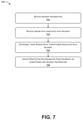
- FIGS. 5-7 illustrate flow charts depicting example processes 500 , 600 , 700 of the present disclosure, and related to triggering incident intervention.
- the example processes 500 , 600 , 700 are illustrated as a collection of steps in a logical flow diagram, which steps represent operations that can be implemented in hardware, software, or a combination thereof.
- the steps represent computer-executable instructions stored in memory.
- the controller processor(s) 404 may cause the controller processor(s) 404 , various components of the computing device(s) 402 , the computing device(s) 424 , the machines 104 and/or the communication device(s) 108 , 112 to perform the recited operations.
- Such computer-executable instructions may include routines, programs, objects, components, data structures, and the like that perform particular functions or implement particular abstract data types.
- the order in which the operations are described is not intended to be construed as a limitation, and any number of the described steps can be combined in any order and/or in parallel to implement the process.
- the processes 500 , 600 , 700 are described with reference to the worksite 100 , the GUIs 200 , 300 , the computing system 400 , and/or other items shown in FIGS. 1-4 .
- the process 500 is illustrated in FIG. 5 and generally describes a method of intervening in incidents.
- the process 500 includes, at 502 , receiving first sensor data indicative of a first condition at a first time and at a location.
- the computing device(s) 402 may receive data, e.g. via one or more signals, from one or more sensing devices, which may include the sensing device(s) 110 associated with one or more of the machines 104 , the sensing device(s) 114 associated with one or more of the personnel 106 at the worksite 100 , and/or the other sensing device(s) 116 located at the worksite 100 .
- the data received at 502 may include position information (e.g., GPS coordinates, map information, a location name, and/or other information from which a position can be determined) indicating a location associated with the sensor data.
- the sensor data may also include a timestamp indicating a time (e.g., day, month, year, hour, minute, second, millisecond, etc.) at which the sensor data was generated by the corresponding sensor(s).
- the sensor data may be directly indicative of the event. For example, sensor data received from a temperature sensor may directly indicate the temperature.
- GPS or other position data from a position sensor on a machine 104 or personnel 106 may sufficiently identify the presence of the machine or the person at the location.
- the sensor data may be used to determine a condition at the worksite 100 .
- the sensor data may also include video and/or image data, e.g., captured by a camera, LIDAR data, RADAR data, and/or other types of data that may be processed to determine the presence of an object and/or the location of the object.
- the image data may be processed, e.g., using facial recognition techniques, to determine an identity of the detected person, to determine the condition.
- Other sensor data may also be received at 502 and used to determine condition(s), e.g., using the data processing/condition recognition system 410 , detailed above in connection with FIG. 4 .
- the process 500 may also include, at 504 , receiving second sensor data indicative of a second condition proximate the location at the first time.
- the computing device(s) 402 may receive data, e.g. via one or more signals, from one or more sensing devices, which may include the sensing device(s) 110 associated with one or more of the machines 104 , the sensing device(s) 114 associated with one or more of the personnel 106 at the worksite 100 , and/or the other sensing device(s) 116 located at the worksite 100 .
- the second sensor data may be received from the same or one or different sensors than the first sensor data received at 502 .
- the second condition may be determined directly from the second sensor data, or determined based at least in part on the second sensor data, e.g., using the data processing/condition recognition system for 10 detailed above.
- the process 500 may also include, at 506 , determining a risk factor associated with the location at the first time.
- the risk factor may be determined, e.g., quantified, based on the first and second conditions.
- the risk factor may be determined using the risk assessment system 412 and/or the risk assessment component 430 .
- the risk factor may be a numerical risk factor, e.g., a number in a predetermined range, e.g., 0-10, 0-100, or the like.
- the risk factor may be a risk level, e.g., high, medium, or low. In still other implementations, the risk factor may be otherwise determined.
- the process 500 also includes generating a user interface visualizing the risk factor at the location.
- the techniques described herein may generate the graphical user interface 200 which includes the map 202 illustrating risks of a worksite 102 .
- those areas or regions that have a higher risk factor e.g., that may be more likely to experience incident such as an accident, may be readily apparent from the map 206 .
- the map 206 may be a heat map with relatively quote hotter” areas indicating high-risk areas and relatively quote cooler” areas representing less likelihood of an incident.
- the graphical user interface 200 may also include user interface elements 214 , 216 , 218 , via which a user, such as a supervisor or the like, reviewing the map 206 may obtain additional information about, and/or act on, those regions that have higher risk factors.
- the process 500 also includes, at 510 , determining whether the risk factors indicative of an actionable event. For example, the techniques described herein may determine whether a risk factor associated with the location has a value that is equal to or above a threshold value. In other examples of this disclosure, it may be determined that the risk factor is indicative of an actionable event upon a user interaction with the user interface generated at 508 . As detailed above in connection with FIG. 3 , the graphical user interface 300 may include user interface elements that allow one or more actions to be taken to mitigate conditions and/or events.
- the process includes, at 512 , determining a corrective action.
- the techniques described herein may determine that the risk may be mitigated by overriding controls of a machine at the location, e.g., to shut the machine down, by contacting personnel 106 proximate the location, e.g., to instruct the personnel to take corrective action, to limit machine capabilities proximate the location, e.g. by creating a safety region around a first machine and controlling the first machine to stay within the safety region and/or controlling other machines to refrain from entering the safety region.
- a number of different corrective actions may be taken to mitigate risks associated with the determined events. Such actions may be dependent on the type of the worksite 100 , e.g., mining versus factory, the potential damage associated with the risk factor, e.g., harm to humans versus machines or the worksite, or other factors.
- the process also includes, at 514 , transmitting information indicative of the corrective action.
- the computing device(s) 402 may send the signal, e.g., via the communication connections 420 , to override or otherwise take control of the machines 104 .
- the action may include transmitting a message, such as a text-based, or audio-based message to a device associated with a machine for, e.g., a speaker in a cab of the machine 104 , or associated with personnel, such as via a radio or other electronic device.
- the process 500 may include, at 516 , after a predetermined time, determining a continued presence of the first condition and the second condition. For example, sensor data like the first sensor data and/or the second sensor data, may continue to be received after the first time and such additional data may continue to be processed and or monitored to determine that the first condition and the second condition persist.
- the process 500 may also include, at 518 , incrementally increasing the risk factor. For example, in implementations of this disclosure, should an elevated risk factor be allowed to persist, a value associated with the risk factor may be increased over time. Thus, for example, should a supervisor or other person overseeing the worksite continue to ignore potentially problematic situation, e.g., as indicated by a plurality of conditions occurring at the same time and place, a value of a risk factor associated with that situation may continue to be increased. From 518 , the process may return to 510 , at which it is determined whether the risk factor is indicative of an actionable event. As will be appreciated and, as the potentially problematic situation continues to go ignored, a risk factor associated with the situation will increase, until eventually the process 500 will take action to mitigate the risk.
- FIG. 6 illustrates the process 600 .
- the process 600 may describe techniques for generating and updating a user interface, such as the GUIs 200 , 300 that allow a user, such as a supervisor or the like, to monitor a worksite, such as the worksite 100 , and selectively intervene to mitigate risks.
- the process 600 includes determining multiple regions of the worksite 100 .
- the techniques described herein may determine the regions 212 illustrated in FIG. 2 .
- Each of the regions 212 may have a similar or the same surface area.
- the size of each of the regions 212 may be determined by the size of the worksite.
- the number of regions 212 may be predetermined regardless of the size of the worksite, in which case the regions will be relatively larger for a relatively smaller work site and relatively smaller for a larger worksite.
- the size of the regions may be dynamically adjusted, e.g., according to a number of objects detected in a region. Using the worksite 100 as an example, more and/or smaller regions may be determined in and/or proximate the open-pit mine 102 whereas fewer and/or larger regions may be used at or about a periphery of the worksite 100 .
- the process 600 may also include, at 604 , receiving sensor information indicative of a plurality of conditions at the worksite.
- the sensor information received at 604 may be from any of the sensing devices 110 associated with the machines 104 , the sensing devices 114 associated with the personnel 106 , the additional sensing devices 116 , and/or the sensor systems 432 .
- the sensor information received at 604 may be the same as the first sensor data and/or the second sensor data received at 502 and 504 , respectively. Sensor modalities and types of sensor data are discussed throughout this disclosure.
- the process 600 may also include, at 606 , determining from the plurality of conditions, conditions associated with each of the multiple regions. For example, location data for each of the plurality of conditions may be determined based on locations of the sensors, via image processing techniques, and/or in other ways.
- the process 600 may also include, at 608 , determining, for each of the multiple regions, a risk factor based on the condition(s).
- a risk factor may be determined, e.g., quantified, for each region, based on the conditions existing in that region.
- the risk factor may be determined using the risk assessment system 412 and/or the risk assessment component 430 .
- the risk factor may have a numerical value, e.g., a number in a predetermined range, e.g., 0-10, 0-100, or the like.
- the risk factor may be a risk level, e.g., high, medium, or low.
- the risk factor may be otherwise quantified.
- the process 600 may also include, at 610 , generating a user interface including graphical representation of the worksite and visual indicators of the risk factors at the regions.
- the techniques described herein may generate the map 202 on the GUI 200 illustrated in FIG. 2 .
- each of the regions e.g., the regions determined at 602
- the user interface may provide a user, such as a supervisor of the worksite 100 , a graphical illustration of the worksite as well as risks associated with the site at any given time.
- the graphical user interface may be updated in real time, or in near-real time, to keep the supervisor up to date at all times about the goings-on at the worksite 100 and to provide the supervisor with tools to investigate aspects of the worksite in more detail.
- the process 600 may also include, at 612 , receiving, via the user interface, selection of a region.
- the supervisor described may desire to receive additional information about a region indicated as having a relatively higher risk factor.
- the user may select a region of interest by selecting the region on the map 202 , by selecting one of the user interface elements 214 , 216 , 218 corresponding to a region, and/or by selecting a graphical indicator, such as the designation 220 , associated with the region or with the risk factor.
- the process 600 may also include, at 614 , updating the user interface to include additional information about the region.
- This additional information may include information about the conditions, about corrective actions for mitigating risk at the region, or the like.
- FIG. 3 illustrates a GUI 300 displayed in response to a user selection of a user interface element associated with the event A.
- the additional information may include a first portion 304 that includes information about the conditions present in the region, and the additional information may also include a second portion 308 that provides recommended actions for mitigating the risk, and/or provides interactive controls, such as the user interface elements 310 , 312 , 314 for taking action relative to the conditions.
- FIG. 7 illustrates the process 700 .
- the process 700 may illustrate techniques for determining a risk factor determination function.
- the process 700 may be used to determine groups of conditions, e.g., indicators, that may signal an event.
- Techniques described herein use sensor data from multiple sensors to determine conditions, and based on the proximity in time and location of those conditions, determine a risk value for regions of a worksite.
- the risk value may be based on a risk assessment model, e.g., executed by the risk assessment system 412 , and the risk assessment model may be informed by incidents, e.g., accidents at the worksite.
- the process 700 may include, at 702 , receiving incident information.
- incident information For example, information about a reported incident, e.g., an accident, injury, machine failure, or the like may be input to the computing device(s) 402 .
- a supervisor, a foreman or other personnel may input information about an incident including a time, location, and outcome, e.g., resulting damage, injuries, or the like, pertaining to the incident.
- the process may also include, at 704 , receiving sensor data associated with the incident.
- a time and a location associated with the incident may be known, e.g., from an incident report, and data from one or more sensors, including but not limited to the sensing device(s) 110 associated with the machines 104 , the sensing devices 114 associated with the personnel 106 , the additional sensing device(s) 116 , and/or the sensor system(s) 432 may be retrieved for the time and/or location of the incident.
- the sensor data may be data captured for a period of time before the incident, e.g., seconds, minutes, or hours before the incident.
- the process 700 may also include, at 706 , determining conditions associated with the incident.
- the data processing/condition recognition system 410 may process the sensor data received at 704 to determine one or more conditions at the location of the incident contemporaneously with, or preceding, the incident. Accordingly, at 706 , the process 700 may determine the status of the location leading up to the incident.
- the process 700 may also include, at 708 , updating a risk factor determination function based at least in part on the condition(s) and/or the incident information.
- information about an incident e.g., information about conditions in place at the location of the information, may be used to train the risk assessment system 412 and/or the risk assessment component 430 .
- determining the risk factor may be done using a machine-learned model trained on information about prior incidents.
- the model may be updated.
- an incident e.g., an accident, machine failure, or the like may occur in a different region; perhaps a region that was not indicated as having a high risk factor.
- the process 700 may use information about such an incident to train the model further, e.g., such that the conditions present at the time of or leading up to the time of the incident may result in a higher risk factor when later identified as occurring simultaneously.
- the present disclosure provides systems and methods for identifying conditions affecting a worksite 100 , and taking actions to mitigate risks, e.g., by controlling machines 104 and/or personnel 106 .
- Such systems and methods may be used to more efficiently coordinate activities of the machines 104 and/or the personnel 106 during operations at the worksite 100 .
- such systems and methods may enable a computing system 120 to determine attributes of the worksite 100 with greater confidence and maintain incident-free operation at the worksite.
- the computing system may coordinate operations to be performed with improved accuracy, and thus, may maximize efficiency at the worksite 100 .
- such systems and methods may be used to more accurately manage the operation of the machines at the worksite 100 , thereby reducing operating costs.
- example processing of identifying risks at a worksite 100 may include receiving sensor data from one or more sensing devices 110 , 114 , 116 .
- the sensor data may provide information about a condition at a location of the worksite, e.g., an ambient temperature, a position of a machine 104 or of personnel 106 , the status of safety equipment associated with the machine 104 and/or the personnel 106 .
- the techniques described herein may determine multiple conditions within close proximity of each other, e.g., with a region 212 , of the worksite 100 .
- the region 212 may be a predetermined area of the worksite 100 . Based on the conditions determined for the region, a risk factor or risk score may be determined for the region.
- the risk factor may be determined by a model, such as a machine-learning model trained on information about previous incidents.
- the process may also include taking one or more actions to mitigate one or more of the conditions, thereby reducing the risk factor.
- techniques described herein may cause the computing system 120 to control a machine 104 to shut down when a value of the risk factor is equal to or exceeds a threshold.
- the computing system 120 may transmit a message or the like to personnel 106 at the worksite, with instructions for mitigating the risk.
- a graphical user interface 200 , 300 may include a map 202 of the worksite 100 .
- the map 202 may include visual indicia of the risk factors.
- the risk factors may be
Landscapes
- Business, Economics & Management (AREA)
- Human Resources & Organizations (AREA)
- Engineering & Computer Science (AREA)
- Strategic Management (AREA)
- Economics (AREA)
- Physics & Mathematics (AREA)
- General Physics & Mathematics (AREA)
- Entrepreneurship & Innovation (AREA)
- Operations Research (AREA)
- General Business, Economics & Management (AREA)
- Development Economics (AREA)
- Game Theory and Decision Science (AREA)
- Theoretical Computer Science (AREA)
- Marketing (AREA)
- Educational Administration (AREA)
- Quality & Reliability (AREA)
- Tourism & Hospitality (AREA)
- General Engineering & Computer Science (AREA)
- Signal Processing (AREA)
- Computer Networks & Wireless Communication (AREA)
- Mechanical Engineering (AREA)
- Mining & Mineral Resources (AREA)
- Civil Engineering (AREA)
- Structural Engineering (AREA)
- User Interface Of Digital Computer (AREA)
Abstract
Description
Claims (20)
Priority Applications (2)
| Application Number | Priority Date | Filing Date | Title |
|---|---|---|---|
| US16/115,108 US11227242B2 (en) | 2018-08-28 | 2018-08-28 | System and method for automatically triggering incident intervention |
| PCT/US2019/046730 WO2020046598A1 (en) | 2018-08-28 | 2019-08-16 | System and method for automatically triggering incident intervention |
Applications Claiming Priority (1)
| Application Number | Priority Date | Filing Date | Title |
|---|---|---|---|
| US16/115,108 US11227242B2 (en) | 2018-08-28 | 2018-08-28 | System and method for automatically triggering incident intervention |
Publications (2)
| Publication Number | Publication Date |
|---|---|
| US20200074383A1 US20200074383A1 (en) | 2020-03-05 |
| US11227242B2 true US11227242B2 (en) | 2022-01-18 |
Family
ID=67841163
Family Applications (1)
| Application Number | Title | Priority Date | Filing Date |
|---|---|---|---|
| US16/115,108 Active 2039-01-16 US11227242B2 (en) | 2018-08-28 | 2018-08-28 | System and method for automatically triggering incident intervention |
Country Status (2)
| Country | Link |
|---|---|
| US (1) | US11227242B2 (en) |
| WO (1) | WO2020046598A1 (en) |
Families Citing this family (24)
| Publication number | Priority date | Publication date | Assignee | Title |
|---|---|---|---|---|
| US12014304B2 (en) * | 2018-01-29 | 2024-06-18 | Procore Technologies, Inc. | Identifying and monitoring productivity, health, and safety risks in industrial sites |
| US11301683B2 (en) * | 2018-10-10 | 2022-04-12 | Autodesk, Inc. | Architecture, engineering and construction (AEC) construction safety risk analysis system and method for interactive visualization and capture |
| KR102090409B1 (en) * | 2018-12-27 | 2020-03-17 | 한양대학교 에리카산학협력단 | Apparatus and method of controlling a remote-controlled excavator for preventing overload |
| US12204294B2 (en) * | 2019-04-11 | 2025-01-21 | Kyndryl, Inc. | Auto-adjustable machine functionality using analytics of sensor data |
| EP3731201B1 (en) * | 2019-04-24 | 2022-11-09 | ABB Schweiz AG | A support system for an operator |
| US11787413B2 (en) | 2019-04-26 | 2023-10-17 | Samsara Inc. | Baseline event detection system |
| US10999374B2 (en) | 2019-04-26 | 2021-05-04 | Samsara Inc. | Event detection system |
| US11195402B2 (en) * | 2019-07-25 | 2021-12-07 | International Business Machines Corporation | Predictive warning system |
| JP7112758B2 (en) * | 2020-03-19 | 2022-08-04 | Totalmasters株式会社 | Construction site safety control device |
| WO2021193450A1 (en) * | 2020-03-25 | 2021-09-30 | 住友重機械工業株式会社 | Construction machine, management system for construction machine, machine learning device, and management system for work site of construction machine |
| US12230138B2 (en) * | 2020-06-30 | 2025-02-18 | Sandvik Mining And Construction Oy | Mine collision detection and avoidance |
| EP3933530B1 (en) * | 2020-06-30 | 2025-06-18 | Sandvik Mining and Construction Oy | Collision detection and avoidance inside a mine |
| CN115769163A (en) * | 2020-06-30 | 2023-03-07 | 山特维克矿山工程机械有限公司 | Collision detection and avoidance inside a mine |
| US11704615B2 (en) * | 2020-08-31 | 2023-07-18 | altumAI Insurance Solutions, LLC | Risk assessment apparatus and related methods |
| EP4224452A4 (en) * | 2020-09-29 | 2024-03-06 | Sony Semiconductor Solutions Corporation | INFORMATION PROCESSING SYSTEM AND INFORMATION PROCESSING METHOD |
| CN112329540A (en) * | 2020-10-10 | 2021-02-05 | 广西电网有限责任公司电力科学研究院 | An identification method and system for monitoring in-position operation of overhead transmission lines |
| JP7548773B2 (en) * | 2020-10-27 | 2024-09-10 | 株式会社小松製作所 | Safety assessment system and safety assessment method |
| AU2021409557A1 (en) | 2020-12-21 | 2023-08-10 | Procore Technologies, Inc. | Identifying and monitoring productivity, health, and safety risks in industrial sites |
| US12307549B2 (en) * | 2021-03-08 | 2025-05-20 | International Business Machines Corporation | Surrounding assessment for heat map visualization |
| US11609688B2 (en) * | 2021-05-25 | 2023-03-21 | Caterpillar Inc. | Systems and methods for managing on-site machines by spatial and contextual information |
| US20230186224A1 (en) * | 2021-12-13 | 2023-06-15 | Accenture Global Solutions Limited | Systems and methods for analyzing and optimizing worker performance |
| CN114434200A (en) * | 2021-12-27 | 2022-05-06 | 重庆长安新能源汽车科技有限公司 | High-safety-risk mechanical equipment safety protection method and system |
| US20230394605A1 (en) * | 2022-06-06 | 2023-12-07 | Procore Technologies, Inc. | Construction Project Risk Assessment and Mitigation |
| CN119740179B (en) * | 2025-03-04 | 2025-07-11 | 中国铁塔股份有限公司浙江省分公司 | Railway tunnel environment monitoring system and method based on Internet of things |
Citations (15)
| Publication number | Priority date | Publication date | Assignee | Title |
|---|---|---|---|---|
| US20140184643A1 (en) | 2012-12-27 | 2014-07-03 | Caterpillar Inc. | Augmented Reality Worksite |
| US20150343947A1 (en) * | 2014-05-30 | 2015-12-03 | State Farm Mutual Automobile Insurance Company | Systems and Methods for Determining a Vehicle is at an Elevated Risk for an Animal Collision |
| US20160257310A1 (en) | 2015-03-07 | 2016-09-08 | Caterpillar Inc. | System and method for worksite operation optimization based on operator conditions |
| WO2016160896A1 (en) | 2015-04-01 | 2016-10-06 | Caterpillar Inc. | Time-shift controlled visualization of worksite operations |
| US9466038B2 (en) * | 2014-02-21 | 2016-10-11 | Safety Key Solutions FZ-LLC | Worksite monitoring and management systems and platforms |
| US20170132884A1 (en) * | 2015-11-09 | 2017-05-11 | Honeywell International Inc. | Aggregate Monitor Data in Real-Time by Worker |
| US20170147958A1 (en) * | 2015-11-20 | 2017-05-25 | Caterpillar Inc. | System and method for connecting an operator with worksite operations |
| US20170193379A1 (en) * | 2015-12-30 | 2017-07-06 | International Business Machines Corporation | Predictive alerts for individual risk of injury with ameliorative actions |
| US20170193787A1 (en) | 2015-10-30 | 2017-07-06 | Blue Willow Systems, Inc. | Methods for detecting and handling fall and perimeter breach events for residents of an assisted living facility |
| US20170248949A1 (en) * | 2015-05-27 | 2017-08-31 | Dov Moran | Alerting predicted accidents between driverless cars |
| US20170254050A1 (en) | 2016-03-03 | 2017-09-07 | Caterpillar Inc. | System and method for operating implement system of machine |
| WO2017201053A1 (en) | 2016-05-16 | 2017-11-23 | Illumagear, Inc. | Configurable user tracking and site safety |
| US20170352242A1 (en) * | 2016-06-06 | 2017-12-07 | Makusafe Corp. | Safety device, system and method of use |
| US20200004938A1 (en) * | 2016-06-10 | 2020-01-02 | OneTrust, LLC | Data processing and scanning systems for assessing vendor risk |
| US20200273268A1 (en) * | 2016-09-13 | 2020-08-27 | Iocurrents, Inc. | System and method for interfacing with a vehicular controller area network |
-
2018
- 2018-08-28 US US16/115,108 patent/US11227242B2/en active Active
-
2019
- 2019-08-16 WO PCT/US2019/046730 patent/WO2020046598A1/en not_active Ceased
Patent Citations (15)
| Publication number | Priority date | Publication date | Assignee | Title |
|---|---|---|---|---|
| US20140184643A1 (en) | 2012-12-27 | 2014-07-03 | Caterpillar Inc. | Augmented Reality Worksite |
| US9466038B2 (en) * | 2014-02-21 | 2016-10-11 | Safety Key Solutions FZ-LLC | Worksite monitoring and management systems and platforms |
| US20150343947A1 (en) * | 2014-05-30 | 2015-12-03 | State Farm Mutual Automobile Insurance Company | Systems and Methods for Determining a Vehicle is at an Elevated Risk for an Animal Collision |
| US20160257310A1 (en) | 2015-03-07 | 2016-09-08 | Caterpillar Inc. | System and method for worksite operation optimization based on operator conditions |
| WO2016160896A1 (en) | 2015-04-01 | 2016-10-06 | Caterpillar Inc. | Time-shift controlled visualization of worksite operations |
| US20170248949A1 (en) * | 2015-05-27 | 2017-08-31 | Dov Moran | Alerting predicted accidents between driverless cars |
| US20170193787A1 (en) | 2015-10-30 | 2017-07-06 | Blue Willow Systems, Inc. | Methods for detecting and handling fall and perimeter breach events for residents of an assisted living facility |
| US20170132884A1 (en) * | 2015-11-09 | 2017-05-11 | Honeywell International Inc. | Aggregate Monitor Data in Real-Time by Worker |
| US20170147958A1 (en) * | 2015-11-20 | 2017-05-25 | Caterpillar Inc. | System and method for connecting an operator with worksite operations |
| US20170193379A1 (en) * | 2015-12-30 | 2017-07-06 | International Business Machines Corporation | Predictive alerts for individual risk of injury with ameliorative actions |
| US20170254050A1 (en) | 2016-03-03 | 2017-09-07 | Caterpillar Inc. | System and method for operating implement system of machine |
| WO2017201053A1 (en) | 2016-05-16 | 2017-11-23 | Illumagear, Inc. | Configurable user tracking and site safety |
| US20170352242A1 (en) * | 2016-06-06 | 2017-12-07 | Makusafe Corp. | Safety device, system and method of use |
| US20200004938A1 (en) * | 2016-06-10 | 2020-01-02 | OneTrust, LLC | Data processing and scanning systems for assessing vendor risk |
| US20200273268A1 (en) * | 2016-09-13 | 2020-08-27 | Iocurrents, Inc. | System and method for interfacing with a vehicular controller area network |
Also Published As
| Publication number | Publication date |
|---|---|
| WO2020046598A1 (en) | 2020-03-05 |
| US20200074383A1 (en) | 2020-03-05 |
Similar Documents
| Publication | Publication Date | Title |
|---|---|---|
| US11227242B2 (en) | System and method for automatically triggering incident intervention | |
| KR102454612B1 (en) | Safety management system for construction machinery, management device | |
| US12394520B2 (en) | Systems and methods for operations and incident management | |
| KR102911293B1 (en) | Shovel and construction system | |
| EP4058956B1 (en) | System for validating worksites | |
| US11216664B2 (en) | Method and device for augmenting a person's view of a mining vehicle on a mining worksite in real-time | |
| US11157849B2 (en) | Construction management method based on a current landform and a design landform of a construction site | |
| Riaz et al. | SightSafety: A hybrid information and communication technology system for reducing vehicle/pedestrian collisions | |
| US20180357583A1 (en) | Operational monitoring system | |
| US20170147958A1 (en) | System and method for connecting an operator with worksite operations | |
| Wang et al. | Two 4D models effective in reducing false alarms for struck-by-equipment hazard prevention | |
| US10671948B2 (en) | Work cycle management | |
| US9582979B2 (en) | Improving safety on sites with movable objects | |
| CN119763296A (en) | Security warning method, device, equipment, storage medium and computer program product | |
| US11423781B2 (en) | System and method for facilitating coordinated, efficient response to fire emergency | |
| Marks | Active safety leading indicators for human-equipment interaction on construction sites | |
| Laurini et al. | Safety monitoring by means of sensor networks distributed within the fossa site plan | |
| US20210042676A1 (en) | System for communicating between assets on a construction site and a database server | |
| KR20250100574A (en) | System and method for ensuring safety through mobile management of construction site risk factors | |
| JP2024120608A (en) | Accident prediction system, accident prediction device, accident prediction method, and program | |
| Rashid | Coupling Mobile Technology, Position Data Mining, and Attitude toward Risk to Improve Construction Site Safety |
Legal Events
| Date | Code | Title | Description |
|---|---|---|---|
| AS | Assignment |
Owner name: CATERPILLAR INC., ILLINOIS Free format text: ASSIGNMENT OF ASSIGNORS INTEREST;ASSIGNORS:SMITH, NIGEL GRAHAM;BEGNER, ELISA BETH;EDWARDS, DAVID JAMES;AND OTHERS;SIGNING DATES FROM 20180827 TO 20180828;REEL/FRAME:046729/0317 |
|
| FEPP | Fee payment procedure |
Free format text: ENTITY STATUS SET TO UNDISCOUNTED (ORIGINAL EVENT CODE: BIG.); ENTITY STATUS OF PATENT OWNER: LARGE ENTITY |
|
| STPP | Information on status: patent application and granting procedure in general |
Free format text: RESPONSE TO NON-FINAL OFFICE ACTION ENTERED AND FORWARDED TO EXAMINER |
|
| STPP | Information on status: patent application and granting procedure in general |
Free format text: ADVISORY ACTION MAILED |
|
| STPP | Information on status: patent application and granting procedure in general |
Free format text: NON FINAL ACTION MAILED |
|
| STPP | Information on status: patent application and granting procedure in general |
Free format text: RESPONSE TO NON-FINAL OFFICE ACTION ENTERED AND FORWARDED TO EXAMINER |
|
| STPP | Information on status: patent application and granting procedure in general |
Free format text: NOTICE OF ALLOWANCE MAILED -- APPLICATION RECEIVED IN OFFICE OF PUBLICATIONS |
|
| STPP | Information on status: patent application and granting procedure in general |
Free format text: PUBLICATIONS -- ISSUE FEE PAYMENT VERIFIED |
|
| STCF | Information on status: patent grant |
Free format text: PATENTED CASE |
|
| MAFP | Maintenance fee payment |
Free format text: PAYMENT OF MAINTENANCE FEE, 4TH YEAR, LARGE ENTITY (ORIGINAL EVENT CODE: M1551); ENTITY STATUS OF PATENT OWNER: LARGE ENTITY Year of fee payment: 4 |