US11226010B2 - Flexible sleeve coupling radial tooth support cap and method - Google Patents
Flexible sleeve coupling radial tooth support cap and method Download PDFInfo
- Publication number
- US11226010B2 US11226010B2 US16/267,685 US201916267685A US11226010B2 US 11226010 B2 US11226010 B2 US 11226010B2 US 201916267685 A US201916267685 A US 201916267685A US 11226010 B2 US11226010 B2 US 11226010B2
- Authority
- US
- United States
- Prior art keywords
- flexible sleeve
- dowels
- flexible
- teeth
- plate
- Prior art date
- Legal status (The legal status is an assumption and is not a legal conclusion. Google has not performed a legal analysis and makes no representation as to the accuracy of the status listed.)
- Active, expires
Links
Images


Classifications
-
- F—MECHANICAL ENGINEERING; LIGHTING; HEATING; WEAPONS; BLASTING
- F16—ENGINEERING ELEMENTS AND UNITS; GENERAL MEASURES FOR PRODUCING AND MAINTAINING EFFECTIVE FUNCTIONING OF MACHINES OR INSTALLATIONS; THERMAL INSULATION IN GENERAL
- F16D—COUPLINGS FOR TRANSMITTING ROTATION; CLUTCHES; BRAKES
- F16D3/00—Yielding couplings, i.e. with means permitting movement between the connected parts during the drive
- F16D3/50—Yielding couplings, i.e. with means permitting movement between the connected parts during the drive with the coupling parts connected by one or more intermediate members
- F16D3/72—Yielding couplings, i.e. with means permitting movement between the connected parts during the drive with the coupling parts connected by one or more intermediate members with axially-spaced attachments to the coupling parts
- F16D3/74—Yielding couplings, i.e. with means permitting movement between the connected parts during the drive with the coupling parts connected by one or more intermediate members with axially-spaced attachments to the coupling parts the intermediate member or members being made of rubber or other rubber-like flexible material
-
- F—MECHANICAL ENGINEERING; LIGHTING; HEATING; WEAPONS; BLASTING
- F16—ENGINEERING ELEMENTS AND UNITS; GENERAL MEASURES FOR PRODUCING AND MAINTAINING EFFECTIVE FUNCTIONING OF MACHINES OR INSTALLATIONS; THERMAL INSULATION IN GENERAL
- F16B—DEVICES FOR FASTENING OR SECURING CONSTRUCTIONAL ELEMENTS OR MACHINE PARTS TOGETHER, e.g. NAILS, BOLTS, CIRCLIPS, CLAMPS, CLIPS OR WEDGES; JOINTS OR JOINTING
- F16B11/00—Connecting constructional elements or machine parts by sticking or pressing them together, e.g. cold pressure welding
- F16B11/006—Connecting constructional elements or machine parts by sticking or pressing them together, e.g. cold pressure welding by gluing
- F16B11/008—Connecting constructional elements or machine parts by sticking or pressing them together, e.g. cold pressure welding by gluing of tubular elements or rods in coaxial engagement
-
- Y—GENERAL TAGGING OF NEW TECHNOLOGICAL DEVELOPMENTS; GENERAL TAGGING OF CROSS-SECTIONAL TECHNOLOGIES SPANNING OVER SEVERAL SECTIONS OF THE IPC; TECHNICAL SUBJECTS COVERED BY FORMER USPC CROSS-REFERENCE ART COLLECTIONS [XRACs] AND DIGESTS
- Y10—TECHNICAL SUBJECTS COVERED BY FORMER USPC
- Y10T—TECHNICAL SUBJECTS COVERED BY FORMER US CLASSIFICATION
- Y10T403/00—Joints and connections
- Y10T403/45—Flexibly connected rigid members
- Y10T403/453—Flexible sleeve-type coupling
-
- Y—GENERAL TAGGING OF NEW TECHNOLOGICAL DEVELOPMENTS; GENERAL TAGGING OF CROSS-SECTIONAL TECHNOLOGIES SPANNING OVER SEVERAL SECTIONS OF THE IPC; TECHNICAL SUBJECTS COVERED BY FORMER USPC CROSS-REFERENCE ART COLLECTIONS [XRACs] AND DIGESTS
- Y10—TECHNICAL SUBJECTS COVERED BY FORMER USPC
- Y10T—TECHNICAL SUBJECTS COVERED BY FORMER US CLASSIFICATION
- Y10T403/00—Joints and connections
- Y10T403/70—Interfitted members
- Y10T403/7026—Longitudinally splined or fluted rod
Definitions
- the present disclosure relates to power transmission and, more particularly, to mechanical power transmission using flexible or yielding couplings.
- Elastomeric couplings for connecting driving and driven mechanical components, typically in the form of rotating shafts are known. Elastomeric couplings are uniquely suited for use in applications where shock, vibration and misalignment may be present.
- driving and driven metal or otherwise stiff hubs are connected on either side of a transmission junction and are connected to one another using an elastomeric or yielding material such as EPDM, Neoprene, Hytrel® and the like.
- EPDM elastomeric or yielding material
- Neoprene Neoprene
- Hytrel® Hytrel®
- the present disclosure describes flexible coupling.
- the flexible coupling includes two hubs, each hub configured to engage a shaft along a central portion and engage flexible sleeve along an engagement portion.
- the flexible coupling further includes a flexible member assembly disposed between the two hubs in engaged relation between the engagement portions of each of the two hubs.
- the flexible member assembly includes a flexible sleeve having a first end and a second end, a first stiffening cap attached to the first end of the flexible sleeve between the flexible sleeve and the engagement portion of one of the two hubs, and a second stiffening cap attached to the second end of the flexible sleeve between the flexible sleeve and the engagement portion of the other of the two hubs.
- the present disclosure describes a flexible sleeve for use with a flexible coupling.
- the flexible coupling includes two hubs, each hub configured to engage a shaft along a central portion and engage the flexible sleeve along an engagement portion.
- the flexible sleeve further includes a first plurality of dowels attached to a first end of the flexible sleeve.
- the first plurality of dowels is adapted to be disposed between the flexible sleeve and the engagement portion of one of the two hubs of the flexible coupling.
- the flexible sleeve also includes a second plurality of dowels attached to a second end of the flexible sleeve.
- the second plurality of dowels is adapted to be disposed between the flexible sleeve and the engagement portion of the other of the two hubs.
- the disclosure describes a method for increasing a tooth shear strength without also increasing a torsional rigidity of a flexible sleeve disposed between two hubs of a flexible coupling for transmitting mechanical motion between two shafts.
- the method includes attaching a first stiffening cap to a first end of the flexible sleeve between the flexible sleeve and an engagement portion of one of the two hubs, and attaching a second stiffening cap to a second end of the flexible sleeve between the flexible sleeve and the engagement portion of the other of the two hubs.
- FIG. 1 is an outline view of a flexible sleeve coupling in accordance with the disclosure.
- FIG. 2 is an exploded view of a flexible sleeve coupling in accordance with the disclosure.
- FIG. 3 is an outline view of a flexible sleeve having tooth support elements in accordance with the disclosure.
- FIG. 4 is an outline view of a tooth support cap in accordance with the disclosure.
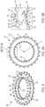
- FIG. 5A is an outline view from a top perspective of a flexible sleeve in accordance with the disclosure
- FIG. 5B is an enlarged detail view of a portion of FIG. 5A .
- FIG. 6 is an outline view of a tooth support cap in accordance with an alternative embodiment.
- FIG. 7A is an outline view from a top perspective of a flexible sleeve in accordance with the alternative embodiment
- FIG. 7B is an enlarged detail view of a portion of FIG. 7A .
- FIG. 8 is a partial view of a flexible sleeve having a tooth support
- FIG. 9 is a view of the tooth support, in accordance with the disclosure.
- FIG. 10 is an outline view of a partial tooth support in accordance with the disclosure.
- FIGS. 11 and 12 are partial section views from different perspectives of an alternative embodiment in accordance with the disclosure.
- the present disclosure is directed to flexible sleeve couplings and, more particularly, to systems and methods for improving the couplings' ability to withstand torque loading variations without compromising their ability to handle misalignment during operation.
- the flexible couplings exhibit an improved resistance to torsional shear without also increasing their torsional rigidity.
- structures are introduced to stiffen each tooth at either end of the coupling sleeve, along both the inner and outer diameters of the sleeve, by inserting and bonding or otherwise attaching a stud or dowel extending through a portion of each tooth, and/or by encapsulating the teeth in boding relation to a liner.
- the studs or liners advantageously support the teeth and prevent excessive deformation, which allows for high torque transmission, without impacting the misalignment capabilities or the torsional stiffness of the sleeve coupling element.
- the increased torque capacity advantageously provides an opportunity to downsize the coupling size for a particular application, which can result in cost savings.
- FIG. 1 An outline view of a coupling 100 in accordance with the disclosure is shown in FIG. 1 in an assembled state, and in an exploded state in FIG. 2 to illustrate certain internal structures thereof.
- the coupling 100 includes two hubs 102 , each having a central portion 104 configured to engage a shaft (not shown) and an engagement portion 106 that is configured to engage toothed ends of a flexible member assembly 108 .
- the engagement portion 106 of each hub 102 includes an inner row of teeth 110 and an outer row of teeth 112 concentrically disposed with one another with respect to a longitudinal axis, L.
- the inner and outer rows of teeth 110 and 112 meshably engage corresponding inner and outer rows of teeth 116 and 114 , respectively, formed at either axial end of a flexible sleeve 118 included in the flexible member assembly 108 .
- the flexible sleeve 118 may have an overall length, M, in the axial direction.
- each hub 102 is installed close to an end of a shaft (not shown) through an axial opening 120 extending through the central portion 104 of the hub 102 .
- spacer hubs may also be used (not shown here) in the known fashion to mount the flexible coupling.
- the axial opening 120 may include a key slot 122 and setscrew 124 disposed in a bore extending through a shoulder portion 126 of the central portion 104 .
- the two shafts onto which the hubs 102 are mounted may be two sides of a drive arrangement, for example, between a driving component such as a motor and a driven component such as a pump, drive shaft, conveyor and the like.
- the torque transmitted through the coupling 100 may include transient disturbances such as torque spikes, vibrations and the like.
- transient effects in the transmitted torque may be absorbed or otherwise dampened by the elastomeric or resilient material from which the flexible sleeve 118 is made.
- the flexible sleeve 118 can also flex and conform to the misalignment between the axes L 1 and L 2 .
- a tooth support cap 200 is used in the embodiment shown in FIG. 2 , and also in FIG. 3 .
- a disassembled view of the flexible sleeve 118 and the tooth support cap 200 is also shown in FIGS. 4 and 5 .
- the tooth support cap 200 includes a plate 202 having a generally annular shape that includes an inner periphery 204 and an outer periphery 206 ( FIG. 4 ).
- a first plurality of dowels 208 is integrally formed or otherwise connected to the plate 202 .
- the first plurality of dowels 208 are connected at one end to the plate 202 and extend symmetrically around the plate adjacent the outer periphery 206 .
- a second plurality of dowels 210 is also integrally formed or otherwise connected to the plate 202 .
- the second plurality of dowels 210 are also connected at one end to the plate and extend symmetrically around the plate adjacent the inner periphery 204 .
- the dowels belonging to the first and second pluralities of dowels 210 and 208 extend parallel to one another and have generally the same length in the exemplary embodiment shown. As can be appreciated, however, the dowels 210 and 208 may have different lengths. For example, the dowels 210 may be longer and extend deeper into the flexible coupling adjacent the inner periphery 204 than the outer dowels 208 . In this embodiment, the dowels have a circular cross section that results in a cylindrical shape for each dowel. The first and second pluralities of dowels 210 and 208 are also connected on the same side of the plate 202 .
- the dowels 208 and 210 are inserted into openings or bores extending through the axial length of the corresponding inner and outer rows of teeth until the plate 202 is flush with an end face of the flexible sleeve 118 .
- the term “dowel” does not indicate a shape for the structures described, which can have circular and non-circular cross sections, as will be described for alternative embodiments later.
- an end face 128 of the flexible sleeve 118 has a generally annular shape defined between an outer periphery 130 and an inner periphery 132 .
- the outer periphery 130 has a jagged shape that forms the outer row of teeth 114 , which in the illustrated embodiment have a generally triangular shape that includes two inclined side faces 134 that meet at a peak 136 to form a convex tooth shape. Crests 138 separate adjacent teeth.
- the inner periphery 132 has a jagged shape that forms the inner row of teeth 116 , which also include inclined side faces 134 alternately disposed with crests 138 and peaks 136 . As shown, the inner and outer teeth 116 and 114 are radially aligned in pairs along any radius, R, extending outwardly from the longitudinal axis.
- each outer tooth 114 forms a bore 212 .
- the bore 212 has a circular cross section. The radial location of the bore 212 is offset from the outer periphery 130 and extends in an axial direction, i.e., parallel to the longitudinal axis L, through the tooth.
- the bore 212 can be placed close to the geometrical center of the tooth 114 such that the inclined faces 134 extend tangentially to the bore 212 but at an offset distance, d 1 , therefrom, and the peak 136 is radially aligned with a centerpoint of the bore 212 .
- each inner tooth 116 forms a bore 214 , which is also circular but at a smaller diameter relative to the bore 212 of each outer tooth 114 .
- each inner tooth 116 The radial location of the bore 212 in each inner tooth 116 is offset from the inner periphery 132 and extends in an axial direction through the corresponding inner tooth 116 .
- the bore 212 is also placed close to or on the geometrical center of the inner tooth 116 such that the inclined faces 134 extend tangentially to the bore 212 but at an offset distance, d 2 , therefrom, and the peak 136 is radially aligned with a centerpoint of the bore 212 .
- the distances d 1 and d 2 are shown to be about the same in the embodiment of FIG. 5 , which means that the bore 212 is formed somewhere along a radially extending centerline of each tooth, but can alternatively be selected to be different, for example, such that d 1 >d 2 or d 2 >d 1 .
- the shape of the plate 202 and, specifically, the inner and outer peripheries 204 and 206 are arranged to match the shape of the inner and outer peripheries 132 and 130 of the flexible sleeve 118 .
- the number and placement of the first plurality of dowels 208 , and also the diameter of each dowels 208 is selected to match the arrangement, placement and size of the bores 212 formed in the outer plurality of teeth 114 .
- the number, placement and size of the second plurality of dowels 210 is selected to match the arrangement, placement and size of the bores 212 formed in the inner periphery of teeth 114 .
- a layer of adhesive 216 may be spread over the face of the plate 202 and also along the lateral surfaces of the first and second pluralities of dowels 208 and 210 before the cap 200 is installed onto the end face 128 .
- the side of the plate 202 from which the dowels 208 and 210 extend is flush or abuts onto the end face 128 , and the dowels 208 and 210 extend through the corresponding teeth 114 and 116 .
- chamfered tips 218 of the dowels 208 and 210 extend past end openings in the outer teeth 114 .
- FIGS. 6 and 7 An alternative embodiment for the flexible sleeve 118 and tooth support cap 200 is shown in FIGS. 6 and 7 .
- structures and features that are the same or similar to corresponding structures and features described previously are denoted and referred to by the same reference numerals as previously used for sake of description.
- the shape of the dowels 208 and 210 is non-circular in cross section. It should be noted that the shape of the dowels is contemplated to have any appropriate shape, for example, triangular as shown here but also other shapes, including but not limited to semi-circular, C-shaped, Y-shaped, T-shaped, X-shaped, I-shaped, V-shaped, star shaped, rectangular, hexagonal, pentagonal, wave-shaped, and others.
- Shape selection may depend on various factors including the desired contact area between the dowels and their bores, the material of the dowels, the material of the flexible sleeve, the amount and type of adhesive used between the dowels and their corresponding bores, the manufacturing method used to construct the cap, and others.
- the cap may be constructed by any sufficiently rigid material including a thermoplastic material, nylon (including glass-filled nylon), metal, fiberglass composites, and the like.
- FIGS. 6 and 7 While various features in the embodiment shown in FIGS. 6 and 7 are similar to the embodiment shown in FIGS. 4 and 5 with respect to the general arrangement of components, it can be seen that here the shape of the dowels 208 and 210 is triangular rather than circular. Consequently, the bores 212 also have a triangular shape that mates with the shape of the dowels 208 and 210 . Because of this difference, a different type of support may be lent by the dowels to the outer and inner peripheries of the flexible sleeve 118 and the end face 128 .
- the triangular dowels 208 and 210 of the embodiment shown in FIGS. 6 and 7 includes an orientation of the dowels in side faces 220 of the dowels 208 and 210 are orientated to be generally parallel with the inclined side faces 134 of the inner and outer teeth 116 and 114 .
- the distances d 1 and d 2 thus denote a layer of flexible material that has a uniform thickness over each side face 220 and provides a more reliable cushioning effect that, in certain applications, may avoid possible pinch points in embodiments with a non-uniform bore wall thickness between the dowel and an exterior surface of the tooth.
- the third face 222 of each dowel 208 or 210 lies generally tangentially relative to the end-face 128 .
- FIGS. 8 and 9 are all variations in the arrangement of structures of the embodiment shown in FIGS. 4 and 5 , but can alternatively be formed as variations of any other embodiment described herein, including the embodiment shown in FIG. 6 .
- the plate 202 in the embodiment of FIG. 4 is generally annular and extends peripherally around the entire circumference of the end face 128
- the plate is reduced to a pie segment that covers one set of teeth 114 and 116 , and includes thereon one set of dowels, i.e. a single dowel from the first and second pluralities of dowels 208 and 210 .
- a plurality of such caps 202 can be assembled in succession around the periphery of the end face 128 of the flexible sleeve 118 , on both axial ends, such that all bores 212 are occupied by a dowel 208 or 210 when the flexible member assembly 108 is complete andt installed within a pair of hubs 102 .
- the plate 202 may be omitted entirely such that individual dowels 208 and 210 may be assembled into corresponding bores 212 in the inner and outer tows of teeth 114 and 116 .
- a set of dowels such as those shown in FIG. 4 or FIG. 6 would be loosely provided and inserted, one dowel into each corresponding bore.
- a range of different spans of the cap 200 can be used anywhere between a single pair of dowels, as shown in FIG. 9 , to a full set of dowels extending around the entire end face, as shown in FIG. 4 .
- the cap 200 is generally half-circle shaped and extends over a span of 180 degrees around the end face.
- the different spans can be used to cover the entire face of a solid flexible coupling, and also alternative types of couplings that are commonly used including a split coupling having a slit on one side, or a fully split coupling having slits on both sides such that the coupling is formed by two semi-cylindrical pieces assembled together to form a full cylindrical coupling.
- the cap as shown in FIG. 10 would thus occupy half the bores 212 and would be mounted adjacent a mating pair cap to occupy and cover the remaining bores. Other span angles may also be used. It is also noted that the inner periphery 132 of the embodiments for the caps 200 shown in FIGS. 9 and 10 may alternatively be formed to be smooth, and the inner row of dowels 210 may be omitted such that the caps may be installed from the opposite direction shown in FIG. 3 to occupy the bores 212 in the outer row of teeth 114 .
- two opposed plates 202 can be connected at least to the outer row or dowels 208 such that both axial faces of the teeth 114 on each side of the flexible sleeve 118 can be faced by the plates 202 .
- FIGS. 11 and 12 An additional embodiment for a cap 300 is shown in FIGS. 11 and 12 in partial cross section.
- the cap 300 which may also include dowels 208 and 210 (not shown), includes an outer peripheral wall 306 and an inner peripheral wall 304 that extend parallel to one another and on the same side away from a plate 302 in the axial direction.
- the plate 302 , and the outer and inner peripheral walls 306 and 304 encapsulate an end portion of the flexible sleeve, including the teeth formed thereon.
- the walls 306 and 308 have a jagged edge in cross section that follows the inner and outer peripheries 130 and 132 of the end face 128 to form the outer surfaces of the inner and outer teeth 116 and 114 .
- the cap 300 reduces or eliminates flexing of the teeth 114 and 116 during use, and may be adhered to the end face 128 and teeth 114 and 116 .
- the cap 300 may be made from a rigid but compliant material such as vinyl, poly-vinyl-chloride (PVC), polyethylene-terephthalate (PET), and/or other thermoplastic or polymer materials, which can facilitate installation of the cap 300 into the engagement portion 106 of the hub 102 .
- a first prototype design designated P1
- P1 included round dowels such as the dowels 208 and 210 shown in FIG. 4 , but without adhesives applied to retain the dowels in the rubber material of each tooth, and also without the plate 202 .
- the dowels were inserted into both sides of the sleeve.
- each tooth on the ID and OD of a sleeve end face were drilled to allow for a dowel to be inserted.
- Various sizes of dowels were inserted into the OD and ID teeth. The steel dowels were only held in place by the press fit between the rubber and dowel.
- each dowel has a cross sectional area size that is about 33% of the cross sectional area size of the corresponding tooth, but it should be appreciated that the cross sectional area size of each tooth that is occupied by a dowel may be selected depending on the type of material used for the flexible sleeve and the dowel, the expected loading on the flexible sleeve, the operating environment and other parameters. For most applications, the ratio of the cross sectional area of the dowel over the area of the tooth can be anywhere between 5 and 50%.
- Torsional stiffness was completed on each of the prototypes by rotating the element to its maximum wind up angle and recording the resultant torque. This was repeated multiple times and the results were averaged to yield a final value.
- shafts were installed on each of the driven and driver chucks of a torsion machine, and a flexible element was placed between driver and driven end flanges to mimic an in-service configuration. A maximum acceptable angular misalignment was also introduced between the two shafts.
- P3 performed better than P2 but did not achieve the same torque ratings as P1. It is theorized that this was most likely due to the reduced stiffness caused by the 3D printing used to manufacture the stiffening cap.
- the bonding between the cap and the rubber material of the sleeve eliminated the separation from the element at high angle of twist. Additionally, the bonded cap of P3 increased the angle at which the element slipped in the flange.
- the additional testing performed on P3 included a dynamic misalignment test, which subjected the sample to twice the normal catalog rating for a sleeve coupling and at normal motor operating speed.
- the test station was intentionally misaligned to a worst case condition for the element. Under these conditions, the P3 prototype lasted substantially longer than the control samples B1 and B2.
- tooth reinforcements have the potential to increase the torque capacity of sleeve coupling elements without impacting the torsional stiffness or the formulation of the base rubber compound.
- these tooth reinforcements could be any material that has a substantially higher durometer/stiffness than the base rubber material. Urethane, plastics, rubber, or other metals could be used. Further consideration should be given in terms of the actual shape of the reinforcement in addition to circular shapes, which were the only shapes tested. A triangular shape that mimics the profile of the tooth, such as the embodiment shown in FIG. 6 , may further provide reinforcement in higher torque situations. Additionally, it is recommended to use a high durometer material to provide improved stiffness.
Landscapes
- Engineering & Computer Science (AREA)
- General Engineering & Computer Science (AREA)
- Mechanical Engineering (AREA)
- Tires In General (AREA)
- Snaps, Bayonet Connections, Set Pins, And Snap Rings (AREA)
Abstract
Description
| TABLE 6 |
| Torsional Stiffness and Tooth Shear Results |
| Percent | |||
| increase over | |||
| Sample | control | ||
| B1 | X | ||
| B2 | X | ||
| P1 | 52.2% | ||
| P2 | 5.8% | ||
| P2 | 33.2% | ||
Claims (17)
Priority Applications (2)
| Application Number | Priority Date | Filing Date | Title |
|---|---|---|---|
| US16/267,685 US11226010B2 (en) | 2019-02-05 | 2019-02-05 | Flexible sleeve coupling radial tooth support cap and method |
| US17/545,504 US12066064B2 (en) | 2019-02-05 | 2021-12-08 | Flexible sleeve coupling radial tooth support cap and method |
Applications Claiming Priority (1)
| Application Number | Priority Date | Filing Date | Title |
|---|---|---|---|
| US16/267,685 US11226010B2 (en) | 2019-02-05 | 2019-02-05 | Flexible sleeve coupling radial tooth support cap and method |
Related Child Applications (1)
| Application Number | Title | Priority Date | Filing Date |
|---|---|---|---|
| US17/545,504 Division US12066064B2 (en) | 2019-02-05 | 2021-12-08 | Flexible sleeve coupling radial tooth support cap and method |
Publications (2)
| Publication Number | Publication Date |
|---|---|
| US20200248754A1 US20200248754A1 (en) | 2020-08-06 |
| US11226010B2 true US11226010B2 (en) | 2022-01-18 |
Family
ID=71837366
Family Applications (2)
| Application Number | Title | Priority Date | Filing Date |
|---|---|---|---|
| US16/267,685 Active 2039-12-02 US11226010B2 (en) | 2019-02-05 | 2019-02-05 | Flexible sleeve coupling radial tooth support cap and method |
| US17/545,504 Active 2039-11-07 US12066064B2 (en) | 2019-02-05 | 2021-12-08 | Flexible sleeve coupling radial tooth support cap and method |
Family Applications After (1)
| Application Number | Title | Priority Date | Filing Date |
|---|---|---|---|
| US17/545,504 Active 2039-11-07 US12066064B2 (en) | 2019-02-05 | 2021-12-08 | Flexible sleeve coupling radial tooth support cap and method |
Country Status (1)
| Country | Link |
|---|---|
| US (2) | US11226010B2 (en) |
Cited By (1)
| Publication number | Priority date | Publication date | Assignee | Title |
|---|---|---|---|---|
| US20210285502A1 (en) * | 2020-03-16 | 2021-09-16 | Abb Schweiz Ag | Flexible Reinforced Radial Spline Coupling and Method |
Families Citing this family (2)
| Publication number | Priority date | Publication date | Assignee | Title |
|---|---|---|---|---|
| CN109790873B (en) * | 2016-10-13 | 2021-08-31 | 日本精工株式会社 | Joints for torque transmission and electric power steering |
| GB2599390A (en) * | 2020-09-30 | 2022-04-06 | Renold Plc | Coupling |
Citations (7)
| Publication number | Priority date | Publication date | Assignee | Title |
|---|---|---|---|---|
| US2172707A (en) * | 1939-09-12 | Resilient coupling | ||
| AT179452B (en) * | 1952-01-10 | 1954-09-10 | Voest Ag | Elastic coupling |
| US2857749A (en) * | 1956-08-14 | 1958-10-28 | Nylo Flex Products Company | Flexible coupling |
| US2867102A (en) | 1956-02-13 | 1959-01-06 | Woods T B Sons Co | Flexible couplings for shafts |
| US2867103A (en) | 1957-04-01 | 1959-01-06 | Woods T B Sons Co | Gripping arrangements for flexible couplings for power transmission shafts |
| US3055195A (en) * | 1961-03-28 | 1962-09-25 | Gordon L Olson | Fabricated flexible coupling |
| US5595541A (en) * | 1993-11-19 | 1997-01-21 | P.I.V. S.A. | Flexible adjustable shaft coupling |
Family Cites Families (2)
| Publication number | Priority date | Publication date | Assignee | Title |
|---|---|---|---|---|
| FR2300258A1 (en) * | 1975-02-06 | 1976-09-03 | Pean Pierre | COUPLING PROCESS OF ORGANS AND COUPLINGS OBTAINED |
| DE3434722A1 (en) * | 1984-09-21 | 1986-04-03 | Hackforth GmbH & Co KG, 4690 Herne | HIGHLY ELASTIC SHAFT COUPLING |
-
2019
- 2019-02-05 US US16/267,685 patent/US11226010B2/en active Active
-
2021
- 2021-12-08 US US17/545,504 patent/US12066064B2/en active Active
Patent Citations (7)
| Publication number | Priority date | Publication date | Assignee | Title |
|---|---|---|---|---|
| US2172707A (en) * | 1939-09-12 | Resilient coupling | ||
| AT179452B (en) * | 1952-01-10 | 1954-09-10 | Voest Ag | Elastic coupling |
| US2867102A (en) | 1956-02-13 | 1959-01-06 | Woods T B Sons Co | Flexible couplings for shafts |
| US2857749A (en) * | 1956-08-14 | 1958-10-28 | Nylo Flex Products Company | Flexible coupling |
| US2867103A (en) | 1957-04-01 | 1959-01-06 | Woods T B Sons Co | Gripping arrangements for flexible couplings for power transmission shafts |
| US3055195A (en) * | 1961-03-28 | 1962-09-25 | Gordon L Olson | Fabricated flexible coupling |
| US5595541A (en) * | 1993-11-19 | 1997-01-21 | P.I.V. S.A. | Flexible adjustable shaft coupling |
Cited By (2)
| Publication number | Priority date | Publication date | Assignee | Title |
|---|---|---|---|---|
| US20210285502A1 (en) * | 2020-03-16 | 2021-09-16 | Abb Schweiz Ag | Flexible Reinforced Radial Spline Coupling and Method |
| US11661973B2 (en) * | 2020-03-16 | 2023-05-30 | Dodge Industrial, Inc. | Flexible reinforced radial spline coupling and method |
Also Published As
| Publication number | Publication date |
|---|---|
| US20220099146A1 (en) | 2022-03-31 |
| US12066064B2 (en) | 2024-08-20 |
| US20200248754A1 (en) | 2020-08-06 |
Similar Documents
| Publication | Publication Date | Title |
|---|---|---|
| US12066064B2 (en) | Flexible sleeve coupling radial tooth support cap and method | |
| US7980956B2 (en) | Sleeve and sleeve-type flexible shaft coupling | |
| US8262485B2 (en) | Vibration damper for a drive train | |
| US6142878A (en) | Flexible coupling with elastomeric belt | |
| EP1469218B1 (en) | Flexible coupling | |
| JP2013517433A (en) | Elastic joint | |
| RU2516919C2 (en) | Coupling with annular body | |
| JP2003042179A (en) | Mounting structure of test shaft to balancer | |
| US4536170A (en) | Elastomeric shear shaft coupling | |
| US20230016830A1 (en) | Coupling | |
| US11661973B2 (en) | Flexible reinforced radial spline coupling and method | |
| US6508714B1 (en) | Split spool type flexible coupling | |
| EP1367278A1 (en) | Compression elastic coupling device | |
| KR102260609B1 (en) | Axial displacement limiting flexible coupling | |
| US20030157987A1 (en) | Shaft couplings with bonded flexible elements | |
| US20230016988A1 (en) | Torque Transmitting Elements for Coupling | |
| EP1433970A1 (en) | Shaft coupling with flexible elements | |
| RU85589U1 (en) | ELASTIC COUPLING | |
| JPS6357923A (en) | Elastic coupling | |
| JP2000027883A (en) | Vehicle drive |
Legal Events
| Date | Code | Title | Description |
|---|---|---|---|
| AS | Assignment |
Owner name: ABB SCHWEIZ AG, SWITZERLAND Free format text: ASSIGNMENT OF ASSIGNORS INTEREST;ASSIGNOR:RUBEL, JAMES R.;REEL/FRAME:048239/0838 Effective date: 20190204 |
|
| FEPP | Fee payment procedure |
Free format text: ENTITY STATUS SET TO UNDISCOUNTED (ORIGINAL EVENT CODE: BIG.); ENTITY STATUS OF PATENT OWNER: LARGE ENTITY |
|
| STPP | Information on status: patent application and granting procedure in general |
Free format text: NON FINAL ACTION MAILED |
|
| STPP | Information on status: patent application and granting procedure in general |
Free format text: RESPONSE TO NON-FINAL OFFICE ACTION ENTERED AND FORWARDED TO EXAMINER |
|
| STPP | Information on status: patent application and granting procedure in general |
Free format text: NOTICE OF ALLOWANCE MAILED -- APPLICATION RECEIVED IN OFFICE OF PUBLICATIONS |
|
| AS | Assignment |
Owner name: DODGE ACQUISITION CO., CONNECTICUT Free format text: ASSIGNMENT OF ASSIGNORS INTEREST;ASSIGNORS:ABB SCHWEIZ AG;ABB MOTORS AND MECHANICAL INC.;ABB ASEA BROWN BOVERI LTD;REEL/FRAME:058001/0201 Effective date: 20211101 |
|
| AS | Assignment |
Owner name: WELLS FARGO BANK, NATIONAL ASSOCIATION, AS COLLATERAL AGENT, COLORADO Free format text: SECURITY INTEREST;ASSIGNOR:DODGE ACQUISITION CO.;REEL/FRAME:058099/0286 Effective date: 20211101 |
|
| STPP | Information on status: patent application and granting procedure in general |
Free format text: PUBLICATIONS -- ISSUE FEE PAYMENT VERIFIED |
|
| STCF | Information on status: patent grant |
Free format text: PATENTED CASE |
|
| AS | Assignment |
Owner name: DODGE INDUSTRIAL, INC., CONNECTICUT Free format text: ASSIGNMENT OF ASSIGNORS INTEREST;ASSIGNORS:ABB SCHWEIZ AG;ABB ASEA BROWN BOVERI LTD;ABB MOTORS AND MECHANICAL INC.;AND OTHERS;SIGNING DATES FROM 20220308 TO 20220322;REEL/FRAME:059859/0375 |
|
| MAFP | Maintenance fee payment |
Free format text: PAYMENT OF MAINTENANCE FEE, 4TH YEAR, LARGE ENTITY (ORIGINAL EVENT CODE: M1551); ENTITY STATUS OF PATENT OWNER: LARGE ENTITY Year of fee payment: 4 |