US11226009B2 - Steering shaft assembly - Google Patents
Steering shaft assembly Download PDFInfo
- Publication number
- US11226009B2 US11226009B2 US16/030,218 US201816030218A US11226009B2 US 11226009 B2 US11226009 B2 US 11226009B2 US 201816030218 A US201816030218 A US 201816030218A US 11226009 B2 US11226009 B2 US 11226009B2
- Authority
- US
- United States
- Prior art keywords
- bore
- axis
- extends
- shaft
- along
- Prior art date
- Legal status (The legal status is an assumption and is not a legal conclusion. Google has not performed a legal analysis and makes no representation as to the accuracy of the status listed.)
- Active, expires
Links
Images


Classifications
-
- F—MECHANICAL ENGINEERING; LIGHTING; HEATING; WEAPONS; BLASTING
- F16—ENGINEERING ELEMENTS AND UNITS; GENERAL MEASURES FOR PRODUCING AND MAINTAINING EFFECTIVE FUNCTIONING OF MACHINES OR INSTALLATIONS; THERMAL INSULATION IN GENERAL
- F16D—COUPLINGS FOR TRANSMITTING ROTATION; CLUTCHES; BRAKES
- F16D3/00—Yielding couplings, i.e. with means permitting movement between the connected parts during the drive
- F16D3/16—Universal joints in which flexibility is produced by means of pivots or sliding or rolling connecting parts
- F16D3/26—Hooke's joints or other joints with an equivalent intermediate member to which each coupling part is pivotally or slidably connected
- F16D3/38—Hooke's joints or other joints with an equivalent intermediate member to which each coupling part is pivotally or slidably connected with a single intermediate member with trunnions or bearings arranged on two axes perpendicular to one another
- F16D3/382—Hooke's joints or other joints with an equivalent intermediate member to which each coupling part is pivotally or slidably connected with a single intermediate member with trunnions or bearings arranged on two axes perpendicular to one another constructional details of other than the intermediate member
- F16D3/387—Fork construction; Mounting of fork on shaft; Adapting shaft for mounting of fork
-
- F—MECHANICAL ENGINEERING; LIGHTING; HEATING; WEAPONS; BLASTING
- F16—ENGINEERING ELEMENTS AND UNITS; GENERAL MEASURES FOR PRODUCING AND MAINTAINING EFFECTIVE FUNCTIONING OF MACHINES OR INSTALLATIONS; THERMAL INSULATION IN GENERAL
- F16D—COUPLINGS FOR TRANSMITTING ROTATION; CLUTCHES; BRAKES
- F16D1/00—Couplings for rigidly connecting two coaxial shafts or other movable machine elements
- F16D1/06—Couplings for rigidly connecting two coaxial shafts or other movable machine elements for attachment of a member on a shaft or on a shaft-end
- F16D1/08—Couplings for rigidly connecting two coaxial shafts or other movable machine elements for attachment of a member on a shaft or on a shaft-end with clamping hub; with hub and longitudinal key
- F16D1/0847—Couplings for rigidly connecting two coaxial shafts or other movable machine elements for attachment of a member on a shaft or on a shaft-end with clamping hub; with hub and longitudinal key with radial clamping due to a radial screw
-
- F—MECHANICAL ENGINEERING; LIGHTING; HEATING; WEAPONS; BLASTING
- F16—ENGINEERING ELEMENTS AND UNITS; GENERAL MEASURES FOR PRODUCING AND MAINTAINING EFFECTIVE FUNCTIONING OF MACHINES OR INSTALLATIONS; THERMAL INSULATION IN GENERAL
- F16D—COUPLINGS FOR TRANSMITTING ROTATION; CLUTCHES; BRAKES
- F16D1/00—Couplings for rigidly connecting two coaxial shafts or other movable machine elements
- F16D1/06—Couplings for rigidly connecting two coaxial shafts or other movable machine elements for attachment of a member on a shaft or on a shaft-end
- F16D1/08—Couplings for rigidly connecting two coaxial shafts or other movable machine elements for attachment of a member on a shaft or on a shaft-end with clamping hub; with hub and longitudinal key
- F16D1/0852—Couplings for rigidly connecting two coaxial shafts or other movable machine elements for attachment of a member on a shaft or on a shaft-end with clamping hub; with hub and longitudinal key with radial clamping between the mating surfaces of the hub and shaft
- F16D1/0864—Couplings for rigidly connecting two coaxial shafts or other movable machine elements for attachment of a member on a shaft or on a shaft-end with clamping hub; with hub and longitudinal key with radial clamping between the mating surfaces of the hub and shaft due to tangential loading of the hub, e.g. a split hub
-
- F—MECHANICAL ENGINEERING; LIGHTING; HEATING; WEAPONS; BLASTING
- F16—ENGINEERING ELEMENTS AND UNITS; GENERAL MEASURES FOR PRODUCING AND MAINTAINING EFFECTIVE FUNCTIONING OF MACHINES OR INSTALLATIONS; THERMAL INSULATION IN GENERAL
- F16D—COUPLINGS FOR TRANSMITTING ROTATION; CLUTCHES; BRAKES
- F16D1/00—Couplings for rigidly connecting two coaxial shafts or other movable machine elements
- F16D1/10—Quick-acting couplings in which the parts are connected by simply bringing them together axially
- F16D1/108—Quick-acting couplings in which the parts are connected by simply bringing them together axially having retaining means rotating with the coupling and acting by interengaging parts, i.e. positive coupling
- F16D1/116—Quick-acting couplings in which the parts are connected by simply bringing them together axially having retaining means rotating with the coupling and acting by interengaging parts, i.e. positive coupling the interengaging parts including a continuous or interrupted circumferential groove in the surface of one of the coupling parts
-
- Y—GENERAL TAGGING OF NEW TECHNOLOGICAL DEVELOPMENTS; GENERAL TAGGING OF CROSS-SECTIONAL TECHNOLOGIES SPANNING OVER SEVERAL SECTIONS OF THE IPC; TECHNICAL SUBJECTS COVERED BY FORMER USPC CROSS-REFERENCE ART COLLECTIONS [XRACs] AND DIGESTS
- Y10—TECHNICAL SUBJECTS COVERED BY FORMER USPC
- Y10T—TECHNICAL SUBJECTS COVERED BY FORMER US CLASSIFICATION
- Y10T403/00—Joints and connections
- Y10T403/71—Rod side to plate or side
- Y10T403/7182—Yoke or ring-type connector
- Y10T403/7188—Rod received in open channel
Definitions
- a vehicle may be provided with a steering column having a clamp yoke that aids in the transmission of steering torque to a steering mechanism of the vehicle.
- a bolt may be inserted into the clamp yoke that applies a force to the clamp yoke to deform the clamp yoke to operatively connect the clamp yoke to a steering shaft or pinion shaft.
- a shaft assembly that includes a yoke having a yoke body having an exterior surface extending between a first end and a second end along a first axis.
- the yoke body defines a first bore and a second bore.
- the first bore extends along the first axis between the first end and the second end.
- the second bore extends partially across the yoke body along a second axis that is disposed transverse to the first axis.
- the second bore at least partially intersects the first bore.
- a shaft assembly that includes a yoke having a yoke body having an exterior surface extending between a first end and a second end along a first axis.
- the yoke body defines a first bore, a second bore, and a third bore.
- the first bore extends along the first axis from the first end to the second end.
- the second bore extends only partially across the yoke body along a second axis that is disposed transverse to the first axis.
- the second bore at least partially intersects the first bore.
- the third bore is disposed opposite the second bore and extends from the exterior surface towards the second bore along the second axis.
- FIG. 1 is a perspective view of a shaft assembly
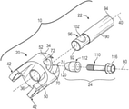
- FIG. 2 is a disassembled view of the shaft assembly
- FIGS. 3A and 3B are partial section views of the shaft assembly with a fastener assembly not installed and installed.
- FIGS. 4A and 4B are partial section views of the shaft assembly with a fastener assembly not installed and installed.
- the shaft assembly 10 may be a steering shaft assembly that may connect various components of a steering system.
- the shaft assembly 10 includes a yoke 20 , a shaft 22 , and a fastener assembly 24 .
- the yoke 20 is secured to the shaft assembly 10 by the fastener assembly 24 that provides an improved yoke 20 to shaft 22 attachment while also allowing the fastener assembly 24 to be oriented in almost any radial location of the yoke 20 .
- the yoke 20 includes a yoke body 30 having an exterior surface 32 that extends between a first end 34 and a second end 36 along a first axis 40 .
- the yoke body 30 may have a generally cylindrical shape, however other shapes or cross-sectional forms are also contemplated.
- a pair of yoke ears 42 are spaced apart from each other and extend away from the second end 36 of the yoke body 30 .
- the yoke 20 defines a first bore 50 , a second bore 52 , and a third bore 54 .
- the first bore 50 extends along the first axis 40 between the first end 34 of the yoke body 30 and the second end 36 of the yoke body 30 .
- the first bore 50 may extend completely through the yoke body 30 or may be a blind hole or blind bore.
- the second bore 52 extends at least partially across the yoke body 30 along a second axis 60 .
- the second bore 52 extends only partially across the yoke body 30 and does not extend completely across the yoke body 30 .
- the second bore 52 may extend completely across the yoke body 30 along the second axis 60 .
- the second axis 60 is disposed generally transverse to the first axis 40 .
- the second bore 52 at least partially intersects the first bore 50 , as shown in FIGS. 3A, 3B, 4A, and 4C .
- a counterbore 70 extends from the exterior surface 32 of the yoke body 30 , across the yoke body 30 , towards the second bore 52 along the second axis 60 .
- a flat 72 radially extends, relative to the second axis 60 , between the second bore 52 and the counterbore 70 .
- a notch 74 may be defined by the yoke body 30 , as shown in FIG. 2 . The notch 74 extends from the second end 36 of the yoke body 30 through the counterbore 70 towards the second end 36 of the yoke body 30 .
- the third bore 54 is disposed opposite the counterbore 70 .
- the third bore 54 extends from the exterior surface 32 of the yoke body 30 , across the yoke body 30 , towards the second bore 52 , along the second axis 60 .
- the third bore 54 defines or is provided with a plurality of threads, such that the third bore 54 is a threaded bore.
- the third bore 54 is disposed opposite the second bore 52 .
- the third bore 54 extends from the exterior surface 32 of the yoke body 30 , across the yoke body 30 , towards the second bore 52 along the second axis 60 .
- the yoke body 30 defines a stop wall 80 that defines an opening 82 .
- the stop wall 80 is disposed between the second bore 52 and the third bore 54 .
- the opening 82 of the stop wall 80 extends completely through the stop wall 80 along the second axis 60 .
- the opening 82 of the stop wall 80 may not be provided with threads.
- a flat 86 radially extends, relative to the second axis 60 , between the third bore 54 and the opening 82 of the stop wall 80 .
- the radial location of the second bore 52 and the third bore 54 along the second axis 60 may be infinitely varied or oriented in any radial location in relation to the yoke ears 42 . This enables the optimal position of the bores for installation access of the fastener assembly 24 . Furthermore, the variation of the radial location of the second bore 52 and the third bore 54 along the second axis 60 also permits the tuning of an input torque curve.
- the shaft 22 includes an outer surface 90 that extends between a first shaft end 92 and a second shaft end 94 along the first axis 40 .
- the first shaft end 92 is arranged to extend into the first bore 50 .
- An end surface of the shaft 22 that is disposed at the first shaft end 92 may be disposed parallel to the second end 36 of the yoke body 30 .
- the end surface of the shaft 22 may be disposed parallel to and/or coplanar with the second end 36 of the yoke body 30 .
- the outer surface 90 of the shaft 22 defines a notch 96 that extends from the outer surface 90 towards the first axis 40 .
- the notch 96 is disposed proximate the first shaft end 92 .
- the notch 96 may be defined by a portion of the shaft 22 having a reduced cross-sectional area as compared to the remainder of the shaft 22 .
- the reduced cross-sectional area of the shaft 22 is received within the first bore 50 .
- the notch 96 includes a surface 102 that is inclined and/or declined relative to at least one of the first axis 40 and the second axis 60 .
- the surface 102 may be a tapered surface that tapers towards the first axis 40 .
- the fastener assembly 24 extends into the second bore 52 and/or the third bore 54 along the second axis 60 .
- the fastener assembly 24 is provided with a conical wedge or tapered surface that self-aligns the fastener assembly 24 with the notch 96 of the shaft 22 to facilitate the securing of the yoke 20 to the shaft 22 .
- the conical wedge or tapered surface of the fastener assembly 24 inhibits bolt bending as compared to some current designs.
- the fastener assembly 24 includes a fastener 110 and a sleeve 112 .
- the fastener 110 may be a bolt having a fastener head 116 .
- the sleeve 112 may be provided with the fastener 110 or may be provided separately from the fastener 110 .
- the sleeve 112 is disposed about a shank of the fastener 110 and abuts the fastener head 116 .
- An outer surface of the sleeve 112 defines the conical wedge or tapered surface 120 that engages the surface 102 of the notch 96 .
- the fastener 110 having the sleeve 112 disposed about the fastener 110 , extends through the counterbore 70 , the second bore 52 , and through the opening 82 of the stop wall 80 along the second axis 60 and extends into the third bore 54 along the second axis 60 , as shown in FIGS. 3A and 3B .
- the fastener 110 engages the threads of the third bore 54 .
- the fastener head 116 is disposed on or engages the flat 72 , as shown in FIG. 3B .
- the sleeve 112 may be provided separately from the fastener 110 .
- the sleeve 112 may be inserted into the second bore 52 and held in place by a retainer 130 .
- the retainer 130 that retains the sleeve 112 extends into the second bore 52 along the second axis 60 .
- the retainer 130 holds the sleeve 112 within the second bore 52 during the assembly process.
- the fastener 110 extends through the third bore 54 , through the opening 82 of the stop wall 80 , and extends into the second bore 52 .
- the sleeve 112 is provided with or defines a plurality of inner threads. Threads of the faster 110 engage the plurality of inner threads of the sleeve 112 .
- the rotation of the fastener 110 about the second axis 60 within the sleeve 112 draws the sleeve 112 from the retainer 130 along the second axis 60 towards the stop wall 80 and/or the fastener head 116 .
- the drawing of the sleeve 112 from the retainer 130 by the rotation of the fastener 110 causes the tapered surface 120 of the sleeve 112 to engage the surface 102 of the notch 96 of the shaft 22 .
- the fastener head 116 is disposed on or engages the flat 86 , as shown in FIG. 4B .
- the retainer 130 may then be removed from the second bore 52 .
- the arrangement of the shaft assembly 10 facilitates the variation of the position of the fastener assembly 24 relative to the yoke ears 42 while simultaneously tuning the position of the shaft assembly 10 on the input torque curve.
- the arrangement of the shaft assembly 10 also inhibits or reduces the potential of the yoke ears 42 from bending or deforming while also improving the integration or assembly of the shaft assembly 10 .
Landscapes
- Engineering & Computer Science (AREA)
- General Engineering & Computer Science (AREA)
- Mechanical Engineering (AREA)
- Steering Controls (AREA)
Abstract
Description
Claims (9)
Priority Applications (1)
| Application Number | Priority Date | Filing Date | Title |
|---|---|---|---|
| US16/030,218 US11226009B2 (en) | 2018-07-09 | 2018-07-09 | Steering shaft assembly |
Applications Claiming Priority (1)
| Application Number | Priority Date | Filing Date | Title |
|---|---|---|---|
| US16/030,218 US11226009B2 (en) | 2018-07-09 | 2018-07-09 | Steering shaft assembly |
Publications (2)
| Publication Number | Publication Date |
|---|---|
| US20200011381A1 US20200011381A1 (en) | 2020-01-09 |
| US11226009B2 true US11226009B2 (en) | 2022-01-18 |
Family
ID=69101590
Family Applications (1)
| Application Number | Title | Priority Date | Filing Date |
|---|---|---|---|
| US16/030,218 Active 2040-03-28 US11226009B2 (en) | 2018-07-09 | 2018-07-09 | Steering shaft assembly |
Country Status (1)
| Country | Link |
|---|---|
| US (1) | US11226009B2 (en) |
Cited By (1)
| Publication number | Priority date | Publication date | Assignee | Title |
|---|---|---|---|---|
| US20230151846A1 (en) * | 2021-11-15 | 2023-05-18 | Sofec, Inc. | Couplers and mechanical joint assemblies including same |
Families Citing this family (3)
| Publication number | Priority date | Publication date | Assignee | Title |
|---|---|---|---|---|
| USD958747S1 (en) * | 2020-05-21 | 2022-07-26 | Shanghai Microport Medbot (Group) Co., Ltd. | Coupler |
| USD959379S1 (en) | 2020-05-21 | 2022-08-02 | Shanghai Microport Medbot (Group) Co., Ltd. | Coupler |
| USD959378S1 (en) * | 2020-05-21 | 2022-08-02 | Shanghai Microport Medbot (Group) Co., Ltd. | Coupler |
Citations (9)
| Publication number | Priority date | Publication date | Assignee | Title |
|---|---|---|---|---|
| US4576504A (en) * | 1983-05-19 | 1986-03-18 | Hartman Thomas A | Elastically conformable tapered pin-key |
| US4579477A (en) * | 1983-05-19 | 1986-04-01 | Hartman Thomas A | Pin-key assembly |
| US4862760A (en) * | 1986-08-09 | 1989-09-05 | Mazda Motor Corporation | Shift lever assembly and method of assembling |
| US5318375A (en) * | 1991-02-27 | 1994-06-07 | Jean Walterscheid Gmbh | Lock for securing a coupling sleeve |
| US5490751A (en) * | 1992-01-10 | 1996-02-13 | Nacam | Fastening device with removable axial guiding stop |
| US6443650B2 (en) | 2000-02-03 | 2002-09-03 | Nsk Ltd. | Connection structure of lateral insert type yoke and shaft |
| US7461996B2 (en) * | 2005-02-17 | 2008-12-09 | Jtekt Corporation | Erroneous assembling preventing tool for universal joint and universal joint |
| US7513709B2 (en) * | 2006-03-30 | 2009-04-07 | Jtekt Corporation | Universal joint |
| US9581205B2 (en) * | 2013-08-05 | 2017-02-28 | GM Global Technology Operations LLC | Coupling element with non-regular shaft interface |
-
2018
- 2018-07-09 US US16/030,218 patent/US11226009B2/en active Active
Patent Citations (9)
| Publication number | Priority date | Publication date | Assignee | Title |
|---|---|---|---|---|
| US4576504A (en) * | 1983-05-19 | 1986-03-18 | Hartman Thomas A | Elastically conformable tapered pin-key |
| US4579477A (en) * | 1983-05-19 | 1986-04-01 | Hartman Thomas A | Pin-key assembly |
| US4862760A (en) * | 1986-08-09 | 1989-09-05 | Mazda Motor Corporation | Shift lever assembly and method of assembling |
| US5318375A (en) * | 1991-02-27 | 1994-06-07 | Jean Walterscheid Gmbh | Lock for securing a coupling sleeve |
| US5490751A (en) * | 1992-01-10 | 1996-02-13 | Nacam | Fastening device with removable axial guiding stop |
| US6443650B2 (en) | 2000-02-03 | 2002-09-03 | Nsk Ltd. | Connection structure of lateral insert type yoke and shaft |
| US7461996B2 (en) * | 2005-02-17 | 2008-12-09 | Jtekt Corporation | Erroneous assembling preventing tool for universal joint and universal joint |
| US7513709B2 (en) * | 2006-03-30 | 2009-04-07 | Jtekt Corporation | Universal joint |
| US9581205B2 (en) * | 2013-08-05 | 2017-02-28 | GM Global Technology Operations LLC | Coupling element with non-regular shaft interface |
Cited By (1)
| Publication number | Priority date | Publication date | Assignee | Title |
|---|---|---|---|---|
| US20230151846A1 (en) * | 2021-11-15 | 2023-05-18 | Sofec, Inc. | Couplers and mechanical joint assemblies including same |
Also Published As
| Publication number | Publication date |
|---|---|
| US20200011381A1 (en) | 2020-01-09 |
Similar Documents
| Publication | Publication Date | Title |
|---|---|---|
| US11226009B2 (en) | Steering shaft assembly | |
| US8425167B2 (en) | Fastener assembly for fastening a member to workpiece | |
| US10570946B2 (en) | Blind rivet-nut and method for securing a component to a carrier | |
| US9003634B2 (en) | Blind rivet and fastening method thereof | |
| US10962040B2 (en) | Bolt arrangement, coupling arrangement and method to mount a coupling arrangement | |
| TW201420924A (en) | Shaft terminal joint and ball screw combination | |
| CN103502660A (en) | Blind rivet bolt | |
| EP2453142B1 (en) | A blind rivet and fastening method thereof | |
| US6575659B1 (en) | Conical screw connection for multi-disk shaft couplings | |
| US20180372144A1 (en) | Fastening element | |
| US20150314805A1 (en) | Coupling assembly and a method of decoupling a first member and a second member | |
| KR20070086384A (en) | Device for securing add-on and support spaced apart | |
| GB1599070A (en) | Threaded insert particularly for securing to thin sheets | |
| JP7450634B2 (en) | Bolted joint using a deformable sleeve with longitudinal grooves | |
| KR20100074051A (en) | Blind nut | |
| US10520117B2 (en) | Cooling pipe joint for motor cooling and motor cooling device provided with cooling pipe joint | |
| KR101495390B1 (en) | Structural unit | |
| US11920619B2 (en) | Expansion anchor with forwards and rearwards grooves | |
| RU2519597C2 (en) | Spherical joint pin and spherical joint | |
| EP3864306B1 (en) | Expansion anchor with bulged zone | |
| JPH11294474A (en) | Fastening method and bearing fastening method | |
| US20200147699A1 (en) | Cutter holder with reduced assembly tolerances | |
| US11940000B2 (en) | Partially-threaded projection weld nut | |
| JPH07305755A (en) | Cam follower bearing | |
| US20190107142A1 (en) | Nut |
Legal Events
| Date | Code | Title | Description |
|---|---|---|---|
| AS | Assignment |
Owner name: STEERING SOLUTIONS IP HOLDING CORPORATION, MICHIGAN Free format text: ASSIGNMENT OF ASSIGNORS INTEREST;ASSIGNORS:CYMBAL, WILLIAM D.;CASTANIER, CARL R.;PARTYKA, MIKE E.;AND OTHERS;SIGNING DATES FROM 20180705 TO 20180709;REEL/FRAME:046296/0505 Owner name: STEERING SOLUTIONS IP HOLDING CORPORATION, MICHIGA Free format text: ASSIGNMENT OF ASSIGNORS INTEREST;ASSIGNORS:CYMBAL, WILLIAM D.;CASTANIER, CARL R.;PARTYKA, MIKE E.;AND OTHERS;SIGNING DATES FROM 20180705 TO 20180709;REEL/FRAME:046296/0505 |
|
| FEPP | Fee payment procedure |
Free format text: ENTITY STATUS SET TO UNDISCOUNTED (ORIGINAL EVENT CODE: BIG.); ENTITY STATUS OF PATENT OWNER: LARGE ENTITY |
|
| STPP | Information on status: patent application and granting procedure in general |
Free format text: NON FINAL ACTION MAILED |
|
| STPP | Information on status: patent application and granting procedure in general |
Free format text: NON FINAL ACTION MAILED |
|
| STPP | Information on status: patent application and granting procedure in general |
Free format text: RESPONSE TO NON-FINAL OFFICE ACTION ENTERED AND FORWARDED TO EXAMINER |
|
| STPP | Information on status: patent application and granting procedure in general |
Free format text: FINAL REJECTION MAILED |
|
| STPP | Information on status: patent application and granting procedure in general |
Free format text: RESPONSE AFTER FINAL ACTION FORWARDED TO EXAMINER |
|
| STPP | Information on status: patent application and granting procedure in general |
Free format text: NOTICE OF ALLOWANCE MAILED -- APPLICATION RECEIVED IN OFFICE OF PUBLICATIONS |
|
| STPP | Information on status: patent application and granting procedure in general |
Free format text: PUBLICATIONS -- ISSUE FEE PAYMENT VERIFIED |
|
| STCF | Information on status: patent grant |
Free format text: PATENTED CASE |
|
| MAFP | Maintenance fee payment |
Free format text: PAYMENT OF MAINTENANCE FEE, 4TH YEAR, LARGE ENTITY (ORIGINAL EVENT CODE: M1551); ENTITY STATUS OF PATENT OWNER: LARGE ENTITY Year of fee payment: 4 |