US11225331B2 - Method and system for supplying power to an unmanned aerial vehicle - Google Patents
Method and system for supplying power to an unmanned aerial vehicle Download PDFInfo
- Publication number
- US11225331B2 US11225331B2 US16/055,770 US201816055770A US11225331B2 US 11225331 B2 US11225331 B2 US 11225331B2 US 201816055770 A US201816055770 A US 201816055770A US 11225331 B2 US11225331 B2 US 11225331B2
- Authority
- US
- United States
- Prior art keywords
- power
- uav
- battery
- supercapacitor
- heat
- Prior art date
- Legal status (The legal status is an assumption and is not a legal conclusion. Google has not performed a legal analysis and makes no representation as to the accuracy of the status listed.)
- Expired - Fee Related, expires
Links
Images


Classifications
-
- B—PERFORMING OPERATIONS; TRANSPORTING
- B64—AIRCRAFT; AVIATION; COSMONAUTICS
- B64D—EQUIPMENT FOR FITTING IN OR TO AIRCRAFT; FLIGHT SUITS; PARACHUTES; ARRANGEMENT OR MOUNTING OF POWER PLANTS OR PROPULSION TRANSMISSIONS IN AIRCRAFT
- B64D27/00—Arrangement or mounting of power plants in aircraft; Aircraft characterised by the type or position of power plants
- B64D27/02—Aircraft characterised by the type or position of power plants
- B64D27/24—Aircraft characterised by the type or position of power plants using steam or spring force
-
- H—ELECTRICITY
- H02—GENERATION; CONVERSION OR DISTRIBUTION OF ELECTRIC POWER
- H02J—ELECTRIC POWER NETWORKS; CIRCUIT ARRANGEMENTS OR SYSTEMS FOR SUPPLYING OR DISTRIBUTING ELECTRIC POWER; SYSTEMS FOR STORING ELECTRIC ENERGY
- H02J7/00—Circuit arrangements for charging or discharging batteries or for supplying loads from batteries
- H02J7/60—Circuit arrangements for charging or discharging batteries or for supplying loads from batteries including safety or protection arrangements
-
- B—PERFORMING OPERATIONS; TRANSPORTING
- B64—AIRCRAFT; AVIATION; COSMONAUTICS
- B64U—UNMANNED AERIAL VEHICLES [UAV]; EQUIPMENT THEREFOR
- B64U50/00—Propulsion; Power supply
- B64U50/30—Supply or distribution of electrical power
-
- H—ELECTRICITY
- H02—GENERATION; CONVERSION OR DISTRIBUTION OF ELECTRIC POWER
- H02J—ELECTRIC POWER NETWORKS; CIRCUIT ARRANGEMENTS OR SYSTEMS FOR SUPPLYING OR DISTRIBUTING ELECTRIC POWER; SYSTEMS FOR STORING ELECTRIC ENERGY
- H02J50/00—Circuit arrangements or systems for wireless supply or distribution of electric power
- H02J50/001—Energy harvesting or scavenging
-
- H02J7/0029—
-
- H—ELECTRICITY
- H02—GENERATION; CONVERSION OR DISTRIBUTION OF ELECTRIC POWER
- H02J—ELECTRIC POWER NETWORKS; CIRCUIT ARRANGEMENTS OR SYSTEMS FOR SUPPLYING OR DISTRIBUTING ELECTRIC POWER; SYSTEMS FOR STORING ELECTRIC ENERGY
- H02J7/00—Circuit arrangements for charging or discharging batteries or for supplying loads from batteries
- H02J7/32—Circuit arrangements for charging or discharging batteries or for supplying loads from batteries for charging batteries from a charging set comprising a non-electric prime mover rotating at constant speed
-
- H—ELECTRICITY
- H02—GENERATION; CONVERSION OR DISTRIBUTION OF ELECTRIC POWER
- H02J—ELECTRIC POWER NETWORKS; CIRCUIT ARRANGEMENTS OR SYSTEMS FOR SUPPLYING OR DISTRIBUTING ELECTRIC POWER; SYSTEMS FOR STORING ELECTRIC ENERGY
- H02J7/00—Circuit arrangements for charging or discharging batteries or for supplying loads from batteries
- H02J7/34—Parallel operation in networks using both storage and other DC sources, e.g. providing buffering
- H02J7/345—Parallel operation in networks using both storage and other DC sources, e.g. providing buffering using capacitors as storage or buffering devices
-
- B64C2201/042—
-
- B64C2201/066—
-
- B—PERFORMING OPERATIONS; TRANSPORTING
- B64—AIRCRAFT; AVIATION; COSMONAUTICS
- B64D—EQUIPMENT FOR FITTING IN OR TO AIRCRAFT; FLIGHT SUITS; PARACHUTES; ARRANGEMENT OR MOUNTING OF POWER PLANTS OR PROPULSION TRANSMISSIONS IN AIRCRAFT
- B64D31/00—Power plant control systems; Arrangement of power plant control systems in aircraft
- B64D31/02—Initiating means
- B64D31/06—Initiating means actuated automatically
-
- H—ELECTRICITY
- H02—GENERATION; CONVERSION OR DISTRIBUTION OF ELECTRIC POWER
- H02J—ELECTRIC POWER NETWORKS; CIRCUIT ARRANGEMENTS OR SYSTEMS FOR SUPPLYING OR DISTRIBUTING ELECTRIC POWER; SYSTEMS FOR STORING ELECTRIC ENERGY
- H02J2105/00—Networks for supplying or distributing electric power characterised by their spatial reach or by the load
- H02J2105/30—Networks for supplying or distributing electric power characterised by their spatial reach or by the load the load networks being external to vehicles, i.e. exchanging power with vehicles
- H02J2105/32—Networks for supplying or distributing electric power characterised by their spatial reach or by the load the load networks being external to vehicles, i.e. exchanging power with vehicles for aircrafts
-
- H—ELECTRICITY
- H02—GENERATION; CONVERSION OR DISTRIBUTION OF ELECTRIC POWER
- H02J—ELECTRIC POWER NETWORKS; CIRCUIT ARRANGEMENTS OR SYSTEMS FOR SUPPLYING OR DISTRIBUTING ELECTRIC POWER; SYSTEMS FOR STORING ELECTRIC ENERGY
- H02J7/00—Circuit arrangements for charging or discharging batteries or for supplying loads from batteries
- H02J7/60—Circuit arrangements for charging or discharging batteries or for supplying loads from batteries including safety or protection arrangements
- H02J7/65—Circuit arrangements for charging or discharging batteries or for supplying loads from batteries including safety or protection arrangements against overtemperature
-
- Y—GENERAL TAGGING OF NEW TECHNOLOGICAL DEVELOPMENTS; GENERAL TAGGING OF CROSS-SECTIONAL TECHNOLOGIES SPANNING OVER SEVERAL SECTIONS OF THE IPC; TECHNICAL SUBJECTS COVERED BY FORMER USPC CROSS-REFERENCE ART COLLECTIONS [XRACs] AND DIGESTS
- Y02—TECHNOLOGIES OR APPLICATIONS FOR MITIGATION OR ADAPTATION AGAINST CLIMATE CHANGE
- Y02T—CLIMATE CHANGE MITIGATION TECHNOLOGIES RELATED TO TRANSPORTATION
- Y02T10/00—Road transport of goods or passengers
- Y02T10/80—Technologies aiming to reduce greenhouse gasses emissions common to all road transportation technologies
- Y02T10/90—Energy harvesting concepts as power supply for auxiliaries' energy consumption, e.g. photovoltaic sun-roof
-
- Y—GENERAL TAGGING OF NEW TECHNOLOGICAL DEVELOPMENTS; GENERAL TAGGING OF CROSS-SECTIONAL TECHNOLOGIES SPANNING OVER SEVERAL SECTIONS OF THE IPC; TECHNICAL SUBJECTS COVERED BY FORMER USPC CROSS-REFERENCE ART COLLECTIONS [XRACs] AND DIGESTS
- Y02—TECHNOLOGIES OR APPLICATIONS FOR MITIGATION OR ADAPTATION AGAINST CLIMATE CHANGE
- Y02T—CLIMATE CHANGE MITIGATION TECHNOLOGIES RELATED TO TRANSPORTATION
- Y02T50/00—Aeronautics or air transport
- Y02T50/60—Efficient propulsion technologies, e.g. for aircraft
-
- Y—GENERAL TAGGING OF NEW TECHNOLOGICAL DEVELOPMENTS; GENERAL TAGGING OF CROSS-SECTIONAL TECHNOLOGIES SPANNING OVER SEVERAL SECTIONS OF THE IPC; TECHNICAL SUBJECTS COVERED BY FORMER USPC CROSS-REFERENCE ART COLLECTIONS [XRACs] AND DIGESTS
- Y02—TECHNOLOGIES OR APPLICATIONS FOR MITIGATION OR ADAPTATION AGAINST CLIMATE CHANGE
- Y02T—CLIMATE CHANGE MITIGATION TECHNOLOGIES RELATED TO TRANSPORTATION
- Y02T90/00—Enabling technologies or technologies with a potential or indirect contribution to GHG emissions mitigation
- Y02T90/40—Application of hydrogen technology to transportation, e.g. using fuel cells
Definitions
- the disclosed embodiments relate generally to mobile platforms and more particularly, but not exclusively, to methods and systems for supplying power to an unmanned aerial vehicle.
- UAVs unmanned aerial vehicles
- Heat management can be crucial to a mobile platform.
- a UAV can be electrically powered by a battery and convert electrical energy into mechanical energy.
- efficiency of such conversion can be limited, and the electrical energy can be partially converted into heat that is wasted as thermal energy.
- other various components of the UAV such as battery, camera, vision sensor, likewise can generate heat during operation. Therefore, the UAV can be severely heated. The heating can significantly impact performance and life time of electronic devices and battery on the UAV.
- a fan is installed to cool down the UAV.
- the fan can increase power consumption of the UAV.
- the fan can also generate noise and increase size of UAV.
- User experience can be affected.
- the external construction of the UAV needs to consider ventilation and selection of material. Design choice of the UAV can be significantly restricted.
- UAV unmanned aerial vehicle
- the power battery is a main power source of the UAV.
- supplying the electrical power comprises supplying supplemental power to the UAV.
- supplying the electrical power comprises determining the flying status of the UAV.
- determining the flying status of the UAV comprises ascertaining that the UAV needs enhanced power output.
- supplying the electrical power comprises supplying the electrical power to the UAV when the UAV needs enhanced power output.
- supplying the electrical power comprises determining a discharge status of the power battery of the UAV.
- determining the discharge status comprises ascertaining that the power battery is low, the power battery is disconnected and/or there is a power failure of the power battery.
- supplying the electrical power comprises supplying the electrical power to the UAV to supplement the power battery when the power battery is below a predetermined battery power threshold.
- supplying the electrical power comprises supplying the electrical power to the UAV when the power battery is disconnected.
- supplying the electrical power comprises supplying the electrical power to the UAV when the power battery is in a preselected failure mode.
- converting the heat comprises generating the electrical power via a semiconductor thermoelectric device positioned on the UAV.
- generating the electrical power comprises:
- creating the temperature difference comprises heating a first surface region of the semiconductor thermoelectric device.
- heating the first surface region comprises collecting heat produced by the power battery of the UAV.
- collecting the heat comprises collecting the heat via a heat collector.
- heating the first surface region comprises conducting the heat collected by the heat collector onto the first surface region of the semiconductor thermoelectric device.
- creating the temperature difference comprises cooling a second surface region of the semiconductor thermoelectric device.
- cooling the second surface region comprises cooling the second surface region via a heat dissipator.
- cooling the second surface region comprises absorbing heat from at least part of the second surface region via the heat dissipator.
- cooling the second surface region comprises cooling the heat dissipator with air adjacent to the UAV.
- cooling the heat dissipator comprises reducing a temperature of the air via airflow created by one or more propellers of the UAV.
- Exemplary embodiments of the disclosed methods further comprise storing the generated electrical power.
- storing the generated electrical power comprises charging a supercapacitor.
- supplying the electrical power comprises supplying stored electrical power from the supercapacitor to a propulsion unit of the UAV.
- supplying the generated electrical power comprises controlling the power supplied by the supercapacitor.
- controlling the power supply comprises controlling the charging and/or the supplying via a micro-controller unit (“MCU”).
- MCU micro-controller unit
- controlling comprises sampling a voltage and/or a current of the supercapacitor.
- controlling comprises managing the charging and/or the supplying based on the sampling.
- managing comprises activating the charging at a first time and activating the supplying at a second time that is different from the first time.
- UAV unmanned aerial vehicle
- processors individually or collectively, configured to:
- the power battery is a main power source of the UAV.
- the one or more processors are configured to supply the electrical power as a supplemental power to the UAV.
- the one or more processors are configured to determine the flying status of the UAV.
- the flying status of the UAV comprises whether the UAV needs enhanced power output.
- the one or more processors are configured to supply the electrical power to the UAV when the UAV needs enhanced power output.
- the one or more processors are configured to determine a discharge status of the power battery of the UAV.
- the discharge status comprises whether the power battery is low, the power battery is disconnected and/or there is a power failure of the power battery.
- the one or more processors are configured to supply the electrical power to the UAV to supplement the power battery when the power battery is below a predetermined battery power threshold.
- the one or more processors are configured to supply the electrical power to the UAV when the power battery is disconnected.
- the one or more processors are configured to supply the electrical power to the UAV when the power battery is in a preselected failure mode.
- Exemplary embodiments of the disclosed systems further comprise a semiconductor thermoelectric device positioned on the UAV for generating the electrical power.
- the semiconductor thermoelectric device is provided with two surface regions for capturing a temperature difference
- thermoelectric device is positioned on the UAV and configured to generate electrical power with the temperature difference.
- the temperature difference is created by heating a first surface region of the semiconductor thermoelectric device.
- the first surface region is heated by collecting heat produced by the power battery the UAV.
- Exemplary embodiments of the disclosed systems further comprise a heat collector for collecting the heat generated by the power battery.
- the heat collected is conducted onto the first surface region of the semiconductor thermoelectric device.
- the temperature difference is created by cooling a second surface region of the semiconductor thermoelectric device.
- Exemplary embodiments of the disclosed systems further comprise a heat dissipator for cooling the second surface region.
- the heat dissipator is configured to absorb heat from at least part of the second surface region.
- the heat dissipator is cooled with air adjacent to the UAV.
- Exemplary embodiments of the disclosed systems further comprise one or more propellers of the UAV for reducing a temperature of the air via airflow.
- Exemplary embodiments of the disclosed systems further comprise a supercapacitor configured to store the generated electrical power.
- the electrical power is charged into the supercapacitor.
- the supercapacitor is configured to supply the stored electrical power to a propulsion unit of the UAV.
- Exemplary embodiments of the disclosed systems further comprise a micro-controller unit (“MCU”) configured to control the power supplied by the supercapacitor.
- MCU micro-controller unit
- the MCU is configured to sample a voltage and/or a current of the supercapacitor.
- the MCU is configured to manage a charge and a supply of the supercapacitor based on the sample.
- the MCU is configured to activate the charge at a first time and the supply at a second time that is different from the first time.
- an unmanned aerial vehicle comprising:
- a propulsion unit being associated with the power supply system
- the power supply system is configured to supply power to the propulsion unit.
- managing the temperature comprises maintaining the temperature via a semiconductor thermoelectric device.
- determining the temperature comprises determining whether the temperature is less than a predetermined low temperature threshold.
- managing the temperature comprises heating the battery upon determining that the temperature is less than the predetermined low temperature threshold.
- heating the battery comprises heating the battery via the semiconductor thermoelectric device.
- heating the battery comprises conducting an electric current in a first direction to the semiconductor thermoelectric device.
- heating the battery via the semiconductor thermoelectric device comprises heating the battery via a first Peltier effect.
- heating the battery via the first Peltier effect comprises controlling the electric current to the semiconductor thermoelectric device to adjust the first Peltier effect.
- determining the temperature comprises determining whether the temperature is greater than a first predetermined high temperature threshold.
- managing the temperature comprises force cooling the battery via the semiconductor thermoelectric device upon determining that the temperature is greater than the first predetermined high temperature threshold.
- force cooling the battery comprises cooling the battery via the semiconductor thermoelectric device.
- force cooling the battery comprises conducting an electric current in a second direction to the semiconductor thermoelectric device, wherein the second direction opposites to the first direction.
- cooling the battery via the semiconductor thermoelectric device comprises cooling the battery via a second Peltier effect.
- cooling the battery comprises controlling the electric current to the semiconductor thermoelectric device to adjust the second Peltier effect.
- determining the temperature comprises determining whether the temperature is greater than a second predetermined high temperature threshold and less than the first temperature threshold.
- managing the temperature comprises cooling the battery via the semiconductor thermoelectric device upon the determining that the temperature is greater than the second predetermined high temperature threshold and less than the first temperature threshold.
- cooling the battery via the semiconductor thermoelectric device comprises forming a conductive path to the semiconductor thermoelectric device to effectuate a Seebeck effect.
- cooling the battery comprises controlling a temperature difference between a first surface region and a second surface region of the semiconductor thermoelectric device to control a force cooling effect of the semiconductor thermoelectric device.
- the second predetermined high temperature threshold is less than the first predetermined high temperature threshold.
- Exemplary embodiments of the disclosed systems further comprise generating electrical power via the temperature difference between the first surface region and the second surface region of the semiconductor thermoelectric device when the temperature is greater than the first predetermined high temperature threshold and less than the second predetermined high temperature threshold.
- generating electrical power comprises:
- conducting the heat comprises collecting the heat from the battery.
- collecting the heat comprises collecting the heat via a heat collector.
- cooling the second surface region of the semiconductor thermoelectric device comprises conducting the heat to a heat dissipator.
- cooling the second surface region comprises exposing at least a portion of the heat dissipator to air adjacent to the semiconductor thermoelectric device.
- exposing the dissipator comprises cooling the air adjacent of the semiconductor thermoelectric device with an airflow being created by an unmanned aerial vehicle (“UAV”) accommodating the semiconductor thermoelectric device.
- UAV unmanned aerial vehicle
- Exemplary embodiments of the disclosed systems further comprise storing the generated electrical power.
- storing the generated electrical power comprises charging the electrical power into a supercapacitor.
- Exemplary embodiments of the disclosed systems further comprise supplying the generated electrical power from the supercapacitor to one or more power-consuming components of the UAV.
- supplying the generated electrical power comprises controlling the power supply from the supercapacitor.
- the battery is within an intelligent battery module.
- the battery is a power battery of an unmanned aerial vehicle.
- a system for protecting a battery comprising:
- processors individually or collectively, operate to:
- Exemplary embodiments of the disclosed systems further comprise a semiconductor thermoelectric device configured to maintain the temperature of the battery.
- the one or more processors are configured to determine whether that the temperature is less than a predetermined low temperature threshold.
- the semiconductor thermoelectric device is configured to heat the battery based upon determining that the temperature is less than the predetermined low temperature threshold.
- the one or more processors are configured to conduct an electric current in a first direction to the semiconductor thermoelectric device.
- the semiconductor thermoelectric device is configured to heat the battery via a first Peltier effect.
- the one or more processors are configured to control the electric current to the semiconductor thermoelectric device to adjust the first Peltier effect.
- the one or more processors are configured to determine whether the temperature is greater than a first predetermined high temperature threshold.
- the semiconductor thermoelectric device is configured to forcedly cool the battery upon the temperature is determined greater than a first predetermined high temperature threshold.
- the one or more processors are configured to conduct an electric current in a second direction to the semiconductor thermoelectric device, wherein the second direction opposites to the first direction.
- the semiconductor thermoelectric device is configured to forcedly cool the battery by the electric current via a second Peltier effect.
- the one or more processors are configured to control the electric current to the semiconductor thermoelectric device to adjust the second Peltier effect.
- the one or more processors are configured to determine whether the temperature is greater than a second predetermined high temperature threshold and less than the first temperature threshold.
- the semiconductor thermoelectric device is configured to cool the battery upon the determined temperature when the temperature is greater than the second predetermined high temperature threshold and less than the first temperature threshold.
- the semiconductor thermoelectric device is configured to cool the battery by forming a conductive path to effectuate a Seebeck effect.
- the one or more processors are configured to control a temperature difference between a first surface region and a second surface region of the semiconductor thermoelectric device to control the Seebeck effect.
- the second predetermined high temperature threshold is less than the first predetermined high temperature threshold.
- the semiconductor thermoelectric device is configured to generate electrical power via the temperature difference between the first surface region and the second surface region of the semiconductor thermoelectric device when the temperature is greater than the first predetermined high temperature threshold and less than the second predetermined high temperature threshold.
- the semiconductor thermoelectric device is arranged for conducting the heat generated by the battery to the first surface region of the semiconductor thermoelectric device and for cooling the second surface region of the semiconductor thermoelectric device.
- Exemplary embodiments of the disclosed systems further comprise a heat collector for collecting the heat generate by the battery.
- Exemplary embodiments of the disclosed systems further comprise a heat dissipator for cooling the second surface region the semiconductor thermoelectric device.
- At least a portion of the heat dissipator is exposed to air adjacent to the semiconductor thermoelectric device.
- the air adjacent of the semiconductor thermoelectric device is cooled with an airflow being created by an unmanned aerial vehicle (“UAV”) accommodating the semiconductor thermoelectric device.
- UAV unmanned aerial vehicle
- Exemplary embodiments of the disclosed systems further comprise a supercapacitor for storing the generated electrical power.
- the supercapacitor supplies the stored electrical power to one or more power-consuming components of the UAV.
- the one or more processors are configured to control the power supply from the supercapacitor.
- the battery is within an intelligent battery module.
- the battery is a power battery of an unmanned aerial vehicle.
- An intelligent battery module comprising:
- system is configured to control a temperature inside the housing in order to meet temperature requirements of the energy storage components.
- An unmanned aerial vehicle comprising:
- system is configured to control a temperature inside the fuselage in order to meet temperature requirements of the battery.
- FIG. 1 is an exemplary diagram illustrating an embodiment of an unmanned aerial vehicle (UAV) comprising a power supply system.
- UAV unmanned aerial vehicle
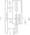
- FIG. 2 is an exemplary diagram illustrating an alternative embodiment of the UAV of FIG. 1 , wherein the UAV includes a power battery.
- FIG. 3 is an exemplary diagram illustrating an alternative embodiment of the power supply system of FIG. 1 , wherein the power supply system includes a thermoelectric device.
- FIG. 4 is an exemplary top-level flow chart illustrating an embodiment of a method for supplying power to the UAV of FIG. 1 .
- FIG. 5 is an exemplary diagram illustrating an alternative embodiment of the thermoelectric device of FIG. 3 , wherein the thermoelectric device includes a semiconductor thermoelectric device.
- FIG. 6 is an exemplary diagram illustrating another alternative embodiment of the thermoelectric device of FIG. 3 , wherein the thermoelectric device comprises a plurality of thermocouples.
- FIG. 7 is an exemplary flow chart illustrating an alternative embodiment of the method of FIG. 1 , wherein the method includes creating a temperature difference using the power supply system.
- FIG. 8 is an exemplary diagram illustrating another alternative embodiment of the thermoelectric device of FIG. 3 , wherein the thermoelectric device includes a heat collector.
- FIG. 9 is an exemplary diagram illustrating another alternative embodiment of the thermoelectric device of FIG. 3 , wherein the thermoelectric device includes a heat dissipator.
- FIG. 10 is an exemplary diagram illustrating an alternative embodiment of the thermoelectric device of FIG. 9 , wherein the heat dissipator is at least partially exposed to air outside the UAV that accommodates the thermoelectric device.
- FIG. 11 is an exemplary diagram illustrating another alternative embodiment of the thermoelectric device of FIG. 9 , wherein the heat dissipator is at least partially exposed to air flow generated by a UAV that accommodates the thermoelectric device.
- FIG. 12 is an exemplary diagram illustrating another alternative embodiment of the power supply system of FIG. 1 , wherein the power supply system includes a supercapacitor.
- FIG. 13 is an exemplary diagram illustrating an alternative embodiment of the power supply system of FIG. 12 , wherein the power supply system includes a micro-controller unit (MCU) for controlling the supercapacitor.
- MCU micro-controller unit
- FIG. 14 is an exemplary diagram illustrating an embodiment of a battery protection system for protecting a battery.
- FIG. 15 is an exemplary top-level flow chart illustrating an embodiment of a method for protecting a battery using the battery protection system of FIG. 14 .
- FIG. 16 is an exemplary diagram illustrating an alternative embodiment of the battery protection system of FIG. 14 , wherein the battery protection system is configured to heat the battery via a first Peltier effect.
- FIG. 17 is an exemplary diagram illustrating another alternative embodiment of the battery protection system of FIG. 14 , wherein the system is configured to cool the battery via a second Peltier effect.
- FIG. 18 is an exemplary diagram illustrating another alternative embodiment of the system of FIG. 14 , wherein the system is configured to cool the battery via a Seebeck effect.
- FIG. 19 is an exemplary diagram illustrating another alternative embodiment of the system of FIG. 14 , wherein the system includes a supercapacitor.
- FIG. 20 is an exemplary diagram illustrating an embodiment of an intelligent battery module that includes the system of FIG. 14 .
- FIG. 21 is an exemplary diagram illustrating an embodiment of an UAV that includes the system of FIG. 14 .
- the UAV 100 is an aircraft without a human pilot (or operator) onboard the vehicle whose flight is controlled autonomously or by a remote pilot (or sometimes both).
- the UAV 100 is finding increased usage in various applications involving various aerial operations, such as data-gathering or delivery.
- the present systems and methods are suitable for many types of UAVs 100 including, without limitation, quadcopters (also referred to a quadrotor helicopters or quad rotors), single rotor, dual rotor, trirotor, hexarotor, and octorotor rotorcraft UAVs 100 , fixed wing UAVs 100 , and hybrid rotorcraft-fixed wing UAVs 100 .
- FIG. 1 shows the UAV 100 as including a power supply system 200 coupled to an energy component 300 .
- the energy component 300 can include any component onboard the UAV 100 that can generate heat 201 as a byproduct of the energy component 300 .
- the heat 201 can be provided to the power supply system 200 .
- the power supply system 200 can convert the heat 201 into electrical power 202 .
- the power supply system 200 can supply the electrical power 202 to the UAV 100 .
- the power supply system 200 of the UAV 100 is associated with a power battery 310 .
- the power battery 310 can be an energy component 300 and can include any device that can be a main power source for powering the UAV 100 . Stated somewhat differently, the UAV 100 can obtain power from the power battery 310 in any circumstances unless the power battery 310 is not available.
- An exemplary power battery 310 can include any conventional type of battery including, but not limited to, lead-acid battery, lithium air battery, lithium-ion battery, nickel-cadmium battery, nickel-metal hydrogen battery, or a combination thereof.
- the power battery can be rechargeable.
- FIG. 2 shows the energy component 300 as including one or more power-consuming components 320 .
- Each of the power-consuming components 320 can include a component aboard the UAV 100 that consumes power.
- the power-consuming components 320 can include a flight controller 330 for directing some or all operations of the UAV 100 .
- the power-consuming components 320 can include a propulsion unit 340 for providing a force to propel the UAV 100 .
- the propulsion unit 340 can include one or more propellers 342 (shown in FIG. 11 ) each being coupled to an actuation mechanism 341 (shown in FIG. 11 ).
- An exemplary actuation mechanism can include a motor.
- the propulsion unit 340 can be in communication with the flight controller 330 .
- the flight controller 330 can send a motor control signal to the actuation mechanism 341 .
- the motor control signal can control operation of the motor.
- the propulsion unit 340 can include a motor controller in communication with the flight controller 330 . Based on instruction from the flight controller 330 , the propulsion unit 340 can send the motor control signal to the motor for operating the motor.
- the power-consuming components 320 can include at least one application unit 350 .
- the application unit 350 can include any component aboard the UAV 100 that implements computation function that compliments and/or assists function of the flight controller 330 .
- the application unit 350 can include an imaging device such as a camera, a sensor such as vision sensor, and/or a communication module for data transmission such as image transmission.
- Each of the energy components 300 can generate the heat 201 during operation.
- the power supply system 200 can convert the heat 201 into the electrical power 202 .
- the power supply system 200 can be electrically connected with a selected power-consuming component 320 to supply the electrical power 202 to the selected power-consuming component 320 .
- the flight controller 330 can send a flying status 332 of the UAV 100 to the power supply system 200 .
- the flying status 332 can include any information related to operations of the UAV 100 .
- Exemplary flying status 332 can include parameters of power supplied from the power battery 310 and/or power requirement of a current operation of the UAV 100 .
- the flying status 332 can indicate whether the power supplied from the power battery 310 is sufficient for the current operation of the UAV 100 .
- the power battery 310 can send a main power status 312 to the power supply system 200 .
- the main power status 312 can include any information related to status of the power battery 310 .
- Exemplary main power status 312 can include a discharge status of the main power source 310 .
- the discharge status can include parameters of power supplied from the power battery 310 , such as an output current and/or an output voltage of the power battery 310 .
- FIG. 2 shows the power supply system 200 as receiving the main power status 312 from the power battery 310 for illustrated purposes only
- the power supply system 200 can receive the main power status 312 from another component of the UAV 100 .
- the power battery 310 can be in communication with the flight controller 330 .
- the flight controller 330 can obtain and/or ascertain the main power status 312 and send the same to the power supply system 200 .
- FIG. 3 shows an exemplary power supply system 200 .
- the power supply system 200 is shown as including a processor 210 .
- the processor 210 can include one or more general-purpose microprocessors (for example, single or multi-core processors), application-specific integrated circuits, application-specific instruction-set processors, graphics processing units, physics processing units, digital signal processing units, coprocessors, network processing units, encryption processing units, and the like. Although one processor 210 is shown in FIG. 3 for illustrated purposes only, the processor 210 can include any number of uniform and/or different processors 210 .
- the power supply system 200 can include one or more additional hardware components and/or software components for performing the power supply functions and operations described herein.
- Exemplary additional hardware components include, but are not limited to, a memory 220 , alternatively referred to herein as a non-transitory computer-readable storage medium.
- the memory 220 can include any computer-readable storage medium for storing machine-executable code.
- Exemplary memory 220 can include a random access memory (RAM), static RAM, dynamic RAM, read-only memory (ROM), programmable ROM, erasable programmable ROM, electrically erasable programmable ROM, flash memory, secure digital (SD) card, magnetic disk, optical disk, etc.
- Instructions for execution by the processor 210 can be stored on the memory 220 as a computer program product.
- the processor 210 and the memory 220 can be provided in an integrated and/or discrete manner. Although one memory 220 is shown in FIG. 3 for illustrated purposes only, the power supply system 200 can include any number of uniform and/or different
- the power supply system 200 can include at least one input/output interface 230 .
- Exemplary input/output interface 230 can include, but are not limited to, universal serial bus (USB), digital visual interface (DVI), display port, serial ATA (SATA), IEEE 1394 interface (also known as FireWire), serial, video graphics array (VGA), super video graphics array (SVGA), small computer system interface (SCSI), high-definition multimedia interface (HDMI), audio ports, and/or proprietary input/output interfaces.
- USB universal serial bus
- DVI digital visual interface
- SATA serial ATA
- IEEE 1394 interface also known as FireWire
- serial video graphics array
- SVGA super video graphics array
- SCSI small computer system interface
- HDMI high-definition multimedia interface
- audio ports and/or proprietary input/output interfaces.
- the power supply system 200 can communicate with the flight controller 330 and/or the power battery 310 (shown in FIG. 2 ) via the input/output interface 230 .
- the power supply system 200 can include at least one thermoelectric device 240 electrically coupled to the processor 210 .
- the thermoelectric device 240 can include any type of device that can achieve conversion between the heat 201 (shown in FIG. 2 ) and the electrical energy 202 (shown in FIG. 2 ) based on a thermoelectric effect. Stated somewhat differently, the thermoelectric device 240 can realize conversion between a temperature difference and an electric voltage and/or an electric current.
- the thermoelectric device 240 can be made of a thermoelectric material. Based on the type of thermoelectric material, the thermoelectric device 240 can include, for example, a metallic thermoelectric device, a semiconductor thermoelectric device, an inorganic thermoelectric device, an organic thermoelectric device, or a combination thereof.
- the thermoelectric device 240 can include a semiconductor thermoelectric device that is made of one or more semiconductor thermoelectric materials, including, but not limited to, doped lead telluride alloy (PbTe), inorganic clathrates of group III and/or IV atoms, magnesium group IV compounds, silicides, organic semiconductors, silicon-germanium, PbTe/PbSeTe quantum dot superlattice, nanocrystalline transition metal silicides, graphene, and/or tin selenide.
- semiconductor thermoelectric device that is made of one or more semiconductor thermoelectric materials, including, but not limited to, doped lead telluride alloy (PbTe), inorganic clathrates of group III and/or IV atoms, magnesium group IV compounds, silicides, organic semiconductors, silicon-germanium, PbTe/PbSeTe quantum dot superlattice, nanocrystalline transition metal silicides, graphene, and/or tin selenide.
- PbTe doped
- the processor 210 , the memory 220 and/or the input/output interface 240 can be configured to communicate, for example, using hardware connectors and buses and/or in a wireless manner.
- the power supply system 200 can be at least partially integrated with the power battery 310 (shown in FIG. 2 ) and/or the flight controller 330 (shown in FIG. 2 ).
- the processor 210 and/or the memory 220 can be at least partially integrated with the power battery 310 and/or the flight controller 330 .
- FIG. 4 an exemplary method 400 for supplying power to the UAV 100 is shown.
- the method 400 can be implemented on the power supply system 200 set forth above with reference to FIG. 1 .
- the heat 201 produced by at least one energy component 300 of the UAV 100 can be converted, at 410 , into the electrical power 202 .
- the electrical power 202 can be supplied to the UAV 100 , at 420 , based on the flying status 332 of the UAV 100 and/or the discharge status 312 of the power battery of the UAV 100 .
- the power battery 310 can be the main power source of the UAV 100 .
- the power supply system 200 can determine the flying status 332 and/or the discharge status 312 . Based on the flying status 332 and/or the discharge status 312 , the power supply system 200 can ascertain whether the UAV 100 needs a supplemental power. Upon ascertaining that the UAV 100 needs the supplemental power, the power supply system 200 can supply the electrical power 202 as the supplemental power to the UAV 100 .
- the UAV 100 may need the supplemental power in a situation that the UAV 100 needs enhanced power output, the power battery 310 is low, the power battery 310 is disconnected, and/or there is a power failure of the power battery 310 .
- the power battery 310 can be low when a power level of the power battery 310 is below a predetermined threshold value.
- the UAV 100 may need enhanced power output.
- the flying status 332 can indicate that the UAV 100 is accelerating, ascending, and/or moving against a head wind; so, more propulsion is needed.
- power output from the power battery needs to be enhanced within a short time.
- the power supply system 200 can supply the electrical power 202 to supplement the power output from the power battery.
- the power supply system 200 can help to ensure that the UAV 100 is sufficiently powered.
- the power battery 310 can avoid outputting power at or beyond highest capacity; so, safety of the power battery 310 can be ensured.
- the power battery 310 can be low, e.g., below a predetermined battery power threshold. Stated somewhat differently, the power battery 310 can be defective or operate in adverse condition such as low temperature; so, power output from the power battery 310 can be less than requirement of the UAV 100 .
- the discharge status 312 can indicate output voltage and/or current of the power battery 310 being less than a requirement indicated in the flying status 332 .
- the power supply system 200 can supply the electrical power 202 to supplement the power output from the power battery. Thus, the power supply system 200 can advantageously ensure that the UAV 100 is sufficiently powered for safe operation.
- the power battery 310 can become disconnected from other components of the UAV 100 .
- the power battery 310 can be disconnected for replacement.
- the power battery 310 can be disconnected due to a failure of electrical connection between the power battery 310 and another component of the UAV 100 .
- the flying status 332 can indicate a failure of power output and/or communication failure with the power battery 310 , e.g., the power battery is in a preselected failure mode.
- the power supply system 200 can thus supply the electrical power 202 to the UAV 100 for uninterrupted power supply.
- the power supply system 200 can supply the electrical power 202 to the flight controller 330 and/or the propulsion unit 340 (shown in FIG. 2 ).
- the flight controller 330 can optionally instruct the propulsion unit 340 for executing an emergency landing.
- the power supply system 200 can advantageously ensure that the UAV 100 is powered for safe operation.
- the power battery 310 can have a power failure. Stated somewhat differently, the power battery 310 can be defective or damaged during operation. For example, the flying status 332 can indicate a failure of power output.
- the power supply system 200 can thus supply the electrical power 202 to the UAV 100 for uninterrupted power supply.
- the flight controller 330 can switch from the power battery to the power supply system 200 for power supply.
- the power supply system 200 can advantageously ensure that the UAV 100 is continuously powered for safe operation.
- the method 400 can advantageously implement heat management for the UAV 100 without a need for installing a fan.
- the thermoelectric device 240 can have a volume that is smaller than volume of the fan. The thermoelectric device 240 does not generate significant noise. User experience can thus be improved. Structure of the UAV 100 does not need to consider ventilation required by the fan. Construction of the UAV 100 can have less restriction and more flexibility.
- the heat 201 can be used for generating the electrical power 202 to power components of the UAV 100 and/or extend operation duration of the UAV 100 . Performance and life time of electronic devices and battery on the UAV 100 can be improved and the UAV 100 can be more energy efficient.
- thermoelectric device 240 can include at least one thermocouple 246 sandwiched between a first surface region 241 and a second surface region 242 .
- the surface regions 241 , 242 can each include a thermally conductive substrate.
- the first surface region 241 can be heated by the heat 201 .
- the first surface region 241 can have a first temperature T 1 .
- Heat 201 A also referred to as dissipated heat 201 A, can escape from the thermoelectric device 240 via the second surface region 242 .
- the second surface region 242 can be cooled and thus have a second temperature T 2 , where T 2 is less than T 1 .
- the thermocouple 246 can include two different thermoelectric materials that can include, as illustratively shown in FIG. 5 , an n-type semiconductor 243 and a p-type semiconductor 244 .
- a first end region E 1 of each of the semiconductors 243 , 244 can be electrically connected to a first conductor 245 A.
- the first conductor 245 A can allow thermal conduction between the first end region E 1 and the first surface region 241 .
- Second end regions E 2 of the semiconductors 243 , 244 can be connected to respective ends of a load 247 via a second conductor 245 B to form a circuit 248 .
- the second conductor 245 B can allow thermal conduction between each of the second end regions E 2 and the second surface region 242 .
- the load 247 can include one or more power-consuming components 320 as set forth above with reference to FIG. 2 .
- a temperature difference T 1 ⁇ T 2 between the first temperature T 1 and the second temperature T 2 can result in a shift of electron energy levels in the semiconductors 243 , 244 . Accordingly, electrons 243 C in the n-type semiconductor 243 and holes 244 C in the p-type semiconductor 244 can diffuse and/or drift toward the second conductor 245 B.
- a current 203 can thus be generated via a Seebeck effect. In certain embodiments, the current 203 can increase monotonically with an increase of the temperature difference T 1 ⁇ T 2 . For example, the current 203 can have a proportional relationship with the temperature difference T 1 ⁇ T 2 .
- One or more switch devices can be located along the circuit 248 .
- the switch devices can be turned on and/or off controllably, for example, via control by the processor 210 shown in FIG. 3 .
- the processor 210 can thus control generation of the current 203 by the thermoelectric device 240 and/or power supply to the load 247 .
- thermoelectric device 240 can include two adjacent thermocouples 246 each arranged between the surface regions 241 , 242 . As shown in FIG. 6 , the two adjacent thermocouples 246 A, 246 B can be electrically connected in series. The n-type semiconductor 243 of the thermocouple 246 A can be electrically connected with the p-type semiconductor 244 of the thermocouple 246 B via the second conductor 245 B. Compared with the thermoelectric device 240 shown in FIG. 5 , two thermocouples 246 can advantageously increase voltage capability of the thermoelectric device 240 .
- thermoelectric device 240 can include any number of thermocouples 246 interconnected between the surface regions 241 , 242 , without limitation.
- FIG. 6 shows the thermocouples 246 as being connected in series for illustrated purposes only, the thermocouples 246 can be connected in series, in parallel, or a combination thereof.
- FIG. 7 an alternative embodiment of the method 400 is shown. Exemplary details for converting the heat 201 into the electrical power 202 , at 410 , are shown in FIG. 7 .
- the temperature difference T 1 ⁇ T 2 can be created, at 411 , between the two surface regions 241 , 242 of the thermoelectric device 240 positioned on the UAV 100 .
- the first surface region 241 can be in contact with and/or in proximity with an energy component 300 as set forth above with reference to FIG. 1 , to be heated by the energy component 300 .
- the second surface region 242 can be positioned distally from the energy component 300 , and thus have the temperature T 2 less than T 1 .
- the temperature difference T 1 ⁇ T 2 can thus be created.
- the electrical power 202 can be generated, at 412 , with the temperature difference T 1 ⁇ T 2 .
- the temperature difference T 1 ⁇ T 2 can create a voltage difference between the two conductors 245 A, 245 B shown in FIG. 5 .
- the power supply system 200 is shown as including a heat collector 250 coupled to the thermoelectric device 240 .
- the heat collector 250 can be coupled to the thermoelectric device 240 in any manner. As shown in FIG. 8 , for example, the heat collector 250 and the thermoelectric device 240 can be in direct contact with the first surface region 241 to allow thermal conduction therebetween.
- the heat collector 250 can collect the heat 201 to transfer and/or conduct the heat 201 to the first surface region 241 .
- the heat collector 250 can have high thermal conductivity.
- An exemplary heat collector 250 can be made of thermally conductive materials including, but not limited to, copper, aluminum, silver, graphite and/or the like. Additionally and/or alternatively, the heat collector 250 can have a large surface area for enhanced heat absorption.
- a structure of an exemplary heat collector 250 can have a shape of heat pipe, fin, sheet, and/or belt. Additionally and/or alternatively, in areas where surface contact forms between the heat collector 250 and the first surface region 241 , thermally conductive filler such as thermal silica gel can be applied to enhance the surface contact.
- the heat collector 250 can collect the heat 201 in a manner that can be more effective than the thermoelectric device 240 .
- the temperature difference T 1 ⁇ T 2 can be increased to result in increased power generation.
- the power supply system 200 is shown as including a heat dissipator 260 coupled to the thermoelectric device 240 .
- the heat collector 250 can be coupled to the thermoelectric device 240 in any manner. As shown in FIG. 8 , for example, the heat collector 250 and the thermoelectric device 240 can be in direct contact with the second surface region 242 to allow thermal conduction therebetween.
- the heat dissipator 260 can absorb heat from at least part of the second surface region 242 for dissipation as the dissipated heat 201 A. Thus, the heat dissipator 260 can cool the second surface region 242 of the thermoelectric device 240 .
- the heat dissipator 260 can have high thermal conductivity.
- An exemplary heat dissipator 260 can be made of thermally conductive materials including, but not limited to, copper, aluminum, silver, graphite and/or the like. Additionally and/or alternatively, the heat dissipator 260 can have a large surface area for enhanced heat absorption.
- a structure of an exemplary heat dissipator 260 can have a shape of heat pipe, fin, sheet, and/or belt. Additionally and/or alternatively, in areas where surface contact forms between the heat dissipator 260 and the second surface region 242 , thermally conductive filler such as thermal silica gel can be applied to enhance the surface contact.
- the power supply system 200 is shown as including a supercapacitor 270 electrically connected to the thermoelectric device 240 .
- the thermoelectric device 240 can charge the electrical power 202 into the supercapacitor 270 .
- the supercapacitor 270 can store the electrical power 202 .
- the power supply system 200 can supply the electrical power 202 from the supercapacitor 270 to one or more of the power-consuming components 320 of the UAV 100 .
- the power supply system 200 can supply the electrical power 202 from the supercapacitor 270 to the propulsion unit 340 as set forth above with reference to FIG. 1 .
- FIG. 12 shows the power supply system 200 as including the supercapacitor 270 for illustrated purposes only, the power supply system 200 can include any other energy storage devices for storing the electrical power 202 .
- exemplary energy storage devices can include, but are not limited to, tantalum capacitors, electrolytic capacitors, electrochemical capacitors, ultracapacitors, and/or rechargeable batteries.
- the MCU 280 can include one or more sensors for measuring electrical parameters of the supercapacitor 270 .
- Exemplary electrical parameters can include a voltage and/or a current of the supercapacitor 270 . Based on the electrical parameters, the MCU 280 can manage charging the supercapacitor 270 and/or supplying the electrical power 202 .
- the MCU 280 can turn on the charge switch 282 .
- the MCU 280 can optionally turn off the supplying switch 284 so the supercapacitor 270 is not able to supply the electrical power 202 to the power-consuming components 320 .
- the MCU 280 can collect the voltage and/or the current of the supercapacitor 270 in real time. When the voltage and/or the current of the supercapacitor 270 meets power supply requirement of the power-consuming component 320 , the MCU 280 can turn on the supplying switch 284 so the supercapacitor 270 can supply the electrical power 202 to the power-consuming components 320 .
- FIG. 13 shows the MCU 280 as controlling the charge switch 282 and/or the supply switch 284 for illustrated purposes only, the charge switch 282 and/or the supply switch 284 can be at least partially controlled by the processor 210 as set forth above with reference to FIG. 3 . In certain embodiments, the MCU 280 can be at least partially integrated with the processor 210 .
- a temperature sensor 740 can be positioned at least partially in proximity to, and/or in contact with, the energy storage component 720 .
- the temperature sensor 740 can sense a surface temperature of the energy storage component 720 .
- the temperature sensor 740 can be in communication with the processor 610 via the input/output interface 630 , for example, for the processor 610 to obtain a temperature status of the energy storage component 720 .
- the battery protection system 600 can maintain the temperature of the battery 700 within a predetermined range of operation temperature. Thus, overheating and/or overcooling of the battery 700 can be prevented. Performance and/or life time of the battery 700 can be improved.
- the electric current 692 can flow in the first direction by flowing from the p-type semiconductor 644 to the n-type semiconductor 643 . Stated somewhat differently, the electric current 692 flowing in the first direction shown in FIG. 16 can reach the p-type semiconductor 644 prior to reaching the n-type semiconductor 643 .
- the first surface region 641 and the second surface region 642 can respectively become a hot region and a cold region. That is, the temperature T 1 of the first surface region 641 can be greater than the temperature T 2 of the second surface region 642 .
- the first surface region 641 can transfer heat 604 A to the battery 700 to heat the battery 700 .
- the electric current 692 can generate the heat 604 A via a first Peltier effect.
- the battery protection system 600 can heat the battery 700 upon determining whether the temperature of the battery 700 is less than a predetermined low temperature threshold TL.
- overcooling of the battery 700 can be prevented.
- FIG. 16 shows the battery 700 as being positioned from the first surface region 641 for illustrated purposes only, the battery 700 can be at least partially in contact with the first surface region 641 to advantageously improve thermal conduction therebetween.
- the power source 690 is shown as provided the electric current 692 flowing in a second direction. That is, electrons 643 C in the n-type semiconductor 643 and holes 644 C in the p-type semiconductor 644 can diffuse and/or drift toward the second conductor 645 B from the first conductor 645 A, resulting in heat being carried by the electrons 643 C and/or holes 644 C toward the second conductor 645 B. As shown in FIG. 16 , the electric current 692 can flow in the second direction by flowing from the n-type semiconductor 643 to the p-type semiconductor 644 . Stated somewhat differently, the electric current 692 flowing in the second direction can reach the n-type semiconductor 643 prior to reaching the p-type semiconductor 644 .
- the first surface region 641 and the second surface region 642 can respectively become a cold region and a hot region. That is, the temperature T 1 of the first surface region 641 can be less than the temperature T 2 of the second surface region 642 .
- the first surface region 641 can draw heat 604 B from the battery 700 to cool, and/or force cool, the battery 700 .
- the electric current 692 can draw the heat 604 B via a second Peltier effect.
- the battery protection system 600 can force cool the battery 700 upon determining whether the temperature of the battery 700 is greater than a first predetermined high temperature threshold T H1 .
- overheating of the battery 700 can be prevented.
- the processor 610 can control magnitude of the electric current 692 via the power source 690 to adjust the second Peltier effect. Stated somewhat differently, the processor 610 can control the magnitude of the electric current 692 to adjust temperature difference across the thermoelectric device 640 and/or to adjust the amount of the heat 604 B for force cooling the battery 700 . For example, the magnitude of the electric current 692 can be at least partially based on a temperature difference between the battery 700 and first predetermined high temperature threshold T H1 . For example, the processor 610 can control the magnitude of the electric current 692 to be greater when the temperature difference is greater.
- thermoelectric device 640 is shown as being electrically connected to the load 647 to form the circuit 648 in a similar manner as set forth above with reference to FIG. 5 .
- the circuit 648 can be a conductive path for effectuating the Seebeck effect via the thermoelectric device 640 .
- the heat 601 produced by the battery 700 can be conducted to the first surface region 641 of the thermoelectric device 640 .
- the dissipated heat 601 A can escape form the thermoelectric device 640 via the second surface region 642 .
- the second surface region 642 of the thermoelectric device 640 can be cooled.
- the temperature difference T 1 ⁇ T 2 between the first surface region 641 and the second surface region 642 can generate the electrical power 602 (shown in FIG. 19 ).
- the temperature difference T 1 ⁇ T 2 can generate an electric potential difference between the first surface region 641 and the second surface region 642 and accordingly generate the current 603 for flowing through the load 647 .
- the battery protection system 600 can control the temperature difference T 1 ⁇ T 2 between the first surface region 641 and the second surface region 642 of the thermoelectric device 640 to control the Seebeck effect of the thermoelectric device 640 .
- the processor 610 can control switch devices (not shown) for connecting one or more selected power-consuming components 720 (shown in FIG. 19 ) as the load 647 to form the circuit 648 . Stated somewhat differently, the processor 610 can select the power-consuming components 720 to be connected as the load 647 . Based on power consumption of the connected power-consuming components 720 , the load 647 can have different total power consumption. Magnitude of the current 603 can thus be adjusted based on selection of the power-consuming components 720 .
- efficiency of cooling the battery 700 can be adjusted by adjusting distance between the battery 700 and the first surface region 641 .
- the temperature difference T 1 ⁇ T 2 can be increased.
- the electric potential difference generated across the thermoelectric device 640 can be increased, and the current 603 can be increased even if the load 647 remains constant. Efficiency of cooling the battery 700 can be increased.
- FIG. 18 shows the battery 700 as being positioned from the first surface region 641 for illustrated purposes only, the battery 700 can be at least partially in contact with the first surface region 641 to advantageously improve thermal conduction therebetween and/or increase efficiency to cool the battery 700 .
- the battery protection system 600 can force cool the battery 700 using the Seebeck effect upon determining whether the temperature of the battery 700 is greater than the first predetermined high temperature threshold T H1 .
- overheating of the battery 700 can be prevented.
- the battery protection system 600 can force cool the battery 700 using the Seebeck effect upon determining whether the temperature of the battery 700 is greater than a second predetermined high temperature threshold T H2 and lower than the first high temperature threshold T H1 .
- the second high temperature threshold T H2 can be lower than the first high temperature threshold T H1 .
- the battery protection system 600 can force cool the battery 700 using the second Peltier effect. Because the second Peltier effect can have a higher cooling efficiency than the Seebeck effect, the battery 700 can advantageously be cooled at a higher efficiency when cooling is of greater urgency.
- the battery protection system 600 can include the heat collector 250 (shown in FIG. 8 ) coupled to the thermoelectric device 640 for collecting the heat 601 from the battery 700 . Additionally and/or alternatively, the battery protection system 600 is shown as including the heat dissipator 260 (shown in FIG. 9 ) coupled to the thermoelectric device 640 for cooling the second surface region 642 .
- the battery 700 can be the power battery 310 (shown in FIG. 1 ) used for powering the UAV 100 shown in FIG. 1 .
- the heat dissipator 260 can be at least partially exposed to air adjacent to the thermoelectric device 640 in a similar manner as set forth above with reference to FIG. 10 .
- the heat dissipator 260 and/or the air can be cooled by the air flow 120 creased in a similar manner as set forth above with reference to FIG. 11 .
- the battery protection system 600 is shown as including the supercapacitor 670 electrically connected to the thermoelectric device 640 .
- the supercapacitor 670 can be used for storing the electrical power 602 generated by the thermoelectric device 640 .
- the supercapacitor 670 can supply the electrical power 602 to any suitable load (not shown).
- the load can include any power-consuming device and/or, as shown in FIG. 19 , can include the power-consuming component 720 .
- the battery protection system 600 can control the supplying of the electrical power 602 in a manner as set forth above with reference to FIG. 13 .
- the intelligent battery module 900 can include a housing 910 for accommodating the battery 700 .
- the battery 700 can include the energy storage component 720 .
- the intelligent battery module 900 can include the battery protection system 600 for protecting the battery 700 .
- the housing 910 can accommodate the battery protection system 600 .
- the battery protection system 600 can be configured to control a temperature inside the housing 910 in order to meet temperature requirements of the energy storage components 720 .
- the battery protection system 600 can cool and/or heat the energy storage component 720 so the temperature of the energy storage component 720 can be within a limit specified by the temperature requirement.
- the temperature inside the housing 910 can be adjusted accordingly.
- the energy storage component 720 can advantageously be prevented from overheating and/or overcooling. Safety of operating the intelligent battery module 900 can thus be improved.
- the UAV 100 can include the fuselage 110 for accommodating the battery 700 .
- the battery 700 can be used for powering the UAV 100 .
- the UAV 100 can include the battery protection system 600 for protecting the battery 700 .
- the fuselage 110 can accommodate the battery protection system 600 .
- the battery protection system 600 can be configured to control a temperature inside the fuselage 110 in order to meet temperature requirements of the battery 700 .
- the battery protection system 600 can cool and/or heat the battery 700 ; so, the temperature of the battery 700 can be within a limit specified by the temperature requirement.
- the temperature inside the fuselage 110 can be adjusted accordingly.
- the battery 700 can advantageously be prevented from overheating and/or overcooling. Safety of operating the UAV 100 can thus be improved.
Landscapes
- Engineering & Computer Science (AREA)
- Power Engineering (AREA)
- Aviation & Aerospace Engineering (AREA)
- Computer Networks & Wireless Communication (AREA)
- Chemical & Material Sciences (AREA)
- Combustion & Propulsion (AREA)
- Secondary Cells (AREA)
- Charge And Discharge Circuits For Batteries Or The Like (AREA)
- Electric Propulsion And Braking For Vehicles (AREA)
Abstract
Description
Claims (19)
Applications Claiming Priority (1)
| Application Number | Priority Date | Filing Date | Title |
|---|---|---|---|
| PCT/CN2016/091024 WO2018014336A1 (en) | 2016-07-22 | 2016-07-22 | Method and system for supplying power to an unmanned aerial vehicle |
Related Parent Applications (1)
| Application Number | Title | Priority Date | Filing Date |
|---|---|---|---|
| PCT/CN2016/091024 Continuation WO2018014336A1 (en) | 2016-07-22 | 2016-07-22 | Method and system for supplying power to an unmanned aerial vehicle |
Publications (2)
| Publication Number | Publication Date |
|---|---|
| US20180354633A1 US20180354633A1 (en) | 2018-12-13 |
| US11225331B2 true US11225331B2 (en) | 2022-01-18 |
Family
ID=60993000
Family Applications (1)
| Application Number | Title | Priority Date | Filing Date |
|---|---|---|---|
| US16/055,770 Expired - Fee Related US11225331B2 (en) | 2016-07-22 | 2018-08-06 | Method and system for supplying power to an unmanned aerial vehicle |
Country Status (3)
| Country | Link |
|---|---|
| US (1) | US11225331B2 (en) |
| CN (1) | CN109071031A (en) |
| WO (1) | WO2018014336A1 (en) |
Families Citing this family (7)
| Publication number | Priority date | Publication date | Assignee | Title |
|---|---|---|---|---|
| CN107112767B (en) * | 2015-06-30 | 2019-06-07 | 深圳市大疆创新科技有限公司 | Charging control circuit, charging unit, charging system and charge control method |
| JP2020117200A (en) * | 2019-01-23 | 2020-08-06 | 嘉幸 小林 | A series of devices related to drones equipped with a gas burner type Peltier generator. |
| CN111755770A (en) * | 2019-03-29 | 2020-10-09 | 中光电智能机器人股份有限公司 | Battery Units and Vehicles |
| US11597291B1 (en) * | 2019-10-17 | 2023-03-07 | Dell Products L.P. | Transferring power between a drone and a device during delivery |
| US11485511B2 (en) * | 2020-02-12 | 2022-11-01 | Hamilton Sundstrand Corporation | Aircraft feeder cable system with thermoelectric cooler |
| CN113541286B (en) * | 2020-04-20 | 2025-04-18 | 台达电子企业管理(上海)有限公司 | Adaptive power supply method and high voltage generating device for mobile X-ray machine |
| CN116039988A (en) * | 2023-02-02 | 2023-05-02 | 郑州航空工业管理学院 | A Hydrogen Fuel Cell Power Management System for UAV |
Citations (14)
| Publication number | Priority date | Publication date | Assignee | Title |
|---|---|---|---|---|
| WO2002087501A2 (en) | 2001-04-27 | 2002-11-07 | Quetzal Biomedical, Inc. | Improved leads for the treatment of patients with chf |
| US20090284644A1 (en) | 2008-05-12 | 2009-11-19 | Flir Systems, Inc. | Optical Payload with Folded Telescope and Cryocooler |
| US20110266996A1 (en) * | 2007-02-19 | 2011-11-03 | Institute For Energy Application Technologies Co., Ltd. | High-speed charging power supply device and high-speed charging power supply method |
| US20120043943A1 (en) * | 2011-07-25 | 2012-02-23 | Lightening Energy | System and method for recharging electric vehicle batteries |
| CN103580280A (en) | 2013-11-20 | 2014-02-12 | 上海交通大学 | Quad-rotor small-sized helicopter hybrid energy supply system |
| CN104485725A (en) | 2014-12-17 | 2015-04-01 | 厦门大学 | Unmanned aerial vehicle heat energy recycling system |
| US20150115108A1 (en) * | 2013-10-28 | 2015-04-30 | The Boeing Company | Aircraft Electric Motor System |
| CN204642144U (en) | 2015-04-30 | 2015-09-16 | 深圳市大疆创新科技有限公司 | Unmanned plane |
| CN205150262U (en) | 2015-10-21 | 2016-04-13 | 黄彰标 | A charging system returns for unmanned aerial vehicle |
| CN105706292A (en) | 2014-12-30 | 2016-06-22 | 深圳市大疆创新科技有限公司 | Battery preheating method, apparatus and device |
| US20160236790A1 (en) * | 2014-08-29 | 2016-08-18 | Tzunum, Inc. | System and methods for implementing regional air transit network using hybrid-electric aircraft |
| US20160336794A1 (en) * | 2015-05-12 | 2016-11-17 | Etron Technology, Inc. | Rechargeable battery |
| US20170088277A1 (en) * | 2014-09-28 | 2017-03-30 | Reebeez, Inc | Hybrid propulsion power system for aerial vehicles |
| US20170183095A1 (en) * | 2015-12-29 | 2017-06-29 | Facebook, Inc. | Remotely Supplied Power for Unmanned Aerial Vehicle |
Family Cites Families (3)
| Publication number | Priority date | Publication date | Assignee | Title |
|---|---|---|---|---|
| GB0109743D0 (en) * | 2001-04-19 | 2001-06-13 | Atkin Design And Dev Ltd | Electrical power supply |
| US7872368B2 (en) * | 2008-10-24 | 2011-01-18 | The Boeing Company | Intelligent energy management architecture |
| CN105429279B (en) * | 2015-12-23 | 2018-06-26 | 浙江华飞智能科技有限公司 | A kind of electric power system of electrical equipment and its method being powered |
-
2016
- 2016-07-22 WO PCT/CN2016/091024 patent/WO2018014336A1/en not_active Ceased
- 2016-07-22 CN CN201680084581.9A patent/CN109071031A/en active Pending
-
2018
- 2018-08-06 US US16/055,770 patent/US11225331B2/en not_active Expired - Fee Related
Patent Citations (14)
| Publication number | Priority date | Publication date | Assignee | Title |
|---|---|---|---|---|
| WO2002087501A2 (en) | 2001-04-27 | 2002-11-07 | Quetzal Biomedical, Inc. | Improved leads for the treatment of patients with chf |
| US20110266996A1 (en) * | 2007-02-19 | 2011-11-03 | Institute For Energy Application Technologies Co., Ltd. | High-speed charging power supply device and high-speed charging power supply method |
| US20090284644A1 (en) | 2008-05-12 | 2009-11-19 | Flir Systems, Inc. | Optical Payload with Folded Telescope and Cryocooler |
| US20120043943A1 (en) * | 2011-07-25 | 2012-02-23 | Lightening Energy | System and method for recharging electric vehicle batteries |
| US20150115108A1 (en) * | 2013-10-28 | 2015-04-30 | The Boeing Company | Aircraft Electric Motor System |
| CN103580280A (en) | 2013-11-20 | 2014-02-12 | 上海交通大学 | Quad-rotor small-sized helicopter hybrid energy supply system |
| US20160236790A1 (en) * | 2014-08-29 | 2016-08-18 | Tzunum, Inc. | System and methods for implementing regional air transit network using hybrid-electric aircraft |
| US20170088277A1 (en) * | 2014-09-28 | 2017-03-30 | Reebeez, Inc | Hybrid propulsion power system for aerial vehicles |
| CN104485725A (en) | 2014-12-17 | 2015-04-01 | 厦门大学 | Unmanned aerial vehicle heat energy recycling system |
| CN105706292A (en) | 2014-12-30 | 2016-06-22 | 深圳市大疆创新科技有限公司 | Battery preheating method, apparatus and device |
| CN204642144U (en) | 2015-04-30 | 2015-09-16 | 深圳市大疆创新科技有限公司 | Unmanned plane |
| US20160336794A1 (en) * | 2015-05-12 | 2016-11-17 | Etron Technology, Inc. | Rechargeable battery |
| CN205150262U (en) | 2015-10-21 | 2016-04-13 | 黄彰标 | A charging system returns for unmanned aerial vehicle |
| US20170183095A1 (en) * | 2015-12-29 | 2017-06-29 | Facebook, Inc. | Remotely Supplied Power for Unmanned Aerial Vehicle |
Non-Patent Citations (1)
| Title |
|---|
| The World Intellectual Property Organization (WIPO) International Search Report and Written Opinion for PCT/CN2016/091024 dated Apr. 27, 2017 9 Pages. |
Also Published As
| Publication number | Publication date |
|---|---|
| WO2018014336A1 (en) | 2018-01-25 |
| CN109071031A (en) | 2018-12-21 |
| US20180354633A1 (en) | 2018-12-13 |
Similar Documents
| Publication | Publication Date | Title |
|---|---|---|
| US11225331B2 (en) | Method and system for supplying power to an unmanned aerial vehicle | |
| KR102932297B1 (en) | aircraft propulsion unit | |
| EP3785952B1 (en) | Cabin thermal management system | |
| EP4208911B1 (en) | Cooling assembly for use in a battery module assembly | |
| EP3785980B1 (en) | Ground support equipment unit for use with electric aircraft | |
| CN108432076B (en) | UAV hybrid power system and method | |
| EP3871286B1 (en) | Methods and apparatus for thermal energy management in electric vehicles | |
| CN106992351B (en) | Vehicle antenna assembly with cooling | |
| US20150229011A1 (en) | Battery System and Motor Vehicle | |
| US11646461B2 (en) | Battery cooling systems and methods | |
| US20200185930A1 (en) | Electric storage module and electric storage module rapid charging system | |
| US12134481B2 (en) | Aircraft thermal management system | |
| US20240128586A1 (en) | System for battery environment management in an electric aircraft and a method for its use | |
| CN104485725A (en) | Unmanned aerial vehicle heat energy recycling system | |
| JP7540486B2 (en) | MOBILE BODY, MOBILE BODY CONTROL METHOD, MOBILE BODY CONTROL PROGRAM, AND POWER SUPPLY SYSTEM | |
| CN109845023A (en) | Energy storage device and method for controlling energy storage device | |
| US20240387898A1 (en) | Electric vehicle battery bus bar temperature regulation system and method | |
| CN115972942A (en) | Charging gun and how to use it | |
| CN108767349B (en) | Energy recovery system and method for ship body and ship body | |
| CN211281498U (en) | High-efficient heat dissipation aircraft motor cabinet with self-loopa liquid cooling structure | |
| KR102952531B1 (en) | Hybrid Power Transmission System | |
| CN112835383A (en) | A UAV dual-screen ground station | |
| KR102952533B1 (en) | Hybrid power system for heavy-lift drones | |
| JP5653477B2 (en) | Vehicle drive power supply | |
| CN120756694A (en) | Multi-rotor drone system for intelligent inspection of abnormal discharge of power equipment |
Legal Events
| Date | Code | Title | Description |
|---|---|---|---|
| AS | Assignment |
Owner name: SZ DJI TECHNOLOGY CO., LTD., CHINA Free format text: ASSIGNMENT OF ASSIGNORS INTEREST;ASSIGNORS:WANG, WENTAO;ZHANG, LEI;WANG, LEI;AND OTHERS;SIGNING DATES FROM 20180709 TO 20180714;REEL/FRAME:046563/0850 |
|
| FEPP | Fee payment procedure |
Free format text: ENTITY STATUS SET TO UNDISCOUNTED (ORIGINAL EVENT CODE: BIG.); ENTITY STATUS OF PATENT OWNER: LARGE ENTITY |
|
| STPP | Information on status: patent application and granting procedure in general |
Free format text: APPLICATION DISPATCHED FROM PREEXAM, NOT YET DOCKETED |
|
| STPP | Information on status: patent application and granting procedure in general |
Free format text: DOCKETED NEW CASE - READY FOR EXAMINATION |
|
| STPP | Information on status: patent application and granting procedure in general |
Free format text: NON FINAL ACTION MAILED |
|
| STPP | Information on status: patent application and granting procedure in general |
Free format text: RESPONSE TO NON-FINAL OFFICE ACTION ENTERED AND FORWARDED TO EXAMINER |
|
| STPP | Information on status: patent application and granting procedure in general |
Free format text: FINAL REJECTION MAILED |
|
| STPP | Information on status: patent application and granting procedure in general |
Free format text: DOCKETED NEW CASE - READY FOR EXAMINATION |
|
| STPP | Information on status: patent application and granting procedure in general |
Free format text: NOTICE OF ALLOWANCE MAILED -- APPLICATION RECEIVED IN OFFICE OF PUBLICATIONS |
|
| STPP | Information on status: patent application and granting procedure in general |
Free format text: PUBLICATIONS -- ISSUE FEE PAYMENT VERIFIED |
|
| STCF | Information on status: patent grant |
Free format text: PATENTED CASE |
|
| FEPP | Fee payment procedure |
Free format text: MAINTENANCE FEE REMINDER MAILED (ORIGINAL EVENT CODE: REM.); ENTITY STATUS OF PATENT OWNER: LARGE ENTITY |
|
| LAPS | Lapse for failure to pay maintenance fees |
Free format text: PATENT EXPIRED FOR FAILURE TO PAY MAINTENANCE FEES (ORIGINAL EVENT CODE: EXP.); ENTITY STATUS OF PATENT OWNER: LARGE ENTITY |
|
| STCH | Information on status: patent discontinuation |
Free format text: PATENT EXPIRED DUE TO NONPAYMENT OF MAINTENANCE FEES UNDER 37 CFR 1.362 |
|
| FP | Lapsed due to failure to pay maintenance fee |
Effective date: 20260118 |