US11225169B2 - Management system with supervisory control for rechargeable energy storage device in electric vehicle - Google Patents
Management system with supervisory control for rechargeable energy storage device in electric vehicle Download PDFInfo
- Publication number
- US11225169B2 US11225169B2 US16/675,725 US201916675725A US11225169B2 US 11225169 B2 US11225169 B2 US 11225169B2 US 201916675725 A US201916675725 A US 201916675725A US 11225169 B2 US11225169 B2 US 11225169B2
- Authority
- US
- United States
- Prior art keywords
- pack
- module
- supervisory controller
- respective module
- charge
- Prior art date
- Legal status (The legal status is an assumption and is not a legal conclusion. Google has not performed a legal analysis and makes no representation as to the accuracy of the status listed.)
- Active, expires
Links
Images


Classifications
-
- H—ELECTRICITY
- H01—ELECTRIC ELEMENTS
- H01M—PROCESSES OR MEANS, e.g. BATTERIES, FOR THE DIRECT CONVERSION OF CHEMICAL ENERGY INTO ELECTRICAL ENERGY
- H01M10/00—Secondary cells; Manufacture thereof
- H01M10/42—Methods or arrangements for servicing or maintenance of secondary cells or secondary half-cells
- H01M10/425—Structural combination with electronic components, e.g. electronic circuits integrated to the outside of the casing
- H01M10/4257—Smart batteries, e.g. electronic circuits inside the housing of the cells or batteries
-
- B—PERFORMING OPERATIONS; TRANSPORTING
- B60—VEHICLES IN GENERAL
- B60L—PROPULSION OF ELECTRICALLY-PROPELLED VEHICLES; SUPPLYING ELECTRIC POWER FOR AUXILIARY EQUIPMENT OF ELECTRICALLY-PROPELLED VEHICLES; ELECTRODYNAMIC BRAKE SYSTEMS FOR VEHICLES IN GENERAL; MAGNETIC SUSPENSION OR LEVITATION FOR VEHICLES; MONITORING OPERATING VARIABLES OF ELECTRICALLY-PROPELLED VEHICLES; ELECTRIC SAFETY DEVICES FOR ELECTRICALLY-PROPELLED VEHICLES
- B60L50/00—Electric propulsion with power supplied within the vehicle
- B60L50/50—Electric propulsion with power supplied within the vehicle using propulsion power supplied by batteries or fuel cells
- B60L50/60—Electric propulsion with power supplied within the vehicle using propulsion power supplied by batteries or fuel cells using power supplied by batteries
- B60L50/64—Constructional details of batteries specially adapted for electric vehicles
-
- B—PERFORMING OPERATIONS; TRANSPORTING
- B60—VEHICLES IN GENERAL
- B60L—PROPULSION OF ELECTRICALLY-PROPELLED VEHICLES; SUPPLYING ELECTRIC POWER FOR AUXILIARY EQUIPMENT OF ELECTRICALLY-PROPELLED VEHICLES; ELECTRODYNAMIC BRAKE SYSTEMS FOR VEHICLES IN GENERAL; MAGNETIC SUSPENSION OR LEVITATION FOR VEHICLES; MONITORING OPERATING VARIABLES OF ELECTRICALLY-PROPELLED VEHICLES; ELECTRIC SAFETY DEVICES FOR ELECTRICALLY-PROPELLED VEHICLES
- B60L53/00—Methods of charging batteries, specially adapted for electric vehicles; Charging stations or on-board charging equipment therefor; Exchange of energy storage elements in electric vehicles
- B60L53/60—Monitoring or controlling charging stations
- B60L53/68—Off-site monitoring or control, e.g. remote control
-
- B—PERFORMING OPERATIONS; TRANSPORTING
- B60—VEHICLES IN GENERAL
- B60L—PROPULSION OF ELECTRICALLY-PROPELLED VEHICLES; SUPPLYING ELECTRIC POWER FOR AUXILIARY EQUIPMENT OF ELECTRICALLY-PROPELLED VEHICLES; ELECTRODYNAMIC BRAKE SYSTEMS FOR VEHICLES IN GENERAL; MAGNETIC SUSPENSION OR LEVITATION FOR VEHICLES; MONITORING OPERATING VARIABLES OF ELECTRICALLY-PROPELLED VEHICLES; ELECTRIC SAFETY DEVICES FOR ELECTRICALLY-PROPELLED VEHICLES
- B60L58/00—Methods or circuit arrangements for monitoring or controlling batteries or fuel cells, specially adapted for electric vehicles
- B60L58/10—Methods or circuit arrangements for monitoring or controlling batteries or fuel cells, specially adapted for electric vehicles for monitoring or controlling batteries
- B60L58/12—Methods or circuit arrangements for monitoring or controlling batteries or fuel cells, specially adapted for electric vehicles for monitoring or controlling batteries responding to state of charge [SoC]
- B60L58/13—Maintaining the SoC within a determined range
-
- B—PERFORMING OPERATIONS; TRANSPORTING
- B60—VEHICLES IN GENERAL
- B60L—PROPULSION OF ELECTRICALLY-PROPELLED VEHICLES; SUPPLYING ELECTRIC POWER FOR AUXILIARY EQUIPMENT OF ELECTRICALLY-PROPELLED VEHICLES; ELECTRODYNAMIC BRAKE SYSTEMS FOR VEHICLES IN GENERAL; MAGNETIC SUSPENSION OR LEVITATION FOR VEHICLES; MONITORING OPERATING VARIABLES OF ELECTRICALLY-PROPELLED VEHICLES; ELECTRIC SAFETY DEVICES FOR ELECTRICALLY-PROPELLED VEHICLES
- B60L58/00—Methods or circuit arrangements for monitoring or controlling batteries or fuel cells, specially adapted for electric vehicles
- B60L58/10—Methods or circuit arrangements for monitoring or controlling batteries or fuel cells, specially adapted for electric vehicles for monitoring or controlling batteries
- B60L58/18—Methods or circuit arrangements for monitoring or controlling batteries or fuel cells, specially adapted for electric vehicles for monitoring or controlling batteries of two or more battery modules
- B60L58/22—Balancing the charge of battery modules
-
- B—PERFORMING OPERATIONS; TRANSPORTING
- B60—VEHICLES IN GENERAL
- B60R—VEHICLES, VEHICLE FITTINGS, OR VEHICLE PARTS, NOT OTHERWISE PROVIDED FOR
- B60R16/00—Electric or fluid circuits specially adapted for vehicles and not otherwise provided for; Arrangement of elements of electric or fluid circuits specially adapted for vehicles and not otherwise provided for
- B60R16/02—Electric or fluid circuits specially adapted for vehicles and not otherwise provided for; Arrangement of elements of electric or fluid circuits specially adapted for vehicles and not otherwise provided for electric constitutive elements
- B60R16/023—Electric or fluid circuits specially adapted for vehicles and not otherwise provided for; Arrangement of elements of electric or fluid circuits specially adapted for vehicles and not otherwise provided for electric constitutive elements for transmission of signals between vehicle parts or subsystems
- B60R16/0231—Circuits relating to the driving or the functioning of the vehicle
-
- H—ELECTRICITY
- H01—ELECTRIC ELEMENTS
- H01M—PROCESSES OR MEANS, e.g. BATTERIES, FOR THE DIRECT CONVERSION OF CHEMICAL ENERGY INTO ELECTRICAL ENERGY
- H01M10/00—Secondary cells; Manufacture thereof
- H01M10/42—Methods or arrangements for servicing or maintenance of secondary cells or secondary half-cells
- H01M10/4207—Methods or arrangements for servicing or maintenance of secondary cells or secondary half-cells for several batteries or cells simultaneously or sequentially
-
- H—ELECTRICITY
- H01—ELECTRIC ELEMENTS
- H01M—PROCESSES OR MEANS, e.g. BATTERIES, FOR THE DIRECT CONVERSION OF CHEMICAL ENERGY INTO ELECTRICAL ENERGY
- H01M10/00—Secondary cells; Manufacture thereof
- H01M10/42—Methods or arrangements for servicing or maintenance of secondary cells or secondary half-cells
- H01M10/44—Methods for charging or discharging
- H01M10/441—Methods for charging or discharging for several batteries or cells simultaneously or sequentially
-
- H—ELECTRICITY
- H01—ELECTRIC ELEMENTS
- H01M—PROCESSES OR MEANS, e.g. BATTERIES, FOR THE DIRECT CONVERSION OF CHEMICAL ENERGY INTO ELECTRICAL ENERGY
- H01M10/00—Secondary cells; Manufacture thereof
- H01M10/42—Methods or arrangements for servicing or maintenance of secondary cells or secondary half-cells
- H01M10/48—Accumulators combined with arrangements for measuring, testing or indicating the condition of cells, e.g. the level or density of the electrolyte
- H01M10/482—Accumulators combined with arrangements for measuring, testing or indicating the condition of cells, e.g. the level or density of the electrolyte for several batteries or cells simultaneously or sequentially
-
- H—ELECTRICITY
- H01—ELECTRIC ELEMENTS
- H01M—PROCESSES OR MEANS, e.g. BATTERIES, FOR THE DIRECT CONVERSION OF CHEMICAL ENERGY INTO ELECTRICAL ENERGY
- H01M10/00—Secondary cells; Manufacture thereof
- H01M10/42—Methods or arrangements for servicing or maintenance of secondary cells or secondary half-cells
- H01M10/48—Accumulators combined with arrangements for measuring, testing or indicating the condition of cells, e.g. the level or density of the electrolyte
- H01M10/488—Cells or batteries combined with indicating means for external visualization of the condition, e.g. by change of colour or of light density
-
- H02J7/0014—
-
- H02J7/0021—
-
- H—ELECTRICITY
- H02—GENERATION; CONVERSION OR DISTRIBUTION OF ELECTRIC POWER
- H02J—ELECTRIC POWER NETWORKS; CIRCUIT ARRANGEMENTS OR SYSTEMS FOR SUPPLYING OR DISTRIBUTING ELECTRIC POWER; SYSTEMS FOR STORING ELECTRIC ENERGY
- H02J7/00—Circuit arrangements for charging or discharging batteries or for supplying loads from batteries
- H02J7/40—Circuit arrangements for charging or discharging batteries or for supplying loads from batteries characterised by the exchange of charge or discharge related data
- H02J7/44—Circuit arrangements for charging or discharging batteries or for supplying loads from batteries characterised by the exchange of charge or discharge related data between battery management systems and power sources
-
- H—ELECTRICITY
- H02—GENERATION; CONVERSION OR DISTRIBUTION OF ELECTRIC POWER
- H02J—ELECTRIC POWER NETWORKS; CIRCUIT ARRANGEMENTS OR SYSTEMS FOR SUPPLYING OR DISTRIBUTING ELECTRIC POWER; SYSTEMS FOR STORING ELECTRIC ENERGY
- H02J7/00—Circuit arrangements for charging or discharging batteries or for supplying loads from batteries
- H02J7/485—Circuit arrangements for charging or discharging batteries or for supplying loads from batteries with provisions for charging different types of batteries
-
- H—ELECTRICITY
- H02—GENERATION; CONVERSION OR DISTRIBUTION OF ELECTRIC POWER
- H02J—ELECTRIC POWER NETWORKS; CIRCUIT ARRANGEMENTS OR SYSTEMS FOR SUPPLYING OR DISTRIBUTING ELECTRIC POWER; SYSTEMS FOR STORING ELECTRIC ENERGY
- H02J7/00—Circuit arrangements for charging or discharging batteries or for supplying loads from batteries
- H02J7/50—Circuit arrangements for charging or discharging batteries or for supplying loads from batteries acting upon multiple batteries simultaneously or sequentially
- H02J7/52—Circuit arrangements for charging or discharging batteries or for supplying loads from batteries acting upon multiple batteries simultaneously or sequentially for charge balancing, e.g. equalisation of charge between batteries
-
- B—PERFORMING OPERATIONS; TRANSPORTING
- B60—VEHICLES IN GENERAL
- B60L—PROPULSION OF ELECTRICALLY-PROPELLED VEHICLES; SUPPLYING ELECTRIC POWER FOR AUXILIARY EQUIPMENT OF ELECTRICALLY-PROPELLED VEHICLES; ELECTRODYNAMIC BRAKE SYSTEMS FOR VEHICLES IN GENERAL; MAGNETIC SUSPENSION OR LEVITATION FOR VEHICLES; MONITORING OPERATING VARIABLES OF ELECTRICALLY-PROPELLED VEHICLES; ELECTRIC SAFETY DEVICES FOR ELECTRICALLY-PROPELLED VEHICLES
- B60L2240/00—Control parameters of input or output; Target parameters
- B60L2240/40—Drive Train control parameters
- B60L2240/54—Drive Train control parameters related to batteries
- B60L2240/547—Voltage
-
- B—PERFORMING OPERATIONS; TRANSPORTING
- B60—VEHICLES IN GENERAL
- B60Y—INDEXING SCHEME RELATING TO ASPECTS CROSS-CUTTING VEHICLE TECHNOLOGY
- B60Y2200/00—Type of vehicle
- B60Y2200/90—Vehicles comprising electric prime movers
- B60Y2200/91—Electric vehicles
-
- H—ELECTRICITY
- H01—ELECTRIC ELEMENTS
- H01M—PROCESSES OR MEANS, e.g. BATTERIES, FOR THE DIRECT CONVERSION OF CHEMICAL ENERGY INTO ELECTRICAL ENERGY
- H01M10/00—Secondary cells; Manufacture thereof
- H01M10/42—Methods or arrangements for servicing or maintenance of secondary cells or secondary half-cells
- H01M10/425—Structural combination with electronic components, e.g. electronic circuits integrated to the outside of the casing
- H01M2010/4271—Battery management systems including electronic circuits, e.g. control of current or voltage to keep battery in healthy state, cell balancing
-
- Y—GENERAL TAGGING OF NEW TECHNOLOGICAL DEVELOPMENTS; GENERAL TAGGING OF CROSS-SECTIONAL TECHNOLOGIES SPANNING OVER SEVERAL SECTIONS OF THE IPC; TECHNICAL SUBJECTS COVERED BY FORMER USPC CROSS-REFERENCE ART COLLECTIONS [XRACs] AND DIGESTS
- Y02—TECHNOLOGIES OR APPLICATIONS FOR MITIGATION OR ADAPTATION AGAINST CLIMATE CHANGE
- Y02E—REDUCTION OF GREENHOUSE GAS [GHG] EMISSIONS, RELATED TO ENERGY GENERATION, TRANSMISSION OR DISTRIBUTION
- Y02E60/00—Enabling technologies; Technologies with a potential or indirect contribution to GHG emissions mitigation
- Y02E60/10—Energy storage using batteries
-
- Y—GENERAL TAGGING OF NEW TECHNOLOGICAL DEVELOPMENTS; GENERAL TAGGING OF CROSS-SECTIONAL TECHNOLOGIES SPANNING OVER SEVERAL SECTIONS OF THE IPC; TECHNICAL SUBJECTS COVERED BY FORMER USPC CROSS-REFERENCE ART COLLECTIONS [XRACs] AND DIGESTS
- Y02—TECHNOLOGIES OR APPLICATIONS FOR MITIGATION OR ADAPTATION AGAINST CLIMATE CHANGE
- Y02T—CLIMATE CHANGE MITIGATION TECHNOLOGIES RELATED TO TRANSPORTATION
- Y02T10/00—Road transport of goods or passengers
- Y02T10/60—Other road transportation technologies with climate change mitigation effect
- Y02T10/70—Energy storage systems for electromobility, e.g. batteries
-
- Y—GENERAL TAGGING OF NEW TECHNOLOGICAL DEVELOPMENTS; GENERAL TAGGING OF CROSS-SECTIONAL TECHNOLOGIES SPANNING OVER SEVERAL SECTIONS OF THE IPC; TECHNICAL SUBJECTS COVERED BY FORMER USPC CROSS-REFERENCE ART COLLECTIONS [XRACs] AND DIGESTS
- Y02—TECHNOLOGIES OR APPLICATIONS FOR MITIGATION OR ADAPTATION AGAINST CLIMATE CHANGE
- Y02T—CLIMATE CHANGE MITIGATION TECHNOLOGIES RELATED TO TRANSPORTATION
- Y02T10/00—Road transport of goods or passengers
- Y02T10/60—Other road transportation technologies with climate change mitigation effect
- Y02T10/7072—Electromobility specific charging systems or methods for batteries, ultracapacitors, supercapacitors or double-layer capacitors
-
- Y—GENERAL TAGGING OF NEW TECHNOLOGICAL DEVELOPMENTS; GENERAL TAGGING OF CROSS-SECTIONAL TECHNOLOGIES SPANNING OVER SEVERAL SECTIONS OF THE IPC; TECHNICAL SUBJECTS COVERED BY FORMER USPC CROSS-REFERENCE ART COLLECTIONS [XRACs] AND DIGESTS
- Y02—TECHNOLOGIES OR APPLICATIONS FOR MITIGATION OR ADAPTATION AGAINST CLIMATE CHANGE
- Y02T—CLIMATE CHANGE MITIGATION TECHNOLOGIES RELATED TO TRANSPORTATION
- Y02T90/00—Enabling technologies or technologies with a potential or indirect contribution to GHG emissions mitigation
- Y02T90/10—Technologies relating to charging of electric vehicles
- Y02T90/12—Electric charging stations
-
- Y—GENERAL TAGGING OF NEW TECHNOLOGICAL DEVELOPMENTS; GENERAL TAGGING OF CROSS-SECTIONAL TECHNOLOGIES SPANNING OVER SEVERAL SECTIONS OF THE IPC; TECHNICAL SUBJECTS COVERED BY FORMER USPC CROSS-REFERENCE ART COLLECTIONS [XRACs] AND DIGESTS
- Y02—TECHNOLOGIES OR APPLICATIONS FOR MITIGATION OR ADAPTATION AGAINST CLIMATE CHANGE
- Y02T—CLIMATE CHANGE MITIGATION TECHNOLOGIES RELATED TO TRANSPORTATION
- Y02T90/00—Enabling technologies or technologies with a potential or indirect contribution to GHG emissions mitigation
- Y02T90/10—Technologies relating to charging of electric vehicles
- Y02T90/16—Information or communication technologies improving the operation of electric vehicles
- Y02T90/167—Systems integrating technologies related to power network operation and communication or information technologies for supporting the interoperability of electric or hybrid vehicles, i.e. smartgrids as interface for battery charging of electric vehicles [EV] or hybrid vehicles [HEV]
-
- Y—GENERAL TAGGING OF NEW TECHNOLOGICAL DEVELOPMENTS; GENERAL TAGGING OF CROSS-SECTIONAL TECHNOLOGIES SPANNING OVER SEVERAL SECTIONS OF THE IPC; TECHNICAL SUBJECTS COVERED BY FORMER USPC CROSS-REFERENCE ART COLLECTIONS [XRACs] AND DIGESTS
- Y04—INFORMATION OR COMMUNICATION TECHNOLOGIES HAVING AN IMPACT ON OTHER TECHNOLOGY AREAS
- Y04S—SYSTEMS INTEGRATING TECHNOLOGIES RELATED TO POWER NETWORK OPERATION, COMMUNICATION OR INFORMATION TECHNOLOGIES FOR IMPROVING THE ELECTRICAL POWER GENERATION, TRANSMISSION, DISTRIBUTION, MANAGEMENT OR USAGE, i.e. SMART GRIDS
- Y04S30/00—Systems supporting specific end-user applications in the sector of transportation
- Y04S30/10—Systems supporting the interoperability of electric or hybrid vehicles
- Y04S30/12—Remote or cooperative charging
Definitions
- the present disclosure relates to a management system for a rechargeable energy storage device in an electric vehicle and method of controlling the rechargeable energy storage device.
- a rechargeable energy storage device with battery packs may store and release electrochemical energy as needed during a given operating mode.
- the electrochemical energy may be employed for propulsion, heating or cooling a cabin compartment, powering vehicle accessories and other uses.
- the various cells in the battery packs may be characterized by different power, state of charge and capacity rates.
- the rechargeable energy storage device has one or more battery packs.
- the battery packs each have a plurality of modules with one or more respective cells.
- Respective module management units are embedded through respective microcircuits in each of the plurality of modules.
- the respective module management units are configured to determine one or more local parameters, which may pertain to the module as a whole or to the respective cells individually in the module.
- the management system is characterized by a distributed architecture and functional partition between the respective module management units and the supervisory controller.
- the supervisory controller is configured to receive the one or more local parameters, determine one or more global pack parameters based in part on the one or more local parameters and transmit the one or more global pack parameters back to the respective management unit.
- the respective module management unit monitors and manages individual cell operations based on the received global pack parameters to deliver the desired pack performance and maximize battery life.
- the supervisory controller is configured to control operation of the rechargeable energy storage device based in part on the one or more global pack parameters and one or more local parameters.
- a pack communicator is configured to interface wirelessly with the respective module management unit, the pack communicator being connected to the supervisory controller via at least one communication BUS.
- the battery packs may include a first battery pack and a second battery pack.
- a shared communication BUS is configured to enable direct communication between the supervisory controller, the respective module management units in the first battery pack and the respective module management units in the second battery pack.
- the management system may include at least two pack sensors.
- the pack sensors may be configured to respectively measure and transmit a pack voltage and current of the battery pack to the supervisory controller.
- the pack sensors may be configured to determine respective temperatures of the battery packs.
- the plurality of modules may be configured to include multiple sensor arrays to measure the individual cell's voltage and to determine a respective module voltage based on the measurements from the multiple sensor arrays.
- the supervisory controller may be configured to determine whether an irregularity exists in at least one of the respective module voltage and the pack voltage based in part on a fault detection module selectively executable by the supervisory controller.
- the supervisory controller When the difference between the sum of respective module voltages and the pack voltage is above the predetermined threshold and the irregularity is in the pack voltage, the supervisory controller is configured to reset a value of the pack voltage as the sum of respective module voltage. When the difference between the sum of respective module voltages and the pack voltage is above the predetermined threshold and the irregularity is in the respective module voltage, the supervisory controller is configured to transmit an alert and/or derate a power rating of the battery packs.
- the local parameters may include a respective cell state of charge, a respective cell state of health when at least one of the respective cells meets a predefined weak cell threshold, a module state of charge, a module capacity, an allowable module voltage limit, an allowable module current limit and an allowable module temperature limit.
- the global pack parameters may include a power estimation for the one or more battery packs and a cell balancing target.
- the global pack parameters may include a pack state of charge, a pack capacity and a weak cell state of health monitoring function, which may project how much energy remains in the at least one battery pack, and/or how far the electric vehicle may still travel.
- the respective module management unit determines a respective current limit (I mi ), with i being a module index.
- n being a quantity of the plurality of modules
- the respective module management units may be configured to execute cell balancing (for the respective cells in its own module) based on the targeted pack state of charge (SOC target ).
- the plurality of modules includes at least four modules.
- the local parameters may include a respective module state of charge.
- the global pack parameters may include a real-time pack state of charge defined as the minimum module state of charge among the plurality of modules, or as a moving average of three lowest values of the respective module state of charge, when the three lowest values are within a predetermined range, i.e. none of them is largely deviated from the rest.
- the local parameters may include a respective module capacity.
- the global pack parameters may include a pack capacity defined as the minimum module capacity among the plurality of modules, or as a mean of three lowest values of the respective module capacity, when the three lowest values are within a predetermined range, i.e. none of them is largely deviated from the rest.
- FIG. 1 is a schematic illustration of a management system having a rechargeable energy storage device and a supervisory controller;
- FIG. 2 is a schematic fragmentary illustration of an alternate configuration for the rechargeable energy storage device of FIG. 1 ;
- FIG. 3 is a schematic fragmentary illustration of another alternate configuration for the rechargeable energy storage device of FIG. 1 ;
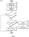
- FIG. 4 is a schematic flow diagram of a method executable by the supervisory controller and/or mobile application of FIG. 1 .
- FIG. 1 schematically illustrates a management system 10 for managing a rechargeable energy storage device 12 in an electric vehicle 15 , which may be partially electric or fully electric.
- the electric vehicle 15 may be a mobile platform, such as, but not limited to, a passenger vehicle, sport utility vehicle, light truck, heavy duty vehicle, ATV, minivan, bus, transit vehicle, bicycle, moving robot, farm implement (e.g. tractor), sports-related equipment (e.g. golf cart), boat, plane and train. It is to be understood that the electric vehicle 15 may take many different forms and have additional components.
- the rechargeable energy storage device 12 includes one or more battery packs (“one or more” omitted henceforth) such as battery pack 14 , each having a plurality of modules 20 .
- the battery pack 14 includes a first, second, third and fourth modules 22 , 24 , 26 , 28 .
- each of the plurality of modules 20 includes one or more respective cells 44 connected for current flow between a first terminal 46 and a second terminal 48 .
- the respective cells 44 may include battery cells having different chemistries, including but not limited to, lithium-ion, lithium-iron, nickel metal hydride and lead acid batteries.
- the number of cells per module and the number of modules per battery pack may be varied based on the application at hand.
- a respective module management unit 30 is embedded in each of the plurality of modules 20 .
- the respective module management unit 30 is configured to measure one or more local parameters, which may pertain to the module as a whole or the respective cells 44 in the module.
- the local parameters may include voltages from each of its respective cells 44 , module current and module temperature.
- the first, second, third and fourth modules 22 , 24 , 26 , 28 respectively incorporate first, second, third and fourth module management units 32 , 34 , 36 , and 38 .
- each of the respective module management units 30 is embedded in the plurality of modules 20 through respective microcircuits 35 .
- the respective microcircuits 35 are an assembly of electronic components, with a core embodied by a microcontroller and including a wireless/CAN communication interface. It is to be understood that the respective microcircuits 35 may be fabricated as a single unit/chip or as multiple combined units/chips.
- the respective microcircuits 35 include an associated memory 37 and an associated processor 39 .
- the respective module management unit 30 may include an integrated electronic controls unit, such as an application-specific integrated circuit (ASIC).
- ASIC application-specific integrated circuit
- a pack communicator 40 may be configured to interface wirelessly with the respective module management unit 30 , via a wireless network 42 , which may be a short-range network or a long-range network.
- the wireless network 42 may be a Wireless Local Area Network (LAN) which links multiple devices using a wireless distribution method, a Wireless Metropolitan Area Networks (MAN) which connects several wireless LANs or a Wireless Wide Area Network (WAN) which covers large areas such as neighboring towns and cities.
- the wireless network 42 may be WIFI or a BluetoothTM connection, defined as being a short-range radio technology (or wireless technology) aimed at simplifying communications among Internet devices and between devices and the Internet.
- BluetoothTM is an open wireless technology standard for transmitting fixed and mobile electronic device data over short distances and creates personal networks operating within the 2.4 GHz band. Other types of connections may be employed.
- the management system 10 includes a supervisory controller C configured for two-way communication with the respective management units 30 .
- the supervisory controller C may be an integral portion of, or a separate module operatively connected to, other controllers of the electric vehicle 15 .
- the supervisory controller C is embedded as a layer in a vehicle integration control module (VICM) of a motor vehicle.
- VICM vehicle integration control module
- the pack communicator 40 is linked or connected to the supervisory controller C via at least one communication BUS 50 , which may be a serial communication BUS in the form of a local area network.
- the local area network may include, but is not limited to, a Controller Area Network (CAN), a Controller Area Network with Flexible Data Rate (CAN-FD).
- CAN Controller Area Network
- CAN-FD Controller Area Network with Flexible Data Rate
- the supervisory controller C includes at least one processor P and at least one memory M (or non-transitory, tangible computer readable storage medium) on which instructions are recorded for executing a method 300 , described below with respect to FIG. 4 .
- the memory M can store executable instruction sets, and the processor P can execute the instruction sets stored in the memory M.
- the management system 10 is characterized by a functional partition between the respective management units 30 and the supervisory controller C.
- the respective management units 30 and the supervisory controller C may perform mutually exclusive functions.
- the respective management unit 30 is configured to receive the pack current from the supervisory controller C, and to measure and monitor respective voltages from each of its respective cells 44 , as well as the temperature of the module and respective cells 44 .
- the respective management unit 30 may determine one or more local parameters, which may include a respective maximum and minimum module voltages, module state of charge, module capacity, cell state of charge, a respective cell state of health if a weaker cell is detected, an allowable module voltage limit and an allowable module current limit.
- the supervisory controller C is configured to receive the one or more local parameters, determine one or more global pack parameters based in part on the one or more local parameters and transmit the one or more global pack parameters back to the respective management units 30 .
- the supervisory controller C is configured to control operation of the rechargeable energy storage device 12 based in part on the one or more global pack parameters.
- the global pack parameters may include a respective power estimation for the battery pack 14 , a cell balancing target, a pack state of charge, a pack capacity and a weak cell state of health monitoring function.
- the supervisory controller C may flag a weak cell (based on data provided by the respective management unit 30 ) and follow up or track its state of health via the weak cell state of health monitoring function.
- the acceptable threshold for defining a “weak” cell may be varied based on the application at hand and may include a predefined minimum capacity.
- the supervisory controller C may control battery charging current and voltage and time based on one or more global parameters, such as pack voltage, temperature and current limits, and state of health of a weaker cell. Additionally, the global pack parameters may be consumed as data by other controllers in the electric vehicle 15 .
- the system 10 includes at least two pack sensors 60 , 62 .
- the pack sensors are configured to detect and transmit a pack voltage, a pack current and/or temperature of the battery pack 14 to the supervisory controller C.
- the respective module management unit 30 may be configured to store local parameters, e.g. module manufacture series numbers, module chemistry profile, module state of charge, module capacity, and module and/or associated cell state of health parameters, in their respective microcontroller memory 37 .
- local parameters e.g. module manufacture series numbers, module chemistry profile, module state of charge, module capacity, and module and/or associated cell state of health parameters
- a diagnostic scan tool or module repair tool may work directly with the respective module management unit 30 for service based on these parameters.
- a refurbished module may be updated with these parameters through the respective module management unit 30 during a module rebuilt, such that when it is reassembled back into the battery pack 14 , it is immediately ready to work with the supervisory controller C without further testing and/or calibration.
- the rechargeable energy storage device 112 includes a first battery pack 114 having a first plurality of modules 120 and a second battery pack 116 having a second plurality of modules 121 .
- Each of the first plurality of modules 120 includes a respective module management unit 130 (embedded through respective microcircuits 135 ) and configured to measure its local parameters.
- a first pack communicator 140 is configured to interface wirelessly with the respective module management unit 130 , via the wireless network 42 .
- each of the second plurality of modules 121 includes a respective module management unit 131 configured to measure its local parameters.
- a second pack communicator 141 is configured to interface wirelessly with the respective module management unit 131 , via the wireless network 42 .
- the first pack communicator 140 and the second pack communicator 141 are linked or connected with a supervisory controller C via a first communication BUS 150 and a second communication BUS 151 .
- the first battery pack 114 and the second battery pack 116 may be connected in parallel or in series.
- the rechargeable energy storage device 212 includes a first battery pack 214 having a first plurality of modules 220 and a second battery pack 216 having a second plurality of modules 221 .
- Each of the first plurality of modules 220 includes a respective module management unit 230 (embedded through respective microcircuits 235 ) configured to measure its local parameters.
- each of the second plurality of modules 221 includes a respective module management unit 231 configured to measure its local parameters.
- a supervisory controller C is linked or connected to each of the first plurality of modules 220 and the second plurality of modules 221 through a shared communication BUS 250 .
- the supervisory controller C may be configured to communicate with a remote server 52 and/or a cloud unit 54 , via the wireless network 42 .
- the remote server 50 may be a private or public source of information maintained by an organization, such as for example, a research institute or a company.
- the cloud unit 54 may include one or more servers hosted on the Internet to store, manage, and process data.
- the supervisory controller C may be configured to receive and transmit wireless communication to the remote server 50 through a mobile application 56 , shown in FIG. 1 .
- the mobile application 56 may be in communication with the supervisory controller C such that it has access to the data in the supervisory controller C.
- the mobile application 56 is physically connected (e.g. wired) to the supervisory controller C.
- the mobile application 56 is embedded in the supervisory controller C.
- the circuitry and components of a mobile application 56 (“apps”) available to those skilled in the art may be employed.
- This data is sent back to the plurality of modules 20 and the respective current limits (I mi ) are replaced by the allowable pack current limit (I pL ).
- the allowable pack current limit (I pL ) is imposed as a new limit for each of the plurality of modules 20 , regardless of the respective current limits (I mi ).
- the respective module management units 30 may be configured to execute cell balancing (for the respective cells in its own module) based on the targeted pack state of charge (SOC target ).
- the respective plurality of modules 20 includes at least four modules.
- the local parameters may include a respective module state of charge (SOC Mi ) and the global pack parameters may include a real-time pack state of charge defined as the minimum module state of charge among the plurality of modules, or as a moving average of the three lowest values of the respective module state of charge when the three lowest values are within a predetermined range, i.e. none of them is largely deviated from the rest.
- the local parameters may include a respective module capacity and the global pack parameters may include a pack capacity defined as the minimum module capacity among the plurality of modules, or as a mean of three lowest values of the respective module capacity when the three lowest values are within a predetermined range.
- Method 300 may be stored on and executable by at least one of the supervisory controller C and the mobile application 56 of FIG. 1 .
- the method 300 need not be applied in the specific order recited herein and may be dynamically executed. Furthermore, it is to be understood that some steps may be eliminated.
- the terms ‘dynamic’ and ‘dynamically’ describe steps or processes that are executed in real-time and are characterized by monitoring or otherwise determining states of parameters and regularly or periodically updating the states of the parameters during execution of a routine or between iterations of execution of the routine.
- the plurality of modules 20 may include multiple sensor arrays configured to measure the respective cell voltages of the respective cells 44 . Sensor arrays available to those skilled in the art may be employed.
- the management system 10 may include at least two pack sensors 60 , 62 configured to generate pack sensor data with respect to the battery pack 14 .
- the supervisory controller C is configured to receive a pack voltage (V pt ) of the battery packs via one of the at least two pack sensors 60 , 62 .
- the supervisory controller C is configured to determine if a difference between the sum of the respective module voltages and the pack voltage is less than a predetermined threshold (T). If so, the method 300 is ended.
- the management system 10 may include a fault detection module 350 selectively executable by the supervisory controller C.
- the supervisory controller C is configured to determine whether an irregularity exists in the pack voltage, via the fault detection module 350 .
- the fault detection module 350 is configured to receive the pack sensor data, analyze the pack sensor data and compare it to a fault algorithm or look up table to determine whether faulty data is generated.
- the fault detection module 350 may include a physical model, a heuristics model, a reinforcement learning and/or machine-learning model.
- the fault detection module 350 may be designed or numerically trained to respond to a set of faults by a respective process.
- the method 300 proceeds to block 310 , where the supervisory controller C is configured to reset a value of the pack voltage as the sum of the respective module voltages.
- the method 300 proceeds to blocks 312 and 314 .
- the supervisory controller C is configured to transmit an alert, for example, to a user of the electric vehicle 15 via a user interface.
- the supervisory controller C may be configured to transmit an alert to the remote server 52 via the wireless network 42 and/or the mobile application 56 . For example, this information may be employed by a fleet supervisor when the electric vehicle 15 is an autonomous vehicle.
- the supervisory controller C is configured to derate or reduce a power rating of the battery pack 14 . If the total power rating of the rechargeable storage device 12 is sufficiently reduced (i.e. reaches a predefined minimum), the supervisory controller C may be configured to switch to an alternative mode of operation, which may be a limp-home mode or other mode restricting energy consumption and/or speed of the electric vehicle 15 .
- the management system 10 provides for focused individual cell monitoring as well as allowing cross-checking for the at least two pack sensors 60 , 62 . Additionally, the management system 10 allows for a wireless management strategy and reconfigurable system. In other words, removal and replacement of one module does not affect other modules. Accordingly, the management system 10 improves the functioning of the electric vehicle 15 .
- each block in the flowchart or block diagrams may represent a module, segment, or portion of code, which comprises one or more executable instructions for implementing the specified logical function(s).
- each block of the block diagrams and/or flowchart illustrations, and combinations of blocks in the block diagrams and/or flowchart illustrations may be implemented by specific purpose hardware-based management systems that perform the specified functions or acts, or combinations of specific purpose hardware and computer instructions.
- the supervisory controller C includes a computer-readable medium (also referred to as a processor-readable medium), including a non-transitory (e.g., tangible) medium that participates in providing data (e.g., instructions) that may be read by a computer (e.g., by a processor of a computer).
- a medium may take many forms, including, but not limited to, non-volatile media and volatile media.
- Non-volatile media may include, for example, optical or magnetic disks and other persistent memory.
- Volatile media may include, for example, dynamic random access memory (DRAM), which may constitute a main memory.
- DRAM dynamic random access memory
- Such instructions may be transmitted by one or more transmission media, including coaxial cables, copper wire and fiber optics, including the wires that comprise a management system bus coupled to a processor of a computer.
- Some forms of computer-readable media include, for example, a floppy disk, a flexible disk, hard disk, magnetic tape, other magnetic media, a CD-ROM, DVD, other optical media, punch cards, paper tape, other physical media with patterns of holes, a RAM, a PROM, an EPROM, a FLASH-EEPROM, other memory chips or cartridges, or other media from which a computer can read.
Landscapes
- Engineering & Computer Science (AREA)
- Power Engineering (AREA)
- Mechanical Engineering (AREA)
- Transportation (AREA)
- Sustainable Development (AREA)
- Sustainable Energy (AREA)
- Life Sciences & Earth Sciences (AREA)
- Manufacturing & Machinery (AREA)
- Chemical & Material Sciences (AREA)
- Chemical Kinetics & Catalysis (AREA)
- Electrochemistry (AREA)
- General Chemical & Material Sciences (AREA)
- Automation & Control Theory (AREA)
- Microelectronics & Electronic Packaging (AREA)
- Secondary Cells (AREA)
Abstract
Description
Claims (19)
SOCtarget=½(SOCmax−SOCmin).
Priority Applications (3)
| Application Number | Priority Date | Filing Date | Title |
|---|---|---|---|
| US16/675,725 US11225169B2 (en) | 2019-11-06 | 2019-11-06 | Management system with supervisory control for rechargeable energy storage device in electric vehicle |
| DE102020126358.9A DE102020126358A1 (en) | 2019-11-06 | 2020-10-08 | MANAGEMENT SYSTEM WITH MONITORING CONTROL FOR RECHARGEABLE ENERGY STORAGE DEVICE IN ELECTRIC VEHICLES |
| CN202011231581.1A CN112786980B (en) | 2019-11-06 | 2020-11-06 | Management system with supervisory control for rechargeable energy storage devices in electric vehicles |
Applications Claiming Priority (1)
| Application Number | Priority Date | Filing Date | Title |
|---|---|---|---|
| US16/675,725 US11225169B2 (en) | 2019-11-06 | 2019-11-06 | Management system with supervisory control for rechargeable energy storage device in electric vehicle |
Publications (2)
| Publication Number | Publication Date |
|---|---|
| US20210129706A1 US20210129706A1 (en) | 2021-05-06 |
| US11225169B2 true US11225169B2 (en) | 2022-01-18 |
Family
ID=75485361
Family Applications (1)
| Application Number | Title | Priority Date | Filing Date |
|---|---|---|---|
| US16/675,725 Active 2040-04-30 US11225169B2 (en) | 2019-11-06 | 2019-11-06 | Management system with supervisory control for rechargeable energy storage device in electric vehicle |
Country Status (3)
| Country | Link |
|---|---|
| US (1) | US11225169B2 (en) |
| CN (1) | CN112786980B (en) |
| DE (1) | DE102020126358A1 (en) |
Cited By (2)
| Publication number | Priority date | Publication date | Assignee | Title |
|---|---|---|---|---|
| US20220352737A1 (en) * | 2021-04-29 | 2022-11-03 | GM Global Technology Operations LLC | Thermal runaway prognosis by detecting abnormal cell voltage and soc degeneration |
| US12438203B2 (en) | 2022-09-07 | 2025-10-07 | GM Global Technology Operations LLC | Distributed battery management for a vehicle |
Families Citing this family (5)
| Publication number | Priority date | Publication date | Assignee | Title |
|---|---|---|---|---|
| DE102021206790A1 (en) | 2021-06-30 | 2023-01-05 | Robert Bosch Gesellschaft mit beschränkter Haftung | battery pack |
| DE102021129775A1 (en) * | 2021-11-16 | 2023-05-17 | Webasto SE | System for providing energy for a vehicle and method for operating such a system |
| US11762028B2 (en) * | 2022-02-11 | 2023-09-19 | GM Global Technology Operations LLC | Resistance estimation of high voltage battery packs during vehicle charging operation |
| CN114670708B (en) * | 2022-04-25 | 2023-06-09 | 松果新能源汽车有限公司 | New energy automobile electric control maintaining system and method |
| CN118232451A (en) * | 2023-09-26 | 2024-06-21 | 比亚迪股份有限公司 | Energy storage systems and power stations |
Citations (5)
| Publication number | Priority date | Publication date | Assignee | Title |
|---|---|---|---|---|
| US6184656B1 (en) * | 1995-06-28 | 2001-02-06 | Aevt, Inc. | Radio frequency energy management system |
| US20120112685A1 (en) * | 2009-04-06 | 2012-05-10 | Myers Motors, LLC | Battery pack manager unit and method for using same to extend the life of a battery pack |
| US20150028816A1 (en) * | 2010-11-02 | 2015-01-29 | Navitas Solutions Inc. | Fault tolerant wireless battery area network for a smart battery management system |
| US20150329003A1 (en) * | 2014-05-15 | 2015-11-19 | Ford Global Technologies, Llc | Electric vehicle operation to manage battery capacity |
| US20170125784A1 (en) * | 2015-11-04 | 2017-05-04 | Johnson Controls Technology Company | Hybrid battery control system architecture systems and methods |
Family Cites Families (3)
| Publication number | Priority date | Publication date | Assignee | Title |
|---|---|---|---|---|
| CA2765945A1 (en) * | 2012-01-30 | 2013-07-30 | Hydro-Quebec | Battery management system for an electric vehicle with energy loss detection |
| CN102738525A (en) * | 2012-06-14 | 2012-10-17 | 沈阳中科正方新能源技术有限公司 | Battery management system of vehicle-mounted lithium power battery |
| US20140277887A1 (en) * | 2013-03-15 | 2014-09-18 | WM GreenTech Automotive Corp. | Method and system for detecting battery type and capacity and automatically adjusting related vehicle parameters |
-
2019
- 2019-11-06 US US16/675,725 patent/US11225169B2/en active Active
-
2020
- 2020-10-08 DE DE102020126358.9A patent/DE102020126358A1/en active Pending
- 2020-11-06 CN CN202011231581.1A patent/CN112786980B/en active Active
Patent Citations (5)
| Publication number | Priority date | Publication date | Assignee | Title |
|---|---|---|---|---|
| US6184656B1 (en) * | 1995-06-28 | 2001-02-06 | Aevt, Inc. | Radio frequency energy management system |
| US20120112685A1 (en) * | 2009-04-06 | 2012-05-10 | Myers Motors, LLC | Battery pack manager unit and method for using same to extend the life of a battery pack |
| US20150028816A1 (en) * | 2010-11-02 | 2015-01-29 | Navitas Solutions Inc. | Fault tolerant wireless battery area network for a smart battery management system |
| US20150329003A1 (en) * | 2014-05-15 | 2015-11-19 | Ford Global Technologies, Llc | Electric vehicle operation to manage battery capacity |
| US20170125784A1 (en) * | 2015-11-04 | 2017-05-04 | Johnson Controls Technology Company | Hybrid battery control system architecture systems and methods |
Cited By (3)
| Publication number | Priority date | Publication date | Assignee | Title |
|---|---|---|---|---|
| US20220352737A1 (en) * | 2021-04-29 | 2022-11-03 | GM Global Technology Operations LLC | Thermal runaway prognosis by detecting abnormal cell voltage and soc degeneration |
| US12352788B2 (en) * | 2021-04-29 | 2025-07-08 | GM Global Technology Operations LLC | Thermal runaway prognosis by detecting abnormal cell voltage and SOC degeneration |
| US12438203B2 (en) | 2022-09-07 | 2025-10-07 | GM Global Technology Operations LLC | Distributed battery management for a vehicle |
Also Published As
| Publication number | Publication date |
|---|---|
| DE102020126358A1 (en) | 2021-05-06 |
| CN112786980B (en) | 2024-08-20 |
| US20210129706A1 (en) | 2021-05-06 |
| CN112786980A (en) | 2021-05-11 |
Similar Documents
| Publication | Publication Date | Title |
|---|---|---|
| US11225169B2 (en) | Management system with supervisory control for rechargeable energy storage device in electric vehicle | |
| KR102928335B1 (en) | Powering electric vehicles | |
| US11065978B2 (en) | Systems, methods, and storage media for adapting machine learning models for optimizing performance of a battery pack | |
| US11555858B2 (en) | Systems, methods, and storage media for predicting a discharge profile of a battery pack | |
| US11325494B2 (en) | Systems, methods, and storage media for determining a target battery charging level for a drive route | |
| US9079505B1 (en) | System and method for management of a fleet of vehicles having an energy storage system | |
| US9878631B2 (en) | System and method for predictive control of an energy storage system for a vehicle | |
| US11084387B2 (en) | Systems, methods, and storage media for arranging a plurality of cells in a vehicle battery pack | |
| US12000895B2 (en) | Method for predicting an aging state of a battery | |
| US11531068B2 (en) | Apparatus and method for tracking electrode capacity | |
| CN117944512A (en) | Intelligent battery system | |
| US11247571B2 (en) | Intelligent energy management system for a vehicle and corresponding method | |
| CN110015111B (en) | Selection of autonomous device charging mode | |
| JP7804111B2 (en) | Battery charging device and battery management device | |
| CN114514436B (en) | Method for adapting anode overvoltage of lithium-ion battery, and method for improving capacity aging state of lithium-ion battery | |
| US20230288216A1 (en) | Optimization of charging profiles for an electric vehicle | |
| CN116848015A (en) | Powering electric vehicles |
Legal Events
| Date | Code | Title | Description |
|---|---|---|---|
| AS | Assignment |
Owner name: GM GLOBAL TECHNOLOGY OPERATIONS LLC, MICHIGAN Free format text: ASSIGNMENT OF ASSIGNORS INTEREST;ASSIGNORS:WANG, YUE-YUN;HAO, LEI;KOCH, BRIAN J.;AND OTHERS;SIGNING DATES FROM 20191101 TO 20191105;REEL/FRAME:050933/0183 |
|
| FEPP | Fee payment procedure |
Free format text: ENTITY STATUS SET TO UNDISCOUNTED (ORIGINAL EVENT CODE: BIG.); ENTITY STATUS OF PATENT OWNER: LARGE ENTITY |
|
| STPP | Information on status: patent application and granting procedure in general |
Free format text: NON FINAL ACTION MAILED |
|
| STPP | Information on status: patent application and granting procedure in general |
Free format text: RESPONSE TO NON-FINAL OFFICE ACTION ENTERED AND FORWARDED TO EXAMINER |
|
| STPP | Information on status: patent application and granting procedure in general |
Free format text: EX PARTE QUAYLE ACTION MAILED |
|
| STPP | Information on status: patent application and granting procedure in general |
Free format text: RESPONSE TO EX PARTE QUAYLE ACTION ENTERED AND FORWARDED TO EXAMINER |
|
| STPP | Information on status: patent application and granting procedure in general |
Free format text: NOTICE OF ALLOWANCE MAILED -- APPLICATION RECEIVED IN OFFICE OF PUBLICATIONS |
|
| STPP | Information on status: patent application and granting procedure in general |
Free format text: PUBLICATIONS -- ISSUE FEE PAYMENT RECEIVED |
|
| STPP | Information on status: patent application and granting procedure in general |
Free format text: PUBLICATIONS -- ISSUE FEE PAYMENT VERIFIED |
|
| STCF | Information on status: patent grant |
Free format text: PATENTED CASE |
|
| MAFP | Maintenance fee payment |
Free format text: PAYMENT OF MAINTENANCE FEE, 4TH YEAR, LARGE ENTITY (ORIGINAL EVENT CODE: M1551); ENTITY STATUS OF PATENT OWNER: LARGE ENTITY Year of fee payment: 4 |