US11225096B2 - Liquid ejection apparatus, winding control method, and computer readable recording medium - Google Patents
Liquid ejection apparatus, winding control method, and computer readable recording medium Download PDFInfo
- Publication number
- US11225096B2 US11225096B2 US16/788,278 US202016788278A US11225096B2 US 11225096 B2 US11225096 B2 US 11225096B2 US 202016788278 A US202016788278 A US 202016788278A US 11225096 B2 US11225096 B2 US 11225096B2
- Authority
- US
- United States
- Prior art keywords
- winding
- unit
- printing medium
- looseness
- rotation
- Prior art date
- Legal status (The legal status is an assumption and is not a legal conclusion. Google has not performed a legal analysis and makes no representation as to the accuracy of the status listed.)
- Expired - Fee Related, expires
Links
Images


Classifications
-
- B—PERFORMING OPERATIONS; TRANSPORTING
- B41—PRINTING; LINING MACHINES; TYPEWRITERS; STAMPS
- B41J—TYPEWRITERS; SELECTIVE PRINTING MECHANISMS, i.e. MECHANISMS PRINTING OTHERWISE THAN FROM A FORME; CORRECTION OF TYPOGRAPHICAL ERRORS
- B41J15/00—Devices or arrangements of selective printing mechanisms, e.g. ink-jet printers or thermal printers, specially adapted for supporting or handling copy material in continuous form, e.g. webs
- B41J15/16—Means for tensioning or winding the web
- B41J15/165—Means for tensioning or winding the web for tensioning continuous copy material by use of redirecting rollers or redirecting nonrevolving guides
-
- B—PERFORMING OPERATIONS; TRANSPORTING
- B41—PRINTING; LINING MACHINES; TYPEWRITERS; STAMPS
- B41J—TYPEWRITERS; SELECTIVE PRINTING MECHANISMS, i.e. MECHANISMS PRINTING OTHERWISE THAN FROM A FORME; CORRECTION OF TYPOGRAPHICAL ERRORS
- B41J13/00—Devices or arrangements of selective printing mechanisms, e.g. ink-jet printers or thermal printers, specially adapted for supporting or handling copy material in short lengths, e.g. sheets
- B41J13/0009—Devices or arrangements of selective printing mechanisms, e.g. ink-jet printers or thermal printers, specially adapted for supporting or handling copy material in short lengths, e.g. sheets control of the transport of the copy material
- B41J13/0027—Devices or arrangements of selective printing mechanisms, e.g. ink-jet printers or thermal printers, specially adapted for supporting or handling copy material in short lengths, e.g. sheets control of the transport of the copy material in the printing section of automatic paper handling systems
-
- B—PERFORMING OPERATIONS; TRANSPORTING
- B41—PRINTING; LINING MACHINES; TYPEWRITERS; STAMPS
- B41J—TYPEWRITERS; SELECTIVE PRINTING MECHANISMS, i.e. MECHANISMS PRINTING OTHERWISE THAN FROM A FORME; CORRECTION OF TYPOGRAPHICAL ERRORS
- B41J13/00—Devices or arrangements of selective printing mechanisms, e.g. ink-jet printers or thermal printers, specially adapted for supporting or handling copy material in short lengths, e.g. sheets
- B41J13/02—Rollers
- B41J13/03—Rollers driven, e.g. feed rollers separate from platen
-
- B—PERFORMING OPERATIONS; TRANSPORTING
- B41—PRINTING; LINING MACHINES; TYPEWRITERS; STAMPS
- B41J—TYPEWRITERS; SELECTIVE PRINTING MECHANISMS, i.e. MECHANISMS PRINTING OTHERWISE THAN FROM A FORME; CORRECTION OF TYPOGRAPHICAL ERRORS
- B41J13/00—Devices or arrangements of selective printing mechanisms, e.g. ink-jet printers or thermal printers, specially adapted for supporting or handling copy material in short lengths, e.g. sheets
- B41J13/26—Registering devices
- B41J13/28—Front lays, stops, or gauges
-
- B—PERFORMING OPERATIONS; TRANSPORTING
- B41—PRINTING; LINING MACHINES; TYPEWRITERS; STAMPS
- B41J—TYPEWRITERS; SELECTIVE PRINTING MECHANISMS, i.e. MECHANISMS PRINTING OTHERWISE THAN FROM A FORME; CORRECTION OF TYPOGRAPHICAL ERRORS
- B41J15/00—Devices or arrangements of selective printing mechanisms, e.g. ink-jet printers or thermal printers, specially adapted for supporting or handling copy material in continuous form, e.g. webs
- B41J15/04—Supporting, feeding, or guiding devices; Mountings for web rolls or spindles
- B41J15/046—Supporting, feeding, or guiding devices; Mountings for web rolls or spindles for the guidance of continuous copy material, e.g. for preventing skewed conveyance of the continuous copy material
-
- B—PERFORMING OPERATIONS; TRANSPORTING
- B41—PRINTING; LINING MACHINES; TYPEWRITERS; STAMPS
- B41J—TYPEWRITERS; SELECTIVE PRINTING MECHANISMS, i.e. MECHANISMS PRINTING OTHERWISE THAN FROM A FORME; CORRECTION OF TYPOGRAPHICAL ERRORS
- B41J15/00—Devices or arrangements of selective printing mechanisms, e.g. ink-jet printers or thermal printers, specially adapted for supporting or handling copy material in continuous form, e.g. webs
- B41J15/16—Means for tensioning or winding the web
-
- B—PERFORMING OPERATIONS; TRANSPORTING
- B41—PRINTING; LINING MACHINES; TYPEWRITERS; STAMPS
- B41J—TYPEWRITERS; SELECTIVE PRINTING MECHANISMS, i.e. MECHANISMS PRINTING OTHERWISE THAN FROM A FORME; CORRECTION OF TYPOGRAPHICAL ERRORS
- B41J29/00—Details of, or accessories for, typewriters or selective printing mechanisms not otherwise provided for
- B41J29/38—Drives, motors, controls or automatic cut-off devices for the entire printing mechanism
-
- B—PERFORMING OPERATIONS; TRANSPORTING
- B65—CONVEYING; PACKING; STORING; HANDLING THIN OR FILAMENTARY MATERIAL
- B65H—HANDLING THIN OR FILAMENTARY MATERIAL, e.g. SHEETS, WEBS, CABLES
- B65H23/00—Registering, tensioning, smoothing or guiding webs
- B65H23/005—Sensing web roll diameter
-
- B—PERFORMING OPERATIONS; TRANSPORTING
- B65—CONVEYING; PACKING; STORING; HANDLING THIN OR FILAMENTARY MATERIAL
- B65H—HANDLING THIN OR FILAMENTARY MATERIAL, e.g. SHEETS, WEBS, CABLES
- B65H23/00—Registering, tensioning, smoothing or guiding webs
- B65H23/02—Registering, tensioning, smoothing or guiding webs transversely
- B65H23/022—Registering, tensioning, smoothing or guiding webs transversely by tentering devices
- B65H23/025—Registering, tensioning, smoothing or guiding webs transversely by tentering devices by rollers
-
- B—PERFORMING OPERATIONS; TRANSPORTING
- B65—CONVEYING; PACKING; STORING; HANDLING THIN OR FILAMENTARY MATERIAL
- B65H—HANDLING THIN OR FILAMENTARY MATERIAL, e.g. SHEETS, WEBS, CABLES
- B65H23/00—Registering, tensioning, smoothing or guiding webs
- B65H23/04—Registering, tensioning, smoothing or guiding webs longitudinally
- B65H23/18—Registering, tensioning, smoothing or guiding webs longitudinally by controlling or regulating the web-advancing mechanism, e.g. mechanism acting on the running web
- B65H23/195—Registering, tensioning, smoothing or guiding webs longitudinally by controlling or regulating the web-advancing mechanism, e.g. mechanism acting on the running web in winding mechanisms or in connection with winding operations
- B65H23/198—Registering, tensioning, smoothing or guiding webs longitudinally by controlling or regulating the web-advancing mechanism, e.g. mechanism acting on the running web in winding mechanisms or in connection with winding operations motor-controlled (Controlling electrical drive motors therefor)
-
- B—PERFORMING OPERATIONS; TRANSPORTING
- B65—CONVEYING; PACKING; STORING; HANDLING THIN OR FILAMENTARY MATERIAL
- B65H—HANDLING THIN OR FILAMENTARY MATERIAL, e.g. SHEETS, WEBS, CABLES
- B65H26/00—Warning or safety devices, e.g. automatic fault detectors, stop-motions, for web-advancing mechanisms
- B65H26/08—Warning or safety devices, e.g. automatic fault detectors, stop-motions, for web-advancing mechanisms responsive to a predetermined diameter
-
- B—PERFORMING OPERATIONS; TRANSPORTING
- B65—CONVEYING; PACKING; STORING; HANDLING THIN OR FILAMENTARY MATERIAL
- B65H—HANDLING THIN OR FILAMENTARY MATERIAL, e.g. SHEETS, WEBS, CABLES
- B65H29/00—Delivering or advancing articles from machines; Advancing articles to or into piles
- B65H29/12—Delivering or advancing articles from machines; Advancing articles to or into piles by means of the nip between two, or between two sets of, moving tapes or bands or rollers
- B65H29/125—Delivering or advancing articles from machines; Advancing articles to or into piles by means of the nip between two, or between two sets of, moving tapes or bands or rollers between two sets of rollers
-
- B—PERFORMING OPERATIONS; TRANSPORTING
- B65—CONVEYING; PACKING; STORING; HANDLING THIN OR FILAMENTARY MATERIAL
- B65H—HANDLING THIN OR FILAMENTARY MATERIAL, e.g. SHEETS, WEBS, CABLES
- B65H2301/00—Handling processes for sheets or webs
- B65H2301/30—Orientation, displacement, position of the handled material
- B65H2301/33—Modifying, selecting, changing orientation
- B65H2301/333—Inverting
- B65H2301/3331—Involving forward reverse transporting means
- B65H2301/33312—Involving forward reverse transporting means forward reverse rollers pairs
-
- B—PERFORMING OPERATIONS; TRANSPORTING
- B65—CONVEYING; PACKING; STORING; HANDLING THIN OR FILAMENTARY MATERIAL
- B65H—HANDLING THIN OR FILAMENTARY MATERIAL, e.g. SHEETS, WEBS, CABLES
- B65H2301/00—Handling processes for sheets or webs
- B65H2301/40—Type of handling process
- B65H2301/44—Moving, forwarding, guiding material
- B65H2301/449—Features of movement or transforming movement of handled material
- B65H2301/4493—Features of movement or transforming movement of handled material intermittent
-
- B—PERFORMING OPERATIONS; TRANSPORTING
- B65—CONVEYING; PACKING; STORING; HANDLING THIN OR FILAMENTARY MATERIAL
- B65H—HANDLING THIN OR FILAMENTARY MATERIAL, e.g. SHEETS, WEBS, CABLES
- B65H2403/00—Power transmission; Driving means
- B65H2403/70—Clutches; Couplings
- B65H2403/73—Couplings
- B65H2403/732—Torque limiters
-
- B—PERFORMING OPERATIONS; TRANSPORTING
- B65—CONVEYING; PACKING; STORING; HANDLING THIN OR FILAMENTARY MATERIAL
- B65H—HANDLING THIN OR FILAMENTARY MATERIAL, e.g. SHEETS, WEBS, CABLES
- B65H2403/00—Power transmission; Driving means
- B65H2403/90—Machine drive
- B65H2403/94—Other features of machine drive
- B65H2403/942—Bidirectional powered handling device
-
- B—PERFORMING OPERATIONS; TRANSPORTING
- B65—CONVEYING; PACKING; STORING; HANDLING THIN OR FILAMENTARY MATERIAL
- B65H—HANDLING THIN OR FILAMENTARY MATERIAL, e.g. SHEETS, WEBS, CABLES
- B65H2404/00—Parts for transporting or guiding the handled material
- B65H2404/10—Rollers
- B65H2404/14—Roller pairs
- B65H2404/145—Roller pairs other
- B65H2404/1452—Roller pairs other web tension
-
- B—PERFORMING OPERATIONS; TRANSPORTING
- B65—CONVEYING; PACKING; STORING; HANDLING THIN OR FILAMENTARY MATERIAL
- B65H—HANDLING THIN OR FILAMENTARY MATERIAL, e.g. SHEETS, WEBS, CABLES
- B65H2553/00—Sensing or detecting means
- B65H2553/51—Encoders, e.g. linear
-
- B—PERFORMING OPERATIONS; TRANSPORTING
- B65—CONVEYING; PACKING; STORING; HANDLING THIN OR FILAMENTARY MATERIAL
- B65H—HANDLING THIN OR FILAMENTARY MATERIAL, e.g. SHEETS, WEBS, CABLES
- B65H2557/00—Means for control not provided for in groups B65H2551/00 - B65H2555/00
- B65H2557/20—Calculating means; Controlling methods
- B65H2557/264—Calculating means; Controlling methods with key characteristics based on closed loop control
- B65H2557/2644—Calculating means; Controlling methods with key characteristics based on closed loop control characterised by PID control
Definitions
- the present invention relates to a liquid ejection apparatus, a winding control method, and a computer readable recording medium.
- An image forming apparatus such as an inkjet printing apparatus, that performs printing by a serial head method on a roll type medium (hereinafter, may also be simply referred to as a medium) that is a printing medium, such as a paper medium or a vinyl chloride medium, wound around a winding core has been known.
- the printed roll type medium is subjected to a winding process based on a predetermined winding method by a winding mechanism in order to prevent the roll type medium from bending, getting dirty, or the like.
- the series winding method is a method of winding a roll type medium by a winding motor with constant winding torque via a mechanism (for example, a torque limiter) that can control torque on a winding shaft.
- the winding mechanism of the series winding method has a simple structure, is available at low cost, and performs winding operation while applying predetermined tension to a printed roll type medium, so that wrinkles are less likely to occur.
- the roll type medium comes in contact with a side plate and is damaged, so that it becomes difficult to perform conveyance”, “image formation on a platen is influenced and image quality is reduced”, and “it becomes difficult to equally wind the right and left sides, so that it becomes difficult to continuously perform winding around a winding shaft.
- Japanese Unexamined Patent Application Publication No. 2016-016946 discloses a printing apparatus that controls ON and OFF of winding operation and controls switching between operation of intentionally forming looseness and operation of performing winding while applying tension at least once, in accordance with a conveying timing. With this configuration, it is possible to reduce a difference between the tension on the right side and the tension on the left side, and it is also possible to obtain tension needed to perform winding.
- a liquid ejection apparatus includes a conveying unit, a winding unit, a printing unit, and a rotation control unit.
- the conveying unit is configured to intermittently convey a printing medium by a predetermined feed amount.
- the winding unit is configured to wind the printing medium conveyed by the conveying unit.
- the printing unit is configured to perform printing on the conveyed printing medium.
- the rotation control unit is configured to control the winding unit to rotate in a winding direction at a predetermined timing after the conveying unit has started to convey the printing medium intermittently, and then cause the winding unit to rotate in a reverse direction opposite to the winding direction.
- FIG. 1 is a diagram illustrating an external appearance of an image forming apparatus according to an embodiment and is a transparent view of main parts;
- FIG. 2 is a top view of a carriage scanning mechanism of the image forming apparatus according to the embodiment
- FIG. 3 is a diagram for explaining a conveying mechanism for conveying a roll type medium
- FIG. 4 is a diagram for explaining a winding paper tube and a peripheral mechanism of the winding paper tube
- FIG. 5 is a block diagram of the image forming apparatus according to the embodiment.
- FIG. 6 is a functional block diagram of a control unit of the image forming apparatus according to the embodiment.
- FIG. 7 is a diagram illustrating a feedback control mode of a main-scanning motor, a conveying motor, a paper feed motor, and a winding motor in the image forming apparatus according to the embodiment;
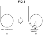
- FIG. 8 is a diagram for explaining a looseness amount of the roll type medium
- FIG. 9 is a diagram for explaining looseness control operation in the image forming apparatus according to the embodiment.
- FIG. 10 is a time chart indicating a timing of a signal in each of units for explaining looseness control in the image forming apparatus according to the embodiment.
- FIG. 11 is a flowchart illustrating the flow of printing operation performed by the image forming apparatus according to the embodiment.
- FIG. 12 is a flowchart illustrating the flow of looseness control operation that is performed prior to initiation of printing by the image forming apparatus according to the embodiment
- FIG. 13 is a flowchart illustrating the flow of the looseness control operation performed by the image forming apparatus according to the embodiment
- FIG. 14 is a flowchart for explaining operation of updating an outer diameter value of the roll type medium that is wound around the winding paper tube during printing;
- FIGS. 15A and 15B are diagrams for explaining a change of the outer diameter value of the roll type medium that is wound around the winding paper tube and a change of an encoder pulse;
- FIG. 16 is a diagram illustrating a change of a voltage value that is supplied from a motor control unit to the winding motor during winding of the roll type medium and after completion of the winding;
- FIG. 17 is a diagram illustrating a change of a pulse number of the encoder pulse that is detected by a winding encoder sensor during winding of the roll type medium and after completion of the winding;
- FIG. 18 is a diagram for explaining the principle of occurrence of looseness of the roll type medium wound by the winding paper tube.
- An embodiment has an object to provide a liquid ejection apparatus, a winding control method, and a computer readable recording medium capable of preventing deformation and skew of a printing medium that is wound in a roll shape and improving printing quality.
- Embodiments of an image forming apparatus as one example of a liquid ejection apparatus, a winding control method, and a computer readable recording medium storing therein a winding control program will be described below with reference to the accompanying drawings.
- FIG. 1 is a perspective view illustrating an external appearance of an image forming apparatus 100 according to an embodiment.
- the image forming apparatus 100 according to the embodiment is what is called an inkjet type image forming apparatus.
- a guide rod 3 and a sub guide rail 4 are extended between both side plates inside a main body 1 .
- a carriage 5 is held by the guide rod 3 and the sub guide rail 4 in such a manner that the carriage 5 can move in a direction of arrow A (in a main-scanning direction).
- a timing belt 11 extended between a drive pulley 9 and a pressure pulley 10 is connected to the carriage 5 .
- the timing belt 11 is driven by a main-scanning motor 8 via the drive pulley 9 , so that the carriage 5 reciprocates in the main-scanning direction A.
- Tension is applied to the timing belt 11 by the pressure pulley 10 . Therefore, the carriage 5 is driven without being loosened.
- FIG. 2 is a plan view of a carriage scanning mechanism.
- a recording medium M is intermittently conveyed along a direction of arrow B (in a sub-scanning direction) below the carriage 5 that reciprocates.
- Recording heads 6 k , 6 c , 6 m , and 6 y eject ink from a plurality of nozzles toward the recording medium M. Accordingly, a predetermined image, character, or the like is printed on the recording medium M.
- “k” indicates black or a key plate
- “c” indicates cyan
- “m” indicates magenta
- y” indicates yellow.
- the ink is one example of liquid.
- water-based ink, ultraviolet (UV)-curable ink, electron beam curable ink, solvent ink, and the like may be used as the ink.
- a cartridge 7 that supplies ink to the recording head 6 and a maintenance mechanism 15 that performs maintenance of the recording head 6 mounted on the carriage 5 are arranged in the main body 1 of the image forming apparatus 100 .
- An encoder sensor 13 is arranged in the carriage 5 .
- the encoder sensor 13 continuously reads an encoder sheet 14 that is extended between both side plates, and detects a position of the carriage 5 in the main-scanning direction. Movement of the carriage 5 is controlled between the two side plates on the basis of the position in the main-scanning direction detected by the encoder sensor 13 .
- an imaging unit 101 that moves together with the carriage 5 is arranged in the carriage 5 .
- the imaging unit 101 reads a color patch of a reference chart and performs a color measurement process for each type of paper.
- FIG. 3 is a diagram for explaining a conveying mechanism for conveying the roll type medium M (one example of a printing medium).
- a paper medium, a vinyl chloride medium, or the like may be used as the roll type medium M that is one example of the printing medium.
- the recording head 6 is mounted on the carriage 5 and printing is performed on a platen 25 (one example of a printing unit).
- the roll type medium M is set in a paper feed unit in a manner of being wound around a paper feed paper tube 52 , and rotationally pulled in a direction of arrow.
- the roll type medium M passes through a printing region on the platen 25 via a conveying roller 35 (one example of a conveying unit) of a conveying unit, and wound around a winding paper tube 44 (one example of a winding unit) that is set in a winding unit.
- the winding unit includes a winding encoder sheet 45 that detects an amount of rotation of the winding paper tube 44 , a winding encoder sensor 39 , and a torque limiter 40 that is drivingly connected to the winding paper tube 44 and that manages an upper limit of torque applied to the roll type medium M. Further, the winding unit includes a winding motor 41 that serves as a drive source when winding and loosening operation is performed, a winding motor encoder sheet 42 that is mounted on a motor shaft to detect a rotation speed and a rotation amount of the motor, and a winding motor encoder sensor 43 .
- the paper feed unit includes a paper feed remaining amount encoder sheet 51 that detects a rotation amount of the paper feed paper tube 52 , a paper feed remaining amount encoder sensor 46 , and a torque limiter 47 that determines tension to be applied to the roll type medium M. Further, the paper feed unit includes a paper feed motor 49 that serves as a drive source for generating tension on the paper feed side, a paper feed motor encoder sheet 48 that is mounted on a motor shaft to detect a rotation speed and a rotation amount of the paper feed motor 49 , and a paper feed motor encoder sensor 50 .
- the paper feed motor 49 is caused to rotate and if a force is applied in a direction opposite to the conveying direction as indicated by an arrow in FIG. 3 , tension is applied to the roll type medium M that is held by the conveying roller 35 and a pressurizing roller 34 , so that the torque limiter 47 starts to slide. Accordingly, it is possible to apply paper feed tension generated by the torque limiter 47 to the roll type medium M.
- the conveying unit includes a conveying motor 37 that serves as a drive source for rotating the conveying roller 35 , and a conveying motor encoder sheet 38 and a conveying motor encoder sensor 36 that are mounted on a shaft of the conveying roller 35 to detect a rotation speed and a rotation amount of the conveying motor 37 .
- the winding paper tube 44 is held by being sandwiched by a flange 54 from right and left sides.
- the winding paper tube 44 rotates when the flange 54 is rotated by the winding motor 41 via the torque limiter 40 .
- the encoder sheet 45 is mounted on a shaft of the flange 54 .
- the winding encoder sensor 39 outputs an encoder pulse corresponding to the rotation speed of the encoder sheet 45 .
- a rotation amount, a rotation position, a rotation speed, and the like of the winding paper tube 44 are calculated based on a pulse number of the encoder pulse.
- FIG. 5 is a block diagram of a main/sub drive control unit 105 of the image forming apparatus 100 .
- the image forming apparatus 100 includes, as the main/sub drive control unit 105 , a control unit 61 (one example of a rotation control unit), a main-scanning unit 62 , a conveying unit 63 , a paper feed unit 64 , and a winding unit 65 .
- the main-scanning unit 62 includes the main-scanning motor 8 , the carriage 5 that is driven by the main-scanning motor 8 , and the recording head 6 and a main-scanning encoder sensor 71 that are mounted on the carriage 5 .
- the conveying unit 63 includes the conveying roller 35 that is driven by the conveying motor 37 , and a conveying encoder sensor 73 that outputs an encoder pulse that varies with rotation of the conveying roller 35 .
- the paper feed unit 64 includes a paper feed paper tube flange 78 that is driven by the paper feed motor 49 , the paper feed motor encoder sensor 50 that outputs an encoder pulse that varies with rotation of the paper feed motor 49 , and the paper feed remaining amount encoder sensor 46 that outputs an encoder pulse that varies with rotation of the paper feed paper tube 52 .
- the winding unit 65 includes a winding paper tube flange 82 that is driven by the winding motor 41 , and the winding motor encoder sensor 43 that outputs an encoder pulse that varies with rotation of the winding motor 41 . Further, the winding unit 65 includes a winding amount encoder sensor 81 that outputs an encoder pulse that varies with rotation of the winding paper tube 44 .
- the winding unit 65 includes the two encoders such as the winding motor encoder sensor 43 that detects rotation of the motor shaft and the winding amount encoder sensor 81 that detects rotation of the paper tube (flange). Therefore, it is possible to obtain two encoder values from the winding unit 65 . Consequently, during looseness control, it is possible to control a looseness amount with high accuracy by performing feedback using an encoder value of the winding amount encoder sensor 81 as an input value and controlling rotation of the winding motor 41 .
- FIG. 6 is a functional block diagram of the control unit 61 .
- the control unit 61 executes a paper feed control program (one example of a winding control program) stored in a memory illustrated in FIG. 5 , and implements each of functions of a printing control unit 85 , a motor control unit 86 , a sensor processing unit 87 , a winding amount detecting unit 88 , and a loosening instruction value calculating unit 89 as illustrated in FIG. 6 .
- a paper feed control program one example of a winding control program
- the printing control unit 85 to the loosening instruction value calculating unit 89 are implemented by software, but a part or all of these units may be implemented by hardware, such as an integrated circuit (IC). Further, the functions implemented by the printing control unit 85 to the loosening instruction value calculating unit 89 may be realized by the single paper feed control program, or it may be possible to cause a different program to execute a part of processes or it may be possible to indirectly perform processes using a different program.
- IC integrated circuit
- the paper feed control program may be provided by being recorded in a computer readable recording medium, such as a compact disk read only memory (CD-ROM) or a flexible disk (FD), in an installable or executable file format.
- the paper feed control program may be provided by being recorded in a computer readable recording medium, such as a CD-recordable (CD-R), a digital versatile disk (DVD), a Blu-ray (registered trademark) disk, or a semiconductor memory.
- the paper feed control program may be provided by being installed via a network, such as the Internet, or may be provided by being incorporated in a ROM or the like in advance in the apparatus.
- the printing control unit 85 gives a drive instruction to each of the main-scanning motor 8 , the conveying motor 37 , the paper feed motor 49 , and the winding motor 41 .
- a direct current (DC) motor may be used as each of the motors 8 , 37 , 49 , and 41 .
- the motor control unit 86 refers to an encoder value detected by the sensor processing unit 87 , and performs speed control and positioning control (position control) on each of the motors 8 , 37 , 49 , and 41 through feedback control as described below.
- the winding amount detecting unit 88 detects an outer diameter of the roll type medium M wound around the winding paper tube 44 , on the basis of a count value of the encoder value that is detected by the sensor processing unit 87 and that is output by the winding motor encoder sensor 43 . Details will be described later.
- the loosening instruction value calculating unit 89 calculates a loosening instruction value that is a rotation pulse number with respect to a loosening direction of the winding motor 41 so as to obtain a desired looseness amount, from the winding outer diameter value that is calculated by the winding amount detecting unit 88 .
- FIG. 7 is a diagram illustrating a feedback control mode of the main-scanning motor 8 , the conveying motor 37 , the paper feed motor 49 , and the winding motor 41 in the image forming apparatus 100 according to the embodiment.
- the motor control unit 86 and the sensor processing unit 87 are realized by software based on the paper feed control program as described above.
- a motor driver 90 each of the motors 8 , 37 , 49 , and 41 , and the encoder sensors 43 , 46 , 50 , 71 , 73 , and 81 are realized by hardware.
- the motor control unit 86 causes a target generating unit 91 to generate target positions and target speeds of the motors 8 , 37 , 49 , and 41 .
- a proportional integral differential (PID) controller 93 generates voltage command values corresponding to the target positions and the target speeds, and supplies the voltage command values to the motor driver 90 .
- the voltage command values are supplied to the motor driver 90 in a signal mode of a pulse width modulation signal (PWM signal).
- PWM signal pulse width modulation signal
- the motor driver 90 causes the motors 8 , 37 , 49 , and 41 to rotate by applying driving voltages corresponding to the voltage command values to the motors 8 , 37 , 49 , and 41 .
- the encoder sensors 43 , 46 , 50 , 71 , 73 , and 81 generate encoder pulses corresponding to the rotation speeds of the motors 8 , 37 , 49 , and 41 , and supply the encoder pulses to the sensor processing unit 87 .
- the sensor processing unit 87 detects current rotation speeds and current rotation positions of the motors 8 , 37 , 49 , and 41 on the basis of the encoder pulse, and feeds them back to the motor control unit 86 .
- the motor control unit 86 causes a comparing unit 92 to detect a difference between each of the target positions and the target speeds generated by the target generating unit 91 and each of the current rotation positions and the current rotation speeds that are fed back, and supplies a differential signal to the PID controller 93 .
- the PID controller 93 generates voltage command values by which the difference indicated by the differential signal, i.e., the difference between each of the target positions and the target speeds generated by the target generating unit 91 and each of the current rotation positions and the current rotation speeds that are fed back, becomes zero (0), and supplies the voltage command value to the motor driver 90 . Accordingly, each of the motors 8 , 37 , 49 , and 41 rotates at the target position and the target speed generated by the target generating unit 91 .
- the looseness amount of the roll type medium M will be described below with reference to FIG. 8 .
- the looseness amount is represented by a length of the roll type medium M and corresponds to a length of an outer circumference of a wound media when described with reference to the winding shaft.
- a state in which the looseness amount is 10 millimeters (mm) is a state in which the roll type medium M wound around the winding paper tube 44 is conveyed by 10 mm from a state in which there is no looseness. This state equals to the state in which the medium is conveyed by 10 mm by the conveying roller 35 from the state in which the medium is not wound.
- FIG. 9 illustrates, at (a), a state in which conveyance is stopped immediately before conveyance by the conveying roller 35 is performed.
- the winding paper tube 44 is subjected to positioning stop control by the winding motor 41 in such a manner that a desired loosening position is maintained.
- positioning control is performed by the feedback control that is described above with reference to FIG. 7 .
- the winding motor encoder sensor 43 detects occurrence of positional deviation from a desired position
- control of returning the rotation position of the winding motor 41 to the desired position is repeated. With this control, the conveying roller 35 keeps stopping at the desired position.
- FIG. 9 illustrates, at (b), a state in which conveyance of the roll type medium M is started and the looseness amount increases. At the start of the conveyance, winding stop control is continued.
- FIG. 9 illustrates, at (c), a state of the roll type medium M that is being conveyed after a lapse of a predetermined time, such as 200 ms, since start of conveyance.
- a predetermined time such as 200 ms
- start of conveyance operation it is possible to prevent inconvenience such as an increase in the tension at the beginning of conveyance. If the winding motor 41 is driven and winding of the roll type medium M is started, extra looseness does not occur, so that the looseness amount is maintained until conveyance of the roll type medium M is stopped.
- FIG. 9 illustrates, at (d), a state in which conveyance of the roll type medium M is stopped and the winding motor 41 continues to perform winding.
- the looseness amount reaches zero (0), so that the conveying roller 35 and the winding paper tube 44 pull the roll type medium M in opposite directions.
- the winding motor 41 does not stop and the torque limiter 40 slides, so that winding is performed at the tension of the torque limiter 40 . Accordingly, it is possible to perform winding tightly and improve winding quality, so that it is possible to accurately detect the outer diameter of the roll type medium M wound around the winding paper tube 44 .
- FIG. 9 illustrates, at (e), a state in which the winding motor 41 is rotated reversely (rotated in a direction opposite to a winding direction of the roll type medium M) in order to intentionally form looseness while conveyance is stopped. After a lapse of a predetermined time since end of conveyance, switching to reverse rotation operation is started.
- the “predetermined time” is a time until winding operation of the roll type medium M around the winding paper tube 44 is completed.
- the output voltage command value (see FIG. 7 ) of the winding motor 41 at the time of sliding the torque limiter 40 as a threshold, and detect termination of winding of the roll type medium M around the winding paper tube 44 when the output voltage command value of the winding motor 41 reaches the threshold. Details will be described later.
- FIG. 9 illustrates, at (e), operation of forming looseness after the roll type medium M is wound around the winding paper tube 44 after conveyance has been stopped.
- the control unit 61 first starts to cause the conveying roller 35 to convey the roll type medium M intermittently ((b) in FIG. 9 ). Then, the control unit 61 controls the winding paper tube 44 to rotate in the winding direction so as to perform winding such that looseness of a printing medium reaches a predetermined level or smaller at a predetermined timing after conveyance has been stated intermittently ((d) in FIG. 9 ). The control unit 61 controls the winding paper tube 44 to rotate in the direction opposite to the winding direction so as to give predetermined looseness to the roll type medium M ((e) in FIG. 9 ). Accordingly, it is possible to prevent deformation and occurrence of skew of the roll type medium M.
- positioning control is continuously performed at the position in accordance with a motor rotation amount (i.e., a rotation amount of the winding paper tube 44 ) that is calculated on the basis of the outer diameter of the roll type medium M wound around the winding paper tube 44 , in order to maintain a constant looseness amount.
- a motor rotation amount i.e., a rotation amount of the winding paper tube 44
- the wound roll type medium M may be wound around the winding paper tube 44 in an eccentric manner.
- eccentricity frequently occurs due to, for example, a setting state of the roll type medium M for each of users, a state of the winding paper tube 44 , or the like.
- it is possible to prevent inconvenience such as a situation in which it becomes difficult to wind the roll type medium M around the winding paper tube 44 due to occurrence of eccentricity.
- FIG. 10 is a time chart indicating a timing of a signal in each of units, for explaining the looseness control.
- FIG. 10 illustrates, at (a), a timing to form an image by performing scanning in the main-scanning direction.
- FIG. 10 illustrates, at (b), a timing of operation of conveying the roll type medium M.
- FIG. 10 illustrates, at (c), a timing to drive winding of the roll type medium M.
- FIG. 10 illustrates, at (d), the looseness amount of the roll type medium M.
- FIG. 10 illustrates, at (e), a medium tension on the platen 25 .
- FIG. 10 illustrates, at (f), a conveying state of the roll type medium M.
- Conveyance of the roll type medium M is started as illustrated at (b) to (f) in FIG. 10 , the roll type medium M is wound up such that there is no looseness as illustrated at (d) and (e) in FIG. 10 before image formation (before printing) is performed as illustrated at (a) in FIG. 10 , predetermined looseness is given again, and printing is performed by the platen 25 with respect to the roll type medium M to which the predetermined looseness is given. With this operation, it is possible to perform printing while increasing flatness on the platen 25 , so that it is possible to perform printing in a preferable manner.
- control unit 61 controls rotation of the winding paper tube 44 such that the torque limiter 40 drivingly connected to the winding paper tube 44 , slides and tension is applied to the roll type medium M.
- FIG. 11 is a flowchart illustrating the flow of printing operation performed by the image forming apparatus according to the embodiment.
- the motor control unit 86 to the loosening instruction value calculating unit 89 as illustrated in FIG. 6 perform looseness control prior to initiation of printing, to thereby form predetermined looseness in the roll type medium M (Step S 1 ), and thereafter start to convey the roll type medium M (Step S 2 ).
- Step S 3 If conveyance of the roll type medium M is started, the motor control unit 86 to the loosening instruction value calculating unit 89 wait for a lapse of a predetermined time, such as 200 msec (Step S 3 ), and thereafter start to wind the roll type medium M (Step S 4 ). If the winding of the roll type medium M is completed, the conveyance is stopped (Step S 5 ).
- a predetermined time such as 200 msec
- control unit 61 starts to rotate the winding paper tube 44 in the winding direction at a predetermined timing after the conveying roller 35 has started to convey the roll type medium M intermittently and before the conveyance is terminated intermittently.
- Step S 6 the motor control unit 86 causes the winding motor 41 to rotate reversely and performs looseness control of intentionally forming looseness in the roll type medium M (Step S 7 ).
- positioning control is continuously performed at a target position in order to maintain a constant looseness amount, in accordance with the motor rotation amount (i.e., the rotation amount of the winding paper tube 44 ) that is calculated on the basis of the outer diameter of the roll type medium M wound around the winding paper tube 44 .
- the motor rotation amount i.e., the rotation amount of the winding paper tube 44
- the printing control unit 85 performs ink ejection control (Step S 8 ) until printing is terminated (Step S 9 ).
- the looseness control operation that is performed prior to initiation of printing and corresponds to Step S 1 in FIG. 11 will be described below with reference to a flowchart in FIG. 12 .
- the flowchart in FIG. 12 indicates a flow of operation of performing looseness control on the basis of the outer diameter of the wound roll type medium M before printing.
- the roll type medium M is attached to the paper feed paper tube 52 and the winding paper tube 44 and set to a state in which printing can be started and winding operation can be performed.
- a current winding state of the wound roll type medium M may be changed if a user exchanges the winding paper tube 44 or the like. Therefore, after an outer diameter value of the roll type medium M wound around the winding paper tube 44 is calculated again, looseness control as described below is performed and printing operation is performed.
- the outer diameter value of the roll type medium M wound around the winding paper tube 44 is calculated when operation of winding the roll type medium M is performed for 5 seconds (sec) and the roll type medium M is conveyed by 50 mm.
- Step S 11 if winding is started (Step S 11 ), the motor control unit 86 , the sensor processing unit 87 , and the winding amount detecting unit 88 control the winding motor 41 such that the roll type medium M is continuously wound around the winding paper tube 44 for 5 seconds, for example (Step S 12 ). Accordingly, the roll type medium M is tightly wound around the winding paper tube 44 . At this time, the looseness amount is 0 mm.
- the winding amount detecting unit 88 holds an encoder value of the winding motor encoder sensor (Step S 13 ).
- the held value is a value indicating a position corresponding to 100 pulses. If the encoder value is acquired as described above, the motor control unit 86 , the sensor processing unit 87 , and the winding amount detecting unit 88 causes the winding motor 41 to stop (Step S 14 ).
- the motor control unit 86 , the sensor processing unit 87 , and the winding amount detecting unit 88 cause the conveying roller 35 to convey the roll type medium M by 50 mm, for example (Step S 15 ). If the roll type medium M has been conveyed by 50 mm (Step S 16 ), the motor control unit 86 , the sensor processing unit 87 , and the winding amount detecting unit 88 controls the winding motor 41 such that the roll type medium M is wound for 5 seconds again (Step S 17 ). If the roll type medium M is continuously wound for 5 seconds (Step S 18 ), the looseness amount reaches 0 mm.
- the winding amount detecting unit 88 holds an encoder value of the winding motor encoder sensor 43 at the time the looseness amount reaches 0 mm (Step S 19 ).
- the held value is a value indicating a position corresponding to 200 pulses. If the encoder value is acquired as described above, the motor control unit 86 , the sensor processing unit 87 , and the winding amount detecting unit 88 causes the winding motor 41 to stop (Step S 20 ).
- the loosening instruction value calculating unit 89 calculates the outer diameter of the roll type medium M wound around the winding paper tube 44 (Step S 21 ).
- the loosening instruction value calculating unit 89 calculates the outer diameter of the roll type medium M using Equation (1) below.
- Outer diameter (mm) of roll type medium M Circumference of roll type medium M/ ⁇ (1)
- the looseness control as described below is performed on the basis of the outer diameter of the roll type medium M calculated as described above.
- Looseness control operation illustrated in the flowchart in FIG. 13 is operation of calculating a loosening instruction value on the basis of the outer diameter value of the wound roll type medium M calculated as described above, and controlling drive of the winding motor 41 by using the loosening instruction value as a target. Through the looseness control operation, appropriate “looseness” is intentionally generated.
- the loosening instruction value calculating unit 89 acquires the calculated outer diameter value of the roll type medium M (Step S 31 ), and calculates a loosening instruction value for controlling the rotation of the winding motor 41 based on Equation (2) below (Step S 32 ).
- Loosening instruction value ( pls ) (gear ratio between gear of winding paper tube 44 and gear of winding motor 41) ⁇ (rotation amount of winding paper tube 44 ( pls )) (2)
- Rotation amount of the winding paper tube 44 ( pls ) is calculated based on Equation (3) below.
- Rotation amount of winding paper tube 44 ( pls ) (number of pulses corresponding to one rotation of encoder sheet 45) ⁇ (looseness amount/circumference of wound roll type medium M ) (3)
- the motor control unit 86 starts to control rotation of the winding motor 41 on the basis of the loosening instruction value calculated as described above (Step S 33 ), and if the winding motor 41 reaches a target position (designated stop position), the motor control unit 86 continues to perform positioning control at a target position (Step S 34 ).
- the looseness control as described above is repeated every time the roll type medium M is conveyed intermittently.
- the winding motor 41 is controlled using the loosening instruction value that is calculated by Equation (2) for the loosening instruction value, but it may be possible to control the winding motor 41 by calculating, as a target position, the rotation amount of the winding paper tube 44 that is calculated using Equation (3) for the rotation amount of the winding paper tube 44 .
- the winding amount detecting unit 88 first holds a current encoder value of the winding motor encoder sensor 43 (Step S 41 ). Subsequently, the motor control unit 86 drives and rotates the main-scanning motor 8 , the conveying motor 37 , the paper feed motor 49 , and the winding motor 41 so as to convey the roll type medium M (Step S 42 ). Further, the printing control unit 85 controls ink ejection of the recording head 6 , and controls printing along the main-scanning direction of the roll type medium M (Step S 43 ).
- the winding amount detecting unit 88 determines whether the roll type medium M has been conveyed by 50 mm or more since previous update of the encoder value of the winding motor encoder sensor 43 .
- the winding amount detecting unit 88 calculates the current outer diameter value of the roll type medium M, and updates the current encoder value of the winding motor encoder sensor 43 (Step S 45 ). Then, if it is determined that the printing is terminated at Step S 46 (YES at Step S 46 ), the process in the flowchart of FIG. 14 is terminated. If it is determined that the printing is continued at Step S 46 , the process returns to Step S 41 , so that the roll type medium M is conveyed by about 50 mm again and the encoder value of the winding motor encoder sensor 43 is detected and updated.
- the outer diameter value of the roll type medium M is repeatedly detected for every certain conveyance distance (every time conveyance is performed intermittently). After printing/conveying operation is repeated a plurality of number of times, and after the roll type medium M is conveyed by a total of 50 mm or more (about 50 mm to 100 mm are acceptable) since previous update, the winding outer diameter value is calculated and updated before next conveying operation.
- FIGS. 15A and 15B are a diagram for explaining a change of the outer diameter value of the roll type medium M that is wound around the winding paper tube 44 and a change of the encoder pulse.
- FIG. 15A illustrates a state in which a small amount of the roll type medium M has been wound around the winding paper tube 44 .
- FIG. 15B illustrates a state in which a large amount of the roll type medium M has been wound around the winding paper tube 44 .
- the amount of change (rotation angle) of the encoder pulse decreases and the number of changing pulses also decreases.
- the loosening instruction value calculating unit 89 calculates an instruction value that is changed in accordance with the outer diameter of the roll type medium M wound around the winding paper tube 44 . Consequently, even if the outer diameter of the roll type medium M wound around the winding paper tube 44 is changed, it is possible to maintain a constant looseness amount as the looseness amount of the roll type medium M. Further, the outer diameter of the roll type medium M can be calculated based on a change of the number of pulses of the encoder pulse detected by the winding encoder sensor 39 .
- completion of winding is detected on the basis of a voltage command value that is supplied to the winding motor 41 whose speed is controlled.
- the motor control unit 86 performs operation of increasing the voltage value to be supplied to the winding motor 41 in order to maintain the rotation speed.
- the increased voltage value and a threshold for detecting the increased voltage value are set and stored in advance. Then, if the winding amount detecting unit 88 continuously detects voltage values that exceed the threshold for a predetermined time, completion of the winding is detected.
- FIG. 16 illustrates the voltage value that is supplied from the motor control unit 86 to the winding motor 41 .
- V 12.5 volts
- the winding motor 41 is driven at a certain voltage below the threshold.
- the voltage value supplied from the motor control unit 86 to the winding motor 41 increases and exceeds the threshold in order to maintain the number of rotations of the winding motor 41 that has stopped rotation.
- the winding amount detecting unit 88 determines that the winding of the roll type medium M is completed.
- completion of the winding is detected based on the voltage value supplied to the winding motor 41 .
- the number of pulses of the encoder pulse detected by the winding encoder sensor 39 gradually increases. However, if the winding is completed, the rotation of the winding paper tube 44 is stopped, so that the number of pulses of the encoder pulse detected by the winding encoder sensor 39 is maintained at a certain level.
- the winding amount detecting unit 88 determines that the winding of the roll type medium M is completed.
- FIG. 18 is a diagram illustrating how looseness of the winding paper tube increases when the present invention is not applied.
- the center of gravity may be inclined. This is because it is difficult to wind the roll type medium M in an ideal condition without eccentricity, such as in the same condition as new, due to the influence of the way to set sheets by a user or a state of the winding paper tube.
- FIG. 18 illustrates, at (a), a state in which winding of the roll type medium M around the winding paper tube 44 by the winding motor 41 is completed. In this state, the winding motor is still driven. Further, the center of gravity is located at a diagonally lower right position in the winding paper tube 44 , for example.
- the roll type medium M is wound again to eliminate the looseness that has occurred, the roll type medium M is wound in the state in which the further looseness has occurred, so that the position of the center of gravity moves to a right position in the winding paper tube 44 as illustrated at (d) in FIG. 18 , for example.
- the printed roll type medium M hangs down to the ground and gets dirty. Further, the roll type medium M may be stuck inside the image forming apparatus or on the ground, so that the printing surface of the platen 25 may be lifted up and come in contact with the carriage 5 , which is a problem.
- the roll type medium M that has loosened due to conveyance is wound up until the looseness is eliminated, and thereafter, the winding motor 41 is controlled to rotate reversely so as to intentionally generate a predetermined amount of looseness such that the looseness amount of the roll type medium M is set to an appropriate looseness amount. Then, the predetermined looseness amount is maintained.
- the predetermined looseness amount is maintained.
- the winding motor encoder sensor 43 for performing feedback control on the winding motor 41 and the winding motor encoder sensor 43 for detecting the rotation amount of the winding paper tube 44 (more precisely, the flange 54 that holds the winding paper tube 44 ) are provided.
- the outer diameter of the wound roll type medium M is calculated from the conveying amount of the roll type medium M and the rotation amount of the winding paper tube 44 .
- the rotation amount of the winding paper tube 44 is determined so as to achieve the predetermined looseness amount, on the basis of the outer diameter of the wound roll type medium M.
- a reverse rotation amount of the winding motor 41 is determined on the basis of the determined rotation amount.
- the winding motor encoder sensor 43 for performing feedback control on the winding motor 41 and the winding motor encoder sensor 43 for detecting the rotation amount of the winding paper tube 44 (more precisely, the flange 54 that holds the winding paper tube 44 ) are provided.
- the outer diameter of the wound roll type medium M is calculated from the conveying amount of the roll type medium M and the rotation amount of the winding paper tube 44 . Further, the rotation amount of the winding paper tube 44 is determined so as to achieve the predetermined looseness amount, on the basis of the outer diameter of the wound roll type medium M. Then, positioning control is performed by the winding motor 41 such that an encoder value of the winding motor encoder sensor 43 reaches a value of a predetermined looseness amount. With this configuration, it is possible to control the rotation angle of the winding paper tube 44 by directly monitoring the rotation angle, so that it is possible to control the looseness amount with high accuracy.
- the rotation speed of the winding motor 41 is controlled so as to maintain a certain looseness amount, in accordance with the outer diameter of the roll type medium M wound around the winding paper tube 44 .
- the rotation speed of the winding motor 41 is controlled so as to maintain a certain looseness amount, in accordance with the outer diameter of the roll type medium M wound around the winding paper tube 44 .
- printing is performed after conveyance of the roll type medium M is completed. If the roll type medium M is made of fabric, it is necessary to perform conveyance by the conveying roller 35 and perform conveyance by winding the roll type medium M while pulling the roll type medium M by the winding side. Therefore, printing is performed after the conveyance of the roll type medium M is completed so that the printing can be performed after winding is certainly performed. With this configuration, it is possible to accurately perform printing even on the roll type medium M made of fabric.
- outer diameter detection and looseness control on the roll type medium M wound around the winding paper tube 44 are performed as initial operation before printing is started. With this configuration, even if the state of the winding paper tube 44 is changed by a user during a job for example, it is possible to generate a desired looseness amount.
- any of the above-described apparatus, devices or units can be implemented as a hardware apparatus, such as a special-purpose circuit or device, or as a hardware/software combination, such as a processor executing a software program.
- any one of the above-described and other methods of the present invention may be embodied in the form of a computer program stored in any kind of storage medium.
- storage mediums include, but are not limited to, flexible disk, hard disk, optical discs, magneto-optical discs, magnetic tapes, nonvolatile memory, semiconductor memory, read-only-memory (ROM), etc.
- any one of the above-described and other methods of the present invention may be implemented by an application specific integrated circuit (ASIC), a digital signal processor (DSP) or a field programmable gate array (FPGA), prepared by interconnecting an appropriate network of conventional component circuits or by a combination thereof with one or more conventional general purpose microprocessors or signal processors programmed accordingly.
- ASIC application specific integrated circuit
- DSP digital signal processor
- FPGA field programmable gate array
- Processing circuitry includes a programmed processor, as a processor includes circuitry.
- a processing circuit also includes devices such as an application specific integrated circuit (ASIC), digital signal processor (DSP), field programmable gate array (FPGA) and conventional circuit components arranged to perform the recited functions.
- ASIC application specific integrated circuit
- DSP digital signal processor
- FPGA field programmable gate array
Landscapes
- Engineering & Computer Science (AREA)
- Mechanical Engineering (AREA)
- Controlling Rewinding, Feeding, Winding, Or Abnormalities Of Webs (AREA)
- Handling Of Continuous Sheets Of Paper (AREA)
Abstract
Description
Outer diameter (mm) of roll type medium M=Circumference of roll type medium M/Π (1)
Loosening instruction value (pls)=(gear ratio between gear of winding
Rotation amount of winding paper tube 44 (pls)=(number of pulses corresponding to one rotation of encoder sheet 45)×(looseness amount/circumference of wound roll type medium M) (3)
Circumference of wound roll type medium M=(outer diameter of wound roll type medium M)×(Π) (4)
Claims (14)
Priority Applications (1)
| Application Number | Priority Date | Filing Date | Title |
|---|---|---|---|
| US17/542,730 US11623462B2 (en) | 2019-02-14 | 2021-12-06 | Liquid ejection apparatus, winding control method, and computer readable recording medium |
Applications Claiming Priority (4)
| Application Number | Priority Date | Filing Date | Title |
|---|---|---|---|
| JP2019024942 | 2019-02-14 | ||
| JP2019-024942 | 2019-02-14 | ||
| JP2019239822A JP7463724B2 (en) | 2019-02-14 | 2019-12-27 | LIQUID EJECTOR, WINDING CONTROL METHOD, AND WINDING CONTROL PROGRAM |
| JP2019-239822 | 2019-12-27 |
Related Child Applications (1)
| Application Number | Title | Priority Date | Filing Date |
|---|---|---|---|
| US17/542,730 Continuation US11623462B2 (en) | 2019-02-14 | 2021-12-06 | Liquid ejection apparatus, winding control method, and computer readable recording medium |
Publications (2)
| Publication Number | Publication Date |
|---|---|
| US20200262221A1 US20200262221A1 (en) | 2020-08-20 |
| US11225096B2 true US11225096B2 (en) | 2022-01-18 |
Family
ID=72041007
Family Applications (2)
| Application Number | Title | Priority Date | Filing Date |
|---|---|---|---|
| US16/788,278 Expired - Fee Related US11225096B2 (en) | 2019-02-14 | 2020-02-11 | Liquid ejection apparatus, winding control method, and computer readable recording medium |
| US17/542,730 Active US11623462B2 (en) | 2019-02-14 | 2021-12-06 | Liquid ejection apparatus, winding control method, and computer readable recording medium |
Family Applications After (1)
| Application Number | Title | Priority Date | Filing Date |
|---|---|---|---|
| US17/542,730 Active US11623462B2 (en) | 2019-02-14 | 2021-12-06 | Liquid ejection apparatus, winding control method, and computer readable recording medium |
Country Status (1)
| Country | Link |
|---|---|
| US (2) | US11225096B2 (en) |
Cited By (1)
| Publication number | Priority date | Publication date | Assignee | Title |
|---|---|---|---|---|
| US12252364B2 (en) * | 2022-02-21 | 2025-03-18 | Seiko Epson Corporation | Printing apparatus and conveyance control method |
Families Citing this family (6)
| Publication number | Priority date | Publication date | Assignee | Title |
|---|---|---|---|---|
| US11396436B2 (en) | 2019-11-21 | 2022-07-26 | Ricoh Company, Ltd. | Conveying device, image forming apparatus incorporating the conveying device, and method of conveying a medium |
| US11801696B2 (en) * | 2019-12-16 | 2023-10-31 | Brother Kogyo Kabushiki Kaisha | Sheet conveyor and image forming system |
| JP7537246B2 (en) | 2020-11-27 | 2024-08-21 | 株式会社リコー | Image forming apparatus, image forming method, and program |
| US12492092B2 (en) * | 2021-07-14 | 2025-12-09 | Hewlett-Packard Development Company, L.P. | Media collecting |
| JP2023173327A (en) | 2022-05-25 | 2023-12-07 | 株式会社リコー | Conveyance device, image forming device, conveyance method and program |
| JP2024079286A (en) | 2022-11-30 | 2024-06-11 | 株式会社リコー | Distance detection device, paper feeder, and image forming device |
Citations (12)
| Publication number | Priority date | Publication date | Assignee | Title |
|---|---|---|---|---|
| JPS61172768A (en) | 1985-01-26 | 1986-08-04 | Olympus Optical Co Ltd | Take-up roller apparatus of printer |
| US5970872A (en) * | 1997-03-14 | 1999-10-26 | Iwatsu Electric Co., Ltd. | Fixing apparatus for a wet-type plate making machine |
| JP2011088366A (en) | 2009-10-23 | 2011-05-06 | Ricoh Co Ltd | Printer and method of controlling the same |
| US20140151491A1 (en) | 2012-12-04 | 2014-06-05 | Ricoh Company, Ltd. | Rolled recording medium conveyance device, image forming apparatus, rolled recording medium conveyance method, and computer program product |
| US20150054898A1 (en) | 2013-08-20 | 2015-02-26 | Ricoh Company, Ltd. | Image forming apparatus |
| US20150178602A1 (en) * | 2013-12-24 | 2015-06-25 | Canon Kabushiki Kaisha | Control apparatus, control method, and non-transitory computer-readable storage medium |
| JP5765562B2 (en) | 2011-05-11 | 2015-08-19 | 株式会社ミマキエンジニアリング | Liquid ejection device |
| JP2016016946A (en) | 2014-07-09 | 2016-02-01 | キヤノン株式会社 | Printing device, printing method and program |
| US20160121626A1 (en) | 2014-11-04 | 2016-05-05 | Ricoh Company, Ltd. | Image forming apparatus |
| US20170151815A1 (en) | 2015-11-30 | 2017-06-01 | Ricoh Company, Ltd. | Image forming apparatus |
| JP2017128024A (en) | 2016-01-20 | 2017-07-27 | ローランドディー.ジー.株式会社 | Ink jet recording device |
| US20180215179A1 (en) * | 2017-01-30 | 2018-08-02 | Seiko Epson Corporation | Transport device and printing apparatus |
Family Cites Families (2)
| Publication number | Priority date | Publication date | Assignee | Title |
|---|---|---|---|---|
| JPH1111449A (en) * | 1997-06-23 | 1999-01-19 | Sato:Kk | Label sticking device |
| JP2014069932A (en) * | 2012-09-28 | 2014-04-21 | Mimaki Engineering Co Ltd | Medium processing device and control method of the same |
-
2020
- 2020-02-11 US US16/788,278 patent/US11225096B2/en not_active Expired - Fee Related
-
2021
- 2021-12-06 US US17/542,730 patent/US11623462B2/en active Active
Patent Citations (12)
| Publication number | Priority date | Publication date | Assignee | Title |
|---|---|---|---|---|
| JPS61172768A (en) | 1985-01-26 | 1986-08-04 | Olympus Optical Co Ltd | Take-up roller apparatus of printer |
| US5970872A (en) * | 1997-03-14 | 1999-10-26 | Iwatsu Electric Co., Ltd. | Fixing apparatus for a wet-type plate making machine |
| JP2011088366A (en) | 2009-10-23 | 2011-05-06 | Ricoh Co Ltd | Printer and method of controlling the same |
| JP5765562B2 (en) | 2011-05-11 | 2015-08-19 | 株式会社ミマキエンジニアリング | Liquid ejection device |
| US20140151491A1 (en) | 2012-12-04 | 2014-06-05 | Ricoh Company, Ltd. | Rolled recording medium conveyance device, image forming apparatus, rolled recording medium conveyance method, and computer program product |
| US20150054898A1 (en) | 2013-08-20 | 2015-02-26 | Ricoh Company, Ltd. | Image forming apparatus |
| US20150178602A1 (en) * | 2013-12-24 | 2015-06-25 | Canon Kabushiki Kaisha | Control apparatus, control method, and non-transitory computer-readable storage medium |
| JP2016016946A (en) | 2014-07-09 | 2016-02-01 | キヤノン株式会社 | Printing device, printing method and program |
| US20160121626A1 (en) | 2014-11-04 | 2016-05-05 | Ricoh Company, Ltd. | Image forming apparatus |
| US20170151815A1 (en) | 2015-11-30 | 2017-06-01 | Ricoh Company, Ltd. | Image forming apparatus |
| JP2017128024A (en) | 2016-01-20 | 2017-07-27 | ローランドディー.ジー.株式会社 | Ink jet recording device |
| US20180215179A1 (en) * | 2017-01-30 | 2018-08-02 | Seiko Epson Corporation | Transport device and printing apparatus |
Cited By (1)
| Publication number | Priority date | Publication date | Assignee | Title |
|---|---|---|---|---|
| US12252364B2 (en) * | 2022-02-21 | 2025-03-18 | Seiko Epson Corporation | Printing apparatus and conveyance control method |
Also Published As
| Publication number | Publication date |
|---|---|
| US20200262221A1 (en) | 2020-08-20 |
| US20220088947A1 (en) | 2022-03-24 |
| US11623462B2 (en) | 2023-04-11 |
Similar Documents
| Publication | Publication Date | Title |
|---|---|---|
| US11623462B2 (en) | Liquid ejection apparatus, winding control method, and computer readable recording medium | |
| US9604449B2 (en) | Image forming apparatus, roll print medium conveyance control method and non-transitory computer readable recording medium | |
| US20090016797A1 (en) | Controlling tension in roll-based print media | |
| JP6710997B2 (en) | Printing device and printing method | |
| US9387703B2 (en) | Image recording apparatus, calibration method, and image recording method | |
| US20100194812A1 (en) | Media advance system for a printer and method of advancing a print medium | |
| US20120092402A1 (en) | Inkjet printing apparatus and carriage control method | |
| JP2019136999A (en) | Liquid discharging device, and printing method | |
| JP6651922B2 (en) | Media feeder | |
| JP5246211B2 (en) | Image recording apparatus and image recording method | |
| US9102176B2 (en) | Image forming apparatus, image forming method, and non-transitory computer-readable storage medium | |
| US10427425B2 (en) | Printer and control method of a printer | |
| CN101854455A (en) | image recording device | |
| US10399368B2 (en) | Printing device and control method of a printing device | |
| JP7463724B2 (en) | LIQUID EJECTOR, WINDING CONTROL METHOD, AND WINDING CONTROL PROGRAM | |
| EP3827998B1 (en) | Image forming apparatus, method for controlling medium supply, and carrier medium | |
| JP5765021B2 (en) | Printer | |
| US20080025781A1 (en) | Printer and method for controlling the printer | |
| US20190232635A1 (en) | Web conveying device | |
| US10118418B2 (en) | Medium feeding apparatus, printing apparatus, and control method of medium feeding apparatus | |
| JP2020158292A (en) | Media transfer device, recording device, and media transfer method | |
| JP7516792B2 (en) | Image forming apparatus and method | |
| US11358404B2 (en) | Printer and method for preventing erroneous interruption of printing | |
| US20170275118A1 (en) | Medium feeding apparatus | |
| US20060182482A1 (en) | Printing apparatus and method of transporting record medium in printing apparatus |
Legal Events
| Date | Code | Title | Description |
|---|---|---|---|
| FEPP | Fee payment procedure |
Free format text: ENTITY STATUS SET TO UNDISCOUNTED (ORIGINAL EVENT CODE: BIG.); ENTITY STATUS OF PATENT OWNER: LARGE ENTITY |
|
| AS | Assignment |
Owner name: RICOH COMPANY, LTD., JAPAN Free format text: ASSIGNMENT OF ASSIGNORS INTEREST;ASSIGNORS:YOKOZAWA, SUGURU;MASUNAGA, SUGURU;OKAMOTO, TAKUYA;SIGNING DATES FROM 20200204 TO 20200207;REEL/FRAME:051811/0062 |
|
| STPP | Information on status: patent application and granting procedure in general |
Free format text: DOCKETED NEW CASE - READY FOR EXAMINATION |
|
| STPP | Information on status: patent application and granting procedure in general |
Free format text: NON FINAL ACTION MAILED |
|
| STPP | Information on status: patent application and granting procedure in general |
Free format text: RESPONSE TO NON-FINAL OFFICE ACTION ENTERED AND FORWARDED TO EXAMINER |
|
| STPP | Information on status: patent application and granting procedure in general |
Free format text: NOTICE OF ALLOWANCE MAILED -- APPLICATION RECEIVED IN OFFICE OF PUBLICATIONS |
|
| STPP | Information on status: patent application and granting procedure in general |
Free format text: PUBLICATIONS -- ISSUE FEE PAYMENT VERIFIED |
|
| STCF | Information on status: patent grant |
Free format text: PATENTED CASE |
|
| FEPP | Fee payment procedure |
Free format text: MAINTENANCE FEE REMINDER MAILED (ORIGINAL EVENT CODE: REM.); ENTITY STATUS OF PATENT OWNER: LARGE ENTITY |
|
| LAPS | Lapse for failure to pay maintenance fees |
Free format text: PATENT EXPIRED FOR FAILURE TO PAY MAINTENANCE FEES (ORIGINAL EVENT CODE: EXP.); ENTITY STATUS OF PATENT OWNER: LARGE ENTITY |
|
| STCH | Information on status: patent discontinuation |
Free format text: PATENT EXPIRED DUE TO NONPAYMENT OF MAINTENANCE FEES UNDER 37 CFR 1.362 |
|
| FP | Lapsed due to failure to pay maintenance fee |
Effective date: 20260118 |