US1122465A - Vulcanizer-press. - Google Patents
Vulcanizer-press. Download PDFInfo
- Publication number
- US1122465A US1122465A US67428612A US1912674286A US1122465A US 1122465 A US1122465 A US 1122465A US 67428612 A US67428612 A US 67428612A US 1912674286 A US1912674286 A US 1912674286A US 1122465 A US1122465 A US 1122465A
- Authority
- US
- United States
- Prior art keywords
- press
- shell
- vulcanizer
- cover
- frame
- Prior art date
- Legal status (The legal status is an assumption and is not a legal conclusion. Google has not performed a legal analysis and makes no representation as to the accuracy of the status listed.)
- Expired - Lifetime
Links
- XLYOFNOQVPJJNP-UHFFFAOYSA-N water Substances O XLYOFNOQVPJJNP-UHFFFAOYSA-N 0.000 description 4
- 244000286663 Ficus elastica Species 0.000 description 2
- RRHGJUQNOFWUDK-UHFFFAOYSA-N Isoprene Chemical compound CC(=C)C=C RRHGJUQNOFWUDK-UHFFFAOYSA-N 0.000 description 2
- 239000000498 cooling water Substances 0.000 description 2
- 238000012856 packing Methods 0.000 description 2
- 229920001195 polyisoprene Polymers 0.000 description 2
- 208000036366 Sensation of pressure Diseases 0.000 description 1
- 230000005494 condensation Effects 0.000 description 1
- 238000009833 condensation Methods 0.000 description 1
- 230000001419 dependent effect Effects 0.000 description 1
Images

Classifications
-
- B—PERFORMING OPERATIONS; TRANSPORTING
- B30—PRESSES
- B30B—PRESSES IN GENERAL
- B30B1/00—Presses, using a press ram, characterised by the features of the drive therefor, pressure being transmitted directly, or through simple thrust or tension members only, to the press ram or platen
- B30B1/10—Presses, using a press ram, characterised by the features of the drive therefor, pressure being transmitted directly, or through simple thrust or tension members only, to the press ram or platen by toggle mechanism
- B30B1/16—Presses, using a press ram, characterised by the features of the drive therefor, pressure being transmitted directly, or through simple thrust or tension members only, to the press ram or platen by toggle mechanism operated by fluid-pressure means
Definitions
- PAUL Bnnn a subject of the Emperor of Austria-Hungary, residing at Sithbneberg. near Berlin, in the German Empire, have invented certain new and useful Improvements in Vulcanizer-lPresses,
- the subject-matterof my invention is an improved vulcanizer-press particularly in-. tended for rulcanizing india-rubber and arranged in such manner that the steam space can be readily charged and emptied.
- the shell of the vulcanizer chamber is arranged so that it can be removed opt of the press without the top:a'nd bottom closures, preferably by swinging it about one column of'the press.
- Atight joint is made at the top and bottom edge of the vulcanizer chamber by a separate press; this is mounted in the pressframe independently of the main press and its piston or ram carries the b0ttom of the vulcanizer chamber.
- the pressure in this press is preferably. made dependent, by
- the press comprises, as usual, a cylinder C in which a piston-or ram R can move up and down,
- the press does not comprise more than three columns.
- a second guide i is provided on the collar b-opposite the guide 12-, and a second shell a can move along this guide.
- Above the place where the guide 2' or'ii is located in its swung-out position is fixedly mounted on the head Z of the press an additional guide 11 along which the shells a and a can be pushed upward.
- Latches- 12 consisting as shown of a handle, a small shaft in a bearing and a crank carrying a proper latch pin, are provided for securing the shells at and a along the guides ii, 2 and n.
- a spring-pressed pin 1 also holds the guides h and i exactly under'the guide n.
- Under the shell (1 which is s'uss pended on the guide n are arranged rails T on which a plate t can be runo'n a truck 10.
- Two plates 2? belong to the machine.
- the shell (1'' is lowered onto this plate t the latter can be seized by the springpressed grippers m and secured to the shell in whose opening it fits.
- Lugs e are provided on the shells a and a.
- a small hydraulic press 9 for raisingand lowering the shell a is ⁇ arranged corresponding to these lugs e, which are engaged by the press.
- the two shells a and a are exactly like one another.
- the press d for closing the vulcanizer chamber is operated with water at a low ids
- the following device shown in Fig. 3 is forfl ocking the bottom of the vulcanizer chajnber in its highest. position into which it .is raised by the press d:
- Two concentric rotatable rings '0 are inserted, between the annular cylinder (5 of the press (Z and the head of the ram or plunger of this press. These rings have projections 39 having slantin faces.
- the head r of the ramv of the plgss has similar projections 9 having sl nting bottom. faces.
- the to faces of the projections 7) then shift on the bottom faces of the projections 9 so that the shell bottom 0 is held fast even when there is no pressure in the press d.
- Steam and cooling water can be supplied to the vulcanizer chamber of the press through pipes, not shown, connected to the head Z of the press.
- the water of condensation which is produced and the cooling water can be led away through a pipe, not shown, detachably connected to the lowest part of the bottom of the vulcanizer chamber.
- the press is operated as follows: One of the plates t is placed on the truck to, the
- the piston of the main press is lowered.
- the shell a or a in the press is thereby liberated and after the spring-pressed pin is which holds the guides h and h in. their position has been withdrawn the collar 6 together with the two guides h and i and the two shells a and a suspended thereon is rotated 180:
- the shell (4 or a removed out of the press is pressed upward by the ram 9 along the guide 71. after the bolt is has been withdraw and the plate 25 has been released fro the grippers m.
- the molds containing the finished articles are then removed from the plate awhich is thereupon charged with fresh molds, for which purpose it may be run on its truck under lifting gear. After the charge in the press has been sufficiently treated the cycle of operations is repeated.
- the purpose of the pressure regulator f is for protecting the packing at the top and bottom edges of the shell a. When the vulcanizer chamber is under pressure this tends to press the bottom 0 downward and to open the joint. Consequently, if the pressure in the press (Z were not gradually increased in .7
- the press may comprise a collar 6 having only one guide It, and may comprise only one shell a; also, one plate 25 only can be used.
- the time requisite for emptying and charging the press is lengthened in this case only by the time required for lifting the shell and lowering it and for clearing the plate 25 and charging it again.
- Some advantages of the press are that charging and emptying are simplified and accelerated and the packing of the vulcanizer chamber is protected.
- the ram and cylinder of the main press can be made very short as they have to compress the mold only and do not have to coiiperate, as in other presses, with the charging and emptying of the press.
- a vulcanizerpress or the like comprising a fixed frame, a shell cover vsecured to said frame, a vertically adjustable shell bot'- tom mounted in the frame below the cover,
- 2-, 3t Yulcanizer press or the like comprise. ing a fixed frame, a shell cover secured to said frame, a vertically adjustable shell bottom mounted in the frame below the cover, a ram adapted to move vertically to said bottom, and a shell hingedly mounted on the frame and adapted to be swung between and into operative and steam tight relation with the cover and bottom, and from under the cover and out of the frame away from the bottom.
- a vulcanizer press or the like comprising a fixed frame, a shell cover secured to said frame, a.
- Vertically adjustable shell bottom mounted in the frame below the cover, a ram adapted to more vertically to said bottom a shell hinged mounted on the frame and adapted to be swung between and into operative and steam tight relation With the cover and bottom, and from under the cover and out of the frame away from the bottom, and a pressure regulator hax ingits low-pressure side in connection with the interior of the said shell and its high-pressure side in connection with the cylinder of the ram.
- a rulcanizer press or the like comprising a fixed frame consisting of vertical col,- umns, a shell cover fixedly mounted on Said columns, a vertically adjustable shell bottom mounted in the frame below the cover, a collar mounted to rotate about one of said columns, a shell between said bottom and cover arranged to. swing from under the cover and mounted on and adapte to slide on said collar, a guide on the out ..le and top of said frame adapted to receive and guide the shell above the levelv of the lower edge of the top, and means for moving and raising said shell alon said collar and guide.
- a vulcanizer press or the like comprising a fixed frame; a shell cover secured to said frame, a vertically adjustable shell bottom mounted in the frame, below the cover, a shell hingedly mounted on the frame and adapted to be swung between and into operative and steam tight relation with the cover and bottom, and from under the cover and eat. of the frame and away from the bottom, a plate adapted to fit loosely into the bottom of said shell, and grippers at the lower end of said shell for holding and releasing said plate.
- a vulcanizer press or the like comprising a fixed frame, , a shell cover secured to said frame, a vertically adjustable shell bottom mounted in the iranre below the cover, a shell hingedly mounted on the frame and ada a to be swung between and into operation and steam tight relation with the cover and bottom and awaytrom the bottom, and rotatable superimposed flat rings below and supporting the shell bottom, the contiguous faces of said rings provided with projections having inclined faces, whereby as said rings are oscillated in opposite directions said shell bottom is held in raised position.
Landscapes
- Engineering & Computer Science (AREA)
- Mechanical Engineering (AREA)
- Heating, Cooling, Or Curing Plastics Or The Like In General (AREA)
Description
,P. BEE-B. VULUANIZER PRESS. APPLICATION FILED JAN. 30, 1912.
1, 1 22,465, Y Patented Dec. 29, 1914.
69557268668: Ezde rzfi";
P. BEER.
VULOANIZER PRESS. APPLICATION FILED JAN. 30. 1912.
1,1 22,465. Patented Dec. 29, 1914 2 SHEETS-SHEET 2.
UM, LEHQH HWh I UNITED STATES PATENT OFFICE.
PAM BEER, 6F SGHfiNEBEBG, NEAB BEBLIN, GERMANY.
V'UICANIZEBFYBESS.
Specification of Letters Patent.
Patented Dec. 29, 191;.
Application filed January 30, 1912. Serial No. 674,288.
To all whom it may concern Be'itknown that 1, PAUL Bnnn, a subject of the Emperor of Austria-Hungary, residing at Sithbneberg. near Berlin, in the German Empire, have invented certain new and useful Improvements in Vulcanizer-lPresses,
' of which the following is a specification.
The subject-matterof my invention is an improved vulcanizer-press particularly in-. tended for rulcanizing india-rubber and arranged in such manner that the steam space can be readily charged and emptied. To
this end, the shell of the vulcanizer chamber is arranged so that it can be removed opt of the press without the top:a'nd bottom closures, preferably by swinging it about one column of'the press.
In order rapidly to empty the vulcanizer chamber moved out of the press it is movable in a vertical guide on the collar by which it is swung about one column of the press, and over theplace which the guide occupies when swung outward is fixedly mounted an additional guide for the shell. After being swung outward the shell can be elevated at this latter guide by means of a press and be lowered again after the charge has been changed.
Atight joint is made at the top and bottom edge of the vulcanizer chamber by a separate press; this is mounted in the pressframe independently of the main press and its piston or ram carries the b0ttom of the vulcanizer chamber. The pressure in this press is preferably. made dependent, by
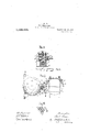
means of a pressure regulator, on the steam pressure, in the interior of the shell in order constantly-to adapt the pressure at the joints to the internal pressure of the shell. One illustrative embodiment of my inven-, tion is represented by way of examplel in the accompanying drawings, wherein Figure 1 is a side elevation, partly in section, showing the press, Fig. 2 a plan view, partly in sectiontaken on the line AB in 1, Fig. 3 a vertical section,
enlarged, showing the separate press for closing the \nlcanizer chamber. Fig. 4 a side elevation showing partof the press shown in Fig. 3. Fig- 5 is a fragmentary h view showing on an enlarged scale the grippers. v Referring to the drawings, the press comprises, as usual, a cylinder C in which a piston-or ram R can move up and down,
and with-which the head lot the pressis connected by columns P constituting the frame of the press. Between the head Z of the press and the cylinder is the vulcanizmg chamber whose cover is formed by the head I of the press, and whose shell a is independent of both the cover Z and the bottom 0. This bottom surrounds the end plate R of the piston or ram and a tight Joint is made between it and the piston R by a stuilingbox c, as clearly shown. It rests on the head r of the ram of another hydraulic i press (I which is mounted independently of the main press in the frame of the in press on the cylinder C. The shell 'movable up and down in a guide It onlthecollar 1) which is revoluble on ball-bearings I) about one column of the press. Pref-- erably, the press does not comprise more than three columns. A second guide i is provided on the collar b-opposite the guide 12-, and a second shell a can move along this guide. Above the place where the guide 2' or'ii is located in its swung-out position is fixedly mounted on the head Z of the press an additional guide 11 along which the shells a and a can be pushed upward. Latches- 12 consisting as shown of a handle, a small shaft in a bearing and a crank carrying a proper latch pin, are provided for securing the shells at and a along the guides ii, 2 and n. A spring-pressed pin 1: also holds the guides h and i exactly under'the guide n. Under the shell (1 which is s'uss pended on the guide n are arranged rails T on which a plate t can be runo'n a truck 10.
Two plates 2? belong to the machine. Whenthe shell (1'' is lowered onto this plate t the latter can be seized by the springpressed grippers m and secured to the shell in whose opening it fits. Lugs e are provided on the shells a and a. A small hydraulic press 9 for raisingand lowering the shell a is\arranged corresponding to these lugs e, which are engaged by the press. The two shells a and a are exactly like one another.
The press d for closing the vulcanizer chamber is operated with water at a low ids The following device shown in Fig. 3 is forfl ocking the bottom of the vulcanizer chajnber in its highest. position into which it .is raised by the press d: Two concentric rotatable rings '0 are inserted, between the annular cylinder (5 of the press (Z and the head of the ram or plunger of this press. These rings have projections 39 having slantin faces. The head r of the ramv of the plgss has similar projections 9 having sl nting bottom. faces. In the ram of the pr ss d is journaled the pivot s of a lever 8 through whose slot-like openings are passed two bblts s" eachof which is secured to the two rings. By rocking the lever 8 the rings 0 can be displaced relatively to the llead r of the plunger of the press (2.
The to faces of the projections 7) then shift on the bottom faces of the projections 9 so that the shell bottom 0 is held fast even when there is no pressure in the press d. Steam and cooling water can be supplied to the vulcanizer chamber of the press through pipes, not shown, connected to the head Z of the press. The water of condensation which is produced and the cooling water can be led away through a pipe, not shown, detachably connected to the lowest part of the bottom of the vulcanizer chamber.
The press is operated as follows: One of the plates t is placed on the truck to, the
molds containing the india-rubber'pieces to be pressed are placed thereon, and the truck is run under a shell a or a carried by the guide a. The shell is lowered by means of the press 9, after the bolt is has been with drawn, so that the plate 2, with the molds is inclosed by it- The plate 25 is then secured by the grippers mto the shell, said grippers, as shown in Fig. 5, comprising simple latches having fastened to them handles movable in small stufiing boxes and two loose spring pressed pins. The shell a in the press is now relieved from the internal steam pressure and from the pressure of thepress (Z. By roclring the'lever s the lock formed by the rings 0 is released. The piston of the main press is lowered. The shell a or a in the press is thereby liberated and after the spring-pressed pin is which holds the guides h and h in. their position has been withdrawn the collar 6 together with the two guides h and i and the two shells a and a suspended thereon is rotated 180:
Water under pressure is then admitted into,
a? is then cut off. The piston of the main" Dress is then driven and steam is admitted pressure of water in the press d accordi g v to the increase of pressure in the vulcanizer chamber of the press for the time being.
The shell (4 or a removed out of the press is pressed upward by the ram 9 along the guide 71. after the bolt is has been withdraw and the plate 25 has been released fro the grippers m. The molds containing the finished articles are then removed from the plate awhich is thereupon charged with fresh molds, for which purpose it may be run on its truck under lifting gear. After the charge in the press has been sufficiently treated the cycle of operations is repeated. The purpose of the pressure regulator f is for protecting the packing at the top and bottom edges of the shell a. When the vulcanizer chamber is under pressure this tends to press the bottom 0 downward and to open the joint. Consequently, if the pressure in the press (Z were not gradually increased in .7
proportion with the steam pressure, the pres sure would have to be so great from the first that it could both oppose the action of the steam pressure on the bottom 0 and also form tight joints at the top and bottom edges of the shell .1. The packingsat these places would, however, be injured, because they would be exposed to the full pressure when there was no counter pressure in the vulcanizer chamber.
Without departing from the invention the press may comprise a collar 6 having only one guide It, and may comprise only one shell a; also, one plate 25 only can be used. The time requisite for emptying and charging the press is lengthened in this case only by the time required for lifting the shell and lowering it and for clearing the plate 25 and charging it again.
Some advantages of the press are that charging and emptying are simplified and accelerated and the packing of the vulcanizer chamber is protected. In addition, the ram and cylinder of the main press can be made very short as they have to compress the mold only and do not have to coiiperate, as in other presses, with the charging and emptying of the press. a
While I have described my invention as applied to a vulcanizer or vulcanizing chamber, it will be readily seen that the scope of the invention is such, that it'mayjbe readilyapplied to other purposes'not specifically I used for vulcanizing, and I so contemplate applying the same. 1
T claim:
1. A vulcanizerpress or the like comprising a fixed frame, a shell cover vsecured to said frame, a vertically adjustable shell bot'- tom mounted in the frame below the cover,
memes and a shell hingedly mounted on the frame and adapted to he swung between and into operative and steam tight relation with the cover and bottom, and from under the cover and out of the frame and away from the bottom.
2-, 3t Yulcanizer press or the like comprise. ing a fixed frame, a shell cover secured to said frame, a vertically adjustable shell bottom mounted in the frame below the cover, a ram adapted to move vertically to said bottom, and a shell hingedly mounted on the frame and adapted to be swung between and into operative and steam tight relation with the cover and bottom, and from under the cover and out of the frame away from the bottom.
3. A vulcanizer press or the like comprising a fixed frame, a shell cover secured to said frame, a. Vertically adjustable shell bottom mounted in the frame below the cover, a ram adapted to more vertically to said bottom a shell hinged mounted on the frame and adapted to be swung between and into operative and steam tight relation With the cover and bottom, and from under the cover and out of the frame away from the bottom, and a pressure regulator hax ingits low-pressure side in connection with the interior of the said shell and its high-pressure side in connection with the cylinder of the ram.
4. A rulcanizer press or the like compris: ing a fixed frame consisting of vertical col,- umns, a shell cover fixedly mounted on Said columns, a vertically adjustable shell bottom mounted in the frame below the cover, a collar mounted to rotate about one of said columns, a shell between said bottom and cover arranged to. swing from under the cover and mounted on and adapte to slide on said collar, a guide on the out ..le and top of said frame adapted to receive and guide the shell above the levelv of the lower edge of the top, and means for moving and raising said shell alon said collar and guide.
A vulcanizer press or the like compris ing a fixed frame; a shell cover secured to said frame, a vertically adjustable shell bottom mounted in the frame, below the cover, a shell hingedly mounted on the frame and adapted to be swung between and into operative and steam tight relation with the cover and bottom, and from under the cover and eat. of the frame and away from the bottom, a plate adapted to fit loosely into the bottom of said shell, and grippers at the lower end of said shell for holding and releasing said plate.
s. A vulcanizer press or the like compris ing a fixed frame, ,a shell cover secured to said frame, a vertically adjustable shell bottom mounted in the iranre below the cover, a shell hingedly mounted on the frame and ada a to be swung between and into operation and steam tight relation with the cover and bottom and awaytrom the bottom, and rotatable superimposed flat rings below and supporting the shell bottom, the contiguous faces of said rings provided with projections having inclined faces, whereby as said rings are oscillated in opposite directions said shell bottom is held in raised position.
in testimony whereof I afiix my signature in presence of two witnesses.
ING. PAUL BEER itnesses:
FELIX IYEUEAUER,
RICHARD KAPPEL.
Priority Applications (1)
| Application Number | Priority Date | Filing Date | Title |
|---|---|---|---|
| US67428612A US1122465A (en) | 1912-01-30 | 1912-01-30 | Vulcanizer-press. |
Applications Claiming Priority (1)
| Application Number | Priority Date | Filing Date | Title |
|---|---|---|---|
| US67428612A US1122465A (en) | 1912-01-30 | 1912-01-30 | Vulcanizer-press. |
Publications (1)
| Publication Number | Publication Date |
|---|---|
| US1122465A true US1122465A (en) | 1914-12-29 |
Family
ID=3190625
Family Applications (1)
| Application Number | Title | Priority Date | Filing Date |
|---|---|---|---|
| US67428612A Expired - Lifetime US1122465A (en) | 1912-01-30 | 1912-01-30 | Vulcanizer-press. |
Country Status (1)
| Country | Link |
|---|---|
| US (1) | US1122465A (en) |
-
1912
- 1912-01-30 US US67428612A patent/US1122465A/en not_active Expired - Lifetime
Similar Documents
| Publication | Publication Date | Title |
|---|---|---|
| US2983953A (en) | Press with power device for opening and handling multiple section molds | |
| US1122465A (en) | Vulcanizer-press. | |
| US2579176A (en) | Press | |
| US2431048A (en) | Mold press | |
| US1919070A (en) | Hydraulic press | |
| US2090415A (en) | Method of and apparatus for manufacturing wooden vessels | |
| US2239248A (en) | Press assembly | |
| US1169559A (en) | Press. | |
| US3343218A (en) | Mold mounting structure for press | |
| US2324991A (en) | Molding apparatus | |
| US2226326A (en) | Molding machine | |
| US1412029A (en) | Wine press | |
| US1750424A (en) | Molding apparatus | |
| US1646568A (en) | Press | |
| GB507034A (en) | Process and apparatus for finishing boxes having a hinged lid | |
| US748138A (en) | Press for oleaginous substances. | |
| US857123A (en) | Press for forming internal grooves in paper vessels. | |
| US1400913A (en) | Manufacture of hard-rubber battery-jars and similar articles | |
| US868996A (en) | Pulp-shaping machine. | |
| US668943A (en) | Machine for making paper pails. | |
| US2289671A (en) | Press for the manufacture of plastic articles | |
| US1146168A (en) | Tile-making machine. | |
| US1375831A (en) | Press for moldable compounds | |
| US1517128A (en) | Concrete-block-making machine | |
| US797122A (en) | Filter-pulp-packing machine. |