US11223781B2 - Image-capturing apparatus and image-capturing method - Google Patents
Image-capturing apparatus and image-capturing method Download PDFInfo
- Publication number
- US11223781B2 US11223781B2 US16/638,505 US201816638505A US11223781B2 US 11223781 B2 US11223781 B2 US 11223781B2 US 201816638505 A US201816638505 A US 201816638505A US 11223781 B2 US11223781 B2 US 11223781B2
- Authority
- US
- United States
- Prior art keywords
- light
- image
- capturing apparatus
- stop
- opening portion
- Prior art date
- Legal status (The legal status is an assumption and is not a legal conclusion. Google has not performed a legal analysis and makes no representation as to the accuracy of the status listed.)
- Expired - Fee Related
Links
Images


Classifications
-
- H04N5/238—
-
- G—PHYSICS
- G03—PHOTOGRAPHY; CINEMATOGRAPHY; ANALOGOUS TECHNIQUES USING WAVES OTHER THAN OPTICAL WAVES; ELECTROGRAPHY; HOLOGRAPHY
- G03B—APPARATUS OR ARRANGEMENTS FOR TAKING PHOTOGRAPHS OR FOR PROJECTING OR VIEWING THEM; APPARATUS OR ARRANGEMENTS EMPLOYING ANALOGOUS TECHNIQUES USING WAVES OTHER THAN OPTICAL WAVES; ACCESSORIES THEREFOR
- G03B11/00—Filters or other obturators specially adapted for photographic purposes
-
- H—ELECTRICITY
- H04—ELECTRIC COMMUNICATION TECHNIQUE
- H04N—PICTORIAL COMMUNICATION, e.g. TELEVISION
- H04N23/00—Cameras or camera modules comprising electronic image sensors; Control thereof
- H04N23/70—Circuitry for compensating brightness variation in the scene
- H04N23/75—Circuitry for compensating brightness variation in the scene by influencing optical camera components
-
- G—PHYSICS
- G02—OPTICS
- G02B—OPTICAL ELEMENTS, SYSTEMS OR APPARATUS
- G02B5/00—Optical elements other than lenses
- G02B5/005—Diaphragms
-
- G—PHYSICS
- G02—OPTICS
- G02B—OPTICAL ELEMENTS, SYSTEMS OR APPARATUS
- G02B7/00—Mountings, adjusting means, or light-tight connections, for optical elements
- G02B7/28—Systems for automatic generation of focusing signals
- G02B7/36—Systems for automatic generation of focusing signals using image sharpness techniques, e.g. image processing techniques for generating autofocus signals
- G02B7/38—Systems for automatic generation of focusing signals using image sharpness techniques, e.g. image processing techniques for generating autofocus signals measured at different points on the optical axis, e.g. focussing on two or more planes and comparing image data
-
- G—PHYSICS
- G03—PHOTOGRAPHY; CINEMATOGRAPHY; ANALOGOUS TECHNIQUES USING WAVES OTHER THAN OPTICAL WAVES; ELECTROGRAPHY; HOLOGRAPHY
- G03B—APPARATUS OR ARRANGEMENTS FOR TAKING PHOTOGRAPHS OR FOR PROJECTING OR VIEWING THEM; APPARATUS OR ARRANGEMENTS EMPLOYING ANALOGOUS TECHNIQUES USING WAVES OTHER THAN OPTICAL WAVES; ACCESSORIES THEREFOR
- G03B13/00—Viewfinders; Focusing aids for cameras; Means for focusing for cameras; Autofocus systems for cameras
- G03B13/32—Means for focusing
- G03B13/34—Power focusing
- G03B13/36—Autofocus systems
-
- G—PHYSICS
- G03—PHOTOGRAPHY; CINEMATOGRAPHY; ANALOGOUS TECHNIQUES USING WAVES OTHER THAN OPTICAL WAVES; ELECTROGRAPHY; HOLOGRAPHY
- G03B—APPARATUS OR ARRANGEMENTS FOR TAKING PHOTOGRAPHS OR FOR PROJECTING OR VIEWING THEM; APPARATUS OR ARRANGEMENTS EMPLOYING ANALOGOUS TECHNIQUES USING WAVES OTHER THAN OPTICAL WAVES; ACCESSORIES THEREFOR
- G03B33/00—Colour photography, other than mere exposure or projection of a colour film
- G03B33/02—Colour photography, other than mere exposure or projection of a colour film by two-colour separation records, e.g. red-aspect and white complete records; using Land effect
-
- G—PHYSICS
- G03—PHOTOGRAPHY; CINEMATOGRAPHY; ANALOGOUS TECHNIQUES USING WAVES OTHER THAN OPTICAL WAVES; ELECTROGRAPHY; HOLOGRAPHY
- G03B—APPARATUS OR ARRANGEMENTS FOR TAKING PHOTOGRAPHS OR FOR PROJECTING OR VIEWING THEM; APPARATUS OR ARRANGEMENTS EMPLOYING ANALOGOUS TECHNIQUES USING WAVES OTHER THAN OPTICAL WAVES; ACCESSORIES THEREFOR
- G03B7/00—Control of exposure by setting shutters, diaphragms or filters, separately or conjointly
-
- G—PHYSICS
- G03—PHOTOGRAPHY; CINEMATOGRAPHY; ANALOGOUS TECHNIQUES USING WAVES OTHER THAN OPTICAL WAVES; ELECTROGRAPHY; HOLOGRAPHY
- G03B—APPARATUS OR ARRANGEMENTS FOR TAKING PHOTOGRAPHS OR FOR PROJECTING OR VIEWING THEM; APPARATUS OR ARRANGEMENTS EMPLOYING ANALOGOUS TECHNIQUES USING WAVES OTHER THAN OPTICAL WAVES; ACCESSORIES THEREFOR
- G03B9/00—Exposure-making shutters; Diaphragms
- G03B9/02—Diaphragms
-
- H—ELECTRICITY
- H04—ELECTRIC COMMUNICATION TECHNIQUE
- H04N—PICTORIAL COMMUNICATION, e.g. TELEVISION
- H04N23/00—Cameras or camera modules comprising electronic image sensors; Control thereof
- H04N23/20—Cameras or camera modules comprising electronic image sensors; Control thereof for generating image signals from infrared radiation only
-
- H—ELECTRICITY
- H04—ELECTRIC COMMUNICATION TECHNIQUE
- H04N—PICTORIAL COMMUNICATION, e.g. TELEVISION
- H04N23/00—Cameras or camera modules comprising electronic image sensors; Control thereof
- H04N23/50—Constructional details
- H04N23/55—Optical parts specially adapted for electronic image sensors; Mounting thereof
Definitions
- the present technology relates to an image-capturing apparatus, an image-capturing method, and a program that make it possible to perform image-capturing with pieces of light of different wavelengths.
- Patent Literature 1 Japanese Patent Application Laid-open No. 2012-22308
- Patent Literature 1 it is not possible to set an opening diameter of a stop to a value not greater than a certain value, since the structured opening will be affected if the value of the opening diameter is not greater than the certain value. Further, an infrared aperture has a constant value due to the structured opening.
- the image-capturing apparatus when the image-capturing apparatus is installed in a movable object such as an auto, it is not possible to reduce an amount of visible light and an amount of infrared light sufficiently upon performing image-capturing in light of very high intensity such as in sunlight. Conversely, it is not possible to open an infrared stop to increase the amount of light in light of low intensity such as at night.
- an object of the present technology to provide an image-capturing apparatus, an image-capturing method, and a program that are suitable to perform image-capturing with pieces of light of different wavelengths.
- an image-capturing apparatus includes an imaging element, an optical element, a first stop, a second stop, and a stop controller.
- the imaging element performs wavelength separation on incident light to obtain first light of a first wavelength and second light of a second wavelength, and photoelectrically converts the first light and the second light, the first light and the second light being included in the incident light.
- the optical element collects light in the image-capturing apparatus.
- the first stop is provided in a path of the incident light, and includes a first opening portion and a first blocking portion, the first opening portion being a portion through which the first light and the second light are transmitted, the first blocking portion being a portion that blocks the first light and through which the second light is transmitted.
- the second stop is provided in the path of the incident light, and includes a second opening portion and a second blocking portion, the second opening portion being a portion through which the first light and the second light are transmitted, the second blocking portion being a portion that blocks the second light and through which the first light is transmitted.
- the stop controller separately controls a size of the first opening portion and a size of the second opening portion.
- This configuration makes it possible to separately control the first stop and the second stop, and thus to discretionally adjust amounts of the first light and the second light that enter the imaging element.
- the first wavelength may be a wavelength of infrared light
- the second wavelength may be a wavelength of visible light
- This configuration makes it possible to separately adjust amounts of infrared light and visible light that enter the imaging element.
- the first opening portion and the second opening portion may be shifted from each other in a direction orthogonal to a direction of an optical axis of the incident light.
- an image of the subject that is captured with the first light (the first image) and an image of the subject that is captured with the second light (the second image) are shifted from each other in a captured image.
- At least one of a center of the first opening portion or a center of the second opening portion may coincide with a center of an optical axis of the incident light.
- an image of light whose amount is reduced by a stop having an opening-portion center that coincides with a center of an optical axis of the incident light is not shifted due to focusing, the light being the first light or the second light, and this makes it possible to prevent the visibility of the image from being affected.
- the image-capturing apparatus may further include a distance-to-subject calculator that calculates a distance to a subject using a captured image that is captured by the imaging element, the captured image including a first image that is an image of the first light, and a second image that is an image of the second light.
- a distance-to-subject calculator that calculates a distance to a subject using a captured image that is captured by the imaging element, the captured image including a first image that is an image of the first light, and a second image that is an image of the second light.
- the distance-to-subject calculator can calculate the distance to a subject using the captured image including the first image and the second image, since the first opening portion and the second opening portion are shifted from each other in the direction orthogonal to the direction of the optical axis of the incident light.
- the distance-to-subject calculator may calculate the distance to a subject using an amount of a shift between the first image and the second image in the captured image.
- the distance-to-subject calculator can calculate the distance to a subject using the amount of the shift between the first image and the second image and using a focal length of the image-capturing apparatus.
- the first wavelength may be a wavelength of infrared light
- the second wavelength may be a wavelength of visible light
- the center of the first opening portion may be shifted from the center of the optical axis of the incident light
- the center of the second opening portion may coincide with the center of the optical axis of the incident light.
- an image of visible light in a captured image is not shifted due to the position of an opening portion (the second opening portion) of a stop, whereas an image of infrared light in the captured image is shifted due to the position of an opening portion (the first opening portion) of a stop depending on focusing.
- This makes it possible to exert an effect due to a distance to a subject on the image of infrared light without affecting the image of visible light.
- the imaging element may perform wavelength separation for the first wavelength and the second wavelength in a direction orthogonal to an optical axis of the incident light.
- the imaging element may perform wavelength separation for the first wavelength and the second wavelength in a direction parallel to an optical axis of the incident light.
- the image-capturing apparatus may further include an optical element controller that controls the optical element according to the distance to a subject.
- This configuration makes it possible to cause the image-capturing apparatus to be focused on a subject, using the distance to a subject that is calculated using the amount of the shift between the first image and the second image.
- the image-capturing apparatus may further include a distance image generator that generates a distance image from the distance to a subject.
- This configuration enables the image-capturing apparatus to generate a distance image including distance information.
- the image-capturing apparatus may further include a defocusing processing section that performs defocusing processing using an amount of a shift between a first image and a second image in a captured image that is captured by the imaging element, the captured image including the first image and the second image, the first image being an image of the first light, the second image being an image of the second light.
- a defocusing processing section that performs defocusing processing using an amount of a shift between a first image and a second image in a captured image that is captured by the imaging element, the captured image including the first image and the second image, the first image being an image of the first light, the second image being an image of the second light.
- This configuration makes it possible to perform defocusing processing on a captured image using the amount of the shift between the first image and the second image.
- the stop controller may control a size of the first opening portion and a size of the second opening portion according to an amount of the first light entering the imaging element and an amount of the second light entering the imaging element.
- the stop controller may control a distance between a center of the first opening portion and a center of the second opening portion in a direction orthogonal to an optical axis of the incident light according to a movement speed of the image-capturing apparatus.
- a program for controlling an image-capturing apparatus, the image-capturing apparatus including an imaging element that performs wavelength separation on incident light to obtain first light of a first wavelength and second light of a second wavelength, and photoelectrically converts the first light and the second light, the first light and the second light being included in the incident light; an optical element that collects light in the image-capturing apparatus; a first stop that is provided in a path of the incident light, and includes a first opening portion and a first blocking portion, the first opening portion being a portion through which the first light and the second light are transmitted, the first blocking portion being a portion that blocks the first light and through which the second light is transmitted; and a second stop that is provided in the path of the incident light, and includes a second opening portion and a second blocking portion, the second opening portion being a portion through which the first light and the second light are transmitted, the second blocking portion being a portion that blocks the second light and through which the first light is transmitted, in which
- the present technology makes it possible to provide an image-capturing apparatus, an image-capturing method, and a program that are suitable to perform image-capturing with pieces of light of different wavelengths. Note that the effect described here is not necessarily limitative and may be any effect described in the present disclosure.
- FIG. 1 is a block diagram of a configuration of an image-capturing apparatus according to an embodiment of the present technology.
- FIG. 5 schematically illustrates an imaging element included in the image-capturing apparatus.
- FIG. 6 schematically illustrates the imaging element included in the image-capturing apparatus.
- FIG. 8 schematically illustrates a structured opening and a visible light stop that are included in an image-capturing apparatus having a conventional structure.
- FIGS. 10A and 10B schematically illustrate the visible light stop included in the image-capturing apparatus having the conventional structure.
- FIGS. 15A and 15B schematically illustrate a path of incident light in the image-capturing apparatus.
- FIGS. 16A and 16B illustrate examples of images captured by the imaging element in the image-capturing apparatus.
- FIG. 19 schematically illustrates the infrared stop and the visible light stop included in the image-capturing apparatus.
- FIG. 21 schematically illustrates the structured opening and the visible light stop included in the image-capturing apparatus having the conventional structure.
- FIG. 22 is a graph illustrating magnitudes of shifts that can be measured by the image-capturing apparatus according to the embodiment of the present technology and the image-capturing apparatus having the conventional structure.
- FIG. 23 is a table in which an example of controlling the infrared stop and the visible light stop included in the image-capturing apparatus, is given.
- FIG. 24 is a table in which an example of controlling the infrared stop and the visible light stop included in the image-capturing apparatus, is given.
- FIG. 25 is a flowchart of a focusing operation of the image-capturing apparatus.
- FIG. 26 is a flowchart of a generation of a distance image that is performed by the image-capturing apparatus.
- FIG. 27 is a flowchart of defocusing processing performed by the image-capturing apparatus.
- FIGS. 28A, 28B, and 28C schematically illustrate examples of images that can be acquired by the image-capturing apparatus.
- FIGS. 29A and 29B schematically illustrate a state in which the image-capturing apparatus is used.
- FIGS. 30A, 30B, 30C, 30D, and 30E schematically illustrate various movable subjects in which the image-capturing apparatus can be installed.
- FIG. 31 schematically illustrates a configuration of the infrared stop included in the image-capturing apparatus.
- FIG. 32 schematically illustrates a configuration of the infrared stop included in the image-capturing apparatus.
- FIGS. 33A and 33B schematically illustrate a configuration of the infrared stop included in the image-capturing apparatus.
- FIGS. 34A and 34B schematically illustrate a configuration of the infrared stop included in the image-capturing apparatus.
- FIG. 35 is a block diagram of a hardware configuration of the image-capturing apparatus.
- FIG. 1 schematically illustrates an image-capturing apparatus 100 according to the present embodiment.
- the image-capturing apparatus 100 includes a lens 101 , an infrared stop 102 , a visible light stop 103 , an imaging element 104 , an imaging element interface (I/F) 105 , a signal-processing preprocessing section 106 , a signal processing section 107 , a display processing section 108 , a display section 109 , an output processing section 110 , an output section 111 , a lens controller 112 , a computing section 113 , a volatile storage section 114 , a nonvolatile storage section 115 , a nonvolatile storage interface (I/F) 116 , an input section 117 , an input processing section 118 , and a stop controller 119 .
- I/F imaging element interface
- the lens 101 collects incident light in the imaging element 104 .
- FIG. 2 schematically illustrates light collection performed by the lens 101 .
- incident light N is collected onto an image surface 104 a of the imaging element 104 by the lens 101 .
- the number of lenses 101 and the configuration of the lens 11 are not particularly limited, and it is sufficient if the number of lenses 101 and the configuration of the lens 11 make it possible to collect visible light and infrared light in the imaging element 104 .
- the lens 101 can be moved in an optical-axis direction by a drive mechanism (not illustrated), and this results in adjusting a focal length.
- the infrared stop 102 is provided in a path of the incident light N entering the lens 101 , and blocks infrared light partially.
- FIG. 3 schematically illustrates the infrared stop 102 , as viewed from the optical-axis direction. As illustrated in the figure, the infrared stop 102 includes an opening portion 102 a and a blocking portion 102 b.
- Infrared light and visible light that are included in the incident light N are transmitted through the opening portion 102 a .
- the blocking portion 102 b is provided around the opening portion 102 a , and the infrared light is blocked by the blocking portion 102 b and the visible light is transmitted through the blocking portion 102 b .
- the infrared stop 102 can adjust the size of the opening portion 102 a by being controlled by the stop controller 119 .
- the visible light stop 103 is provided in the path of incident light N entering the lens 101 , and blocks visible light partially.
- FIG. 4 schematically illustrates the visible light stop 103 , as viewed from the optical-axis direction. As illustrated in the figure, the visible light stop 103 includes an opening 103 a and a blocking portion 103 b.
- Infrared light and visible light that are included in the incident light N are transmitted through the opening portion 103 a .
- the blocking portion 103 b is provided around the opening portion 103 a , and the visible light is blocked by the blocking portion 103 b and the infrared light is transmitted through the blocking portion 103 b .
- the visible light stop 103 can adjust the size of the opening portion 103 a by being controlled by the stop controller 119 .
- the imaging element 104 performs wavelength separation on the incident light N to obtain visible light and infrared light that are included in the incident light N, photoelectrically changes each of the visible light and infrared light separately, and generates an image signal.
- FIGS. 5 and 6 each schematically illustrate a configuration of the imaging element 104 .
- the imaging element 104 may have a configuration in which a wavelength separation filter 104 b and a photoelectric converter 104 c are stacked.
- the wavelength separation filter 104 b includes a read color filter 104 d , a green color filter 104 e , a blue color filter 104 f , and an infrared filter 104 g that are arranged in a planar manner.
- the photoelectric converter 104 c is an array of photoelectric conversion elements such as charge coupled devices (CCDs) or complementary metal oxide semiconductors (CMOSs). In this configuration, the imaging element 104 performs wavelength separation in a direction orthogonal to an optical axis M of the incident light N.
- the imaging element 104 may also have a configuration in which photoelectric change portions that correspond to respective wavelengths are stacked.
- the imaging element 104 includes a photoelectric converter 104 h that photoelectrically converts infrared light, a photoelectric converter 104 i that photoelectrically converts red light, a photoelectric converter 104 j that photoelectrically converts green light, and a photoelectric converter 104 k that photoelectrically changes blue light.
- Each photoelectric converter includes a wavelength separation filter and an array of photoelectric conversion elements.
- the imaging element 104 performs wavelength separation in a direction parallel to the optical axis M, using the fact that the incident light N reaches a different depth depending on a wavelength.
- the imaging element 104 may be configured to perform wavelength separation in both of the directions orthogonal to the optical axis M and parallel to the optical axis M.
- the imaging element 104 provides the generated image signal to the imaging element I/F 105 .
- the imaging element I/F 105 provides the image signal provided by the imaging element 104 to the signal-processing preprocessing section 106 .
- the signal-processing preprocessing section 106 performs preprocessing on the image signal such as noise reduction, and outputs the image signal to the signal processing section 107 .
- the signal processing section 107 converts the image signal into an image (develops an image using the image signal), provides the generated image to the display section 109 through the display processing section 108 , and causes the image to be displayed on the display section 109 . Further, as described later, the signal processing section 107 calculates a distance to a subject using the image, provides the calculated distance to a subject to the output section 111 through the output processing section 110 , and outputs the calculated distance to a subject to an external device. Furthermore, the signal processing section 107 provides the calculated distance to a subject to the lens controller 112 .
- the lens controller 112 controls the lens 101 using the distance to a subject that is provided by the signal processing section 107 , and performs focusing.
- the volatile storage section 114 temporarily stores therein information, and provides the information to the computing section 113 .
- the nonvolatile storage section 115 stores therein the information, and provides the information to the computing section 113 through the nonvolatile storage I/F 116 .
- the input section 117 generates an operation signal when an operation input is performed on the input section 117 by a user, and provides the generated operation signal to the input processing section 118 .
- the input processing section 118 outputs the operation signal provided by the input section 117 to the computing section 113 .
- the stop controller 119 separately controls apertures of the infrared stop 102 and the visible light stop 103 , that is, the sizes of the opening portion 102 a and the opening portion 103 a . This will be described in detail later.
- the computing section 113 controls each section using information stored in the volatile storage section 114 , information stored in the nonvolatile storage section 115 , and information input to the input section 117 . Further, the computing section 113 controls the stop controller 119 according to the amount of the incident light N entering the imaging element 104 .
- FIG. 7 is a block diagram of a functional configuration of the image-capturing apparatus 100 .
- the image-capturing apparatus 100 includes, as a functional configuration, a captured image generator 121 , a shift amount calculator 122 , a distance-to-subject calculator 123 , a defocusing processing section 124 , a lens-movement-amount calculator 125 , and a distance image generator.
- This functional configuration can be provided by hardware and software of the image-capturing apparatus 100 cooperating with each other.
- the captured image generator 121 generates a captured image using an output signal from the imaging element 104 .
- the captured image generator 121 is implemented by the imaging element interface (I/F) 105 , the signal-processing preprocessing section 106 , and the signal processing section 107 .
- the captured image generator 121 provides the generated captured image to the shift amount calculator 122 .
- the shift amount calculator 122 calculates an amount of a shift between a subject image captured with visible light and a subject image captured with infrared light, the subject images being included in a captured image.
- the shift amount calculator 122 is implemented by the signal processing section 107 .
- the shift amount calculator 122 provides the detected shift amount to the distance-to-subject calculator 123 and the defocusing processing section 124 .
- the distance-to-subject calculator 123 calculates a distance between the image-capturing apparatus 100 and a subject (hereinafter referred to as a distance to a subject) using the shift amount provided by the shift amount calculator 122 .
- the distance-to-subject calculator 123 is implemented by the signal processing section 107 .
- the distance-to-subject calculator 123 provides the calculated distance to a subject to the lens-movement-amount calculator 125 and the distance image generator 126 .
- the defocusing processing section 124 performs defocusing processing using the shift amount provided by the shift amount calculator 122 .
- the defocusing processing section 124 is implemented by the computing section 113 or the signal processing section 107 .
- the defocusing processing section 124 causes an image on which defocusing processing has been performed to be stored in the nonvolatile storage section 115 , or to be displayed on the display section 109 .
- the lens-movement-amount calculator 125 calculates a lens-movement amount using the distance to a subject provided by the distance-to-subject calculator 123 and a focal length of the image-capturing apparatus 100 .
- the lens-movement-amount calculator 125 is implemented by the computing section 113 or the signal processing section 107 .
- the lens-movement-amount calculator 125 provides the calculated lens-movement amount to the lens controller 112 .
- the distance image generator 126 visualizes, into an image, the distance to a subject provided by the distance-to-subject calculator 123 , and generates a distance image.
- the distance image generator 126 is implemented by the computing section 113 or the signal processing section 107 .
- the distance image generator 126 causes the generated distance image to be stored in the nonvolatile storage section 115 , or to be displayed on the display section 109 .
- the image-capturing apparatus 100 has the functional configuration described above. Note that the image-capturing apparatus 100 may only include a portion of the functional configuration described above. Further, the lens controller 112 and the stop controller 119 described above may also be provided by the hardware and the software of the image-capturing apparatus 100 cooperating with each other.
- the infrared stop 102 and the visible light stop 103 are described while comparing them with a conventional light-amount adjusting mechanism.
- FIG. 8 schematically illustrates a conventional structured opening 301 for infrared light and a conventional visible light stop 302 .
- the structured opening 301 includes an opening portion 301 a and a blocking portion 301 b
- the visible light stop 302 includes an opening portion 302 a and a blocking portion 302 b.
- the blocking portion 302 b of the visible light stop 302 is not allowed to be situated inwardly beyond the periphery (indicated by a dotted line in the figure) of the opening portion 301 a of the structured opening 301 , in order to prevent the blocking portion 302 b from covering the opening portion 301 a .
- the visible light stop 302 is not allowed to have an opening diameter having a value not greater than a certain value.
- FIGS. 9A and 9B schematically illustrate a vehicle W equipped with an image-capturing apparatus 300 that includes the structured opening 301 and the visible light stop 302
- FIG. 10A and 1B are schematic diagrams for explaining an adjustment of the visible light stop 302 .
- the visible light stop 302 is not allowed to have an opening diameter having a value not greater than a certain value, and thus it is difficult to use the image-capturing apparatus 300 outdoors in particular.
- FIGS. 11A, 11B, 12A, and 12B are schematic diagrams for explaining an adjustment of the infrared stop 102 and the visible light stop 103 according to the present embodiment.
- the stop controller 119 can make the infrared stop 102 small as illustrated in FIG. 11A , and open the visible light stop 103 as illustrated in FIG. 11B .
- the stop controller 119 can open the infrared stop 102 as illustrated in FIG. 12A , and make the visible light stop 103 small as illustrated of FIG. 12B .
- the image-capturing apparatus 100 makes it easy to perform image-capturing in various environments of different amounts of light, since the opening diameter of the infrared stop 102 and the opening diameter of the visible light stop 103 can be separately adjusted.
- a distance to a subject can be calculated by shifting the center of the opening portion 102 a of the infrared stop 102 (hereinafter referred to as an infrared-opening-portion center P 1 ) from the center of the opening portion 103 a of the visible light stop 103 (hereinafter referred to as a visible-light-opening-portion center P 2 ).
- FIGS. 13A and 13B schematically illustrate a shift between the infrared-opening-portion center P 1 and the visible-light-opening-portion center P 2 when the infrared stop 102 and the visible light stop 103 are viewed from the direction parallel to the optical axis M (hereinafter referred to as the optical-axis direction).
- the infrared-opening-portion center P 1 and the visible-light-opening-portion center P 2 are both shifted from a center P M of the optical axis M in a direction orthogonal to the optical-axis direction.
- FIGS. 14A and 14B schematically illustrate a shift between the infrared-opening-portion center P 1 and the visible-light-opening-portion center P 2 .
- the infrared-opening-portion center P 1 may be shifted from the center P M , and the visible-light-opening-portion center P 2 may coincide with the center P M , as illustrated in the figure.
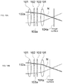
- FIGS. 15A and 15B schematically illustrates a distance to a subject and the incident light N
- FIGS. 16A and 16B schematically illustrates an image captured by the imaging element 104 (hereinafter referred to as a captured image).
- Focus is determined according to a distance to a subject and a focal length of the lens 101 .
- the position of an image is determined according to the distance to a subject when the focal length is constant.
- FIG. 15A When the image-capturing apparatus 100 is not focused on a subject H, as illustrated in FIG. 15A , light reaches different positions in the imaging element 104 depending on the position, in the lens 101 , through which the light passes.
- a subject image Z 1 captured with visible light and a subject image Z 2 captured with infrared light are shifted from each other in a captured image.
- the shift amount calculator 122 can detect the subject image Z 1 and the subject image Z 2 using an arbitrary object recognition algorithm, and calculate an amount of a shift between the subject image Z 1 and the subject image Z 2 .
- the distance-to-subject calculator 123 can calculate a distance to a subject using the focal length of the lens 101 and the shift amount since the focal length is known in the image-capturing apparatus 100 .
- FIG. 17 is a schematic diagram for explaining values related to a calculation of a distance to a subject.
- ⁇ is an amount of a shift between the subject image Z 1 and the subject image Z 2
- A is a distance between stops on a principal point (a distance between the infrared-opening-portion center P 1 and the visible-light-opening-portion center P 2 in a direction orthogonal to the optical axis)
- B is a distance from the principal point to the image surface 104 a .
- f is a focal length of a lens.
- Form 1 indicated below holds when light passes through the opening portion 102 a (in the upper portion in the figure) of the infrared stop 102 , and forms an image in a lower portion of the image surface 104 a , where the direction of a shift is different from the direction of a stop position, as illustrated in FIG. 18A .
- (Formula 2) indicated below holds when light passes through the opening portion 102 a (in the upper portion in the figure) of the infrared stop 102 , and forms an image in an upper portion of the image surface 104 a , where the direction of a shift is the same as the direction of a stop position, as illustrated in FIG. 18B .
- the distance-to-subject calculator 123 can calculate a distance to a subject by calculating L and Tf or Tr by use of (Formula 1) and (Formula 2).
- the centers of the opening portions of the infrared stop 102 and the visible light stop 103 may be changed according to a movement speed of the image-capturing apparatus 100 and an amount of light entering the imaging element 104 .
- FIGS. 19 and 20 schematically illustrate changes in the centers of the openings.
- a distance D between the infrared-opening-portion center P 1 and the visible-light-opening-portion center P 2 can be made large by making the infrared stop 102 and the visible light stop 103 small, as illustrated in FIG. 19 . This makes the amount of a shift between the subject image Z 1 and the subject image Z 2 large, which results in improving the accuracy in a calculation of a distance to a subject.
- the distance D between the infrared-opening-portion center P 1 and the visible-light-opening-portion center P 2 is made small by opening the infrared stop 102 and the visible light stop 103 , as illustrated in FIG. 20 .
- FIG. 22 is a graph illustrating a relationship between an amount of incident light or a movement speed, and a magnitude of a measurable shift.
- the structure according to the present embodiment (indicated by a solid line in the figure) makes it possible to measure a shift even if there is a change in an amount of incident light or in a movement speed, since blown-out highlights or blocked-up shadows are less likely to occur due to a greater flexibility in stops.
- the range in which a shift can be measured is relatively narrow in the conventional structure (indicated by a broken line in the figure).
- FIG. 23 is a table in which states of the infrared stop 102 and the visible light stop 103 in order to perform an optimal exposure, are given. An appropriate exposure can be performed by separately adjusting the infrared stop 102 and the visible light stop 103 , since the reflectance of infrared light differs depending on a subject.
- FIG. 24 is a table in which states of the infrared stop 102 and the visible light stop 103 in order to optimally measure a distance to a subject, are given.
- the distance range suitable for measurement is changed, since a distance between the infrared-opening-portion center P 1 and the visible-light-opening-portion center P 2 in the direction orthogonal to the optical axis, can be changed according to the opening level of a stop.
- the image-capturing apparatus 100 can control the focus of the image-capturing apparatus 100 using the calculated distance to a subject.
- the signal-processing preprocessing section 106 and the signal processing section 107 develop the read image (St 103 ).
- the shift amount calculator 122 detects a subject image Z 1 and a subject image Z 2 in the captured image, and calculates an amount of a shift between the subject image Z 1 and the subject image Z 2 (St 104 ).
- the distance-to-subject calculator 123 calculates a distance to a subject using the shift amount (St 105 ), and provides the calculated distance to a subject to the lens-movement-amount calculator 125 .
- the lens-movement-amount calculator 125 calculates, using the distance to a subject and a focal length, a lens-movement amount that is used to cause the image-capturing apparatus 100 to be focused on a subject (St 106 ), and provides the calculated lens-movement amount to the lens controller 112 .
- the image-capturing apparatus 100 can also generate a distance image using a calculated distance to a subject.
- the distance image is an image indicating a distance to a subject using, for example, brightness, color, or shading.
- FIG. 26 is a flowchart of an operation of generating a distance image that is performed by the image-capturing apparatus 100 .
- the imaging element 104 captures an image (St 111 )
- the captured image generator 121 generates a captured image.
- the imaging element I/F 105 reads an image signal from the imaging element 104 (St 112 ), and provides the image signal to the signal-processing preprocessing section 106 .
- the signal-processing preprocessing section 106 and the signal processing section 107 develop the read image (St 113 ).
- the shift amount calculator 122 detects a subject image Z 1 and a subject image Z 2 in the captured image, and calculates an amount of a shift between the subject image Z 1 and the subject image Z 2 (St 114 ).
- the distance-to-subject calculator 123 calculates a distance to a subject using the shift amount (St 115 ), and provides the calculated distance to a subject to the distance image generator 126 .
- the distance image generator 126 can generate a distance image by determining brightness or color for each specified pixel range according to the distance to a subject. After that, when an image is captured, the image-capturing apparatus 100 repeatedly performs the steps described above. The image-capturing apparatus 100 can generate a distance image, as described above.
- FIG. 27 is a flowchart of an operation of defocusing processing performed by the image-capturing apparatus 100 .
- the imaging element 104 captures an image (St 121 )
- the captured image generator 121 generates a captured image.
- the imaging element I/F 105 reads an image signal from the imaging element 104 (St 122 ), and provides the image signal to the signal-processing preprocessing section 106 .
- the signal-processing preprocessing section 106 and the signal processing section 107 develop the read image (St 123 ).
- the shift amount calculator 122 detects a subject image Z 1 and a subject image Z 2 in the captured image, and calculates an amount of a shift between the subject image Z 1 and the subject image Z 2 (St 124 ).
- the defocusing processing section 124 calculates a defocusing amount using the shift amount (St 125 ), and performs defocusing processing on the read captured image (St 126 ).
- the defocusing processing section 124 can perform the defocusing processing by performing convolution of the inverse of a distribution function of known blur.
- FIGS. 28A, 28B, and 28C schematically illustrates images that can be acquired by the image-capturing apparatus 100 .
- the image-capturing apparatus 100 makes it possible to capture a visible light image in FIG. 28A , an infrared image in FIG. 28B , and a distance image in FIG. 28C by performing a single piece of image-capturing (performing a single exposure).
- FIGS. 29A and 29B schematically illustrates a vehicle V equipped with the image-capturing apparatus 100 , and a subject H.
- the use of the image-capturing apparatus 100 makes it possible to acquire a visible light image, an infrared image, and a distance image, and to makes it possible to acquire, in a short time, information that is necessary for a movable object such as the vehicle V to perform a quick determination regarding its surroundings when, for example, automatic driving or automatic braking is applied.
- a distance between the vehicle V and the subject H can be acquired, as illustrated in FIG. 29A , or, for example, a gesture of a traffic control can be recognized, as illustrated in FIG. 29B .
- the image-capturing apparatus is highly adaptable to the external environment, and thus is suitable for such usage, since the infrared stop 102 and the visible light stop 103 can be separately adjusted, as described above.
- the image-capturing apparatus 100 can be installed in various movable objects.
- FIGS. 30A, 30B, 30C, 30D, and 30E illustrate examples of movable objects equipped with the image-capturing apparatus 100 .
- the image-capturing apparatus 100 may be installed in a vehicle such as an auto, a truck, or a train, as illustrated in FIG. 30A , or the image-capturing apparatus 100 may be installed in a flight vehicle such as a drone, an airplane, or an airship, as illustrated in FIG. 30B . Further, the image-capturing apparatus 100 may be installed in a remotely controlled apparatus such as a crane, as illustrated in FIG. 30C , or the image-capturing apparatus 100 may be installed in a light vehicle such as a bicycle, as illustrated in FIG. 30D . Furthermore, the image-capturing apparatus 100 may be installed in an independently movable object such as a robot, as illustrated in FIG. 30E . Moreover, the image-capturing apparatus 100 can be installed in various movable objects that can move with respect to a subject.
- the image-capturing apparatus 100 according to the present embodiment is also suitable for such an application, since the image-capturing apparatus 100 according to the present embodiment can acquire a distance to a subject and a visible light image at the same time, and thus can flexibly cope with an amount of external light.
- the infrared stop 102 includes the opening portion 102 a and the blocking portion 102 b , and is capable of adjusting a size of the opening portion 102 a , the opening portion 102 a being a portion through which infrared light and visible light included in the incident light N are transmitted, the blocking portion 102 b being a portion that blocks infrared light and through which visible light is transmitted.
- a configuration can be provided as indicated below.
- FIGS. 31, 32, 33A, 33B, 34A, and 34B schematically illustrate various configurations of the infrared stop 102 .
- a range S represents a range in which the incident light N passes.
- the infrared stop 102 may include a plurality of opening portions 102 a having different sizes. The size of the opening portion 102 a within the range S can be changed by the infrared stop 102 being rotated.
- the infrared stop 102 may also include a first member 102 c and a second member 102 d , in which the second member 102 d moves with respect to the first member 102 c .
- FIG. 33A illustrates a state in which a stop is opened
- FIG. 33B illustrates a state in which the stop is made small.
- the infrared stop 102 may also include a plurality of members 102 e , in which the size of the opening portion 102 a is changed by each member 102 e moving.
- FIG. 34A illustrates a state in which a stop is opened
- FIG. 34B illustrates a state in which the stop is made smaller.
- the position of the center of the infrared stop 102 can be shifted by moving the stop itself in a state between the state in which the stop is opened ( FIG. 34A ) and the state in which the stop is made smaller (of FIG. 34B ).
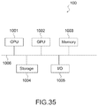
- FIG. 35 schematically illustrates a hardware configuration of the image-capturing apparatus 100 .
- the image-capturing apparatus 100 includes, as the hardware configuration, a CPU 1001 , a GPU 1002 , a memory 1003 , a storage 1004 , and an input/output section (I/O) 1005 . They are connected to one another through a bus 1006 . Further, the imaging element 104 or the like described above may also be connected to the bus 1006 .
- the CPU (central processing unit) 1001 controls other components in accordance with a program stored in the memory 1003 , and performs data processing in accordance with the program and stores a result of the processing in the memory 1003 .
- the CPU 1001 may be a microprocessor.
- the GPU (graphic processing unit) 1002 performs image processing by being controlled by the CPU 1001 .
- the GPU 1002 may be a microprocessor.
- the memory 1003 stores therein the program executed by the CPU 1001 , and data.
- the memory 1003 may be a random access memory (RAM).
- the input/output section 1005 receives an input to the image-capturing apparatus 100 , and provides an output from the image-capturing apparatus 100 to the outside.
- the input/output section 1005 includes an input device such as a keyboard or a mouse, an output device such as a display, and a connection interface such as a network.
- the hardware configuration of the image-capturing apparatus 100 is not limited to what has been described above, and it is sufficient if it can provide a functional configuration of the image-capturing apparatus 100 . Further, a portion of or all of the hardware configuration may exist on a network.
- the image-capturing apparatus 100 performs image-capturing with infrared light and visible light that are obtained by performing wavelength separation, but the embodiment is not limited to this example.
- the image-capturing apparatus 100 may perform image-capturing with first light of a first wavelength and with second light of a second a wavelength that are obtained by performing wavelength separation. It is sufficient if the first wavelength and the second wavelength are different from each other, and each of the wavelengths may be a wavelength of one of infrared light, ultraviolet light, or and visible light.
- the first opening portion and the second opening portion are shifted from each other in a direction orthogonal to a direction of an optical axis of the incident light.
- the image-capturing apparatus further including a distance-to-subject calculator that calculates a distance to a subject using a captured image that is captured by the imaging element, the captured image including a first image that is an image of the first light, and a second image that is an image of the second light.
- a distance-to-subject calculator that calculates a distance to a subject using a captured image that is captured by the imaging element, the captured image including a first image that is an image of the first light, and a second image that is an image of the second light.
- the distance-to-subject calculator calculates the distance to a subject using an amount of a shift between the first image and the second image in the captured image.
- the second wavelength is a wavelength of visible light
- the center of the first opening portion is shifted from the center of the optical axis of the incident light
- the center of the second opening portion coincides with the center of the optical axis of the incident light.
- the imaging element performs wavelength separation for the first wavelength and the second wavelength in a direction orthogonal to an optical axis of the incident light.
- the imaging element performs wavelength separation for the first wavelength and the second wavelength in a direction parallel to an optical axis of the incident light.
- the image-capturing apparatus according to (5), further including a distance image generator that generates a distance image from the distance to a subject.
- the image-capturing apparatus according to (3), further including a defocusing processing section that performs defocusing processing using an amount of a shift between a first image and a second image in a captured image that is captured by the imaging element, the captured image including the first image and the second image, the first image being an image of the first light, the second image being an image of the second light.
- a defocusing processing section that performs defocusing processing using an amount of a shift between a first image and a second image in a captured image that is captured by the imaging element, the captured image including the first image and the second image, the first image being an image of the first light, the second image being an image of the second light.
- the stop controller controls a size of the first opening portion and a size of the second opening portion according to an amount of the first light entering the imaging element and an amount of the second light entering the imaging element.
- the stop controller controls a distance between a center of the first opening portion and a center of the second opening portion in a direction orthogonal to an optical axis of the incident light according to a movement speed of the image-capturing apparatus.
- An image-capturing method using an image-capturing apparatus including
- an imaging element that performs wavelength separation on incident light to obtain first light of a first wavelength and second light of a second wavelength, and photoelectrically converts the first light and the second light, the first light and the second light being included in the incident light;
- a first stop that is provided in a path of the incident light, and includes a first opening portion and a first blocking portion, the first opening portion being a portion through which the first light and the second light are transmitted, the first blocking portion being a portion that blocks the first light and through which the second light is transmitted;
- a stop controller separately changes a size of the first opening portion and a size of the second opening portion.
- a program for controlling an image-capturing apparatus, the image-capturing apparatus including
- an imaging element that performs wavelength separation on incident light to obtain first light of a first wavelength and second light of a second wavelength, and photoelectrically converts the first light and the second light, the first light and the second light being included in the incident light;
- a first stop that is provided in a path of the incident light, and includes a first opening portion and a first blocking portion, the first opening portion being a portion through which the first light and the second light are transmitted, the first blocking portion being a portion that blocks the first light and through which the second light is transmitted;
- a second stop that is provided in the path of the incident light, and includes a second opening portion and a second blocking portion, the second opening portion being a portion through which the first light and the second light are transmitted, the second blocking portion being a portion that blocks the second light and through which the first light is transmitted, in which
- the program controls the image-capturing apparatus as a stop controller that separately changes a size of the first opening portion and a size of the second opening portion.
Landscapes
- Physics & Mathematics (AREA)
- General Physics & Mathematics (AREA)
- Engineering & Computer Science (AREA)
- Multimedia (AREA)
- Signal Processing (AREA)
- Optics & Photonics (AREA)
- Computer Vision & Pattern Recognition (AREA)
- Studio Devices (AREA)
- Exposure Control For Cameras (AREA)
- Measurement Of Optical Distance (AREA)
- Focusing (AREA)
- Camera Bodies And Camera Details Or Accessories (AREA)
- Automatic Focus Adjustment (AREA)
- Transforming Light Signals Into Electric Signals (AREA)
- Blocking Light For Cameras (AREA)
- Diaphragms For Cameras (AREA)
Abstract
Description
(6) The image-capturing apparatus according to (5), in which
(13) The image-capturing apparatus according to any one of (1) to (12), in which
- 100 image-capturing apparatus
- 101 lens
- 102 infrared stop
- 103 visible light stop
- 104 imaging element
- 105 imaging element I/F
- 106 signal-processing preprocessing section
- 107 signal processing section
- 108 display processing section
- 109 display section
- 110 output processing section
- 111 output section
- 112 lens controller
- 113 computing section
- 114 volatile storage section
- 115 nonvolatile storage section
- 116 nonvolatile storage I/F
- 117 input section
- 118 input processing section
- 119 stop controller
- 121 captured image generator
- 122 shift amount calculator
- 123 distance-to-subject calculator
- 124 defocusing processing section
- 125 lens-movement-amount calculator
- 126 distance image generator
Claims (15)
Applications Claiming Priority (4)
| Application Number | Priority Date | Filing Date | Title |
|---|---|---|---|
| JP2017-158532 | 2017-08-21 | ||
| JPJP2017-158532 | 2017-08-21 | ||
| JP2017158532 | 2017-08-21 | ||
| PCT/JP2018/027057 WO2019039144A1 (en) | 2017-08-21 | 2018-07-19 | Image capture device, image capture method, and program |
Publications (2)
| Publication Number | Publication Date |
|---|---|
| US20200374441A1 US20200374441A1 (en) | 2020-11-26 |
| US11223781B2 true US11223781B2 (en) | 2022-01-11 |
Family
ID=65438623
Family Applications (1)
| Application Number | Title | Priority Date | Filing Date |
|---|---|---|---|
| US16/638,505 Expired - Fee Related US11223781B2 (en) | 2017-08-21 | 2018-07-19 | Image-capturing apparatus and image-capturing method |
Country Status (4)
| Country | Link |
|---|---|
| US (1) | US11223781B2 (en) |
| JP (1) | JPWO2019039144A1 (en) |
| DE (1) | DE112018004805T5 (en) |
| WO (1) | WO2019039144A1 (en) |
Families Citing this family (1)
| Publication number | Priority date | Publication date | Assignee | Title |
|---|---|---|---|---|
| JP2025004665A (en) * | 2023-06-26 | 2025-01-15 | キヤノン株式会社 | Information processing device, imaging device, control method and program |
Citations (11)
| Publication number | Priority date | Publication date | Assignee | Title |
|---|---|---|---|---|
| US20020186976A1 (en) * | 2001-06-08 | 2002-12-12 | Asahi Kogaku Kogyo Kabushiki Kaisha | Image-capturing device and diaphragm |
| JP2006238093A (en) | 2005-02-25 | 2006-09-07 | Sony Corp | Imaging device |
| JP2012022308A (en) | 2010-06-14 | 2012-02-02 | Nikon Corp | Imaging device |
| CN102868864A (en) | 2011-07-06 | 2013-01-09 | 索尼公司 | Solid-state imaging device and electronic apparatus |
| US20130334402A1 (en) * | 2012-06-14 | 2013-12-19 | Sony Corporation | Solid-state imagingelement, calibration method of solid-state imagingelement, shutter device, and electronic apparatus |
| US20140133004A1 (en) * | 2011-06-15 | 2014-05-15 | Optoquest Co., Ltd. | Wavelength selection polarization controller |
| WO2014122714A1 (en) | 2013-02-07 | 2014-08-14 | パナソニック株式会社 | Image-capturing device and drive method therefor |
| JP2015195489A (en) | 2014-03-31 | 2015-11-05 | パナソニックIpマネジメント株式会社 | Collision preventing system, collision preventing method and computer program |
| US20150365609A1 (en) * | 2014-06-16 | 2015-12-17 | Canon Kabushiki Kaisha | Image capturing apparatus, method for controlling the same, and storage medium |
| US20170094198A1 (en) * | 2015-09-30 | 2017-03-30 | Samsung Electronics Co., Ltd. | Electronic device |
| US20200025882A1 (en) * | 2016-09-21 | 2020-01-23 | Nec Corporation | Distance measurement system, distance measurement method, and program recording medium |
-
2018
- 2018-07-19 US US16/638,505 patent/US11223781B2/en not_active Expired - Fee Related
- 2018-07-19 DE DE112018004805.5T patent/DE112018004805T5/en not_active Withdrawn
- 2018-07-19 WO PCT/JP2018/027057 patent/WO2019039144A1/en not_active Ceased
- 2018-07-19 JP JP2019537990A patent/JPWO2019039144A1/en not_active Abandoned
Patent Citations (16)
| Publication number | Priority date | Publication date | Assignee | Title |
|---|---|---|---|---|
| JP2002369049A (en) | 2001-06-08 | 2002-12-20 | Pentax Corp | Image detection device and aperture device |
| US20020186976A1 (en) * | 2001-06-08 | 2002-12-12 | Asahi Kogaku Kogyo Kabushiki Kaisha | Image-capturing device and diaphragm |
| JP2006238093A (en) | 2005-02-25 | 2006-09-07 | Sony Corp | Imaging device |
| US20070051876A1 (en) | 2005-02-25 | 2007-03-08 | Hirofumi Sumi | Imager |
| JP2012022308A (en) | 2010-06-14 | 2012-02-02 | Nikon Corp | Imaging device |
| US20140133004A1 (en) * | 2011-06-15 | 2014-05-15 | Optoquest Co., Ltd. | Wavelength selection polarization controller |
| CN102868864A (en) | 2011-07-06 | 2013-01-09 | 索尼公司 | Solid-state imaging device and electronic apparatus |
| US20130009263A1 (en) | 2011-07-06 | 2013-01-10 | Sony Corporation | Solid-state imaging device and electronic apparatus |
| JP2013016729A (en) | 2011-07-06 | 2013-01-24 | Sony Corp | Solid state image pickup device and electronic apparatus |
| US20130334402A1 (en) * | 2012-06-14 | 2013-12-19 | Sony Corporation | Solid-state imagingelement, calibration method of solid-state imagingelement, shutter device, and electronic apparatus |
| WO2014122714A1 (en) | 2013-02-07 | 2014-08-14 | パナソニック株式会社 | Image-capturing device and drive method therefor |
| US20150341573A1 (en) | 2013-02-07 | 2015-11-26 | Panasonic Intellectual Property Management Co., Ltd. | Image-capturing device and drive method therefor |
| JP2015195489A (en) | 2014-03-31 | 2015-11-05 | パナソニックIpマネジメント株式会社 | Collision preventing system, collision preventing method and computer program |
| US20150365609A1 (en) * | 2014-06-16 | 2015-12-17 | Canon Kabushiki Kaisha | Image capturing apparatus, method for controlling the same, and storage medium |
| US20170094198A1 (en) * | 2015-09-30 | 2017-03-30 | Samsung Electronics Co., Ltd. | Electronic device |
| US20200025882A1 (en) * | 2016-09-21 | 2020-01-23 | Nec Corporation | Distance measurement system, distance measurement method, and program recording medium |
Non-Patent Citations (1)
| Title |
|---|
| International Search Report and Written Opinion of PCT Application No. PCT/JP2018/027057, dated Oct. 2, 2018, 10 pages of ISRWO. |
Also Published As
| Publication number | Publication date |
|---|---|
| US20200374441A1 (en) | 2020-11-26 |
| JPWO2019039144A1 (en) | 2020-10-15 |
| DE112018004805T5 (en) | 2020-06-10 |
| WO2019039144A1 (en) | 2019-02-28 |
Similar Documents
| Publication | Publication Date | Title |
|---|---|---|
| US10326927B2 (en) | Distance information producing apparatus, image capturing apparatus, distance information producing method and storage medium storing distance information producing program | |
| JP5387856B2 (en) | Image processing apparatus, image processing method, image processing program, and imaging apparatus | |
| JP5315574B2 (en) | Imaging device | |
| US11333927B2 (en) | Image processing device, image capturing device, and image processing method | |
| US10321044B2 (en) | Image pickup apparatus and image pickup system with point image intensity distribution calculation | |
| US9759549B2 (en) | Distance detecting device | |
| US11388383B2 (en) | Image processing apparatus, image pickup apparatus, image processing method, and non-transitory computer-readable storage medium | |
| US20170257583A1 (en) | Image processing device and control method thereof | |
| US10602050B2 (en) | Image pickup apparatus and control method therefor | |
| US20180048805A1 (en) | Control apparatus for performing focus detection, image capturing apparatus, control method, and non-transitory computer-readable storage medium | |
| US11223781B2 (en) | Image-capturing apparatus and image-capturing method | |
| US12189208B2 (en) | Lens control device, imaging apparatus, operation method of lens control device, and program | |
| Kane | Signal detection theory and automotive imaging | |
| US20250124585A1 (en) | Imaging apparatus, subject depth estimation method, and program | |
| US10200622B2 (en) | Image processing method, image processing apparatus, and imaging apparatus | |
| US11037316B2 (en) | Parallax calculation apparatus, parallax calculation method, and control program of parallax calculation apparatus | |
| US10339665B2 (en) | Positional shift amount calculation apparatus and imaging apparatus | |
| EP4306904A1 (en) | Calibration method for distance measurement device, distance measurement device, and storage medium | |
| US9402069B2 (en) | Depth measurement apparatus, imaging apparatus, and method of controlling depth measurement apparatus | |
| JP5673764B2 (en) | Image processing apparatus, image processing method, image processing program, and recording medium | |
| JP5904716B2 (en) | IMAGING DEVICE, IMAGING DEVICE CONTROL METHOD, AND PROGRAM | |
| KR102675416B1 (en) | Optical spectrum measuring apparatus, optical spectrum measuring method, and optical spectrum measuring system | |
| JP2014056182A (en) | Imaging device and imaging apparatus | |
| EP4708195A1 (en) | Image processing apparatus, image processing method, and storage medium | |
| CN113596431A (en) | Image processing apparatus, image capturing apparatus, image processing method, and storage medium |
Legal Events
| Date | Code | Title | Description |
|---|---|---|---|
| FEPP | Fee payment procedure |
Free format text: ENTITY STATUS SET TO UNDISCOUNTED (ORIGINAL EVENT CODE: BIG.); ENTITY STATUS OF PATENT OWNER: LARGE ENTITY |
|
| AS | Assignment |
Owner name: SONY CORPORATION, JAPAN Free format text: ASSIGNMENT OF ASSIGNORS INTEREST;ASSIGNOR:OZAKI, KOJI;REEL/FRAME:052618/0350 Effective date: 20200308 |
|
| STPP | Information on status: patent application and granting procedure in general |
Free format text: DOCKETED NEW CASE - READY FOR EXAMINATION |
|
| STPP | Information on status: patent application and granting procedure in general |
Free format text: NON FINAL ACTION MAILED |
|
| STPP | Information on status: patent application and granting procedure in general |
Free format text: RESPONSE TO NON-FINAL OFFICE ACTION ENTERED AND FORWARDED TO EXAMINER |
|
| STPP | Information on status: patent application and granting procedure in general |
Free format text: NOTICE OF ALLOWANCE MAILED -- APPLICATION RECEIVED IN OFFICE OF PUBLICATIONS |
|
| STPP | Information on status: patent application and granting procedure in general |
Free format text: PUBLICATIONS -- ISSUE FEE PAYMENT RECEIVED |
|
| STPP | Information on status: patent application and granting procedure in general |
Free format text: PUBLICATIONS -- ISSUE FEE PAYMENT VERIFIED |
|
| STCF | Information on status: patent grant |
Free format text: PATENTED CASE |
|
| FEPP | Fee payment procedure |
Free format text: MAINTENANCE FEE REMINDER MAILED (ORIGINAL EVENT CODE: REM.); ENTITY STATUS OF PATENT OWNER: LARGE ENTITY |
|
| LAPS | Lapse for failure to pay maintenance fees |
Free format text: PATENT EXPIRED FOR FAILURE TO PAY MAINTENANCE FEES (ORIGINAL EVENT CODE: EXP.); ENTITY STATUS OF PATENT OWNER: LARGE ENTITY |
|
| STCH | Information on status: patent discontinuation |
Free format text: PATENT EXPIRED DUE TO NONPAYMENT OF MAINTENANCE FEES UNDER 37 CFR 1.362 |
|
| FP | Lapsed due to failure to pay maintenance fee |
Effective date: 20260111 |