US11223667B2 - Low latency wireless communication system for teleoperated vehicle environments - Google Patents
Low latency wireless communication system for teleoperated vehicle environments Download PDFInfo
- Publication number
- US11223667B2 US11223667B2 US16/862,513 US202016862513A US11223667B2 US 11223667 B2 US11223667 B2 US 11223667B2 US 202016862513 A US202016862513 A US 202016862513A US 11223667 B2 US11223667 B2 US 11223667B2
- Authority
- US
- United States
- Prior art keywords
- video segment
- encoding
- video
- wireless network
- encoded video
- Prior art date
- Legal status (The legal status is an assumption and is not a legal conclusion. Google has not performed a legal analysis and makes no representation as to the accuracy of the status listed.)
- Active
Links
- 238000004891 communication Methods 0.000 title claims abstract description 90
- 230000005540 biological transmission Effects 0.000 claims abstract description 38
- 238000000034 method Methods 0.000 claims description 62
- 238000003860 storage Methods 0.000 claims description 15
- 238000005457 optimization Methods 0.000 claims description 14
- 238000004422 calculation algorithm Methods 0.000 claims description 13
- 230000001419 dependent effect Effects 0.000 abstract description 3
- 238000004088 simulation Methods 0.000 description 34
- 230000008569 process Effects 0.000 description 27
- 239000000872 buffer Substances 0.000 description 26
- 230000006870 function Effects 0.000 description 25
- 239000013598 vector Substances 0.000 description 18
- 230000000295 complement effect Effects 0.000 description 16
- 230000009471 action Effects 0.000 description 15
- 230000001413 cellular effect Effects 0.000 description 14
- 238000012549 training Methods 0.000 description 11
- 238000013528 artificial neural network Methods 0.000 description 10
- 238000013459 approach Methods 0.000 description 9
- 238000010586 diagram Methods 0.000 description 9
- 238000005516 engineering process Methods 0.000 description 8
- 230000004807 localization Effects 0.000 description 8
- 238000012545 processing Methods 0.000 description 8
- 239000003795 chemical substances by application Substances 0.000 description 7
- 230000015654 memory Effects 0.000 description 7
- 238000012544 monitoring process Methods 0.000 description 7
- 238000013473 artificial intelligence Methods 0.000 description 6
- 230000006855 networking Effects 0.000 description 6
- 238000013442 quality metrics Methods 0.000 description 5
- 230000007246 mechanism Effects 0.000 description 4
- 230000003287 optical effect Effects 0.000 description 4
- 239000000523 sample Substances 0.000 description 4
- 230000001133 acceleration Effects 0.000 description 3
- 239000000969 carrier Substances 0.000 description 3
- 238000004590 computer program Methods 0.000 description 3
- 238000001914 filtration Methods 0.000 description 3
- 230000003278 mimic effect Effects 0.000 description 3
- 230000000644 propagated effect Effects 0.000 description 3
- 230000002441 reversible effect Effects 0.000 description 3
- 230000001052 transient effect Effects 0.000 description 3
- 230000000007 visual effect Effects 0.000 description 3
- 230000006978 adaptation Effects 0.000 description 2
- 239000000654 additive Substances 0.000 description 2
- 230000000996 additive effect Effects 0.000 description 2
- 230000008901 benefit Effects 0.000 description 2
- 238000010276 construction Methods 0.000 description 2
- 238000001514 detection method Methods 0.000 description 2
- 238000011161 development Methods 0.000 description 2
- 238000009826 distribution Methods 0.000 description 2
- 230000007613 environmental effect Effects 0.000 description 2
- 230000001976 improved effect Effects 0.000 description 2
- 238000011065 in-situ storage Methods 0.000 description 2
- 238000010801 machine learning Methods 0.000 description 2
- 238000013507 mapping Methods 0.000 description 2
- 230000004048 modification Effects 0.000 description 2
- 238000012986 modification Methods 0.000 description 2
- 230000002085 persistent effect Effects 0.000 description 2
- 230000009467 reduction Effects 0.000 description 2
- 230000002787 reinforcement Effects 0.000 description 2
- 238000010845 search algorithm Methods 0.000 description 2
- 230000009897 systematic effect Effects 0.000 description 2
- 238000012795 verification Methods 0.000 description 2
- 241000023320 Luma <angiosperm> Species 0.000 description 1
- 238000009825 accumulation Methods 0.000 description 1
- 230000003213 activating effect Effects 0.000 description 1
- 230000004913 activation Effects 0.000 description 1
- 230000002776 aggregation Effects 0.000 description 1
- 238000004220 aggregation Methods 0.000 description 1
- 238000004458 analytical method Methods 0.000 description 1
- 238000010420 art technique Methods 0.000 description 1
- 230000004888 barrier function Effects 0.000 description 1
- 230000002457 bidirectional effect Effects 0.000 description 1
- 238000004364 calculation method Methods 0.000 description 1
- 230000015556 catabolic process Effects 0.000 description 1
- 230000008859 change Effects 0.000 description 1
- 230000008867 communication pathway Effects 0.000 description 1
- 239000002131 composite material Substances 0.000 description 1
- 230000001276 controlling effect Effects 0.000 description 1
- 238000013527 convolutional neural network Methods 0.000 description 1
- 230000006735 deficit Effects 0.000 description 1
- 238000006731 degradation reaction Methods 0.000 description 1
- 230000001934 delay Effects 0.000 description 1
- 238000013461 design Methods 0.000 description 1
- 230000002542 deteriorative effect Effects 0.000 description 1
- 230000003467 diminishing effect Effects 0.000 description 1
- 238000005315 distribution function Methods 0.000 description 1
- 230000000193 eyeblink Effects 0.000 description 1
- 231100001261 hazardous Toxicity 0.000 description 1
- 230000036541 health Effects 0.000 description 1
- 230000006872 improvement Effects 0.000 description 1
- 230000000977 initiatory effect Effects 0.000 description 1
- 238000011835 investigation Methods 0.000 description 1
- 238000007726 management method Methods 0.000 description 1
- 238000004519 manufacturing process Methods 0.000 description 1
- 239000011159 matrix material Substances 0.000 description 1
- 238000005259 measurement Methods 0.000 description 1
- OSWPMRLSEDHDFF-UHFFFAOYSA-N methyl salicylate Chemical compound COC(=O)C1=CC=CC=C1O OSWPMRLSEDHDFF-UHFFFAOYSA-N 0.000 description 1
- 238000002156 mixing Methods 0.000 description 1
- 239000000203 mixture Substances 0.000 description 1
- 230000000737 periodic effect Effects 0.000 description 1
- 230000001902 propagating effect Effects 0.000 description 1
- 238000013138 pruning Methods 0.000 description 1
- 230000004478 pupil constriction Effects 0.000 description 1
- 230000010344 pupil dilation Effects 0.000 description 1
- 238000001303 quality assessment method Methods 0.000 description 1
- 238000013139 quantization Methods 0.000 description 1
- 230000001105 regulatory effect Effects 0.000 description 1
- 238000009877 rendering Methods 0.000 description 1
- 238000005316 response function Methods 0.000 description 1
- 230000008054 signal transmission Effects 0.000 description 1
- 230000005477 standard model Effects 0.000 description 1
- 239000000126 substance Substances 0.000 description 1
- 230000008093 supporting effect Effects 0.000 description 1
- 238000013526 transfer learning Methods 0.000 description 1
- 230000009466 transformation Effects 0.000 description 1
- 238000011144 upstream manufacturing Methods 0.000 description 1
- 230000001755 vocal effect Effects 0.000 description 1
Images


Classifications
-
- H04L65/607—
-
- H—ELECTRICITY
- H04—ELECTRIC COMMUNICATION TECHNIQUE
- H04L—TRANSMISSION OF DIGITAL INFORMATION, e.g. TELEGRAPHIC COMMUNICATION
- H04L65/00—Network arrangements, protocols or services for supporting real-time applications in data packet communication
- H04L65/80—Responding to QoS
-
- H—ELECTRICITY
- H04—ELECTRIC COMMUNICATION TECHNIQUE
- H04L—TRANSMISSION OF DIGITAL INFORMATION, e.g. TELEGRAPHIC COMMUNICATION
- H04L41/00—Arrangements for maintenance, administration or management of data switching networks, e.g. of packet switching networks
- H04L41/08—Configuration management of networks or network elements
- H04L41/0894—Policy-based network configuration management
-
- H—ELECTRICITY
- H04—ELECTRIC COMMUNICATION TECHNIQUE
- H04L—TRANSMISSION OF DIGITAL INFORMATION, e.g. TELEGRAPHIC COMMUNICATION
- H04L41/00—Arrangements for maintenance, administration or management of data switching networks, e.g. of packet switching networks
- H04L41/14—Network analysis or design
- H04L41/145—Network analysis or design involving simulating, designing, planning or modelling of a network
-
- H—ELECTRICITY
- H04—ELECTRIC COMMUNICATION TECHNIQUE
- H04L—TRANSMISSION OF DIGITAL INFORMATION, e.g. TELEGRAPHIC COMMUNICATION
- H04L41/00—Arrangements for maintenance, administration or management of data switching networks, e.g. of packet switching networks
- H04L41/16—Arrangements for maintenance, administration or management of data switching networks, e.g. of packet switching networks using machine learning or artificial intelligence
-
- H—ELECTRICITY
- H04—ELECTRIC COMMUNICATION TECHNIQUE
- H04L—TRANSMISSION OF DIGITAL INFORMATION, e.g. TELEGRAPHIC COMMUNICATION
- H04L43/00—Arrangements for monitoring or testing data switching networks
- H04L43/08—Monitoring or testing based on specific metrics, e.g. QoS, energy consumption or environmental parameters
- H04L43/0852—Delays
- H04L43/0864—Round trip delays
-
- H—ELECTRICITY
- H04—ELECTRIC COMMUNICATION TECHNIQUE
- H04L—TRANSMISSION OF DIGITAL INFORMATION, e.g. TELEGRAPHIC COMMUNICATION
- H04L43/00—Arrangements for monitoring or testing data switching networks
- H04L43/08—Monitoring or testing based on specific metrics, e.g. QoS, energy consumption or environmental parameters
- H04L43/0852—Delays
- H04L43/087—Jitter
-
- H—ELECTRICITY
- H04—ELECTRIC COMMUNICATION TECHNIQUE
- H04L—TRANSMISSION OF DIGITAL INFORMATION, e.g. TELEGRAPHIC COMMUNICATION
- H04L43/00—Arrangements for monitoring or testing data switching networks
- H04L43/16—Threshold monitoring
-
- H—ELECTRICITY
- H04—ELECTRIC COMMUNICATION TECHNIQUE
- H04L—TRANSMISSION OF DIGITAL INFORMATION, e.g. TELEGRAPHIC COMMUNICATION
- H04L65/00—Network arrangements, protocols or services for supporting real-time applications in data packet communication
- H04L65/1066—Session management
- H04L65/1083—In-session procedures
- H04L65/1095—Inter-network session transfer or sharing
-
- H—ELECTRICITY
- H04—ELECTRIC COMMUNICATION TECHNIQUE
- H04L—TRANSMISSION OF DIGITAL INFORMATION, e.g. TELEGRAPHIC COMMUNICATION
- H04L65/00—Network arrangements, protocols or services for supporting real-time applications in data packet communication
- H04L65/60—Network streaming of media packets
- H04L65/61—Network streaming of media packets for supporting one-way streaming services, e.g. Internet radio
-
- H—ELECTRICITY
- H04—ELECTRIC COMMUNICATION TECHNIQUE
- H04L—TRANSMISSION OF DIGITAL INFORMATION, e.g. TELEGRAPHIC COMMUNICATION
- H04L65/00—Network arrangements, protocols or services for supporting real-time applications in data packet communication
- H04L65/60—Network streaming of media packets
- H04L65/70—Media network packetisation
-
- H—ELECTRICITY
- H04—ELECTRIC COMMUNICATION TECHNIQUE
- H04L—TRANSMISSION OF DIGITAL INFORMATION, e.g. TELEGRAPHIC COMMUNICATION
- H04L65/00—Network arrangements, protocols or services for supporting real-time applications in data packet communication
- H04L65/60—Network streaming of media packets
- H04L65/75—Media network packet handling
- H04L65/752—Media network packet handling adapting media to network capabilities
-
- H—ELECTRICITY
- H04—ELECTRIC COMMUNICATION TECHNIQUE
- H04L—TRANSMISSION OF DIGITAL INFORMATION, e.g. TELEGRAPHIC COMMUNICATION
- H04L65/00—Network arrangements, protocols or services for supporting real-time applications in data packet communication
- H04L65/60—Network streaming of media packets
- H04L65/75—Media network packet handling
- H04L65/762—Media network packet handling at the source
-
- H—ELECTRICITY
- H04—ELECTRIC COMMUNICATION TECHNIQUE
- H04L—TRANSMISSION OF DIGITAL INFORMATION, e.g. TELEGRAPHIC COMMUNICATION
- H04L67/00—Network arrangements or protocols for supporting network services or applications
- H04L67/01—Protocols
- H04L67/02—Protocols based on web technology, e.g. hypertext transfer protocol [HTTP]
- H04L67/025—Protocols based on web technology, e.g. hypertext transfer protocol [HTTP] for remote control or remote monitoring of applications
-
- H—ELECTRICITY
- H04—ELECTRIC COMMUNICATION TECHNIQUE
- H04N—PICTORIAL COMMUNICATION, e.g. TELEVISION
- H04N19/00—Methods or arrangements for coding, decoding, compressing or decompressing digital video signals
- H04N19/10—Methods or arrangements for coding, decoding, compressing or decompressing digital video signals using adaptive coding
- H04N19/134—Methods or arrangements for coding, decoding, compressing or decompressing digital video signals using adaptive coding characterised by the element, parameter or criterion affecting or controlling the adaptive coding
- H04N19/164—Feedback from the receiver or from the transmission channel
-
- H—ELECTRICITY
- H04—ELECTRIC COMMUNICATION TECHNIQUE
- H04N—PICTORIAL COMMUNICATION, e.g. TELEVISION
- H04N19/00—Methods or arrangements for coding, decoding, compressing or decompressing digital video signals
- H04N19/10—Methods or arrangements for coding, decoding, compressing or decompressing digital video signals using adaptive coding
- H04N19/169—Methods or arrangements for coding, decoding, compressing or decompressing digital video signals using adaptive coding characterised by the coding unit, i.e. the structural portion or semantic portion of the video signal being the object or the subject of the adaptive coding
- H04N19/17—Methods or arrangements for coding, decoding, compressing or decompressing digital video signals using adaptive coding characterised by the coding unit, i.e. the structural portion or semantic portion of the video signal being the object or the subject of the adaptive coding the unit being an image region, e.g. an object
- H04N19/172—Methods or arrangements for coding, decoding, compressing or decompressing digital video signals using adaptive coding characterised by the coding unit, i.e. the structural portion or semantic portion of the video signal being the object or the subject of the adaptive coding the unit being an image region, e.g. an object the region being a picture, frame or field
-
- H—ELECTRICITY
- H04—ELECTRIC COMMUNICATION TECHNIQUE
- H04N—PICTORIAL COMMUNICATION, e.g. TELEVISION
- H04N19/00—Methods or arrangements for coding, decoding, compressing or decompressing digital video signals
- H04N19/46—Embedding additional information in the video signal during the compression process
-
- H—ELECTRICITY
- H04—ELECTRIC COMMUNICATION TECHNIQUE
- H04N—PICTORIAL COMMUNICATION, e.g. TELEVISION
- H04N19/00—Methods or arrangements for coding, decoding, compressing or decompressing digital video signals
- H04N19/60—Methods or arrangements for coding, decoding, compressing or decompressing digital video signals using transform coding
- H04N19/61—Methods or arrangements for coding, decoding, compressing or decompressing digital video signals using transform coding in combination with predictive coding
-
- H—ELECTRICITY
- H04—ELECTRIC COMMUNICATION TECHNIQUE
- H04N—PICTORIAL COMMUNICATION, e.g. TELEVISION
- H04N21/00—Selective content distribution, e.g. interactive television or video on demand [VOD]
- H04N21/20—Servers specifically adapted for the distribution of content, e.g. VOD servers; Operations thereof
- H04N21/25—Management operations performed by the server for facilitating the content distribution or administrating data related to end-users or client devices, e.g. end-user or client device authentication, learning user preferences for recommending movies
- H04N21/266—Channel or content management, e.g. generation and management of keys and entitlement messages in a conditional access system, merging a VOD unicast channel into a multicast channel
- H04N21/2665—Gathering content from different sources, e.g. Internet and satellite
-
- H—ELECTRICITY
- H04—ELECTRIC COMMUNICATION TECHNIQUE
- H04N—PICTORIAL COMMUNICATION, e.g. TELEVISION
- H04N21/00—Selective content distribution, e.g. interactive television or video on demand [VOD]
- H04N21/40—Client devices specifically adapted for the reception of or interaction with content, e.g. set-top-box [STB]; Operations thereof
- H04N21/41—Structure of client; Structure of client peripherals
- H04N21/414—Specialised client platforms, e.g. receiver in car or embedded in a mobile appliance
- H04N21/41422—Specialised client platforms, e.g. receiver in car or embedded in a mobile appliance located in transportation means, e.g. personal vehicle
-
- H—ELECTRICITY
- H04—ELECTRIC COMMUNICATION TECHNIQUE
- H04W—WIRELESS COMMUNICATION NETWORKS
- H04W4/00—Services specially adapted for wireless communication networks; Facilities therefor
- H04W4/30—Services specially adapted for particular environments, situations or purposes
- H04W4/40—Services specially adapted for particular environments, situations or purposes for vehicles, e.g. vehicle-to-pedestrians [V2P]
-
- H—ELECTRICITY
- H04—ELECTRIC COMMUNICATION TECHNIQUE
- H04N—PICTORIAL COMMUNICATION, e.g. TELEVISION
- H04N19/00—Methods or arrangements for coding, decoding, compressing or decompressing digital video signals
- H04N19/10—Methods or arrangements for coding, decoding, compressing or decompressing digital video signals using adaptive coding
- H04N19/102—Methods or arrangements for coding, decoding, compressing or decompressing digital video signals using adaptive coding characterised by the element, parameter or selection affected or controlled by the adaptive coding
- H04N19/103—Selection of coding mode or of prediction mode
-
- H—ELECTRICITY
- H04—ELECTRIC COMMUNICATION TECHNIQUE
- H04N—PICTORIAL COMMUNICATION, e.g. TELEVISION
- H04N19/00—Methods or arrangements for coding, decoding, compressing or decompressing digital video signals
- H04N19/10—Methods or arrangements for coding, decoding, compressing or decompressing digital video signals using adaptive coding
- H04N19/134—Methods or arrangements for coding, decoding, compressing or decompressing digital video signals using adaptive coding characterised by the element, parameter or criterion affecting or controlling the adaptive coding
- H04N19/154—Measured or subjectively estimated visual quality after decoding, e.g. measurement of distortion
-
- H—ELECTRICITY
- H04—ELECTRIC COMMUNICATION TECHNIQUE
- H04N—PICTORIAL COMMUNICATION, e.g. TELEVISION
- H04N19/00—Methods or arrangements for coding, decoding, compressing or decompressing digital video signals
- H04N19/10—Methods or arrangements for coding, decoding, compressing or decompressing digital video signals using adaptive coding
- H04N19/169—Methods or arrangements for coding, decoding, compressing or decompressing digital video signals using adaptive coding characterised by the coding unit, i.e. the structural portion or semantic portion of the video signal being the object or the subject of the adaptive coding
- H04N19/179—Methods or arrangements for coding, decoding, compressing or decompressing digital video signals using adaptive coding characterised by the coding unit, i.e. the structural portion or semantic portion of the video signal being the object or the subject of the adaptive coding the unit being a scene or a shot
Definitions
- the disclosed embodiments relate generally to the field of remote teleoperation and more specifically to a system and method for maintaining redundant low latency data transmission channels over multiple wireless links.
- a key factor for these applications is the development of techniques for reliable and low-latency data transmission over wireless networks, including public cellular carriers. Due to the specifics of modern network engineering, data transmission even at a slightly higher bit rate than can be supported by a network link at the time may generate buffer bloat and lead to network congestion, detrimentally affecting data latency. To solve this problem, congestion control algorithms and methods are being actively researched.
- congestion control algorithms for single-path transmissions alone cannot provide the safety level demanded by cloud robotics applications that require monitoring states of remote clients or their environment and supervising their actions in substantially real time. This issue is especially exacerbated in scenarios involving public networks and highly-mobile robotic units such as autonomous vehicles.
- a system, method, and non-transitory computer-readable storage medium facilitates wireless transmission of low latency video or other data for teleoperation or other remote support, monitoring, or control applications.
- a teleoperated vehicle generates a plurality of data including subsets of complementary data streams having redundant data.
- a network orchestrator generates assignments for transmitting the plurality of data streams over at least two different wireless network connections. The assignments are made so that each data stream within one of the subsets of complementary data streams is assigned to different ones of the wireless network connections.
- a plurality of communication units transmits the plurality of data streams over the at least two wireless network connections based on the assignments.
- generating the assignments by the network orchestrator comprises applying an optimization algorithm to optimize the assignments according to a predefined optimization criterion.
- the optimization criterion may comprise at least one of minimizing predicting latency, minimizing predicted network congestion, and maximizing predicted quality.
- the assignments may be based at least in part on a machine-learned model derived from simulations of a vehicle traversing areas of varying network conditions.
- a source wireless communicates low latency video to a remote support server during a remote support session.
- the source receives a first video feed from a first camera.
- a first encoder encodes the first video segment of the first video feed to generate a first encoded video segment
- a second encoder encodes the first video segment to generate a second encoded video segment that includes redundant video data to the first encoded video segment.
- a first communication unit transmits the first encoded video segment over a first wireless network connection and a second communication unit transmits the second encoded video segment over a second wireless network connection different than the first wireless network connection.
- a sink e.g., a remote support server wirelessly receives low latency video for supporting a teleoperated vehicle during a remote support session.
- a remote support session with a vehicle is established.
- a video processor receives a first encoded video segment and a segment identifier for the first encoded video segment from a first wireless network connection.
- the video processor determines that the segment identifier is absent from a segment identifier buffer. Responsive to determining that the segment identifier is absent from the segment identifier buffer, the video processor stores the segment identifier to the segment identifier buffer and provides the first encoded video segment to a video device.
- the video processor furthermore receives a second encoded video segment and the segment identifier from a second wireless network connection different than the first wireless network connection.
- the second encoded video segment includes redundant video data to the first encoded video segment.
- the video processor determines that the segment identifier is present in the segment identifier buffer. Responsive to determining that the segment identifier is present in the segment identifier buffer, the video processor discards the second encoded video segment.
- the first wireless network connection comprises a first cellular network connection to a first cellular network operated by a first wireless carrier
- the second wireless network connection comprises a second cellular network connection to a second cellular network operated by a second wireless carrier different than the first wireless carrier.
- the first wireless network connection operates according to a first communication protocol and the second wireless network connection operates according to a second communication protocol different than the first communication protocol.
- the first wireless network connection is facilitated by first networking infrastructure and the second wireless network connection is facilitated by second networking infrastructure different than the first networking infrastructure.
- the wireless network connections are facilitated over wireless networks comprising arbitrary heterogeneous combinations of wireless networking technologies.
- the first wireless network connection may comprise a cellular network connection to a cellular network operated by a wireless carrier
- the second wireless network connection may comprise a connection to a different type of wireless network including WiFi networking infrastructure, a microwave or a LEO satellite communications link.
- the first wireless network connection and the second wireless network connection may operate according to different performance parameters.
- a remote support server establishes a remote support session with a vehicle.
- a video processor receives a first encoded video segment from a first wireless network connection and determines a first video performance indicator associated with the first encoded video segment.
- the video processor receives a second encoded video segment from a second wireless network connection different than the first wireless network connection.
- the second encoded video segment representing redundant video data to the first encoded video segment.
- the segment processor determines a second video performance indicator associated with a second encoded video segment.
- the video processor determines a selected video segment selected between the first encoded video segment and the second encoded video segment based on the first and second video performance indicators, and outputs the selected video segment to a video device.
- FIG. 1 is a diagram illustrating a system environment for teleoperating a vehicle.
- FIG. 2 is a diagram illustrating an example architecture of a dual-link video transmission system.
- FIG. 3 is a diagram illustrating an example embodiment of a video processor for a video transmission system.
- FIG. 4 is a diagram illustrating an example architecture of a dual-link message transmission system.
- FIG. 5 is a diagram illustrating an example architecture of a dual-link multimedia transmission system.
- FIG. 6 is a diagram illustrating an example architecture of a multi-link multimedia transmission system.
- FIG. 7 is a diagram illustrating an example architecture of a multi-link orchestrated multimedia transmission system.
- FIG. 8 is an illustration of example embodiments of a multi-link orchestrated system.
- FIG. 9 is a flowchart illustrating an example workflow for orchestrator training based on reinforcement learning.
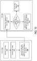
- FIG. 10 is a flowchart illustrating an example embodiment of a process for wirelessly communicating redundant video data streams between a source and a sink using multiple wireless connections.
- FIG. 11 is a flowchart illustrating an example embodiment of a process for wirelessly selecting between multiple redundant video segments at a sink.
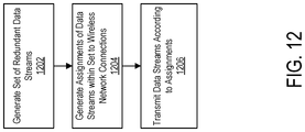
- FIG. 12 is a flowchart illustrating an example embodiment of a process for wirelessly communicating redundant data streams from a source to a sink using multiple wireless connections.
- a remote support system includes a communication system that operates over a plurality of parallel wireless network connections to provide low-latency composite video feeds from vehicle to a remote support server that provides remote support to the vehicle dependent on real-time video.
- the vehicle includes a source that encodes multiple versions of the original video segments (e.g., one per wireless network connection) and transmits the multiple versions of the segments to a sink at the remote support server over the respective wireless connections.
- This redundant multi-path communication system rationally allocates network resources to the managed video streams and balances bandwidth against latency in order to avoid network congestion and safety issues associated with single-path transmissions.
- a similar communication system that transmits video or other real-time messages between a source and a sink may be utilized in cloud robotics applications.
- FIG. 1 is a block diagram of a vehicle environment 100 for a teleoperation or other remote support application.
- the vehicle environment 100 that includes a plurality of vehicles 102 , a remote support server 120 coupled to one or more remote support terminals 110 , and one or more networks 140 comprising network devices 145 .
- the vehicle environment 100 may include different or additional components.
- the vehicle 102 comprises a land vehicle (e.g. a car or truck), a seaborne vehicle, a subterranean vehicle, an airborne vehicle, or other vehicle.
- the vehicle 102 can include, for example, a transport vehicle for transporting passengers or cargo, a surveillance vehicle (e.g., a unmanned aerial vehicle or drone), an operational vehicle such as a forklift or other container yard vehicle, an agricultural vehicle such as a tractor, or any other type of vehicle or robot that can move through an environment.
- a surveillance vehicle e.g., a unmanned aerial vehicle or drone
- an operational vehicle such as a forklift or other container yard vehicle
- an agricultural vehicle such as a tractor, or any other type of vehicle or robot that can move through an environment.
- the vehicle 102 may comprise an intelligent transport system (ITS) that connects to one or more networks 140 and communicates with one or more entities via the one or more networks 140 (e.g., the remote support server 120 and/or other vehicles 102 ) to enable the vehicle 102 to obtain information useful to safe navigation of an environment.
- the vehicle 102 may comprise an autonomous or semi-autonomous vehicle that includes an autonomous driving system that automatically controls navigation based on sensed environment conditions.
- the vehicle 102 may comprise a non-autonomous vehicle that relies on control inputs from a driver in the vehicle 102 or from the remote support server 120 .
- the vehicle 102 wirelessly receives control inputs via the one or more networks 140 that control various components of the drive system such as the steering system, acceleration, braking, etc.
- the vehicle 102 may also comprise various sensors such as optical or infrared cameras, ranging devices such as LIDAR, sonar or radar units, other sensor types allowing real-time acquisition of data on the vehicle environment 100 , vehicle 102 components and occupants, that capture image data and other environmental data that may be streamed over one or more networks 140 to a remote support server 120 or to other vehicles 102 .
- the vehicle 102 may depend on a reliable network connection for streaming video or other sensor data to the remote support server 120 and for receiving control inputs or data used by the vehicle 102 to navigate in a safe and efficient manner. For example, to provide teleoperation support to a vehicle 102 , it is important that the video stream is received at the remote support server 120 in real-time with a latency as low as possible. Therefore, the vehicle 102 may switch between different networks 140 , may switch between different connections to different network devices 145 of the networks 140 , and may maintain multiple simultaneous connections over the same or different networks to optimize its connectivity as described in further detail below.
- the remote support server 120 includes a teleoperation support module 130 that may be implemented as one or more non-transitory computer-readable storage mediums that stores instructions executed by one or more processors to perform the functions attributed herein.
- the teleoperation support module 130 communicates with a vehicle 102 to provide teleoperation or other support services in instances when extra assistance is desired.
- the vehicle 102 may request teleoperation assistance from the teleoperation support module 130 when one or more vehicle sensors fail, when an unknown problem occurs with the vehicle's autonomous driving software, when the vehicle 102 encounters a barrier or other hazardous road conditions, or when a passenger manually requests remote assistance.
- the teleoperation support module 130 may provide teleoperation support when the vehicle 102 enters a geographic region where it is not legally permitted to operate in a completely autonomous way.
- a video stream capturing the vehicle environment may be provided by the vehicle 102 to the teleoperation support module 130 and presented at a remote support terminal 110 .
- a human teleoperator at the remote support terminal 110 may view the video stream on a display to assess the situation and take appropriate action via a control input device at the remote support terminal 110 .
- the teleoperation support module 130 may present real-time video streamed from the vehicle 102 to a display of the remote support terminal 110 and may provide real-time control data to the vehicle 102 received via the remote support terminal 110 to enable the teleoperator remotely drive the vehicle 102 .
- the teleoperation support module 130 may comprise an artificial intelligence agent that does not necessarily require a remote support terminal 110 with a display or physical controls for providing human input.
- the teleoperation support module 130 may provide control instructions to the vehicle 102 directly based on the processing of a real-time video feed and other sensor data streamed to the teleoperation support module 130 from the vehicle 102 without necessarily utilizing any human input.
- the remote support terminals 110 may be coupled to the remote support server 120 via a local area network connection, a direct wired connection, or via a remote connection through the network 140 .
- a remote support terminal 110 may include a display to enable a human teleoperator to view real-time video of the vehicle environment and controls for enabling a human teleoperator to control the vehicle.
- the video may include at least a front view that mimics or approximates the view seen by a driver within the vehicle 102 .
- the video may include additional views, such as a rear view video, side view videos, or other views that may mimic the views seen by a driver in mirrors of a traditional vehicle or may include other views not necessarily available to a driver of a traditional vehicle.
- the controls may include controls that mimic those available within a traditional vehicle such as a steering wheel, acceleration pedal, and brake pedal.
- controls may be available at the remote terminal 110 such as a joystick, mouse, touch screen, voice control system, gesture control system, or other input mechanism to control one or more aspects of the vehicle 102 .
- the remote support terminals 110 may be omitted.
- the remote support server 120 may provide other forms of remote support that do not necessarily involve direct teleoperation, parts of the remote support terminal 110 and the teleoperation support module 130 may be omitted.
- the remote support server 120 may enable remote monitoring without necessarily providing control or remote assistance in which a remote operator provided verbal or message-based information that enables a human driver or automated drive system of the vehicle to make control decisions.
- the remote support server 120 may provide limited control functions such as causing the vehicle 102 to brake or shut off without being able to control other functions such as steering or acceleration.
- the plurality of networks 140 represents the communication pathways between the vehicles 102 , the remote support terminals 110 , and the remote support server 120 .
- the networks 140 use standard communications technologies and/or protocols and can include the Internet.
- the entities on the networks 140 can use custom and/or dedicated data communications technologies.
- the plurality of networks 140 may comprise networks of different types such as, for example, a public cellular connection (e.g., 4G or 5G), a dedicated or private wireless network (e.g., WiFi), a low-latency satellite uplink, VANET wireless channels (including vehicle-to-vehicle or vehicle-to-infrastructure links), or any combination thereof.
- the plurality of networks 140 may include multiple networks of the same type operated by different service providers.
- the networks 140 may include two or more different cellular networks operated by different cellular carriers, having different network parameters, and having different physical infrastructure. Additionally, the networks may include two more WiFi networks operating with different network parameters and/or different network infrastructure.
- the network devices 145 may include cell towers, routers, switches, LEO satellite uplink devices, WiFi hotspot devices, VANET devices, or other components that provide network services to the entities connected to the plurality of networks 140 .
- the network devices 145 may be integrated into roadside infrastructure units that are integrated with traffic devices or other roadside systems.
- the network devices 145 may have varying capabilities and may be spread over a wide geographic area. Thus, different allocations of network resources may be available to vehicles 102 in different locations at different times depending on environmental factors, the capabilities of different network devices 145 , and network congestion in the area where each vehicle 102 is located.
- the network 140 can include peer-to-peer connections between the vehicle 102 and the remote support server 120 or directly with a remote support terminal 110 .
- a server on the network 140 may provide some minimal handshaking to establish the connection and data may then be transmitted to and from the vehicle 102 using a peer-to-peer connection that operates with low latency.
- FIG. 2 is a diagram of an example architecture of a dual-link video transmission system 200 that serves a unidirectional video feed optimized according to particular desired criteria transmitted from a source 210 (sending terminal) to a sink 220 (receiving terminal).
- the source 210 may be embodied in a vehicle 102 and the sink 220 may be embodied in a remote support server 120 that provides remote support to the vehicle 102 based on the captured video.
- the source 210 may comprise a generic connected robot (that is not necessarily a traditional transport vehicle) and the sink 220 may comprise a cloud-based server that obtains video from the robot for monitoring or control applications.
- the dual-link video transmission system 200 operates to provide low latency communications for real-time video transmission under a variety of network conditions.
- the source 210 comprises a camera 201 , two or more video encoders 202 (e.g., encoders 202 - 1 , 202 - 2 ) and two or more communication units 204 (e.g., communication units 204 - 1 , 204 - 2 ).
- the sink 220 comprises two or more communication units 206 (e.g., communication units 206 - 1 , 206 - 2 ), a video processor 207 , and a video module 208 .
- the source 210 and sink 220 may include different or additional components.
- the source 210 and the sink 220 communicate over two or more connections with networks 240 (e.g., networks 240 - 1 , 240 - 2 ) via a plurality of data channels 250 (collectively including the communication unit 204 of the source 210 , the network 240 , and the communication unit of the sink 206 ).
- the networks 240 may at least partially include different types of networks, networks operated by different carriers, networks utilizing different network infrastructure, networks operating according to different network parameter, or networks having other differences that cause performance of each network 240 to vary from each other under different operating conditions.
- the networks 240 may at least partially overlap.
- the networks 240 may partially share some network infrastructure and/or each network 240 may include the Internet. In other embodiments, the networks 240 may share the same infrastructure.
- the different networks 240 - 1 , 240 - 2 represent different concurrently hosted connections between the source 210 and the sink 220 in which performance variations in the data channels 250 may occur due to differences in the communication units 204 , 206 , the connection protocols, or other operating parameters associated with the respective connections.
- the camera 201 generates video frames and provides the video frames to each of the video encoders 202 using a suitable communication technology such as shared memory or domain sockets.
- the video encoders 202 execute in parallel to each encode the received video frame and generate respective encoded video segments each comprising one or more frames.
- the video encoders 202 may each encode the original video frames independently and agnostically of each other, and each transmit the respective encoded segments to different communication units 204 .
- the video encoder 202 - 1 provides an encoded segment to the communication unit 204 - 1 and the video encoder 202 - 1 provides an encoded segment to communication unit 204 - 1 .
- the communication units 204 transmit the respective encoded video segments over respective networks 240 to the sink 220 .
- the transmission over the network 240 may occur over peer-to-peer connections between the source 210 and the sink 220 or any other connection mechanism.
- the communication units 204 may furthermore transmit segment identifiers that identify the segment in the original video.
- the communication units 204 may each include the same segment identifier when transmitting respective encoded segments corresponding to a same set of one or more frames of the original video.
- the segment identifiers may be assigned sequentially, randomly, or otherwise arbitrarily.
- each segment may comprise only a single frame and a different segment identifier is applied for each frame.
- each segment may comprise multiple frames which may be fixed or variable length.
- the communication units 206 receive the respective encoded video segments from each of the networks 240 . Due to variations in encoding, communication protocols, network infrastructure, network congestion, or other differences, the video segments may arrive at the communication units 206 at different times and/or with different quality or other characteristics.
- the video processor 207 receives the video segments from the communication units 206 and determines, for any given segment of the original video (having a unique segment identifier), which of the received encoded segments to provide to the video module 208 . For example, in an embodiment, the video processor 207 may provide the video segment having the earlier arrival time to the video module 208 to minimize latency.
- the video module 208 processes the received video segments.
- the video module 208 may comprise a video renderer that renders video for a remote support terminal 110 or a video processing element of an artificial intelligence agent of a remote support server 120 providing remote support.
- the communication units 204 of the source 210 may comprise a wireless network monitoring unit that supplies quality of service information to the associated video encoder 202 .
- the video encoders 202 may then use this information in conjunction with their own transmission meta information records to adjust video encoding parameters.
- the video encoders 202 may maintain records of data transmission meta information related to the respective outputted data segments.
- the video encoders 202 may store information such as buffer queue length statistics collected in situ or acquired from sources such as the communication units 204 , 206 .
- the meta information may be used by the encoders 202 to dynamically adjust (e.g., in substantially real time) various video encoding parameters such as frame resolution or encoding quality to satisfy (or approach as closely as possible) a set of transmission conditions such as a maximum allowed transmission latency.
- each video encoder 202 may additionally comprise an application programming interface (API) to allow overriding external manipulation of encoding parameters by a high-level decision-making circuit or application coupled the source 210 (e.g., in a vehicle 102 such as a transport vehicle or robot) or a remote computer (e.g., a remote support server 120 or other connected device).
- API application programming interface
- each video encoder 202 may additionally comprise a messaging interface to allow the sink 220 to contribute auxiliary quality of service metrics to the video encoders 202 .
- the remote support server 120 may transmit a message to the vehicle 102 (acting as the source 210 ) to cause the vehicle 102 to increase video encoding quality and to provide a better view to the teleoperator.
- the communication units 206 and the video processor 207 of the remote support server 120 may comprise additional quality of service monitors and transmit a message containing the collected metrics such as packet round trip time, transmission latencies measured for specific bandwidth values, jitter or packet loss and reordering rates to the vehicle 102 (acting as the source 210 ) for consumption by communication units 204 and video encoders 202 .
- each video encoder 202 may additionally comprise conditional programming functions enabling it to adjust video feed parameters proactively.
- the source 210 may additionally comprise a GNSS unit such as GPS receiver and a geospatial database specifying typical cellular carrier bandwidth capacity, WiFi network capabilities, or parameters for other available networks.
- the video encoder 202 may periodically poll the GNSS unit and adjust video encoding parameters based on the rules specified in the database for the detected location. This enables the encoders 202 to automatically adjust encoding quality dependent on expected network conditions as the source 210 moves to different locations.
- the source 210 may additionally comprise other localization technology such as a LIDAR, inertial measurement unit, radio beacon triangulation unit or a computer vision unit and a geospatial database in local or global coordinate systems.
- each video encoder 202 may control the rate of key frames that do not rely on interframe predictions based on detected network conditions. For example, the video encoder 202 may send key frames at a higher rate in low-reliability network conditions in order to reduce the time interval when no valid frames are available if a key frame is lost or corrupted.
- each video encoder 202 may individually encode the chroma and luma components of a video segment.
- the luminosity component of the video segment may be of substantially higher practical value than the chromatic components.
- the video encoder 202 may therefore encode chromatic components at a lower resolution or quality level to prioritize the luminosity components and save bandwidth whenever desirable to compensate for poor network conditions.
- the chromatic components may be discarded by a video encoder 202 entirely and video processor 207 may perform color reconstruction using a machine learning system such as a neural network based entirely or in part on the information available in the luminance component of the video segment.
- each video encoder 202 may additionally first obtain an original frame from the camera 201 in a lower resolution, and then linearly rescale it to a higher resolution before encoding in order to emulate a gradual resolution change.
- FIG. 3 illustrates an example embodiment of a video processor 207 and an example set of inputs and outputs.
- the video processor 207 may comprise a segment ID buffer 309 and a video performance indicator (VPI) unit 310 that evaluates individual video feed segments each comprising one or more frames to select between redundant segments received over the different data channels 250 .
- the VPI unit 310 receives video segments and their respective identifiers (which may be assigned in numeric order or arbitrarily) and selects between corresponding video segments received from the different data channels 250 based on one or more selection criteria. For example, in one embodiment, the VPI unit 310 selects between corresponding segments based on the earliest arrival time.
- the VPI unit 310 compares the identifier of each newly received video segment against a set of identifiers stored in the segment ID buffer 309 of identifiers of previously received video segments that have already been processed and sent to the video module 208 . If the identifier of a newly received video segment is already present in the buffer 309 , the VPI unit 310 discards the video segment. Otherwise, the VPI unit 310 sends the video segment to the video module 208 and stores the identifier to the buffer 309 . For example, as illustrated in FIG. 3 , the VPI unit 310 receives a first segment S1 of a captured video from each of the first data channel 250 - 1 (as S1-1) and the second data channel 250 - 2 (as S1-2).
- the video performance indicator unit 310 determines if the first segment identifier S1 is already in the segment ID buffer 309 .
- the segment S1-1 from the data channel 250 - 1 arrives first.
- the VPI unit 310 recognizes that the segment identifier F1 is not yet in the segment ID buffer 309 .
- the VPI unit 310 then sends the segment S1-1 to the video module 208 and stores the segment identifier S1 to the segment ID buffer 309 .
- the VPI unit 310 determines that the segment identifier S1 is already stored in the buffer 309 and thus discards the redundant segment S1-2.
- the segment S2-2 arrives first from the data channel 250 - 2 .
- the earlier arriving segment S2-2 gets passed to the video module 208 while the later arriving segment S2-1 gets discarded.
- the first received version of the segment S1 is sent to the video module 208 and the other segment is discarded.
- each segment may comprise a single frame and thus the VPI unit 310 may select between the different channels 250 on a frame-by-frame basis.
- the segments may each comprise fixed-length or variable length segments comprising multiple frames.
- a video segment may comprise a heterogeneous sequence of frames or a sequence of interdependent frames.
- a video segment may comprise key frames which contain sufficient information for decoding, and delta frames which additionally utilize information in the most recent key frame and may additionally utilize information in delta frames succeeding the most recent key frame and preceding the current delta frame for decoding.
- the techniques described herein can apply to individual key frames or sequences or segments including delta frames together with additional frames utilized in decoding.
- the segment ID buffer 309 may maintain the maximum identifier number ID max among segments propagated to the video module 208 without necessarily storing every segment identifier. If a newly received segment possesses an identifier ID n ⁇ ID max , the VPI unit 310 may determine that the segment has already been received and discard it. Otherwise, if a received segment has an identifier ID n >ID max , the VPI unit 310 may update ID max in the segment ID buffer 309 and propagate the received from to the video module 208 .
- the video processor 207 may instead select between corresponding segments (having the same original segment identifier) from the different data channels 250 based on characteristics other than their arrival times.
- the video processor 207 may maintain a video performance indicator (VPI) representing a quality index for each video feed computed over one or more segments or a certain duration of time, and select the video feed to be sent to the video module 208 based on the respective VPIs for each feed.
- a first video feed from a first data channel 250 - 1 may initially be set as the active video feed to be propagated to the video module 208 based on the video feed from the first data channel 250 - 1 having a higher VPI than the second video feed from the second data channel 250 - 2 .
- the VPI unit 310 may determine that the VPI of the second video feed from the second data channel 250 - 2 becomes higher than the VPI of the first video feed from the first data channel 250 - 1 . The VPI unit 310 then switches the active video feed to the second video feed from the second data channel 250 - 2 and begins propagating the video feed to the video module 208 .
- the video processor 207 establishes an additive or a multiplicative threshold k that operates as a parameter controlling switching frequency of switching between video feeds from different data channels 250 . For example, if a video feed from data channel 250 - 2 is currently active and has a VPI of B VPI (t) at a time t, the video processor 207 may switch to make the video feed from data channel 250 - 1 active only responsive to the video feed from data channel 250 - 1 obtaining a VPI value of k ⁇ B VPI (t) for a minimum duration of ⁇ t or a minimum number of frames N.
- Such an embodiment may be useful in situations where both wireless networks used possess nearly identical or highly variable characteristics, and the video processor 207 would otherwise be frequently switching between video feeds. Such an embodiment may also be useful to allow time for the buffer bloat that may have accumulated on the previously inactive video feed connection to dissipate.
- the VPI unit 310 may process various other parameters to determine which video feed or segment to select. For example, the VPI unit 310 may base the decision on additional parameters such as the network round-trip time, mean resolution of the last N frames, mean interframe time delta over the last N frames, mean resolution of the last N frames, image naturalness metrics, signal-to-noise ratio, structural similarity indices, standard deviations of these characteristics, or any combination thereof.
- the VPI unit 310 may penalize video feeds with highly variable resolution or interframe delays such that it is more likely to select the more reliable feed in the absence of other distinguishing parameters.
- the VPI unit 310 may maintain one or more video segment buffers (not shown) that stores received video segments.
- the VPI unit 310 assesses the values of the above-described parameters associated with the video segments over the duration of a desired time interval. For example, such an approach may allow the VPI unit 310 to select a video feed providing better visual quality at a cost of introducing latency overhead equal to or longer than the size of the video segment buffer.
- the VPI unit 310 may compute statistical values over an n-size sample from an N-sized array of the most recent frames, where n ⁇ N.
- the sample may be selected using a uniform random distribution function, or it may be selected prioritizing key frames over frames using interframe predictions.
- the video processor 207 additionally comprises an API for a user interface (UI) element allowing a remote human operator or artificial intelligence agent to select the desired video feed and override any automated decision-making process.
- UI user interface
- a UI element may comprise a gesture-tracking system, a hardware button, or a touch-based on-screen switch, or an interface for an artificial intelligence agent.
- FIG. 4 illustrates an example of a communication system 400 for serving bidirectional message streams between a mobile client 401 and a cloud-based controller 408 .
- the mobile client 401 may be embodied in a vehicle 102 that may stream telemetry data and the remote controller 406 may be embodied in a remote support server 120 that provides remote support to the vehicle 102 via a messaging interface.
- Messages passed in one direction e.g., from the mobile client 401 to the remote controller 406
- Messages passed in the opposite direction may represent a command control channel for transmitting command packets or data queries.
- the mobile client 401 may comprise a connected robot
- the remote controller 408 may comprise a cloud-based controller application.
- a message processor 402 duplicates the message and provides the redundant messages to respective communication units 404 together with a message identifier for the message.
- the identifiers may be randomly assigned or may follow a numerical sequence.
- Messages with redundant data are assigned the same message identifiers.
- the communication units 404 each transmit the respective received messages over respective networks 440 that are received by separate communication units 406 as described above.
- the communication units 404 may operate, for example, by setting up routing tables for different physical interfaces on the mobile client 401 .
- the received messages are de-duplicated by the message processor 407 by selecting between the received messages from the different data channels 450 .
- the message processor 407 may select between the messages based on time-of-arrival, quality, or other parameters using any of the techniques described above. For example, the message processor 407 may extract message identifiers and maintain a database thereof similar to the example of FIG. 2 described above. Responsive to receiving a new message, the message processor 407 determines if the message identifier is present in the database. Responsive to a message identifier being present in the message identifier database, the message processor 407 discards the respective message as a duplicate. Otherwise the message is provided to the remote controller 408 . A similar operation may be applied to send messages in the reverse direction from the remote controller 408 to the mobile client 401 .
- the message processors 402 , 407 may assign sequentially growing numerical identifiers to messages being transmitted, with redundant messages being assigned identical identifiers.
- the message processors 402 , 407 may each maintain the maximum identifier number ID max in a message buffer among messages propagated to the respective sink terminals (either the mobile client 401 or remote controller 408 ). Responsive to receiving a message possessing an identifier ID n ⁇ ID max , a message processor 402 , 407 discards the message.
- the message processors 402 , 407 may instead assign randomly generated identifiers to messages, with redundant messages being assigned identical identifiers.
- the message processors 402 , 407 may maintain lists, unordered sets, ring buffers or other data structures of recently received message identifiers. Responsive to receiving a new message, a message processor 402 , 407 determines its identifier and searches for it in the respective list. Responsive to locating the message identifier in the list ID n ⁇ ID 1 , . . . , ID n ⁇ , the message processor 402 , 407 discards the message.
- FIG. 5 illustrates another example of communication system 500 that may be employed in teleoperation or cloud robotics applications.
- a source 510 is equipped with at least three cameras 501 that each stream respective video feeds into a pair of video encoders 502 (i.e., two video encoders 502 per camera 501 ). All of the encoders 502 operate independently of each other.
- Encoders 502 - 1 A, 502 - 2 A, 502 - 3 A are configured to stream their respective outputs over a first data channel 550 -A (which may include a network and communication units of the source 510 and sink 520 as described in FIGS.
- encoders 502 - 1 B, 502 - 2 B, 502 - 3 B are configured to stream their respective outputs over a second data channel 550 -B that may operate with different performance characteristics under different circumstances than the first data channel 550 -A.
- the encoders 502 may each adjust their respective encoding quality, frame type composition, and other parameters according to network feedback and measured performance as described above.
- the video processors 507 each receive a pair of video feeds, one from each of the data channels 550 .
- the video processors 507 process their respective complementary video feeds in the manner described above to selectively output one of the two redundant video segments based on time-of-arrival, quality, or other selection parameter.
- the video processors 507 then supply the selected outputs to the respective visual modules 508 for rendering or other processing.
- the source 510 is further equipped with a drive-by-wire system 518 and the sensor suite 519 .
- a message processor 522 received messages from the drive-by-wire system 518 and sensor suite 519 for sending to the teleoperation console 528 at the sink 520 .
- the message processor 522 duplicates the messages and provides the redundant messages to the respective data channels 550 which each transmit the messages to the message processor 524 at the sink 520 .
- the message processor 524 selects between the messages as described above, and provides the selected message to the teleoperation console 528 .
- the teleoperation console 528 may provide messages to the drive-by-wire system 518 and/or the sensor suite 519 (e.g., including control commands or other data) by sending in messages in the reverse direction in a similar manner.
- each set of encoders 502 associated with a given camera 501 may comprise different encoding formats such as AV1, H.264 or VP8 and/or operate according to different encoding parameters.
- encoders 502 - 1 A, 502 - 2 A, 502 - 3 A may use one encoding format and/or set of encoding parameters while encoders 502 - 1 B, 502 - 2 B, 502 - 3 B may utilize a different encoding format and/or encoding parameters).
- Each video feed may then be encoded by a plurality of encoders 502 with different encoding formats or encoding parameters for transmission to the sink 520 which may affect transmission performance.
- the video processors 507 selects between the redundant video feeds as described above.
- FIG. 6 illustrates another embodiment of a communication system 600 that comprises a network orchestrator 660 linked to a plurality of video encoders 602 and a message processor 611 .
- the data sources e.g., cameras or messaging sources
- the orchestrator 660 collects feedback from the video encoders 602 and message processor 622 and assigns the encoders 602 and the message processor 622 to available data channels 650 based on the feedback in accordance with some optimization criterion.
- the orchestrator 660 may furthermore adjust quality factors associated with the transmitted data based on the feedback.
- the orchestrator 660 may generate assignments such that any given output from one of the encoders 602 and message processor 611 is assigned to two more data channels 650 involving different networks and/or networking parameters. In determining these assignments, the orchestrator 660 may discard possible assignment solutions that involve redundant data feeds being assigned to a common data channel 650 to maintain the effectiveness of data channel redundancy. For example, the orchestrator 660 may operate to ensure that outputs of encoders 602 - 1 A, 602 - 1 B that encode the same video frames from the same camera are assigned to different data channels 650 but may allow encoded video different cameras to be transmitted over the same data channel 650 .
- the orchestrator 660 may acquire network connection parameters and determine the encoding parameters for each video feed encoder. The orchestrator 660 may then perform an optimization algorithm to determine the distribution of encoded video feed streams among the available data channels 650 in a manner that minimizes the total unused bandwidth while maintaining the low latency and smooth playback of the data streams.
- the orchestrator 660 maintains three or more data channel assignments for one or more data sources. Such an approach allows the orchestrator 660 to increase redundancy and reliability of critically important data streams at the expense of bandwidth available for allocation to secondary data streams.
- the orchestrator 660 may statically (e.g. during initialization) or dynamically (e.g. during operation) set the redundancy level for individual data sources or data source groups.
- the orchestrator 660 may additionally comprise an API permitting control over redundancy level to an external decision-making process, including both automation and human intervention.
- the orchestrator 660 executes a search process in the space of configuration states described hereinafter.
- the search process may use an applicable state of the art search algorithm such as A*, D*, greedy depth-first search or Dijkstra's algorithm, or other algorithm.
- the orchestrator 660 additionally may communicate the solution in full or in part to the encoders 602 or message processor 622 , which may then reroute their traffic flows through the appropriate data channels 650 that may each transmit over different networks and/or utilize different network parameters.
- the orchestrator 660 may repeat the search process on a regular basis or on triggering of certain events.
- the orchestrator 660 represents the edges of the graph comprising the space of configuration states reachable from a particular state by specific actions that may be taken by the orchestrator 660 , the encoders 602 , or message processor 622 .
- such actions may include a null assignment of video data to a data channel 650 to effectively stop the video feed, or changing the video feed resolution.
- the orchestrator 660 represents a state of the communication system 600 possessing 2n dually redundant data channels and k data channels 650 with a 2n length vector of base (k+1) numbers.
- Vector element values determine the identifier of the assigned data channel 650 .
- the additional degree of freedom corresponds to the option of assigning an output to a null data channel, i.e. stopping its streaming.
- the state of the communication system 600 additionally includes a 2n length vector determining the quality property of each data stream.
- an element describing the quality level of a video stream may determine the currently set resolution of the camera video feed.
- the first addend g(s) represents costs incurred by a chosen action (such as reassigning a data stream to a different network or changing its quality factor), while the second addend h(s) represents the heuristic function used to rank candidate states.
- B i max is the practical maximum bandwidth that may be consumed by the data stream i
- B(i, s) exp is the empirically measured bandwidth as provided by the data stream producer.
- the orchestrator 660 constructs and updates the state graph episodically, periodically or in substantial real-time according to the availability of experimental data acquired by a mobile client or a plurality thereof.
- the orchestrator 660 does not distinguish in advance between a set of states ⁇ s ij (L, M, C, H j ) j ⁇ J ⁇ comprised of identical vectors aside from the hidden variable vectors H j .
- the orchestrator 660 is thus capable of distinguishing between the states ⁇ s ij j ⁇ J ⁇ post-factum by applying an action Q or a sequence thereof, as otherwise the states can be practically considered a single state.
- the state graph may be updated by performing posterior analysis of the observed penalties and constructing the sets of states ⁇ s ij (L, M, C, H j ) j ⁇ J ⁇ for all directly observable state identifiers i ⁇ I. Penalties associated with such ambiguous states may be computed as the mathematical expectation of the penalty according to measured probabilities of each state.
- the state graph may be represented with a hidden Markov model.
- filtration of non-persistent features of state graph may be performed episodically or periodically to remove states that are not observed sufficiently often and are similar enough to some other states to be merged with them. With this approach, the search algorithm performance will be improved, which may be important for a solution that is required to execute in substantial real time. To perform the filtration, techniques such as persistent homology may be used, allowing to investigate graph structure at various cut-off weight thresholds.
- the B i max values used to evaluate penalties may comprise dynamic variables depending on the geographical coordinates of the source or an equivalent positioning vector, and a vector T comprised of the time since Epoch modulo durations representing periods of diurnal, annual, or other variations, or an equivalent representation of the local time and the day of the year.
- the orchestrator 660 may artificially limit the total number of opened states or the search depth level for performance considerations. For example, the orchestrator 660 may impose the search depth limit manually and statically, or in a periodic manner based on the current CPU load. In this case the orchestrator 660 uses the state with the best heuristic function value seen during the search procedure as the search result.
- the orchestrator 660 may impose penalties on individual data channels in order to restrict bandwidth consumption.
- Exact penalization mechanisms may vary; for example, a video channel may be penalized by limiting the maximum permitted resolution, and an audio channel may be penalized by allowing a higher ratio of dropped frames.
- the orchestrator 660 may restrict the solution space to a subset of states where the ratio of penalty values for any pair of redundant data channels is limited by a predefined interval.
- each video encoder 602 publishes the estimate of the available bandwidth and other relevant channel metadata in substantially real time for consumption by the orchestrator 660 or, optionally, other functional units of the communication system 600 .
- the orchestrator 660 subscribes to metadata updates published by all encoders 602 ; responsive to obtaining a metadata update the orchestrator 660 may subsequently include the changes into aggregated metadata, assess the current available bandwidth for each wireless network, and perform the search procedure to maximize the network utilization and reduce congestion.
- the orchestrator 660 performs metadata aggregation and solution search procedure on a regular basis by polling some or all encoders 602 for the current values of metadata variables, rebuilding the aggregate metadata array and performing the search procedure.
- the interval at which the orchestrator 660 repeats this cycle may be adjusted depending on decisions produced by a higher order governor unit. For example, a contentious dynamic network environment used by multiple highly mobile clients may require a more frequent cycle to allow for optimal use of resources compared to a sparsely populated network environment with gradually changing characteristics.
- the orchestrator 660 determines the cost function in part using a priority coefficient manually or programmatically assigned to each data or video stream.
- the highest priority coefficient may be assigned to the fore camera, the second highest to the command and telemetry channel, and then in diminishing order to side camera feeds, rear camera feeds, and audio streams.
- the orchestrator 660 additionally comprises a high-order governor unit which manipulates the priority values depending on the environment and the current task being executed by the mobile client.
- the orchestrator 660 may assign higher priority to the rear camera feeds when the vehicle is driving in reverse gear.
- the orchestrator 660 may use the priority coefficient as an additive or multiplicative factor determining the bandwidth penalty a data channel is allowed to incur in case of shortage of bandwidth. Subsequently, information feeds of lower priority would be penalized more severely to preserve uncongested network operation.
- the fore camera video feed may be assigned a higher priority coefficient than side camera feeds, ensuring that its bandwidth consumption is regulated less aggressively.
- a data channel 650 dedicated to transmission of safety-critical commands such as braking orders may be assigned a specially encoded infinite priority value to prevent the system from attempting to regulate that data channel 650 in any manner.
- the orchestrator 660 in part determines the cost function using a penalization order sequence to prevent penalization of a data stream until one or more practically less important data streams have been penalized to the maximum extent permitted by their priority coefficients.
- the orchestrator 660 in part determines the cost function using the specific penalization currently applied to a channel and the difference between its current penalization level and the prospective penalization level in the candidate solution.
- the heuristic may favor a layout modification that among two complementary data channels would benefit the one that is currently more penalized.
- the orchestrator 660 in part determines the cost function using the specific penalization currently applied to a channel in a non-linear manner such as via a logistical function, with its shape and parameters being chosen according to the specific minimum requirements of available data channels 650 .
- Such an implementation may be useful to prevent individual data channels from being starved out of bandwidth by high-priority ones.
- FIG. 7 illustrates an example of an enhanced video communication system 700 .
- the orchestrator 660 manages video streams from cameras 701 .
- the encoders 602 encode mutually complementary (e.g., redundant) streams to which the orchestrator 660 assigns to data channels 650 using any of the above-described techniques.
- the video processors 707 evaluate the received video data and output selected segments to the video modules 708 using any of the above-described techniques.
- the video processors 707 maintain and update a ranking of each version of the video feed in substantially real time, provide segments from the high-ranking version of each feed to the video consumer for further processing, and discard segments from the low-ranking version of each feed.
- the orchestrator 660 may furthermore update the assignments based on monitored network parameters.
- the network orchestrator 660 may determine to detach the stream generated by the camera 701 - 3 from the data channel 650 -C and processed by the encoder 602 - 3 B and re-assign it to data channel 650 -B instead.
- the network orchestrator 660 switches an inactive video stream assigned to a null network to a low-bitrate mode by instructing a respective encoder 602 to reduce the video feed resolution or quantization parameter (QP) instead of completely suspending transmission.
- the inactive video stream is maintained as a backup feed available immediately in case of a failure affecting the primary video stream at the cost of computational resources utilized to continue encoding and decoding the video feed.
- the orchestrator 660 may instruct a respective encoder 602 to maintain the bitrate of the backup video feed or increase it depending on the wireless network performance.
- the network orchestrator 660 transforms an inactive video stream into a probe stream by instructing a respective encoder 602 to strip the payload data from the respective network packets, and optionally mark them as dummy packets.
- the respective communications units associated with the data channels 650 may use an inactive video stream for collecting high-frequency wireless network metrics while conserving bandwidth consumption.
- the video encoders 602 strip payload data from delta frames but transmit key frames normally, or transmit short bursts of key frames and delta frames normally but strip the payload from most packets, or use another method of mixing probe and payload packets.
- Such an embodiment may allow the system to improve the network assessment quality, calibrate the respective encoders 602 to true network conditions, and to prevent upstream network routers (e.g., controlled by cellular carrier or WiFi administrators) from marking a video stream as low-bitrate and restricting potentially available bandwidth.
- a video processor 707 builds the output video feed by filtering dummy packets from the mutually complementary streams.
- a video encoder 602 responsive to the network orchestrator 660 activating a video stream, gradually increases the bitrate of the video stream by manipulating the payload-to-dummy ratio (PDR), resolution (WXH) or QP.
- PDR payload-to-dummy ratio
- WXH resolution
- QP QP
- the system aims for Pareto-optimality of QP, resolution and PDR.
- Pareto-optimality in this case is interpreted as a condition whereas a quality metric (QM) of the video feed cannot be improved under the given bitrate constraints by improving one or more of the tracked parameters without detrimentally affecting one or more other tracked parameters.
- QM quality metric
- a video encoder setting described by a (WXH, QP, PDR) triplet that produces a video feed possessing the maximum QM value of video feeds produced by all encoder settings at a given bitrate restriction is considered to be Pareto-optimal.
- Other video encoder settings may be used to define the Pareto optimality frontier.
- the system may additionally implement roaming in scenarios where such are not provided by the available wireless connectivity environment.
- One or more communications units of the data channels 650 are allocated to probing available WiFi, cellular or other spatially distributed wireless access nodes. Responsive to detection of a wireless access node possessing better connection quality metrics than one of the currently utilized wireless access nodes and determination with a high degree of confidence that the current trajectory of source 600 represented by a mobile unit is not likely to lead to its performance degradation within a desired time interval, the network orchestrator 660 may proactively reassign an inactive video feed to that wireless access node.
- probing of available WiFi nodes may be performed using one or more underutilized communication units 204 or by communication units 204 serving inactive video feeds.
- FIG. 8 illustrates examples of possible solution spaces for an orchestrator 660 that orchestrates assignment of complementary data streams to two possible data communication channels 801 , 802 .
- the data streams include the following complementary data stream pairs where each pair represents a set of redundant video streams: ⁇ C1A, C1B ⁇ , ⁇ C2A, C2B ⁇ , ⁇ C3A, C3B ⁇ , ⁇ C4A, C4B ⁇ , ⁇ C5A, C5B ⁇ , ⁇ C6A, C6B ⁇ and a set of redundant data streams ⁇ DCA, DCB ⁇ .
- the solution space enforces assignment of streams within the same complementary pair to different data channels 801 , 802 .
- the solution space comprises 128 homomorphic solutions, of which one example solution is illustrated in FIG. 6 .
- an orchestrator 660 may assign a set of complementary data streams to three or more different data channels 801 , 802 under the same constraint that the streams within the same complementary pair are assigned to different data channels.
- the same set of complementary data stream pairs specified above are assigned between three data communication channels 803 , 804 , 805 .
- the candidate space for distributing video and data channels between data communication channels 803 , 804 , 805 comprises 279,936 homomorphic solutions on which one is illustrated.
- an orchestrator 660 may orchestrate assignment of data streams that are triple redundant or have even higher redundancy between an arbitrary number of data communication channels using similar techniques those described above.
- FIG. 9 illustrates an example embodiment of a process performed by a simulation suite to model network performance, generate policy for orchestrators 660 based on the modeled network performance, and distribute the policy.
- the method may partially comprise a reinforcement learning approach, where the orchestrator 660 is initially trained on a dataset collected using a wireless environment and the urban traffic model simulation suite.
- the simulation suite may involve, for example, the SUMO traffic simulator, LENA/ns-3 LTE network simulator, and the NS2Mobility middleware package, or any appropriate alternatives thereof.
- the simulator retrieves 901 geospatial information including positions and shapes of obstacles such as hills and buildings in an environment.
- the simulator furthermore retrieves 902 the location, orientation and technical characteristics of cellular transmitter nodes or other network infrastructure, and instantiates a simulation using geospatial information representing the urban domain or other environment.
- the simulator then simulates 903 operation of the vehicle either over a plurality of specific routes (such as routes acquired from the database of routes previously traversed by an actual vehicle being simulated), and/or simulates 904 operation of the vehicle over a randomly chosen route for a substantial duration of time.
- the simulator may then update 905 a configuration of an orchestrator policy based on the simulated results. For example, the simulator may select an assignment schema of R ⁇ D and specific values for C in a manner determined by a comparison of an accepted exploration and an exploitation policy.
- the simulator determines 906 if the exploration process is complete.
- the simulator exports 907 a policy model.
- the policy model may comprise, for example, a tabular rule set or a trained neural network rule set for configuring and assigning data streams in each state corresponding to a road segment under investigation.
- a state in such a simulation may be determined by the localization vector comprised of vehicle position, speed, heading and steering angle ⁇ x, y, v, ⁇ , ⁇ or a subset thereof, the map of data stream assignment to communication devices ⁇ r ij ⁇ d k k ⁇ [0, m], i ⁇ [1, n], j ⁇ [1,2] ⁇ , and data stream configurations ⁇ c 1 i ⁇ [1, n] ⁇ .
- Performing an orchestrator action may be interpreted as altering the course of the ITS in the state space, potentially allowing it to reach a state (S, Q) ⁇ S′ is associated with the prospective vehicle localization vector and possessing a lower cost function compared to the state (S, ⁇ ) S′′.
- the simulation suite may involve other simulation software and data source classes to simulate WiFi signal propagation in indoors environments.
- a simulation suite involving Omnet++ or MIMIC technologies and an environment built on an imported or procedurally generated dataset describing the geometry of a warehouse or a container yard may substitute the hereinbefore described simulation suite and perform an equivalent workflow in order to generate policies for orchestrators 660 operating on utility vehicles such as forklifts or pallet jacks deployed in an actual or a model warehouse.
- the simulator suite may additionally comprise simulations of specific or randomly generated urban traffic scenarios, and perform policy training for each desired urban traffic scenario, local time interval, or a cluster thereof.
- the vehicle localization vector may be additionally enriched by variables such as the time derivatives of the steering angle ⁇ dot over ( ⁇ ) ⁇ and vehicle speed ⁇ dot over (v) ⁇ .
- the orchestrator 660 may use this approach to react to actions performed by a teleoperator in advance.
- the cost function F(S, Q) may be integrated over a time interval ⁇ t to account for the fact that orchestrator 660 actions are not instantaneous and possess a cooldown period, during which no new actions may be taken. From this, it follows that in an example, the orchestrator 660 configuration for a time interval where the vehicle may partly possess good wireless connectivity and partly be located in a radio shadow may be chosen according to the integral cost function in a risk-averse manner, i.e. sacrificing the additional bandwidth that may be obtained in the first part of the period in order to avoid incurring heavy penalties in the second part of the period.
- the constructed policy is comprised of a neural network possessing at least one hidden layer, where the input state is determined by the vehicle localization vector, data stream assignment to communication devices and data stream configurations, and the output layer is comprised of an (2n ⁇ m) ⁇ m mapping of complementary data streams to communication devices combined with the unrolled dense matrix of data stream configuration options.
- the architecture of the neural network may be determined either manually or using the automated machine learning approach.
- the neural network training process is comprised of three stages. During the first stage, the neural network is trained regularly. During the second stage, pruning of the resulting neural network is performed. During the third stage, the training process is repeated using the pruned network architecture.
- the simulator suite distributes 908 the orchestrator policy to computational units to perform the actions onboard without requiring additional input from a remote machine intelligence agent.
- the simulator suite may update onboard policies episodically, periodically, or in substantial real time.
- the policy distribution process may involve either simultaneous transmission of a plurality of policy models produced for different scenarios, or on-demand transmission of the policy model determined as the currently most appropriate one.
- the policy selection process performed onboard the vehicle or at the remote server may utilize information acquired by the vehicle sensor suite, information acquired from third party data sources, or both.
- the simulation suite utilizes a generalized multi-layer wireless network environment representation possessing the desired set of characteristics to perform the required simulations, and does not involve traffic simulations.
- the characteristics of wireless networks are present explicitly in the input vector of the policy model as opposed to being present implicitly as the product of the vehicle's localization vector and interference generated by other network clients present in the simulation.
- the simulation suite determines systematic simulation errors using a cross-verification procedure.
- the simulation suite may initially use a plurality of network traces obtained from experimental results as a reference for establishing the time profile of network bandwidth bottleneck.
- the simulation suite may replay the exact sequence of actions taken by a simulated orchestrator 660 during the recorded network trace, and the simulated data sources may replay the recorded data streams such as uncompressed video feeds for consumption by the encoders.
- the simulation suite may then use the root mean squared error of the recorded video encoder bit rates and the simulated video encoder bit rates or any other applicable metric over the time interval covered by the network trace to establish the systematic error, which may then be accounted for in future simulation runs.
- the simulation suite performs the training of the orchestrator 660 based on experimental results.
- the simulated orchestrator 660 may then select and apply an updated array of configuration variable sets C, measure and record the resulting cost function.
- the remainder of the learning process is similar to the one described hereinbefore.
- the collection of variables determining the state space may include spatial or spatiotemporal position of the vehicle P.
- the position P may be determined in part by the current geographical coordinates of the vehicle, its current pluscode or H3 index at the desired resolution level, or the current local time.
- the collection of variables determining the state space may include both spatial or spatiotemporal position of the vehicle and the wireless network characteristics. Such an approach may allow the simulation suite to build a more comprehensive model reflecting a better tuned and nuanced state-action database.
- the simulation suite accounts for the differences in vehicle types during data accumulation process and orchestrator training.
- the simulation suite may create and maintain distinct experimental or simulated data sets for each individual vehicle model supported to account for differences in driving experience for remote operators.
- the simulation suite may create and maintain experimental or simulated data sets for vehicle clusters possessing similar kinematic qualities or characteristics of the command and control response function.
- the specific criteria used to establish vehicle clusters may be chosen according to a desired objective function, according to operator feedback, or otherwise. Subsequently, an individual vehicle would have the orchestrator policy appropriate for its class loaded into its memory.
- the simulation suite may perform vehicle model clustering episodically, periodically or in substantial real time depending on the chosen criteria. For example, a vehicle model may be transitioned from one cluster to another overriding the algorithmic selection by a qualifier supervisor based on feedback received from human operators. Alternatively, changes in wireless network characteristics, data stream encoding protocols or addition of new supported vehicle models may enable achieving a lower variance between optimal solutions and the unified cluster-wide solution.
- the model construction workflow involves a transfer learning or domain adaptation process to accelerate the production of orchestrator models by utilizing one model trained for a specific cluster as a basis for training models corresponding to other clusters or to an updated version of the original cluster.
- a model corresponding to an vehicle cluster describing autonomous passenger cars may be transferred to a cluster describing delivery robots using state of the art techniques.
- the simulation suite may perform a dimensionality reduction procedure prior to conducting model training for each vehicle model cluster individually.
- a policy model for delivery robots may be pruned of the vehicle speed variable, as the maximum speed attained by such vehicles is negligible compared to the adaptation capabilities of industry-standard communication devices.
- the simulation suite may partially comprise an expert-driven input module.
- remote operators may provide feedback using any suitable interface or mechanism and rate road segments according to the vehicle operation difficulty level encountered. Such feedback may also be obtained independently by measuring physiological characteristics such as heart beat rate, eye-blink rate, skin conductance, eye pupil dilation or constriction, and limb motion deviation from standard models.
- This manually or semi-manually labeled data may subsequently be used as an input vector for the orchestrator policy neural network. This approach may account for interconnected factors affecting remote operator performance that may be difficult to correctly quantify and formalize.
- the simulation suite may additionally comprise a video feed quality assessment module, and use the output of that module as a part of the input vector for training the orchestrator neural network.
- the simulation suite may additionally comprise a video feed complexity assessment module to estimate the effort required on the part of a remote operator for correctly perceiving and comprehending the visual scene.
- a video feed complexity assessment module to estimate the effort required on the part of a remote operator for correctly perceiving and comprehending the visual scene.
- a module may be built around a deep convolutional neural network trained to detect obstacles and a subsystem for estimation of obstacle kinematics. The output of such a module may be further used as a part of the input vector for training the orchestrator neural network.
- FIG. 10 illustrates an example embodiment of a process for wirelessly communicating low latency video from a source 1050 (e.g., a teleoperated vehicle or other robot) to a sink 1060 (e.g., a remote support server or other processing server).
- a connection is established 1002 between the source 1050 and the sink 1060 .
- This connection may comprise, for example, a connection between a vehicle 102 and a remote support server 120 providing teleoperation services, a connection between a robot and a cloud processing server, or other application.
- the source receives a video feed and encodes 1004 the video feed to generate a set of two more encoded video segments having redundant video data.
- a first encoder encodes a first video segment to generate a first encoded video segment
- a second encoder encodes the first video segment to generate a second encoded video segment that includes redundant video data to the first encoded video segment.
- more than two encoded video segments may be generated.
- the encoded video segments are transmitted 1006 over different respective wireless network connections.
- a first communication unit transmits the first encoded video segment over a first wireless network connection
- a second communication unit transmits the second encoded video segment over a second wireless network connection.
- Other embodiments may include more than two communication units that each transmit over different wireless networks connections.
- the different wireless network connections may operate according to different communication parameters, may be facilitated by different networks with different underlying network infrastructure, and/or may have varying performance characteristics that differently affect signal transmission of the different encoded video segments.
- a video processor receives 1008 the encoded video segments together with segment identifiers for the video segments. As each video segment is received at the sink 1008 , a video processor determines 1010 if the segment identifier is present in a segment ID buffer. If the segment identifier is not present in the segment identifier buffer, the video processor stores 1012 the segment identifier to the segment identifier buffer and provides the encoded video segment to a video module. If the video processor determines that the segment identifier is present in the segment identifier buffer, the video processor discards 1014 the second encoded video segment. In the process of FIG. 10 , each video segment may comprise either a single frame or a set of multiple frames.
- FIG. 11 illustrates an alternative embodiment of a process performed at a sink 1060 for selecting between received video segments.
- a video processor receives 1102 video segments from the multiple different network connections and determines 1104 VPIs for each segment within a set of corresponding segments.
- the corresponding segments comprise segments encoded from the same original video segment and transmitted over different wireless network connections that may have different performance parameters.
- the VPIs may represent, for example, a quality measure, a latency measure, or other characteristic that may vary between segments due to the different network performance characteristics.
- the video processor determines 1106 a selected video segment selected based on the respective VPIs, and outputs 1108 the selected video segment to a video device.
- FIG. 12 illustrates another embodiment of a process for transmitting data over a plurality of wireless network connections from a source to a sink.
- a source generates 1202 a set of redundant data streams and a network orchestrator generates 1204 assignments for transmitting the set of redundant data streams over multiple different network connections that may have varying performance characteristics.
- the assignments are made so that each data stream within a redundant set is assigned to a different network connection, and may be based on one or more optimization criteria.
- a plurality of communication units transmits 1206 the respective plurality of data streams over the multiple wireless network connections based on the assignments.
- the wireless communication system described herein can apply to general remote support applications for robotics where low latency communications are desirable under varying network conditions.
- the communication system may be employed in various cloud robotics applications.
- a robot may stream image or video data to an artificial intelligence server that performs real-time or substantially real-time content recognition.
- Such applications may be useful for inventory management, monitoring, security, or other robotics applications.
- Certain aspects of the embodiments include process steps and instructions described herein in the form of an algorithm. It should be noted that the process steps and instructions of the embodiments can be embodied in software, firmware or hardware, and when embodied in software, could be downloaded to reside on and be operated from different platforms used by a variety of operating systems. The embodiments can also be in a computer program product which can be executed on a computing system.
- the embodiments also relate to an apparatus for performing the operations herein.
- This apparatus may be specially constructed for the purposes, e.g., a specific computer, or it may comprise a computer selectively activated or reconfigured by a computer program stored in the computer.
- a computer program may be stored in a computer readable storage medium, such as, but is not limited to, any type of disk including floppy disks, optical disks, CD-ROMs, magnetic-optical disks, read-only memories (ROMs), random access memories (RAMs), EPROMs, EEPROMs, magnetic or optical cards, application specific integrated circuits (ASICs), or any type of media suitable for storing electronic instructions, and each coupled to a computer system bus.
- Memory can include any of the above and/or other devices that can store information/data/programs and can be transient or non-transient medium, where a non-transient or non-transitory medium can include memory/storage that stores information for more than a minimal duration.
- the computers referred to in the specification may include a single processor or may be architectures employing multiple processor designs for increased computing capability.
- Coupled along with its derivatives.
- the term “coupled” as used herein is not necessarily limited to two or more elements being in direct physical or electrical contact. Rather, the term “coupled” may also encompass two or more elements are not in direct contact with each other, but yet still co-operate or interact with each other, or are structured to provide a thermal conduction path between the elements.
- the terms “comprises,” “comprising,” “includes,” “including,” “has,” “having” or any other variation thereof, are intended to cover a non-exclusive inclusion.
- a process, method, article, or apparatus that comprises a list of elements is not necessarily limited to only those elements but may include other elements not expressly listed or inherent to such process, method, article, or apparatus.
Abstract
Description
P i(s)=B i max −B(i,s)exp
Claims (20)
Priority Applications (3)
| Application Number | Priority Date | Filing Date | Title |
|---|---|---|---|
| US16/862,513 US11223667B2 (en) | 2019-04-30 | 2020-04-29 | Low latency wireless communication system for teleoperated vehicle environments |
| US17/540,095 US11799936B2 (en) | 2019-04-30 | 2021-12-01 | Low latency wireless communication system for teleoperated vehicle environments |
| US18/472,140 US20240015196A1 (en) | 2019-04-30 | 2023-09-21 | Low latency wireless communication system for teleoperated vehicle environments |
Applications Claiming Priority (2)
| Application Number | Priority Date | Filing Date | Title |
|---|---|---|---|
| US201962841194P | 2019-04-30 | 2019-04-30 | |
| US16/862,513 US11223667B2 (en) | 2019-04-30 | 2020-04-29 | Low latency wireless communication system for teleoperated vehicle environments |
Related Child Applications (1)
| Application Number | Title | Priority Date | Filing Date |
|---|---|---|---|
| US17/540,095 Continuation US11799936B2 (en) | 2019-04-30 | 2021-12-01 | Low latency wireless communication system for teleoperated vehicle environments |
Publications (2)
| Publication Number | Publication Date |
|---|---|
| US20200351322A1 US20200351322A1 (en) | 2020-11-05 |
| US11223667B2 true US11223667B2 (en) | 2022-01-11 |
Family
ID=73015993
Family Applications (3)
| Application Number | Title | Priority Date | Filing Date |
|---|---|---|---|
| US16/862,513 Active US11223667B2 (en) | 2019-04-30 | 2020-04-29 | Low latency wireless communication system for teleoperated vehicle environments |
| US17/540,095 Active 2040-08-13 US11799936B2 (en) | 2019-04-30 | 2021-12-01 | Low latency wireless communication system for teleoperated vehicle environments |
| US18/472,140 Pending US20240015196A1 (en) | 2019-04-30 | 2023-09-21 | Low latency wireless communication system for teleoperated vehicle environments |
Family Applications After (2)
| Application Number | Title | Priority Date | Filing Date |
|---|---|---|---|
| US17/540,095 Active 2040-08-13 US11799936B2 (en) | 2019-04-30 | 2021-12-01 | Low latency wireless communication system for teleoperated vehicle environments |
| US18/472,140 Pending US20240015196A1 (en) | 2019-04-30 | 2023-09-21 | Low latency wireless communication system for teleoperated vehicle environments |
Country Status (3)
| Country | Link |
|---|---|
| US (3) | US11223667B2 (en) |
| EP (1) | EP3939302A4 (en) |
| WO (1) | WO2020223414A1 (en) |
Families Citing this family (17)
| Publication number | Priority date | Publication date | Assignee | Title |
|---|---|---|---|---|
| US10479356B1 (en) | 2018-08-17 | 2019-11-19 | Lyft, Inc. | Road segment similarity determination |
| US11928557B2 (en) | 2019-06-13 | 2024-03-12 | Lyft, Inc. | Systems and methods for routing vehicles to capture and evaluate targeted scenarios |
| US11449475B2 (en) | 2019-06-28 | 2022-09-20 | Lyft, Inc. | Approaches for encoding environmental information |
| US11157007B2 (en) * | 2019-06-28 | 2021-10-26 | Lyft, Inc. | Approaches for encoding environmental information |
| US11245742B2 (en) * | 2019-07-19 | 2022-02-08 | Juniper Networks, Inc | Apparatus, system, and method for flow-level switchover of video streams |
| US11788846B2 (en) | 2019-09-30 | 2023-10-17 | Lyft, Inc. | Mapping and determining scenarios for geographic regions |
| US11816900B2 (en) | 2019-10-23 | 2023-11-14 | Lyft, Inc. | Approaches for encoding environmental information |
| US11283695B2 (en) * | 2020-04-21 | 2022-03-22 | Aviatrix Systems, Inc. | System and method for determination of network operation metrics and generation of network operation metrics visualizations |
| EP3930287A1 (en) * | 2020-06-24 | 2021-12-29 | Sandvine Corporation | System and method for managing adaptive bitrate video streaming |
| CN112770353B (en) * | 2020-12-30 | 2022-10-28 | 武汉大学 | Method and device for training congestion control model and method and device for controlling congestion |
| CN114827942A (en) * | 2021-01-29 | 2022-07-29 | 伊姆西Ip控股有限责任公司 | Method, electronic device and computer program product for data transmission |
| CN113141415B (en) * | 2021-05-07 | 2023-05-12 | 广州小鹏汽车科技有限公司 | Remote driving system and method for vehicle, electronic device and storage medium |
| CN113347421B (en) * | 2021-06-02 | 2023-07-14 | 黑芝麻智能科技(上海)有限公司 | Video encoding and decoding method, device and computer equipment |
| CN113726463B (en) * | 2021-08-23 | 2023-11-17 | 山东交通学院 | Broadband wireless channel modeling method based on finite state Markov |
| CN117400959A (en) * | 2022-07-07 | 2024-01-16 | 腾讯科技(深圳)有限公司 | Remote driving control method and device, computer readable medium and electronic equipment |
| CN115474077A (en) * | 2022-09-06 | 2022-12-13 | 一汽解放汽车有限公司 | Video transmission method and device, vehicle-end controller and storage medium |
| US11936700B1 (en) * | 2023-02-16 | 2024-03-19 | GM Global Technology Operations LLC | Vehicle video streaming system and method |
Citations (26)
| Publication number | Priority date | Publication date | Assignee | Title |
|---|---|---|---|---|
| JP2009284149A (en) | 2008-05-21 | 2009-12-03 | Panasonic Corp | Image encoding processing apparatus |
| US20100033622A1 (en) * | 2004-03-24 | 2010-02-11 | Erwin Bellers | Multiple description coding video transmission using de-interlacing mechanisms |
| US20120013637A1 (en) * | 2000-02-11 | 2012-01-19 | Spny Electronics, Inc. | Automatic color adjustment of a template design |
| WO2012013637A1 (en) | 2010-07-30 | 2012-02-02 | Thales | Method for configuring an adaptive source encoder based on a prediction of future transmission conditions, and terminal and system implementing the method |
| US20120137319A1 (en) | 2010-11-29 | 2012-05-31 | Time Warner Cable Inc. | Technique for usage forecasting in a switched digital video system |
| US20120180101A1 (en) | 2011-01-10 | 2012-07-12 | Davis Scott M | Quality feedback mechanism for bandwidth allocation in a switched digital video system |
| US20120317308A1 (en) * | 2011-06-10 | 2012-12-13 | Bytemobile, Inc. | On-demand adaptive bitrate management for streaming media over packet networks |
| US20120320916A1 (en) | 2011-06-14 | 2012-12-20 | Viasat, Inc. | Transport protocol for anticipatory content |
| US20130094522A1 (en) | 2011-10-17 | 2013-04-18 | Mehran Moshfeghi | Method and system for utilizing multiplexing to increase throughput in a network of distributed transceivers with array processing |
| US20130133028A1 (en) * | 2009-01-28 | 2013-05-23 | Headwater Partners I Llc | Automated device provisioning and activation |
| US20130246577A1 (en) | 2012-03-15 | 2013-09-19 | International Business Machines Corporation | Connection management and optimization for services delivered over networks |
| US20140025648A1 (en) | 2010-02-22 | 2014-01-23 | Data Accelerator Ltd. | Method of Optimizing Data Flow Between a Software Application and a Database Server |
| US20150145944A1 (en) * | 2012-01-03 | 2015-05-28 | Qualcomm Incorporated | Exchanging portions of a video stream via different links during a communication session |
| US20150201023A1 (en) | 2014-01-16 | 2015-07-16 | Dominic M. Kotab | System, method, and computer program product for the directing and distributing of media content |
| US20150271500A1 (en) * | 2014-03-24 | 2015-09-24 | Sony Corporation | Information processing apparatus, information processing system, information processing method, and program |
| US20160066357A1 (en) * | 2014-08-30 | 2016-03-03 | Mariana Goldhamer | Transmission of uncompressed video in cellular networks |
| US20160227017A1 (en) | 2015-01-29 | 2016-08-04 | Dominic M. Kotab | System, method, and computer program product for managing a network based on feedback |
| US20160323652A1 (en) | 2012-12-27 | 2016-11-03 | Echostar Technologies L.L.C. | Enhanced reliability for satellite data delivery |
| US20160381110A1 (en) | 2015-06-23 | 2016-12-29 | Facebook, Inc. | Streaming media presentation system |
| US20170048328A1 (en) | 2015-08-13 | 2017-02-16 | Acronis International Gmbh | Optimization of packetized data transmission in tcp-based networks |
| US20170251515A1 (en) * | 2014-09-08 | 2017-08-31 | Liveu Ltd. | Methods and systems for managing bonded communications across multiple communication networks |
| US9806988B2 (en) | 1996-10-31 | 2017-10-31 | Patentmarks Communications, Llc | Multi-protocol telecommunications routing optimization |
| US20180123963A1 (en) | 2016-10-31 | 2018-05-03 | Cisco Technology, Inc. | Optimized channel selection for virtual access point (vap) enabled networks |
| US20180218073A1 (en) | 2015-07-08 | 2018-08-02 | Cloud Crowding Corp. | System and method for secure transmission of signals from a camera |
| US10234538B1 (en) | 2018-09-24 | 2019-03-19 | Science Applications International Corporation | System and method for dismounted assured position, navigation and timing (DAPNT) |
| US20190141545A1 (en) | 2016-04-15 | 2019-05-09 | Sony Corporation | Apparatus and method for hybrid multiple access wireless communication system |
Family Cites Families (9)
| Publication number | Priority date | Publication date | Assignee | Title |
|---|---|---|---|---|
| US9432433B2 (en) * | 2006-06-09 | 2016-08-30 | Qualcomm Incorporated | Enhanced block-request streaming system using signaling or block creation |
| US8863256B1 (en) | 2011-01-14 | 2014-10-14 | Cisco Technology, Inc. | System and method for enabling secure transactions using flexible identity management in a vehicular environment |
| US8917322B2 (en) * | 2011-04-01 | 2014-12-23 | Lockheed Martin Corporation | Method and apparatus for digital video latency reduction by real-time warping |
| US9054977B2 (en) | 2013-08-05 | 2015-06-09 | Netspeed Systems | Automatic NoC topology generation |
| US11122469B2 (en) | 2016-01-26 | 2021-09-14 | Antel Inc. | Peer to peer ad hoc network with bandwidth bonding, seamless mobility, and flow-based routing |
| US10567461B2 (en) * | 2016-08-04 | 2020-02-18 | Twitter, Inc. | Low-latency HTTP live streaming |
| US10298485B2 (en) | 2017-02-06 | 2019-05-21 | Netspeed Systems, Inc. | Systems and methods for NoC construction |
| US11873005B2 (en) * | 2017-05-18 | 2024-01-16 | Driveu Tech Ltd. | Device, system, and method of wireless multiple-link vehicular communication |
| KR102347361B1 (en) | 2017-09-06 | 2022-01-04 | 프라운호퍼-게젤샤프트 추르 푀르데룽 데어 안제반텐 포르슝 에 파우 | Multi-connected user devices for wireless communication networks |
-
2020
- 2020-04-29 US US16/862,513 patent/US11223667B2/en active Active
- 2020-04-29 WO PCT/US2020/030568 patent/WO2020223414A1/en unknown
- 2020-04-29 EP EP20799131.6A patent/EP3939302A4/en active Pending
-
2021
- 2021-12-01 US US17/540,095 patent/US11799936B2/en active Active
-
2023
- 2023-09-21 US US18/472,140 patent/US20240015196A1/en active Pending
Patent Citations (26)
| Publication number | Priority date | Publication date | Assignee | Title |
|---|---|---|---|---|
| US9806988B2 (en) | 1996-10-31 | 2017-10-31 | Patentmarks Communications, Llc | Multi-protocol telecommunications routing optimization |
| US20120013637A1 (en) * | 2000-02-11 | 2012-01-19 | Spny Electronics, Inc. | Automatic color adjustment of a template design |
| US20100033622A1 (en) * | 2004-03-24 | 2010-02-11 | Erwin Bellers | Multiple description coding video transmission using de-interlacing mechanisms |
| JP2009284149A (en) | 2008-05-21 | 2009-12-03 | Panasonic Corp | Image encoding processing apparatus |
| US20130133028A1 (en) * | 2009-01-28 | 2013-05-23 | Headwater Partners I Llc | Automated device provisioning and activation |
| US20140025648A1 (en) | 2010-02-22 | 2014-01-23 | Data Accelerator Ltd. | Method of Optimizing Data Flow Between a Software Application and a Database Server |
| WO2012013637A1 (en) | 2010-07-30 | 2012-02-02 | Thales | Method for configuring an adaptive source encoder based on a prediction of future transmission conditions, and terminal and system implementing the method |
| US20120137319A1 (en) | 2010-11-29 | 2012-05-31 | Time Warner Cable Inc. | Technique for usage forecasting in a switched digital video system |
| US20120180101A1 (en) | 2011-01-10 | 2012-07-12 | Davis Scott M | Quality feedback mechanism for bandwidth allocation in a switched digital video system |
| US20120317308A1 (en) * | 2011-06-10 | 2012-12-13 | Bytemobile, Inc. | On-demand adaptive bitrate management for streaming media over packet networks |
| US20120320916A1 (en) | 2011-06-14 | 2012-12-20 | Viasat, Inc. | Transport protocol for anticipatory content |
| US20130094522A1 (en) | 2011-10-17 | 2013-04-18 | Mehran Moshfeghi | Method and system for utilizing multiplexing to increase throughput in a network of distributed transceivers with array processing |
| US20150145944A1 (en) * | 2012-01-03 | 2015-05-28 | Qualcomm Incorporated | Exchanging portions of a video stream via different links during a communication session |
| US20130246577A1 (en) | 2012-03-15 | 2013-09-19 | International Business Machines Corporation | Connection management and optimization for services delivered over networks |
| US20160323652A1 (en) | 2012-12-27 | 2016-11-03 | Echostar Technologies L.L.C. | Enhanced reliability for satellite data delivery |
| US20150201023A1 (en) | 2014-01-16 | 2015-07-16 | Dominic M. Kotab | System, method, and computer program product for the directing and distributing of media content |
| US20150271500A1 (en) * | 2014-03-24 | 2015-09-24 | Sony Corporation | Information processing apparatus, information processing system, information processing method, and program |
| US20160066357A1 (en) * | 2014-08-30 | 2016-03-03 | Mariana Goldhamer | Transmission of uncompressed video in cellular networks |
| US20170251515A1 (en) * | 2014-09-08 | 2017-08-31 | Liveu Ltd. | Methods and systems for managing bonded communications across multiple communication networks |
| US20160227017A1 (en) | 2015-01-29 | 2016-08-04 | Dominic M. Kotab | System, method, and computer program product for managing a network based on feedback |
| US20160381110A1 (en) | 2015-06-23 | 2016-12-29 | Facebook, Inc. | Streaming media presentation system |
| US20180218073A1 (en) | 2015-07-08 | 2018-08-02 | Cloud Crowding Corp. | System and method for secure transmission of signals from a camera |
| US20170048328A1 (en) | 2015-08-13 | 2017-02-16 | Acronis International Gmbh | Optimization of packetized data transmission in tcp-based networks |
| US20190141545A1 (en) | 2016-04-15 | 2019-05-09 | Sony Corporation | Apparatus and method for hybrid multiple access wireless communication system |
| US20180123963A1 (en) | 2016-10-31 | 2018-05-03 | Cisco Technology, Inc. | Optimized channel selection for virtual access point (vap) enabled networks |
| US10234538B1 (en) | 2018-09-24 | 2019-03-19 | Science Applications International Corporation | System and method for dismounted assured position, navigation and timing (DAPNT) |
Non-Patent Citations (7)
| Title |
|---|
| Christophe et al, English Translation of the WO application 2012013637 A1 (Year: 2012). * |
| Das, A.K. et al., "Optimization models for fixed channel assignment in wireless mesh networks with multiple radios," IEEE, Oct. 2005, pp. 1-12. |
| Garcia-Roger, D. et al., "5G Functional Architecture and Signaling Enhancements to Support Path Management for eV2X," IEEE Access, vol. 7, Feb. 6, 2019, pp. 20484-20498. |
| PCT International Search Report and Written Opinion, PCT Application No. PCT/US20/30568, dated Sep. 14, 2020, 21 pages. |
| PCT International Search Report and Written Opinion, PCT Application No. PCT/US20/36013, dated Sep. 8, 2020, 20 pages. |
| PCT Invitation to Pay Additional Fees, PCT Application No. PCT/US20/30568, Jun. 25, 2020, three pages. |
| United States Office Action, U.S. Appl. No. 16/892,264, dated Jun. 21, 2021, 21 pages. |
Also Published As
| Publication number | Publication date |
|---|---|
| EP3939302A4 (en) | 2023-04-26 |
| US20220094733A1 (en) | 2022-03-24 |
| EP3939302A1 (en) | 2022-01-19 |
| WO2020223414A1 (en) | 2020-11-05 |
| US20240015196A1 (en) | 2024-01-11 |
| US11799936B2 (en) | 2023-10-24 |
| US20200351322A1 (en) | 2020-11-05 |
Similar Documents
| Publication | Publication Date | Title |
|---|---|---|
| US11799936B2 (en) | Low latency wireless communication system for teleoperated vehicle environments | |
| US11653222B2 (en) | Optimizing wireless networking using a virtual geographic information system overlay | |
| US11706129B2 (en) | Platform for redundant wireless communications optimization | |
| US9172738B1 (en) | Collaborative logistics ecosystem: an extensible framework for collaborative logistics | |
| CN111357258A (en) | System and method for vehicle application programming interface | |
| US10785297B2 (en) | Intelligent dataset migration and delivery to mobile internet of things devices using fifth-generation networks | |
| Hou et al. | Intelligent communications for tactile internet in 6G: Requirements, technologies, and challenges | |
| US11375041B2 (en) | Autonomous vehicle ad-hoc networking and data processing | |
| Goudarzi et al. | Dynamic resource allocation model for distribution operations using SDN | |
| US20220240168A1 (en) | Occupancy grid map computation, v2x complementary sensing, and coordination of cooperative perception data transmission in wireless networks | |
| Boban et al. | Predictive quality of service: The next frontier for fully autonomous systems | |
| Külzer et al. | AI4Mobile: Use cases and challenges of AI-based QoS prediction for high-mobility scenarios | |
| US20220400061A1 (en) | Methods and systems for autonomous software defined network | |
| Seo et al. | Combined time bound optimization of control, communication, and data processing for FSO‐based 6G UAV aerial networks | |
| Aparna et al. | Steering angle prediction for autonomous driving using federated learning: The impact of vehicle-to-everything communication | |
| Rinner et al. | Multidrone systems: More than the sum of the parts | |
| Sharma et al. | Three-tier neural model for service provisioning over collaborative flying ad hoc networks | |
| de Assis et al. | Dynamic sensor management: Extending sensor web for near real-time mobile sensor integration in dynamic scenarios | |
| Tran et al. | On the application of social internet of things with fog computing: a new paradigm for traffic information sharing system | |
| Oka et al. | Spatial feature-based prioritization for transmission of point cloud data in 3D-image sensor networks | |
| US20220348232A1 (en) | Fleet-level av simulation system and method | |
| US11876858B1 (en) | Cloud-based fleet and asset management for edge computing of machine learning and artificial intelligence workloads | |
| US11907093B1 (en) | Cloud-based fleet and asset management for edge computing of machine learning and artificial intelligence workloads | |
| US11935416B1 (en) | Fleet and asset management and interfaces thereof associated with edge computing deployments | |
| Doe et al. | DSORL: Data Source Optimization With Reinforcement Learning Scheme for Vehicular Named Data Networks |
Legal Events
| Date | Code | Title | Description |
|---|---|---|---|
| FEPP | Fee payment procedure |
Free format text: ENTITY STATUS SET TO UNDISCOUNTED (ORIGINAL EVENT CODE: BIG.); ENTITY STATUS OF PATENT OWNER: SMALL ENTITY |
|
| FEPP | Fee payment procedure |
Free format text: ENTITY STATUS SET TO SMALL (ORIGINAL EVENT CODE: SMAL); ENTITY STATUS OF PATENT OWNER: SMALL ENTITY |
|
| AS | Assignment |
Owner name: PHANTOM AUTO INC., CALIFORNIA Free format text: ASSIGNMENT OF ASSIGNORS INTEREST;ASSIGNORS:MAGZIMOF, SHAY;DERI, YUVAL;PARUNAKIAN, DAVID;AND OTHERS;SIGNING DATES FROM 20200504 TO 20200514;REEL/FRAME:052716/0292 |
|
| STPP | Information on status: patent application and granting procedure in general |
Free format text: DOCKETED NEW CASE - READY FOR EXAMINATION |
|
| STPP | Information on status: patent application and granting procedure in general |
Free format text: NON FINAL ACTION MAILED |
|
| STPP | Information on status: patent application and granting procedure in general |
Free format text: RESPONSE TO NON-FINAL OFFICE ACTION ENTERED AND FORWARDED TO EXAMINER |
|
| STPP | Information on status: patent application and granting procedure in general |
Free format text: AWAITING TC RESP., ISSUE FEE NOT PAID |
|
| STPP | Information on status: patent application and granting procedure in general |
Free format text: NOTICE OF ALLOWANCE MAILED -- APPLICATION RECEIVED IN OFFICE OF PUBLICATIONS |
|
| STPP | Information on status: patent application and granting procedure in general |
Free format text: PUBLICATIONS -- ISSUE FEE PAYMENT VERIFIED |
|
| STCF | Information on status: patent grant |
Free format text: PATENTED CASE |
|
| AS | Assignment |
Owner name: TRIPLEPOINT PRIVATE VENTURE CREDIT INC., CALIFORNIA Free format text: SECURITY INTEREST;ASSIGNOR:PHANTOM AUTO INC.;REEL/FRAME:066439/0180 Effective date: 20240209 |