US11223357B2 - Keyswitch - Google Patents
Keyswitch Download PDFInfo
- Publication number
- US11223357B2 US11223357B2 US16/746,997 US202016746997A US11223357B2 US 11223357 B2 US11223357 B2 US 11223357B2 US 202016746997 A US202016746997 A US 202016746997A US 11223357 B2 US11223357 B2 US 11223357B2
- Authority
- US
- United States
- Prior art keywords
- cap
- support member
- board
- keyswitch
- bottom board
- Prior art date
- Legal status (The legal status is an assumption and is not a legal conclusion. Google has not performed a legal analysis and makes no representation as to the accuracy of the status listed.)
- Active, expires
Links
Images


Classifications
-
- H—ELECTRICITY
- H03—ELECTRONIC CIRCUITRY
- H03K—PULSE TECHNIQUE
- H03K17/00—Electronic switching or gating, i.e. not by contact-making and –breaking
- H03K17/94—Electronic switching or gating, i.e. not by contact-making and –breaking characterised by the way in which the control signals are generated
- H03K17/965—Switches controlled by moving an element forming part of the switch
- H03K17/968—Switches controlled by moving an element forming part of the switch using opto-electronic devices
-
- H—ELECTRICITY
- H03—ELECTRONIC CIRCUITRY
- H03K—PULSE TECHNIQUE
- H03K2217/00—Indexing scheme related to electronic switching or gating, i.e. not by contact-making or -breaking covered by H03K17/00
- H03K2217/94—Indexing scheme related to electronic switching or gating, i.e. not by contact-making or -breaking covered by H03K17/00 characterised by the way in which the control signal is generated
- H03K2217/941—Indexing scheme related to electronic switching or gating, i.e. not by contact-making or -breaking covered by H03K17/00 characterised by the way in which the control signal is generated using an optical detector
- H03K2217/94102—Indexing scheme related to electronic switching or gating, i.e. not by contact-making or -breaking covered by H03K17/00 characterised by the way in which the control signal is generated using an optical detector characterised by the type of activation
- H03K2217/94104—Indexing scheme related to electronic switching or gating, i.e. not by contact-making or -breaking covered by H03K17/00 characterised by the way in which the control signal is generated using an optical detector characterised by the type of activation using a light barrier
-
- H—ELECTRICITY
- H03—ELECTRONIC CIRCUITRY
- H03K—PULSE TECHNIQUE
- H03K2217/00—Indexing scheme related to electronic switching or gating, i.e. not by contact-making or -breaking covered by H03K17/00
- H03K2217/94—Indexing scheme related to electronic switching or gating, i.e. not by contact-making or -breaking covered by H03K17/00 characterised by the way in which the control signal is generated
- H03K2217/941—Indexing scheme related to electronic switching or gating, i.e. not by contact-making or -breaking covered by H03K17/00 characterised by the way in which the control signal is generated using an optical detector
- H03K2217/94116—Indexing scheme related to electronic switching or gating, i.e. not by contact-making or -breaking covered by H03K17/00 characterised by the way in which the control signal is generated using an optical detector increasing reliability, fail-safe
-
- H—ELECTRICITY
- H03—ELECTRONIC CIRCUITRY
- H03K—PULSE TECHNIQUE
- H03K2217/00—Indexing scheme related to electronic switching or gating, i.e. not by contact-making or -breaking covered by H03K17/00
- H03K2217/94—Indexing scheme related to electronic switching or gating, i.e. not by contact-making or -breaking covered by H03K17/00 characterised by the way in which the control signal is generated
- H03K2217/96—Touch switches
- H03K2217/96062—Touch switches with tactile or haptic feedback
Definitions
- the present invention relates to a keyswitch, and more specifically, to a keyswitch utilizing a sheet structure of a support device to press a flexible rod of an elastic member for providing a tactile feedback and for blocking light transmission between a light emitter and a light receiver to generate a triggering signal.
- a keyboard which is the most common input device, could be found in variety of electronic apparatuses for users to input characters, symbols, numerals and so on. Furthermore, from consumer electronic products to industrial machine tools, they are all equipped with a keyboard for performing input operations.
- optical triggering design In practical application, for efficiently increasing the triggering accuracy and solving the problem that switch components of a mechanical keyswitch is easily abraded and the related welding process is complicated, an optical triggering design has been developed to replace the mechanical keyswitch triggering design.
- the conventional optical triggering design involves disposing a light emitter and a light receiver opposite to each other to be located between a cap and a bottom board and utilizing an optical member to conduct or block light transmission between the light emitter and the light receiver, so as to achieve the triggering purpose.
- the keyswitch could further adopt the clicky tactile feedback design.
- the clicky tactile feedback design usually involves additionally disposing a flexible acoustic member in the keyswitch to interfere with a rib of a sleeve of the keyswitch. Accordingly, when a user presses the keyswitch, the rib presses the flexible acoustic member to deform, and then the flexible acoustic member crosses the rib to generate a tactile feedback or further collides with an internal member of the keyswitch to make sound.
- time difference between keyswitch triggering and tactile feedback is inconsistent because the optical member and the rib are disposed at the different positions, so as to provide a user with an inconsistent pressing feeling when the user presses the cap at different positions.
- the present invention provides a keyswitch.
- the keyswitch includes a circuit board, a bottom board, a cap, a light receiver, a light emitter, a base, a cover, a first elastic member, a second elastic member, and a support device.
- the bottom board abuts against the circuit board.
- the cap is located above the bottom board.
- the light receiver is disposed on the circuit board.
- the light emitter is disposed on the circuit board and opposite to the light receiver for emitting light to the light receiver.
- the base is disposed on the circuit board.
- the cover is disposed on the base.
- the first elastic member is disposed through the cover and the base to drive the cap away from the base.
- the second elastic member is fixed to the base.
- the second elastic member has a flexible rod.
- the support device is disposed between the cap and bottom board.
- the support device includes a first support member and a second support member.
- the first support member and the second support member are movably connected to the cap and the bottom board and pivotably intersect with each other to make the cap movable relative to the bottom board.
- the first support member has a sheet structure.
- the sheet structure has a protruding rib and a shielding board extending toward the circuit board.
- the shielding board moves downward with the first support member to block light transmission between the light emitter and the light receiver to generate a triggering signal.
- the cap is pressed and deformation of the flexible rod caused by pressing of the protruding rib is enough to make the flexible rod cross the protruding rib, the flexible rod is released and then moves upward to collide with the cover to make sound.
- the present invention further provides a keyswitch.
- the keyswitch includes a circuit board, a bottom board, a cap, a light receiver, a light emitter, a base, a cover, a first elastic member, a second elastic member, and a support device.
- the bottom board abuts against the circuit board.
- the cap is located above the bottom board.
- the light receiver is disposed on the circuit board.
- the light emitter is disposed on the circuit board and opposite to the light receiver for emitting light to the light receiver.
- the base is disposed on the circuit board.
- the second elastic member is fixed to the base.
- the second elastic member has a flexible rod.
- the cover is disposed on the base.
- a first guiding surface structure and a second guiding surface structure are formed on the cover and the base respectively corresponding to the flexible rod and are separate from each other to cooperatively form a limiting rail.
- the flexible rod is movably inserted into the limiting rail.
- the first elastic member is disposed through the cover and the base to drive the cap away from the base.
- the support device is disposed between the cap and bottom board.
- the support device includes a first support member and a second support member.
- the first support member and the second support member are movably connected to the cap and the bottom board and pivotably intersect with each other to make the cap movable relative to the bottom board.
- the first support member has a sheet structure.
- the sheet structure has a protruding rib and a shielding board extending toward the circuit board.
- the shielding board moves downward with the first support member to block light transmission between the light emitter and the light receiver to generate a triggering signal.
- the flexible rod crosses the protruding rib along the limiting rail.
- the present invention further provides a keyswitch.
- the keyswitch includes a circuit board, a bottom board, a cap, a light receiver, a light emitter, a base, a cover, an elastic member, and a support device.
- the bottom board abuts against the circuit board.
- the cap is located above the bottom board.
- the light receiver is disposed on the circuit board.
- the light emitter is disposed on the circuit board and opposite to the light receiver for emitting light to the light receiver.
- the base is disposed on the circuit board.
- the cover is disposed on the base.
- the elastic member is disposed through the base and the cover for driving the cap away from the base.
- the support device is disposed between the cap and bottom board.
- the support device includes a first support member and a second support member.
- the first support member and the second support member are movably connected to the cap and the bottom board and pivotably intersect with each other to make the cap movable relative to the bottom board.
- the first support member has a sheet structure.
- the sheet structure has a shielding board extending toward the circuit board.
- the bottom board has a hollow region corresponding to the support device.
- At least one limiting block extends inwardly and horizontally from a first internal edge of the hollow region corresponding to an end of the second support member connected to the bottom board.
- the shielding board moves downward with the first support member to block light transmission between the light emitter and the light receiver to generate a triggering signal.
- the at least one limiting block blocks the end of the second support member connected to the bottom board.
- the present invention further provides a keyswitch.
- the keyswitch includes a circuit board, a bottom board, a cap, a light emitting unit, an elastic member and a support device.
- the circuit board abuts against the bottom board.
- the cap has a scattering block disposed on a bottom surface of the cap.
- the elastic member is disposed between the cap and the bottom board.
- the light emitting unit is disposed on the circuit board. Light emitted by the light emitting unit passes through the scattering block.
- the support device is disposed between the bottom board and the cap to make the cap movable relative to the bottom board.
- FIG. 1 is a diagram of a keyswitch according to an embodiment of the present invention.
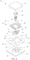
- FIG. 2 is an exploded diagram of the keyswitch in FIG. 1 .
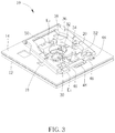
- FIG. 3 is a diagram of the keyswitch in FIG. 1 omitting a cap, a first elastic member and a first support member.
- FIG. 4 is a cross-sectional diagram of the keyswitch in FIG. 1 along a cross-sectional line A-A when a protruding rib presses a flexible rod to deform with downward rotation of the first support member.
- FIG. 5 is a cross-sectional diagram of the flexible rod in FIG. 4 crossing the protruding rib to be released.
- FIG. 6 is a cross-sectional diagram of the keyswitch in FIG. 1 along a cross-sectional line B-B.
- FIG. 7 is a cross-sectional diagram of the keyswitch in FIG. 6 when the cap is pressed.
- FIG. 8 is a cross-sectional diagram of the keyswitch in FIG. 1 along a cross-sectional line C-C.
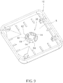
- FIG. 9 is an enlarged diagram of the cap in FIG. 1 from another viewing angle.
- FIG. 10 is a cross-sectional diagram of a keyswitch when a protruding rib pressing the flexible rod to deform with downward rotation of the first support member according to another embodiment of the present invention.
- FIG. 11 is a cross-sectional diagram of the keyswitch in FIG. 10 when the flexible rod crosses the protruding rib to be released.
- FIG. 1 is a diagram of a keyswitch 10 according to an embodiment of the present invention.
- FIG. 2 is an exploded diagram of the keyswitch 10 in FIG. 1 .
- the cap 16 is briefly depicted by dotted lines in FIG. 1 . As show in FIG. 1 and FIG.
- the keyswitch 10 includes a circuit board 12 , a bottom board 14 , a cap 16 , a base 18 , a cover 20 , a first elastic member 22 (preferably a spring, but not limited thereto), a second elastic member 24 (preferably a torsional spring, but not limited thereto), a support device 26 , a light receiver 28 , and a light emitter 30 .
- the circuit board 12 abuts against the bottom board 14 .
- the cap 16 is located above the bottom board 14 .
- the base 18 is disposed on the circuit board 12
- the cover 20 is disposed on the base 18 .
- the first elastic member 22 is disposed through the base 18 and the cover 20 for driving the cap 16 away from the base 18 to generate the automatic returning effect.
- the second elastic member 24 is fixed to the base 18 and has a flexible rod 32 .
- the support device 26 is disposed between the bottom board 14 and the cap 16 and includes a first support member 34 and a second support member 36 .
- the first support member 34 and the second support member 36 are movably connected to the cap 16 and the bottom board 14 and pivotably intersect with each other to make the cap 16 movable relative to the bottom board 14 .
- the first support member 34 has a sheet structure 38 .
- the sheet structure 38 has a protruding rib 40 and a shielding board 42 extending toward the circuit board 12 .
- FIG. 3 is a diagram of the keyswitch 10 in FIG. 1 omitting the cap 16 , the first elastic member 22 and the first support member 34 .
- the bottom board 14 has a hollow region 44 corresponding to the support device 26 .
- the first support member 34 is slidably connected to the cap 16 and is pivoted to the bottom board 14
- the second support member 36 is slidably connected to the bottom board 14 and is pivoted to the cap 16 .
- At least one limiting block 46 extends inwardly and horizontally from a first internal edge E 1 of the hollow region 44 corresponding to the end of the second support member 36 connected to the bottom board 14 .
- a first abutting board 48 extends horizontally from the base 18 toward the first internal edge E 1 of the hollow region 44
- a second abutting board 50 extends horizontally from the base 18 toward a second internal edge E 2 of the hollow region 44 corresponding to an end of the first support member 34 pivoted to the bottom board 14 . Accordingly, the first abutting board 48 and the second abutting board 50 can abut against the first internal edge E 1 and the second internal edge E 2 respectively to fix the base 18 in the hollow region 44 steadily.
- FIG. 4 is a cross-sectional diagram of the keyswitch 10 in FIG. 1 along a cross-sectional line A-A when the protruding rib 40 presses the flexible rod 32 to deform with downward rotation of the first support member 34 .
- FIG. 5 is a cross-sectional diagram of the flexible rod 32 in FIG. 4 crossing the protruding rib 40 to be released.
- the flexible rod 32 deforms downward with the protruding rib 40 (as shown in FIG. 4 ) when the first support member 34 rotates downward to make the protruding rib 40 press the flexible rod 32 and deformation of the flexible rod 32 caused by pressing of the protruding rib 40 is not enough to make the flexible rod 32 cross the protruding rib 40 .
- an upward recovering force generated by deformation of the flexible rod 32 increases to make the flexible rod 32 cross the protruding rib 40 , the deformed flexible rod 32 is no longer pressed by the protruding rib 40 .
- the flexible rod 32 is released to move upward to a position as shown in FIG.
- the keyswitch 10 can provide a clicky tactile feedback when the protruding rib 40 presses the flexible rod 32 to deform and then the flexible rod 32 is released, and the keyswitch 10 can further provide a tactile feedback with a click sound when the flexible rod 32 collides with the cover 20 .
- FIG. 6 is a cross-sectional diagram of the keyswitch 10 in FIG. 1 along a cross-sectional line B-B.
- FIG. 7 is a cross-sectional diagram of the keyswitch 10 in FIG. 6 when the cap 16 is pressed.
- the light receiver 28 is disposed on the circuit board 12
- the light emitter 30 is disposed on the circuit board 12 and is opposite to the light receiver 28 .
- the light receiver 28 could be preferably an infrared light receiving device and the light emitter 30 could be preferably an infrared light emitting device, but not limited thereto.
- the cap 16 when the cap 16 is not pressed, light emitted by the light emitter 30 can be incident to the light receiver 28 to establish light transmission between the light emitter 30 and the light receiver 28 .
- the cap 16 being pressed by an external force from a non-pressed position as shown in FIG. 6 to a pressed position as shown in FIG.
- the first support member 34 and the second support member 36 rotate with downward movement of the cap 16 , so as to move the shielding board 42 to block the light transmission between the light emitter 30 and the light receiver 28 .
- a triggering signal is generated and then transmitted to the circuit board 12 for performing a corresponding input function.
- the first elastic member 22 can drive the cap 16 from the presses position as shown in FIG. 7 upward to the non-pressed position as shown in FIG. 6 , so as to generate the effect that the cap 16 can return to its original position automatically.
- the shielding board 42 can return to a position above the light emitter 30 with upward movement of the first support member 34 (as shown in FIG. 6 ).
- the keyswitch 10 does not generate a triggering signal.
- the related description for the aforesaid optical triggering design it is commonly seen in the prior art and omitted herein.
- a cover structure 52 is formed on the base 18 corresponding to the light receiver 28 .
- the cover structure 52 covers the light receiver 28 and has an opening 54 to ensure that light emitted by the light emitter 30 can only pass through the opening 54 to be incident to the light receiver 28 .
- the present invention can solve the triggering failure problem caused by light emitted by the light emitter 30 being easily reflected to the light receiver 28 by the internal components (e.g. the cap 16 or the support device 26 ) of the keyswitch 10 .
- the present invention can efficiently solve the prior art problem that there exists an inconsistent time difference between keyswitch triggering and tactile feedback because the optical member and the protruding rib are disposed at the different positions. That is, via the design in which the tactile feedback effect and the light triggering effect can be generated by the sheet structure of the first support member, the keyswitch of the present invention can provide a consistent time difference between keyswitch triggering and tactile feedback when the user presses the cap.
- FIG. 8 is a cross-sectional diagram of the keyswitch 10 in FIG. 1 along a cross-sectional line C-C.
- FIG. 9 is an enlarged diagram of the cap 16 in FIG. 1 from another viewing angle.
- a scattering block 56 protrudes from a bottom surface S of the cap 16 toward the first elastic member 22 .
- the first elastic member 22 jackets the scattering block 56 to complete the assembly process of the cap 16 and the first elastic member 22 .
- the keyswitch 10 further includes a light emitting unit 58 .
- the light emitting unit 58 could be preferably a light emitting diode (but not limited thereto) and could be disposed on the circuit board 12 corresponding to the first elastic member 22 . Accordingly, light emitted by the light emitting unit 58 can pass through the first elastic member 22 , be incident into the scattering block 56 , and then be emitted out of the cap 16 via scattering of the scattering block 56 (as shown in FIG. 8 ). As such, the present invention can solve the problem that light may be blocked by the first elastic member 22 to project shadow on the cap 16 .
- the scattering block 56 could have an outer ring pad portion 60 and an inner ring connection portion 62 .
- the present invention can efficiently solve the aforesaid shadow problem.
- the scattering block 56 could include a plurality of arc-shaped blocks 64 arranged alternately, so as to efficiently prevent the shrink marks formed on the cap 16 corresponding to the scattering block 56 (i.e. the position having an uneven thickness).
- the scattering block 56 could preferably be formed on a center position of the bottom surface S of the cap 16 .
- the present invention could adopt the design that the scattering block is formed on the bottom surface of the cap for scattering light emitted by the light emitting unit without the aforesaid keyswitch feedback and optical triggering designs.
- FIG. 10 is a cross-sectional diagram of a keyswitch 100 when a protruding rib 114 pressing the flexible rod 32 to deform with downward rotation of the first support member 34 according to another embodiment of the present invention.
- FIG. 11 is a cross-sectional diagram of the keyswitch 100 in FIG. 10 when the flexible rod 32 crosses the protruding rib 114 to be released.
- Components both mentioned in this embodiment and the aforesaid embodiment represent components with similar structures or functions, and the related description is omitted herein. As shown in FIG. 10 and FIG.
- the keyswitch 100 includes the circuit board 12 , the bottom board 14 , the cap 16 , a base 102 , a cover 104 , the first elastic member 22 , the second elastic member 24 (only a portion of the second elastic member 24 corresponding to the flexible rod 32 is shown in FIGS. 10 and 11 ), the support device 26 , the light receiver 28 and the light emitter 30 (not shown in FIGS. 10 and 11 ).
- a first guiding surface structure 106 and a second guiding surface structure 108 are formed on the cover 104 and the base 102 respectively corresponding to the flexible rod 32 .
- the first guiding surface structure 106 and the second guiding surface structure 108 are separate from each other to cooperatively form a limiting rail 110 .
- the flexible rod 32 is movably inserted into the limiting rail 110 .
- the first support member 34 has a sheet structure 112 .
- the sheet structure 112 has the protruding rib 114 and the shielding board 42 extending toward the circuit board 12 .
- the flexible rod 32 abuts against the protruding rod 114 and moves long the limiting rail 110 from a position as shown in FIG. 10 to a position as shown in FIG. 11 . That is, the flexible rod 32 can cross the protruding rib 11 along the limiting rail 110 to provide a clicky tactile feedback when the user presses the cap 16 .
- the keyswitch 100 e.g. the base structural design and the light emitting design
- the present invention could adopt the design that the elastic member is omitted.
- the keyswitch could include the circuit board, the bottom board, the cap, the base, the cover, the elastic member (preferably a spring, but not limited thereto), the support device, the light receiver, and the light emitter.
- the elastic member is disposed through the base and the cover.
- the elastic member drives the cap away from the cap to generate the automatic returning effect.
- the bottom board has a hollow region corresponding to the support device.
- the first support member and the second support member are movably connected to the cap and the bottom board and pivotably intersect with each other.
- At least one limiting block extends inwardly and horizontally from a first internal edge of the hollow region corresponding to an end of the second support member connected to the bottom board.
- the limiting block can block the second support member to prevent the second support member from sliding laterally relative to the bottom board during rotation of the first support member and the second support member, so as to improve the pressing steadiness of the cap.
- the keyswitch can provide a non-clicky tactile feedback without a click sound when the user presses the cap.
- the aforesaid keyswitch e.g. the base structural design and the light emitting design
Landscapes
- Push-Button Switches (AREA)
- Input From Keyboards Or The Like (AREA)
Abstract
Description
Claims (22)
Applications Claiming Priority (2)
| Application Number | Priority Date | Filing Date | Title |
|---|---|---|---|
| TW108103026A TWI699795B (en) | 2019-01-28 | 2019-01-28 | Keyswitch |
| TW108103026 | 2019-01-28 |
Publications (2)
| Publication Number | Publication Date |
|---|---|
| US20200244261A1 US20200244261A1 (en) | 2020-07-30 |
| US11223357B2 true US11223357B2 (en) | 2022-01-11 |
Family
ID=71732798
Family Applications (1)
| Application Number | Title | Priority Date | Filing Date |
|---|---|---|---|
| US16/746,997 Active 2040-06-11 US11223357B2 (en) | 2019-01-28 | 2020-01-20 | Keyswitch |
Country Status (2)
| Country | Link |
|---|---|
| US (1) | US11223357B2 (en) |
| TW (1) | TWI699795B (en) |
Cited By (3)
| Publication number | Priority date | Publication date | Assignee | Title |
|---|---|---|---|---|
| US20220328266A1 (en) * | 2021-04-07 | 2022-10-13 | Darfon Electronics Corp. | Keyswitch assembly |
| US11721500B2 (en) | 2021-04-07 | 2023-08-08 | Darfon Electronics Corp. | Keyswitch assembly and support mechanism thereof |
| US11770123B2 (en) | 2018-01-05 | 2023-09-26 | Darfon Electronics Corp. | Optical keyswitch comprising a keycap having a light transmission area and a keycap projection area projected on a circuit board |
Citations (12)
| Publication number | Priority date | Publication date | Assignee | Title |
|---|---|---|---|---|
| US4418252A (en) | 1982-04-05 | 1983-11-29 | Daigle Phillip R | Key switch assembly |
| US6483050B1 (en) | 1999-11-11 | 2002-11-19 | Alps Electric Co., Ltd. | Key switch with easily attachable key top |
| TW200523964A (en) | 2004-01-15 | 2005-07-16 | Sunrex Technology Corp | Keyboard with detachable positioning plate |
| US20080211696A1 (en) | 2005-05-16 | 2008-09-04 | Research In Motion Limited | Key system for an electronic device |
| US20090277763A1 (en) | 2007-02-28 | 2009-11-12 | Research In Motion Limited | Backlighted key for a keypad of an electronic device |
| CN104299818A (en) | 2014-10-27 | 2015-01-21 | 东莞市名键电子科技有限公司 | Keyboard key |
| CN205943875U (en) | 2016-08-15 | 2017-02-08 | 张盛 | Can dismantlement type photoelectricity keyboard button switch structure |
| US20170169967A1 (en) * | 2015-12-14 | 2017-06-15 | Primax Electronics Ltd. | Optical switch keyboard |
| CN107359071A (en) | 2017-09-04 | 2017-11-17 | 东莞市高特电子有限公司 | A dust-proof thin mechanical keyboard switch and keyboard |
| CN108305806A (en) | 2018-02-14 | 2018-07-20 | 苏州达方电子有限公司 | Button and its key switch |
| TW201835959A (en) | 2017-03-15 | 2018-10-01 | 日商歐姆龍股份有限公司 | Key switch device |
| CN108962654A (en) | 2018-01-05 | 2018-12-07 | 达方电子股份有限公司 | Optical switch key |
-
2019
- 2019-01-28 TW TW108103026A patent/TWI699795B/en active
-
2020
- 2020-01-20 US US16/746,997 patent/US11223357B2/en active Active
Patent Citations (12)
| Publication number | Priority date | Publication date | Assignee | Title |
|---|---|---|---|---|
| US4418252A (en) | 1982-04-05 | 1983-11-29 | Daigle Phillip R | Key switch assembly |
| US6483050B1 (en) | 1999-11-11 | 2002-11-19 | Alps Electric Co., Ltd. | Key switch with easily attachable key top |
| TW200523964A (en) | 2004-01-15 | 2005-07-16 | Sunrex Technology Corp | Keyboard with detachable positioning plate |
| US20080211696A1 (en) | 2005-05-16 | 2008-09-04 | Research In Motion Limited | Key system for an electronic device |
| US20090277763A1 (en) | 2007-02-28 | 2009-11-12 | Research In Motion Limited | Backlighted key for a keypad of an electronic device |
| CN104299818A (en) | 2014-10-27 | 2015-01-21 | 东莞市名键电子科技有限公司 | Keyboard key |
| US20170169967A1 (en) * | 2015-12-14 | 2017-06-15 | Primax Electronics Ltd. | Optical switch keyboard |
| CN205943875U (en) | 2016-08-15 | 2017-02-08 | 张盛 | Can dismantlement type photoelectricity keyboard button switch structure |
| TW201835959A (en) | 2017-03-15 | 2018-10-01 | 日商歐姆龍股份有限公司 | Key switch device |
| CN107359071A (en) | 2017-09-04 | 2017-11-17 | 东莞市高特电子有限公司 | A dust-proof thin mechanical keyboard switch and keyboard |
| CN108962654A (en) | 2018-01-05 | 2018-12-07 | 达方电子股份有限公司 | Optical switch key |
| CN108305806A (en) | 2018-02-14 | 2018-07-20 | 苏州达方电子有限公司 | Button and its key switch |
Cited By (6)
| Publication number | Priority date | Publication date | Assignee | Title |
|---|---|---|---|---|
| US11770123B2 (en) | 2018-01-05 | 2023-09-26 | Darfon Electronics Corp. | Optical keyswitch comprising a keycap having a light transmission area and a keycap projection area projected on a circuit board |
| US11855624B2 (en) | 2018-01-05 | 2023-12-26 | Darfon Electronics Corp. | Optical switch comprising a movable member to rotate in response to movement of a support mechanism to change the intensity of received optical signal |
| US12160235B2 (en) | 2018-01-05 | 2024-12-03 | Darfon Electronics Corp. | Optical keyswitch with sliding end |
| US20220328266A1 (en) * | 2021-04-07 | 2022-10-13 | Darfon Electronics Corp. | Keyswitch assembly |
| US11721500B2 (en) | 2021-04-07 | 2023-08-08 | Darfon Electronics Corp. | Keyswitch assembly and support mechanism thereof |
| US11735379B2 (en) * | 2021-04-07 | 2023-08-22 | Darfon Electronics Corp. | Keyswitch assembly |
Also Published As
| Publication number | Publication date |
|---|---|
| TW202029244A (en) | 2020-08-01 |
| TWI699795B (en) | 2020-07-21 |
| US20200244261A1 (en) | 2020-07-30 |
Similar Documents
| Publication | Publication Date | Title |
|---|---|---|
| US10431402B2 (en) | Button switch with adjustable tactile feedback | |
| TWI711063B (en) | Optical keyswitch | |
| US9941068B2 (en) | Key structure | |
| US11223357B2 (en) | Keyswitch | |
| US9184001B2 (en) | Keycap, key structure and keyboard | |
| US10637470B2 (en) | Optical keyswitch | |
| TW201727685A (en) | Key structure | |
| US20170277227A1 (en) | Keyboard and notebook computer with same | |
| CN110211833A (en) | Press-key structure | |
| TWI669738B (en) | keyboard | |
| US11264185B2 (en) | Button switch and restoration assembly thereof | |
| US11551889B2 (en) | Key switch | |
| CN107305817A (en) | Key structure | |
| CN109088629B (en) | Push-button switch | |
| TW201828317A (en) | Key structure | |
| CN108807057B (en) | Key with pressing section falling sense | |
| US11551890B2 (en) | Keyswitch preventing lateral sliding | |
| US9141203B2 (en) | Key free mouse device | |
| JP4720435B2 (en) | Key switch | |
| CN109390177B (en) | Thin keys with a pressing paragraph feel | |
| CN109904022B (en) | button | |
| JP7694188B2 (en) | Switch device and key input device | |
| US10535477B2 (en) | Button switch and keyswitch thereof | |
| CN111081489B (en) | Key, keyboard and electronic device | |
| CN108346536A (en) | Key structure |
Legal Events
| Date | Code | Title | Description |
|---|---|---|---|
| AS | Assignment |
Owner name: DARFON ELECTRONICS CORP., TAIWAN Free format text: ASSIGNMENT OF ASSIGNORS INTEREST;ASSIGNORS:HSIEH, YU-CHUN;YANG, CHEN;LIU, CHIA-HUNG;SIGNING DATES FROM 20200116 TO 20200117;REEL/FRAME:051552/0553 |
|
| FEPP | Fee payment procedure |
Free format text: ENTITY STATUS SET TO UNDISCOUNTED (ORIGINAL EVENT CODE: BIG.); ENTITY STATUS OF PATENT OWNER: LARGE ENTITY |
|
| STPP | Information on status: patent application and granting procedure in general |
Free format text: DOCKETED NEW CASE - READY FOR EXAMINATION |
|
| STPP | Information on status: patent application and granting procedure in general |
Free format text: NON FINAL ACTION MAILED |
|
| STPP | Information on status: patent application and granting procedure in general |
Free format text: RESPONSE TO NON-FINAL OFFICE ACTION ENTERED AND FORWARDED TO EXAMINER |
|
| STPP | Information on status: patent application and granting procedure in general |
Free format text: NOTICE OF ALLOWANCE MAILED -- APPLICATION RECEIVED IN OFFICE OF PUBLICATIONS |
|
| STPP | Information on status: patent application and granting procedure in general |
Free format text: PUBLICATIONS -- ISSUE FEE PAYMENT VERIFIED |
|
| STCF | Information on status: patent grant |
Free format text: PATENTED CASE |
|
| MAFP | Maintenance fee payment |
Free format text: PAYMENT OF MAINTENANCE FEE, 4TH YEAR, LARGE ENTITY (ORIGINAL EVENT CODE: M1551); ENTITY STATUS OF PATENT OWNER: LARGE ENTITY Year of fee payment: 4 |