US11222734B2 - Burst-mode chirped pulse amplification method - Google Patents
Burst-mode chirped pulse amplification method Download PDFInfo
- Publication number
- US11222734B2 US11222734B2 US16/510,082 US201916510082A US11222734B2 US 11222734 B2 US11222734 B2 US 11222734B2 US 201916510082 A US201916510082 A US 201916510082A US 11222734 B2 US11222734 B2 US 11222734B2
- Authority
- US
- United States
- Prior art keywords
- pulse
- duration
- stretched
- pulses
- series
- Prior art date
- Legal status (The legal status is an assumption and is not a legal conclusion. Google has not performed a legal analysis and makes no representation as to the accuracy of the status listed.)
- Active, expires
Links
Images


Classifications
-
- H—ELECTRICITY
- H05—ELECTRIC TECHNIQUES NOT OTHERWISE PROVIDED FOR
- H05G—X-RAY TECHNIQUE
- H05G2/00—Apparatus or processes specially adapted for producing X-rays, not involving X-ray tubes, e.g. involving generation of a plasma
-
- G—PHYSICS
- G21—NUCLEAR PHYSICS; NUCLEAR ENGINEERING
- G21K—TECHNIQUES FOR HANDLING PARTICLES OR IONISING RADIATION NOT OTHERWISE PROVIDED FOR; IRRADIATION DEVICES; GAMMA RAY OR X-RAY MICROSCOPES
- G21K5/00—Irradiation devices
- G21K5/02—Irradiation devices having no beam-forming means
-
- H—ELECTRICITY
- H01—ELECTRIC ELEMENTS
- H01S—DEVICES USING THE PROCESS OF LIGHT AMPLIFICATION BY STIMULATED EMISSION OF RADIATION [LASER] TO AMPLIFY OR GENERATE LIGHT; DEVICES USING STIMULATED EMISSION OF ELECTROMAGNETIC RADIATION IN WAVE RANGES OTHER THAN OPTICAL
- H01S3/00—Lasers, i.e. devices using stimulated emission of electromagnetic radiation in the infrared, visible or ultraviolet wave range
- H01S3/005—Optical devices external to the laser cavity, specially adapted for lasers, e.g. for homogenisation of the beam or for manipulating laser pulses, e.g. pulse shaping
- H01S3/0057—Temporal shaping, e.g. pulse compression, frequency chirping
-
- H—ELECTRICITY
- H01—ELECTRIC ELEMENTS
- H01S—DEVICES USING THE PROCESS OF LIGHT AMPLIFICATION BY STIMULATED EMISSION OF RADIATION [LASER] TO AMPLIFY OR GENERATE LIGHT; DEVICES USING STIMULATED EMISSION OF ELECTROMAGNETIC RADIATION IN WAVE RANGES OTHER THAN OPTICAL
- H01S3/00—Lasers, i.e. devices using stimulated emission of electromagnetic radiation in the infrared, visible or ultraviolet wave range
- H01S3/05—Construction or shape of optical resonators; Accommodation of active medium therein; Shape of active medium
- H01S3/06—Construction or shape of active medium
- H01S3/063—Waveguide lasers, i.e. whereby the dimensions of the waveguide are of the order of the light wavelength
- H01S3/067—Fibre lasers
- H01S3/06754—Fibre amplifiers
- H01S3/06758—Tandem amplifiers
-
- H—ELECTRICITY
- H01—ELECTRIC ELEMENTS
- H01S—DEVICES USING THE PROCESS OF LIGHT AMPLIFICATION BY STIMULATED EMISSION OF RADIATION [LASER] TO AMPLIFY OR GENERATE LIGHT; DEVICES USING STIMULATED EMISSION OF ELECTROMAGNETIC RADIATION IN WAVE RANGES OTHER THAN OPTICAL
- H01S3/00—Lasers, i.e. devices using stimulated emission of electromagnetic radiation in the infrared, visible or ultraviolet wave range
- H01S3/10—Controlling the intensity, frequency, phase, polarisation or direction of the emitted radiation, e.g. switching, gating, modulating or demodulating
- H01S3/10007—Controlling the intensity, frequency, phase, polarisation or direction of the emitted radiation, e.g. switching, gating, modulating or demodulating in optical amplifiers
- H01S3/10023—Controlling the intensity, frequency, phase, polarisation or direction of the emitted radiation, e.g. switching, gating, modulating or demodulating in optical amplifiers by functional association of additional optical elements, e.g. filters, gratings, reflectors
-
- H—ELECTRICITY
- H01—ELECTRIC ELEMENTS
- H01S—DEVICES USING THE PROCESS OF LIGHT AMPLIFICATION BY STIMULATED EMISSION OF RADIATION [LASER] TO AMPLIFY OR GENERATE LIGHT; DEVICES USING STIMULATED EMISSION OF ELECTROMAGNETIC RADIATION IN WAVE RANGES OTHER THAN OPTICAL
- H01S3/00—Lasers, i.e. devices using stimulated emission of electromagnetic radiation in the infrared, visible or ultraviolet wave range
- H01S3/10—Controlling the intensity, frequency, phase, polarisation or direction of the emitted radiation, e.g. switching, gating, modulating or demodulating
- H01S3/13—Stabilisation of laser output parameters, e.g. frequency or amplitude
- H01S3/1301—Stabilisation of laser output parameters, e.g. frequency or amplitude in optical amplifiers
-
- H—ELECTRICITY
- H01—ELECTRIC ELEMENTS
- H01S—DEVICES USING THE PROCESS OF LIGHT AMPLIFICATION BY STIMULATED EMISSION OF RADIATION [LASER] TO AMPLIFY OR GENERATE LIGHT; DEVICES USING STIMULATED EMISSION OF ELECTROMAGNETIC RADIATION IN WAVE RANGES OTHER THAN OPTICAL
- H01S3/00—Lasers, i.e. devices using stimulated emission of electromagnetic radiation in the infrared, visible or ultraviolet wave range
- H01S3/23—Arrangements of two or more lasers not provided for in groups H01S3/02 - H01S3/22, e.g. tandem arrangements of separate active media
- H01S3/2308—Amplifier arrangements, e.g. MOPA
- H01S3/2316—Cascaded amplifiers
-
- H—ELECTRICITY
- H01—ELECTRIC ELEMENTS
- H01S—DEVICES USING THE PROCESS OF LIGHT AMPLIFICATION BY STIMULATED EMISSION OF RADIATION [LASER] TO AMPLIFY OR GENERATE LIGHT; DEVICES USING STIMULATED EMISSION OF ELECTROMAGNETIC RADIATION IN WAVE RANGES OTHER THAN OPTICAL
- H01S5/00—Semiconductor lasers
- H01S5/005—Optical components external to the laser cavity, specially adapted therefor, e.g. for homogenisation or merging of the beams or for manipulating laser pulses, e.g. pulse shaping
- H01S5/0057—Optical components external to the laser cavity, specially adapted therefor, e.g. for homogenisation or merging of the beams or for manipulating laser pulses, e.g. pulse shaping for temporal shaping, e.g. pulse compression, frequency chirping
-
- H—ELECTRICITY
- H01—ELECTRIC ELEMENTS
- H01S—DEVICES USING THE PROCESS OF LIGHT AMPLIFICATION BY STIMULATED EMISSION OF RADIATION [LASER] TO AMPLIFY OR GENERATE LIGHT; DEVICES USING STIMULATED EMISSION OF ELECTROMAGNETIC RADIATION IN WAVE RANGES OTHER THAN OPTICAL
- H01S5/00—Semiconductor lasers
- H01S5/50—Amplifier structures not provided for in groups H01S5/02 - H01S5/30
- H01S5/5009—Amplifier structures not provided for in groups H01S5/02 - H01S5/30 the arrangement being polarisation-insensitive
- H01S5/5018—Amplifier structures not provided for in groups H01S5/02 - H01S5/30 the arrangement being polarisation-insensitive using two or more amplifiers or multiple passes through the same amplifier
-
- H—ELECTRICITY
- H01—ELECTRIC ELEMENTS
- H01S—DEVICES USING THE PROCESS OF LIGHT AMPLIFICATION BY STIMULATED EMISSION OF RADIATION [LASER] TO AMPLIFY OR GENERATE LIGHT; DEVICES USING STIMULATED EMISSION OF ELECTROMAGNETIC RADIATION IN WAVE RANGES OTHER THAN OPTICAL
- H01S5/00—Semiconductor lasers
- H01S5/50—Amplifier structures not provided for in groups H01S5/02 - H01S5/30
- H01S5/5027—Concatenated amplifiers, i.e. amplifiers in series or cascaded
-
- H—ELECTRICITY
- H05—ELECTRIC TECHNIQUES NOT OTHERWISE PROVIDED FOR
- H05H—PLASMA TECHNIQUE; PRODUCTION OF ACCELERATED ELECTRICALLY-CHARGED PARTICLES OR OF NEUTRONS; PRODUCTION OR ACCELERATION OF NEUTRAL MOLECULAR OR ATOMIC BEAMS
- H05H15/00—Methods or devices for acceleration of charged particles not otherwise provided for, e.g. wakefield accelerators
-
- H—ELECTRICITY
- H01—ELECTRIC ELEMENTS
- H01J—ELECTRIC DISCHARGE TUBES OR DISCHARGE LAMPS
- H01J35/00—X-ray tubes
- H01J35/02—Details
- H01J35/04—Electrodes ; Mutual position thereof; Constructional adaptations therefor
- H01J35/06—Cathodes
- H01J35/065—Field emission, photo emission or secondary emission cathodes
-
- H—ELECTRICITY
- H05—ELECTRIC TECHNIQUES NOT OTHERWISE PROVIDED FOR
- H05H—PLASMA TECHNIQUE; PRODUCTION OF ACCELERATED ELECTRICALLY-CHARGED PARTICLES OR OF NEUTRONS; PRODUCTION OR ACCELERATION OF NEUTRAL MOLECULAR OR ATOMIC BEAMS
- H05H6/00—Targets for producing nuclear reactions
Definitions
- the present technology relates to chirped pulse amplification systems, and more specifically, relates to technology for increasing the MeV hot electron yield produced by short-pulse laser-target interactions over that produced by high-energy chirped pulse amplification systems.
- FIG. 1 illustrates the propagation of a pulse through a chirped pulse amplifier.
- a laser front end 10 produces a low energy short pulse “seed” 12 which, in this example, is a 10 nJ, 10 ps pulse.
- seed 12 is stretched in time by stretcher 14 to produce a 1.5 ns stretched pulse 16 .
- Amplifier 18 which may consist of one to several intermediate stages of amplification, amplifies pulse 16 to produce a 1 kJ, 1.5 ns high energy stretched pulse 20 .
- Compressor 22 compresses the pulse in time back to 10 ps.
- the output pulse from compressor 22 is a high energy compressed pulse 24 having an energy of up to 1 kJ and a pulse duration of 10 ps.
- the amplified short pulses are then typically directed and focused by suitable reflective optics sometime referred to as final optics such that they strike a target where they produce high energy (typically MeV) hot electrons.
- a short, intense (high power density, I, in e.g., W/cm 2 ) laser pulse passes through an amplifying medium, it begins to acquire additional phase from the non-linear index of refraction often denoted as the B-integral, with B ⁇ 2 ⁇ n 2 IL/ ⁇ , where n 2 is the non-linear index of refraction, L is the path length through the amplifying medium, and ⁇ is the laser wavelength).
- This process seeds instabilities in the beam resulting in distortion and ultimately, in a collapse into localized destructive filaments.
- CPA reduces these non-linear effects through as laser architectural method known as chirped pulse amplification.
- a short, low energy chirped pulse of length ⁇ 0 (the “seed pulse”) is first stretched in duration, using diffraction gratings or long lengths of dispersive material, to a longer pulse length ( ⁇ _stretch) which is typically nanoseconds length.
- the intensity of the stretched pulse, I_stretch is reduced by the ratio of ⁇ _stretch to ⁇ 0 so that it can be safely amplified without exceeding the B-integral limit of the amplifier.
- the stretched pulse is then passed through an amplifier medium amplifying it to higher energy. The longer wavelengths of the stretched pulse appear first in time, and the shorter wavelengths appear last.
- the amplified stretched pulse is passed through a pulse compressor comprised of diffraction gratings which are tuned so that the leading longer wavelengths of the pulse see a greater path length than the later shorter wavelengths such that they reach the final grating at nearly the same time where they are “recombined” to form an energetic pulse with the desired, much shorter pulse length ( ⁇ _compress).
- the energetic, compressed pulse can then be directed and focused onto a target by suitable reflective optics sometime referred to as final optics where it reaches an intensity high enough for ionization, plasma formation, and hot electron generation.
- the maximum energy of the compressed pulse is limited by two factors: B-integral in the amplifier 18 and damage to the final optics, the compressor 22 and/or focusing optic. These limits on energy are often far below (e.g., 10 times below) the available stored energy in the stretched pulse amplifier making CPA an inefficient process.
- the present technology is directed to a method for increasing the MeV hot electron yield produced by short-pulse (less than about 100 ps) laser-target interactions over that produced by conventional methods that utilize high-energy chirped puke amplification (CPA) systems.
- CPA high-energy chirped puke amplification
- These hot electrons can be subsequently used to create useful secondary or tertiary radiation, such as MeV x-rays, gamma-rays, protons, ions, neutrons and positrons, and electromagnetic radiation in the microwave to sub-mm region, produced through the interaction of such hot electrons with an appropriately high or low atomic number (Z) target (depending on the particular secondary source) which can be used, e.g., for the flash radiography dense objects using MeV x-rays.
- Z atomic number
- flash radiography is the radiography of objects which change in time done with a short burst (e.g. less than 100 ns) of x-rays source.
- CPA is considered to be the method of choice for amplifying short pulses to the high energy (kilojoule class) and peak power levels (10-TW to multi-PW) on a target needed for efficient production of a useful dose of hot electrons (and secondary radiation).
- CPA Burst-Mode CPA
- the maximum energy the final optics can handle without damage is increased by introducing that energy in a burst of short pulses, each separated from the other by a delay on the order of a nanosecond.
- the short pulses in the burst can be focused onto the target in such a manner that the sum of hot electrons produced by the burst is much greater than the number produced by the interaction of a single pulse with the target.
- This magnification of hot electron dose can be achieved by ensuring that each of the pulses strike the target at points separated by distances sufficient to avoid laser plasma interactions between the pulses. This method further provides a practical means to address this spacing need on target through small angle multiplexing of the pulses injected into the main amplifier.
- This method is sometimes referred to herein as Angularly Multiplexed Burst-mode CPA, or AMB-CPA. It further provides a practical means to reduce the laser plasma interaction between strike points on the target by using recessed targets or individual targets isolated by cones.
- the present technology can be implemented through front-end modifications to existing (or new) short pulse lasers such as National Ignition Facility-Advanced Radiographic Capability (NIF-ARC) laser at Lawrence Livermore National Laboratory (LLNL) or the short-pulse beam-lines on the Omega laser at the Laboratory for Laser Energetics (LLE).
- NIF-ARC National Ignition Facility-Advanced Radiographic Capability
- LNL Lawrence Livermore National Laboratory
- LLE Laser Energetics
- Recessed targets or targets with isolation cones as described above can be implemented on any high-Z target.
- Example uses of the present technology include, but are not limited to, short-pulse lasers, laser-driven flash x-ray radiography and laser-driven flash particle production.
- FIG. 1 illustrates the propagation of a pulse through a chirped pulse amplifier.
- FIG. 2A shows the output of a BM-CPA system.
- FIG. 2B shows the output of a conventional CPA system.
- FIG. 3 is a plot showing the damage threshold of pulse doublets as a function of delay and as a function of the pulse length of each of the constituent pulses and was compared to twice the damage threshold of the material at the corresponding pulse length.
- FIG. 4A shows a front view of the laser spots on the High-Z convertor material.
- FIG. 4B shows a side view of three laser pulses focused in respective isolation cones in the high-Z convertor material.
- FIG. 5A shows a burst of seven stretched pulses after amplification in the main amplification stage of a BM-CPA system.
- FIG. 5B shows a single pulse from the same amplifier of FIG. 6A but used in the traditional CPA approach.
- FIG. 6 illustrates an exemplary burst generator.
- FIGS. 7A-7D depict exemplary alternate configurations of the present technology.
- the present technology provides a method for extracting more energy from a CPA system, making it more efficient and reducing the size of the ultimate system required for a given need.
- the current invention is based on the discovery that the maximum energy the final optics can handle without damage is increased by introducing that energy in a burst of short pulses, each separated from the other by a delay on the order of a nanosecond.
- the energetic pulses in the burst are arranged such that they strike the target at locations far enough apart that laser-plasma interactions between them have a minimal impact on the efficiency of hot electron production.
- the duration of the hot electron burst will be equal in time to the duration of the laser pulse burst and can still be sufficiently prompt for flash radiography.
- FIG. 2A shows the output 30 of a BM-CPA system. A series of seven pulses is directed onto a hot electron target 32 .
- FIG. 2B shows the output 40 from a conventional CPA system. The output is directed and focused by suitable reflective optics sometime referred to as the final optics onto a hot electron target 42 .
- the amplifier and final optics, diffraction gratings and focusing optic are the same in both FIG. 2A and FIG. 2B . Pulses are drawn to comply with the B-integral and final optics damage limits of the same, typical CPA output stage.
- FIG. 3 is a plot showing the damage threshold of these pulse doublets as a function of delay and as a function of the pulse length of each of the constituent pulses and was compared to twice the damage threshold of the material at the corresponding pulse length.
- MLD multi-laver dielectric
- the damage threshold of the MLD reflector increased for delays greater than about 5 ps.
- the MLD reflector could withstand 80% of the double-single puke limit—in other words, from the point of view of laser damage, the MLD reflector responded to the second pulse nearly as if the first pulse did't arrived before it. From this result, it is determined that a burst of 10 ps pulses having delays greater than about 100 ps could be safely used in a compressor, each having 80% of the damage limit of a single 10 ps pulse.
- FIG. 4A shows a front view of the laser spots 51 - 57 on the High-Z convertor material. 60 . Note that the spots have a diameter of about 60 ⁇ m and are 160 ⁇ m apart on the High-Z convertor material 60 , which is 500 ⁇ m in diameter.
- FIG. 4B shows a side view of laser pulses 51 - 53 of FIG. 4A . Laser pulses 51 - 53 are focused in respective isolation cones 61 - 63 either in or on the high-Z convertor material 60 . Laser pulse 51 arrives at the target at time T 0 .
- Pulse 52 and 53 arrive at the target at T 0 plus 1 ns and T 0 plus 2 ns, respectively.
- Pulses 54 - 57 arrive at the target at T 0 plus 3 ns to T 0 plus 7 ns. respectively. Note that the ordering of these pulses described here is not necessarily the only optimal sequencing.
- the isolation cones may consist of a re-entrant hole in high-Z converter material, or they may be cones placed on the high-Z material.
- the cone in this second case may be formed in plastic and coated for high reflection with gold or another reflective material.
- An exemplary hydro-dynamic simulation of the plasma interaction along its radial axis revealed that the separation between pulse spots can be on the order of hundreds of microns when the compressed pulse length is 10 ps and the delay between pulses in the burst is a nanosecond.
- Another exemplary hydro-dynamic simulation showed a reduced laser plasma interaction radius produced when a pulse is focused into a re-entrant hole or an isolating cone.
- the separation between each pulse may be reduced further by focusing the beams into re-entrant holes or isolation cones.
- the “exclusion zone” between pulses could change as a function of the compressed pulse length, the delay between pulses, the construction of the isolation cones, and the compressed pulse energy.
- this spatial separation can be achieved through angular multiplexing of the beams.
- This embodiment of BM-CPA is sometimes referred to as Angularly Multiplexed Burst-mode CPA (AMB-CPA).
- AMB-CPA Angularly Multiplexed Burst-mode CPA
- each pulse in the beam is formatted with a slightly different angle ( ⁇ ) in the “front-end” of the laser prior to its injection into the amplification chain.
- the beams propagate with these different angles throughout the system, from the stretcher to the amplifier to the compressor and finally out the focusing optic. These angles are arranged such that when the pulses leave the focusing optic, they are focused into the correct pattern on the target.
- a desirable pulse strike delay pattern for a seven-pulse burst of these pulses on the target is shown in FIG. 4B .
- FIG. 5A shows a burst of seven stretched pulses after amplification in the main amplification stage but prior to compression of a BM-CPA system compared to a single pulse used in the same amplifier in the traditional CPA approach of FIG. 5B .
- the intensity of each stretched pulse in FIG. 5A is maintained below maximum allowable B-integral limit of the amplifier, and the angles are chosen to hit the target as shown in FIG. 4A .
- the 1.5 ns duration stretched pulses are separated by 1.5.ns.
- the energy of each pulse in FIG. 5A is 80% of the pulse in FIG. 5B so that upon compression, each pulse in the burst is below the damage threshold of the short pulse optics as described above.
- FIG. 6 An exemplary burst generator 80 is shown in FIG. 6 .
- this figure depicts an example of technology that will take an input pulse of light and produce an output series of pulses, such as, for example, shown in FIGS. 2A and 5A .
- the output of this device can be directed at different angles such that each pulse of the series of pulses propagates through the final amplifier of a CPA system at a slightly different angle from that of each other pulse of the series of pulses.
- FIG. 6 shows a hyper-Michelson interferometer layout that creates four equally-spaced pulses in time. Based on this disclosure, those skilled in the art will understand that this concept, as well as alternate configurations, can be used to produce a desired number of output pulses and a desired spacing in time of such pulses.
- a single input pulse 81 is directed onto beamsplitter (BS) 82 .
- the burst generator further includes BS 84 , BS 86 , mirrors 88 , 90 , 92 and 94 .
- the device includes neutral density (ND) filters 96 - 99 , a polarizer 95 and a Pockets Cell 100 .
- ND filters contributes to produce a series of output pulses 102 that are progressively increasing in intensity. This progressive increase in intensity may be useful in accessing more power from a subsequent amplifier, as well as preventing damage therein and in the compressor and subsequent optic.
- This device includes a beam diagnostic package 104 .
- each pulse of the series of output pulses can be directed at slightly different angles into a subsequent amplifier, such as the final amplifier of a CPA system. For example, a slight change in the angular orientation of the beamsplitters repoints the far field of each pulse of the series of pulses. Those skilled in the art will understand other ways to change the pointing of the output series of pulses.
- FIGS. 7A-7D depict exemplary alternate configurations of the present technology.
- the configurations place the burst generator 80 at alternate locations within a CPA system.
- the alternate configurations which consists of alternate burst generator positions within the CPA system, are listed as examples 1-4 as follows:
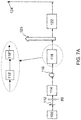
- Example 1 of FIG. 7A in general is a block diagram showing a single seed pulse, a burst generator, a stretcher, an amplifier (pre and final) and a compressor. All systems of examples 1-4 ( FIGS. 7A-7D ) are followed by focusing optics for directing the pulses onto the target (not shown) such as target 60 of FIGS. 4A and 4B .
- a laser front end 100 produces a low energy short pulse “seed” 112 .
- Seed pulse 112 passes through burst generator 80 to produce a series of short pulses which are stretched in time by stretcher 114 to produce a series of stretched pulses 116 .
- Amplifier 118 which may include a preamplifier 118 ′ and a final amplifier 118 ′′, amplifies the series of stretched pulses 116 to produce a series of stretched pulses 120 .
- Compressor 122 compresses series of amplified pulses 120 in time to produce a series of compressed pulses 124 .
- Example 2 of FIG. 7B in general is a block diagram showing a single seed pulse, a stretcher, a burst generator, an amplifier (pre and final) and a compressor.
- a laser front end 100 produces a low energy short pulse “seed” 112 .
- Seed 112 passes through pulse stretcher 114 to produce a stretched pulse 116 which then passes through burst generator 80 to produce a series of stretched pulses which are then directed through amplifier 118 .
- Amplifier 118 which may include a preamplifier 118 ′ and a final amplifier 118 ′′, amplifies pulses 116 to produce a series of amplified pulses 120 .
- Compressor 122 compresses the pulses in time.
- the output pulses from compressor 122 are a series of compressed pulses 124 .
- Example 3 of FIG. 7C in general is a block diagram showing a single seed pulse, a stretcher, a pre-amplifier, a burst generator, a final amplifier and a compressor.
- a laser front end 100 produces a low energy short pulse “seed” 112 .
- Seed 112 passes through pulse stretcher 114 to produce a stretched pulse 116 which, as shown in the insert, then passes through preamplifier 118 ′ and then burst generator 80 followed by final amplifier 118 ′ which amplifies the series of pre-amplified pulses 116 to produce a high energy stretched series of pulses 120 that are directed into compressor 122 which compresses the series of amplified pulses to produce a series of high energy output pulses 124 .
- Example 4 of FIG. 7D in general is a block diagram showing a single seed pulse, a stretcher, an amplifier (pre and final), a burst generator, and a compressor.
- a laser front end 100 produces a low energy short pulse “seed” 112 .
- Seed 112 passes through pulse stretcher 114 to produce a stretched pulse 116 which then passes amplifier 118 .
- Amplifier 118 which may include a preamplifier 118 ′ and a final amplifier 118 ′′, amplifies pulse 116 to produce a high energy stretched series of pulses 120 . that are directed into Burst generator 80 which produces a series of amplified pulses.
- Compressor 122 compresses the series of amplified pulses to produce a series of high energy output pulses 124 .
- the hot electron bursts of this technology can be used to create secondary particle bursts through the interaction of these hot electrons with a suitable target.
- high energy photons (x-rays) bursts can be produced by interacting the hot electron burst with a high-Z material.
- High energy x-rays are often used for flash radiography of dense objects. For sufficiently dense materials, MeV x-rays are desirable.
- BM-CPA or AMB-CPA can be used to create multiple images at different time by triggering different BM-CPA or AMB-CPA beamlines at the required image times to produce short pulse bursts; each pulse burst must be focused to a region of the target sufficiently far apart that target fratricide from earlier pulse bursts does not affect a pulse burst later in time. It is also clear that these images can be created along different radiographic axes by aiming the BM-CPA or AMB-CPA beams at targets located at different points of view with respect to the object being radiographed.
- a method for increasing the MeV hot electron yield and secondary radiation produced by short-pulse laser-target interactions with an appropriately high or low atomic number (Z) target can be used, e.g., for the flash radiography of dense objects.
- a burst-mode chirped pulse amplification method comprising:
- each amplified stretched-duration output pulse of said series of amplified stretched-duration pulses is delayed from its immediately preceding amplified stretched-duration output pulse by a delay time that is sufficiently long such that the total optical fluence of said series of amplified stretched-duration pulses that can pass through and not damage said pulse compressor is greater than the minimum optical fluence of a single pulse that would damage said pulse compressor.
- step of utilizing a burst generator comprises:
- each short-duration pulse of said series of short-duration pulses is delayed from its immediately preceding short-duration pulse by said delay time;
- step of utilizing a burst generator comprises:
- step of utilizing a burst generator comprises:
- step of utilizing a burst generator comprises:
- each amplified stretched-duration pulse of said series of amplified stretched-duration pulses is delayed from its immediately preceding amplified stretched-duration pulse by said delay time.
- each said stretched-duration pulse is directed at an angle, different from the angle at which all other said stretched-duration pulses of said series of stretched-duration pulses are directed, through said optical amplifier.
- each said stretched-duration pulse is directed at an angle, different from the angle at which all other said stretched-duration pulses of said series of stretched-duration pulses are directed, through said optical amplifier.
- each said stretched-duration pulse is directed at an angle, different from the angle at which all other said stretched-duration pulses of said series of stretched-duration pulses are directed, through said optical amplifier.
- said target comprises a material, or a combination of materials, having an appropriate atomic number to produce secondary or tertiary radiation selected from the group consisting of x-rays, gamma rays, protons, ions, neutrons, positrons and electromagnetic radiation in the microwave to sub-mm region.
- each said cone comprises plastic.
- a burst-mode chirped pulse amplifier comprising:
- a chirped pulse amplifier comprising a series of elements located on an optical axis, wherein said series of elements comprises a pulse stretcher, an optical amplifier and a pulse compressor;
- a burst generator operatively placed on said optical axis at a location selected from the group consisting of (i) before said pulse stretcher, between said pulse stretcher and said optical amplifier, between stages of said optical amplifier and between said optical amplifier and said pulse compressor.
Landscapes
- Physics & Mathematics (AREA)
- Electromagnetism (AREA)
- Optics & Photonics (AREA)
- Engineering & Computer Science (AREA)
- Plasma & Fusion (AREA)
- Condensed Matter Physics & Semiconductors (AREA)
- General Physics & Mathematics (AREA)
- General Engineering & Computer Science (AREA)
- High Energy & Nuclear Physics (AREA)
- Spectroscopy & Molecular Physics (AREA)
- Lasers (AREA)
Abstract
Description
- 1. M. D. Perry, et. al., Rev. Sci. Instrum. 70, 265 (1999)
- 2. R. D. Edwards, et, al., Appl. Phys. Lett. 80 (2002) 2129.
- 3. Y. Glinec, et al., Phys. Rev. Lett. 94 (2005) 025003.
- 4. C. Courtois, et. al., Phys. Plasmas 20 (2011) 023101.
- 5. C. Courtois, et, al., Phys. Plasmas 20 (2013) 083114.
Claims (25)
Priority Applications (1)
| Application Number | Priority Date | Filing Date | Title |
|---|---|---|---|
| US16/510,082 US11222734B2 (en) | 2018-07-13 | 2019-07-12 | Burst-mode chirped pulse amplification method |
Applications Claiming Priority (2)
| Application Number | Priority Date | Filing Date | Title |
|---|---|---|---|
| US201862697571P | 2018-07-13 | 2018-07-13 | |
| US16/510,082 US11222734B2 (en) | 2018-07-13 | 2019-07-12 | Burst-mode chirped pulse amplification method |
Publications (2)
| Publication Number | Publication Date |
|---|---|
| US20200020459A1 US20200020459A1 (en) | 2020-01-16 |
| US11222734B2 true US11222734B2 (en) | 2022-01-11 |
Family
ID=69139579
Family Applications (1)
| Application Number | Title | Priority Date | Filing Date |
|---|---|---|---|
| US16/510,082 Active 2040-03-24 US11222734B2 (en) | 2018-07-13 | 2019-07-12 | Burst-mode chirped pulse amplification method |
Country Status (3)
| Country | Link |
|---|---|
| US (1) | US11222734B2 (en) |
| EP (1) | EP3821270B1 (en) |
| WO (1) | WO2020014684A1 (en) |
Families Citing this family (1)
| Publication number | Priority date | Publication date | Assignee | Title |
|---|---|---|---|---|
| CN112271533B (en) * | 2020-11-18 | 2024-07-16 | 北京大学 | Chirped pulse amplification system and implementation method thereof |
Citations (8)
| Publication number | Priority date | Publication date | Assignee | Title |
|---|---|---|---|---|
| US20080013163A1 (en) | 2006-07-11 | 2008-01-17 | Mobius Photonics, Inc. | Light source with precisely controlled wavelength-converted average power |
| US20090246413A1 (en) * | 2008-03-27 | 2009-10-01 | Imra America, Inc. | Method for fabricating thin films |
| US20090246530A1 (en) * | 2008-03-27 | 2009-10-01 | Imra America, Inc. | Method For Fabricating Thin Films |
| US7787175B1 (en) * | 2006-01-20 | 2010-08-31 | Raydiance, Inc. | Pulse selecting in a chirped pulse amplification system |
| US20110182306A1 (en) | 2008-02-19 | 2011-07-28 | Bergmann Messgerate Entwicklung Kg | Generation of burst of laser pulses |
| US20140002927A1 (en) | 2012-06-28 | 2014-01-02 | Hitachi Global Storage Technologies Netherlands B.V. | Write head structure designed for temperature insensitive writing performance |
| US20160084892A1 (en) | 2014-09-22 | 2016-03-24 | Siemens Aktiengesellschaft | Method and a control unit for validating an electric power plant |
| US20170085053A1 (en) | 2012-10-16 | 2017-03-23 | Imra America, Inc. | Compact ultra-short pulse source amplifiers |
Family Cites Families (2)
| Publication number | Priority date | Publication date | Assignee | Title |
|---|---|---|---|---|
| US7486705B2 (en) * | 2004-03-31 | 2009-02-03 | Imra America, Inc. | Femtosecond laser processing system with process parameters, controls and feedback |
| FR2999023B1 (en) * | 2012-12-04 | 2016-10-21 | Amplitude Systemes | SYSTEM AND METHOD FOR GENERATING HIGH-POWER ULTRACOURSE LASER PULSE SALVATION |
-
2019
- 2019-07-12 US US16/510,082 patent/US11222734B2/en active Active
- 2019-07-12 EP EP19834245.3A patent/EP3821270B1/en active Active
- 2019-07-12 WO PCT/US2019/041721 patent/WO2020014684A1/en unknown
Patent Citations (8)
| Publication number | Priority date | Publication date | Assignee | Title |
|---|---|---|---|---|
| US7787175B1 (en) * | 2006-01-20 | 2010-08-31 | Raydiance, Inc. | Pulse selecting in a chirped pulse amplification system |
| US20080013163A1 (en) | 2006-07-11 | 2008-01-17 | Mobius Photonics, Inc. | Light source with precisely controlled wavelength-converted average power |
| US20110182306A1 (en) | 2008-02-19 | 2011-07-28 | Bergmann Messgerate Entwicklung Kg | Generation of burst of laser pulses |
| US20090246413A1 (en) * | 2008-03-27 | 2009-10-01 | Imra America, Inc. | Method for fabricating thin films |
| US20090246530A1 (en) * | 2008-03-27 | 2009-10-01 | Imra America, Inc. | Method For Fabricating Thin Films |
| US20140002927A1 (en) | 2012-06-28 | 2014-01-02 | Hitachi Global Storage Technologies Netherlands B.V. | Write head structure designed for temperature insensitive writing performance |
| US20170085053A1 (en) | 2012-10-16 | 2017-03-23 | Imra America, Inc. | Compact ultra-short pulse source amplifiers |
| US20160084892A1 (en) | 2014-09-22 | 2016-03-24 | Siemens Aktiengesellschaft | Method and a control unit for validating an electric power plant |
Non-Patent Citations (2)
| Title |
|---|
| Intematicna Search Report and Written Opinion for PCT/US2019/041721 corresponding to U.S. Appl. No. 16/510,082, 9 pages, dated Oct. 30, 2019. |
| International Preliminary Report on Patentability from PCT/US2019/041721, dated Jan. 19, 2021. |
Also Published As
| Publication number | Publication date |
|---|---|
| EP3821270A4 (en) | 2022-04-27 |
| EP3821270A1 (en) | 2021-05-19 |
| EP3821270B1 (en) | 2024-04-03 |
| WO2020014684A1 (en) | 2020-01-16 |
| US20200020459A1 (en) | 2020-01-16 |
Similar Documents
| Publication | Publication Date | Title |
|---|---|---|
| Obenschain et al. | High-energy krypton fluoride lasers for inertial fusion | |
| Hecht et al. | a History | |
| Tochitsky et al. | Laser-driven collisionless shock acceleration of ions from near-critical plasmas | |
| Pennington et al. | Petawatt laser system and experiments | |
| Badziak et al. | Experimental evidence of differences in properties of fast ion fluxes from short-pulse and long-pulse laser-plasma interactions | |
| US11222734B2 (en) | Burst-mode chirped pulse amplification method | |
| CA2800599C (en) | All-optical method and system for generating ultrashort charged particle beam | |
| Bellido et al. | Characterization of protons accelerated from a 3 TW table-top laser system | |
| Hecht | The history of the X-ray laser | |
| US6678351B1 (en) | Laser radiography forming bremsstrahlung radiation to image an object | |
| Kotaki et al. | Compact X-ray sources by intense laser interactions with beams and plasmas | |
| Roth et al. | Intense ion beams accelerated by petawatt-class lasers | |
| Allaria et al. | The FERMI seeded-FEL facility: Status and perspectives | |
| Nishiuchi et al. | Ion acceleration experiment with the high intensity, high contrast J-KAREN-P laser system | |
| Ivanov et al. | Tabletop Laser-Plasma Electron Accelerators: Experimental Designs, Acceleration Mechanisms and Some Applications | |
| Veisz et al. | Relativistic electron acceleration from nanotips | |
| Aktan | Laser pump-probe experimental studies in the relativistic regime | |
| Fourmaux et al. | Laser-based proton acceleration experiments at the ALLS facility using a 200 TW high intensity laser system | |
| Kuehl et al. | PHELIX–status and first experiments | |
| Singh et al. | Observation of quasi-monoenergetic electrons in the plasma produced by sub-nanosecond laser pulse | |
| Pomerantz et al. | Laser-ion acceleration from transparent overdense plasmas at the Texas Petawatt | |
| Steingruber et al. | Prepulse dependence of soft X-ray spectra from plasmas created by femtosecond IR laser pulses on solids | |
| Park et al. | Design study of the KAERI Compton X-ray source depending on the laser intensity in the linear or non-linear regime | |
| Belkov et al. | RFNC–VNIIEF Study Into Interaction Between Intense Laser Pulses and Matter | |
| Kaganovich et al. | Generation of high-energy electrons in a double gas jet and laser wakefield acceleration |
Legal Events
| Date | Code | Title | Description |
|---|---|---|---|
| FEPP | Fee payment procedure |
Free format text: ENTITY STATUS SET TO UNDISCOUNTED (ORIGINAL EVENT CODE: BIG.); ENTITY STATUS OF PATENT OWNER: LARGE ENTITY |
|
| AS | Assignment |
Owner name: U.S. DEPARTMENT OF ENERGY, DISTRICT OF COLUMBIA Free format text: CONFIRMATORY LICENSE;ASSIGNOR:LAWRENCE LIVERMORE NATIONAL SECURITY, LLC;REEL/FRAME:050199/0453 Effective date: 20190822 |
|
| STPP | Information on status: patent application and granting procedure in general |
Free format text: DOCKETED NEW CASE - READY FOR EXAMINATION |
|
| AS | Assignment |
Owner name: LAWRENCE LIVERMORE NATIONAL SECURITY, LLC, CALIFORNIA Free format text: ASSIGNMENT OF ASSIGNORS INTEREST;ASSIGNORS:AUFDERHEIDE, MAURICE B.;ALESSI, DAVID A.;BUDE, JEFFREY D.;AND OTHERS;SIGNING DATES FROM 20190711 TO 20190904;REEL/FRAME:050349/0232 Owner name: LAWRENCE LIVERMORE NATIONAL SECURITY, LLC, CALIFOR Free format text: ASSIGNMENT OF ASSIGNORS INTEREST;ASSIGNORS:AUFDERHEIDE, MAURICE B.;ALESSI, DAVID A.;BUDE, JEFFREY D.;AND OTHERS;SIGNING DATES FROM 20190711 TO 20190904;REEL/FRAME:050349/0232 |
|
| STPP | Information on status: patent application and granting procedure in general |
Free format text: NON FINAL ACTION MAILED |
|
| STPP | Information on status: patent application and granting procedure in general |
Free format text: NOTICE OF ALLOWANCE MAILED -- APPLICATION RECEIVED IN OFFICE OF PUBLICATIONS |
|
| STPP | Information on status: patent application and granting procedure in general |
Free format text: PUBLICATIONS -- ISSUE FEE PAYMENT RECEIVED |
|
| STPP | Information on status: patent application and granting procedure in general |
Free format text: PUBLICATIONS -- ISSUE FEE PAYMENT VERIFIED |
|
| STCF | Information on status: patent grant |
Free format text: PATENTED CASE |
|
| MAFP | Maintenance fee payment |
Free format text: PAYMENT OF MAINTENANCE FEE, 4TH YEAR, LARGE ENTITY (ORIGINAL EVENT CODE: M1551); ENTITY STATUS OF PATENT OWNER: LARGE ENTITY Year of fee payment: 4 |